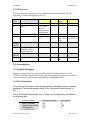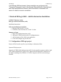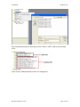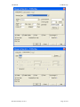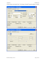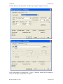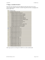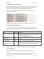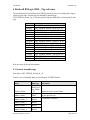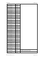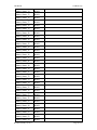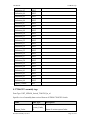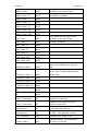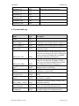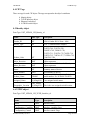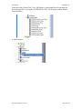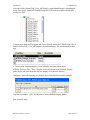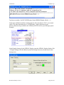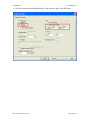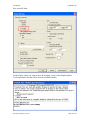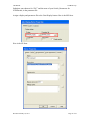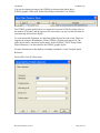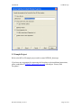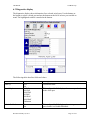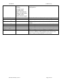
1
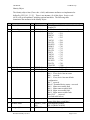
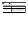
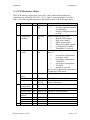
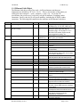
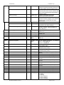
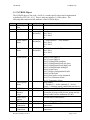
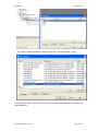
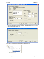
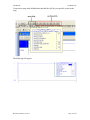
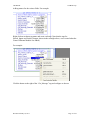
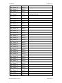
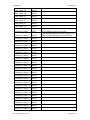
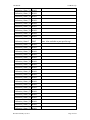
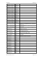
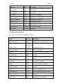
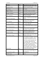
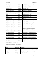
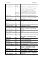
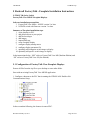
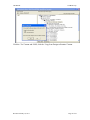
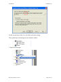
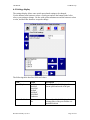
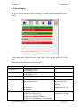
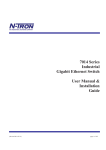
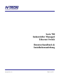
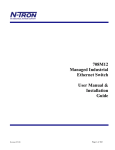
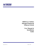
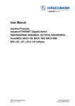
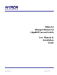
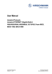
CIP User Manual & Installation Guide CIP Manual N-TRON Corp. N-TRON CIP Manual 1 Introduction ................................................................................................................................... 3 2 CIP Components .......................................................................................................................... 3 2.1 Electronic Data Sheet (EDS) ................................................................................................. 3 2.2 CIP Objects ........................................................................................................................... 3 2.2.1 TCP/IP Interface Object ................................................................................................. 6 2.2.2 Ethernet Link Object ...................................................................................................... 7 2.2.3 N-TRON Object.............................................................................................................. 9 2.3 CIP Services ........................................................................................................................ 11 2.4 Accessing Data ................................................................................................................... 11 2.4.1 Explicit Messaging ....................................................................................................... 11 2.4.2 I/O Connections ........................................................................................................... 11 3 Rockwell RSLogix 5000 – Add-On Instruction Installation ......................................................... 12 3.1 Configuration of RSLogix project ........................................................................................ 12 3.2 Input_Assembly Parameter ................................................................................................. 21 3.3 Switch_Parameters Parameter ........................................................................................... 22 3.4 Explicit Messaging Options ................................................................................................. 22 3.5 Troubleshooting................................................................................................................... 22 3.6 Sample Project .................................................................................................................... 23 4 Rockwell RSLogix 5000 – Tag reference ................................................................................... 24 4.1 Generic assembly tags ........................................................................................................ 24 4.2 7506GX2 assembly tags .................................................................................................... 33 4.3 System fault tags ................................................................................................................. 35 4.4 CIP Tags ............................................................................................................................. 36 4.5 Identity object ...................................................................................................................... 36 4.6 TCPIP object ....................................................................................................................... 36 4.7 Ethernet Link object ............................................................................................................ 37 4.8 N-TRON Switch object ........................................................................................................ 39 5 Rockwell FactoryTalk - Faceplate Installation Instructions ........................................................ 42 5.1 Configuration of FactoryTalk View Faceplate Displays....................................................... 42 5.2 Sample Project .................................................................................................................... 53 6 Rockwell FactoryTalk - Faceplate quick reference guide ........................................................... 54 6.1 Introduction.......................................................................................................................... 54 6.2 Home display....................................................................................................................... 55 6.3 Diagnostics display.............................................................................................................. 57 6.4 Settings display ................................................................................................................... 59 6.5 Alarm display ....................................................................................................................... 60 7 Support ....................................................................................................................................... 61 8 References ................................................................................................................................. 61 9 Revisions .................................................................................................................................... 61 Revision February 18, 2011 Page 2 of 61 CIP Manual N-TRON Corp. 1 Introduction EtherNet/IP™, better known as the Common Industrial Protocol (CIP™), was designed for use in process control and industrial automation applications. CIP was designed to provide consistent device access to eliminate the need for vendor specific software for configuration and monitoring of individual devices. N-TRON switches with CIP support can be used to communicate with other industrial devices, such as Rockwell controllers. 2 CIP Components The following CIP components are available with N-TRON CIP enabled switches. 2.1 Electronic Data Sheet (EDS) An electronic datasheet for each N-TRON switch is provided. In a Rockwell environment EDS files are installed using the “EDS Hardware Installation Tool”. This allows N-TRON switches to be recognized in an RSLinx environment. 2.2 CIP Objects “Objects” are used to organize various information about the switch. There are four types of objects provided. Three are specified by the ODVA, and one is N-TRON specific: Identity object TCP/IP Interface object Ethernet Link object N-TRON switch object Standard “services” are associated with objects. Services exist for reading an attribute, setting an attribute, resetting a device, etc. See references [1] and [2] for specific details. The following sections describe the attributes associated with each object type, such as attribute Id number and data format. All attributes can be read, but only some can be set, as shown by the “Set” column. Revision February 18, 2011 Page 3 of 61 CIP Manual N-TRON Corp. Identity Object The identity object class (Class code = 0x01) and instance attributes are implemented as defined by CIP Vol 1, 5-2 [1]. There is one instance (1) of this object. Service code (0x32) will get all attributes, including optional attributes. The following table summarizes the attributes in the Identity object. Id Name 1 Format Description Vendor ID UINT (16) 2 3 Device Type Product Code UINT (16) UINT (16) 4 5 Major Revision Minor Revision Status USINT (8) USINT (8) WORD (16) 6 Serial Number UDINT (32) 7 Product Name 15 Assigned_Name SHORT_STRI NG STRINGI 1006. This is N-TRON’s ODVA EtherNet/IP Vendor ID. 0x0C. Communications Adapter Switch product code: 708TX = 701 708FX2 = 703 716TX = 705 716FX2 = 706 7018TX = 708 7018FX2 = 709 708M12 = 710 711FX3 = 711 7010TX = 713 709FX = 714 710FX2 = 715 714FX6 = 717 712FX4 = 718 7012FX2 = 719 7026TX = 720 7506GX2 = 7506 Major version of CIP implementation. Minor version of CIP implementation. Summary status of device. Bits: Bit 0 If set, device has an owner Bit 1 reserved Bit 2 If set, device has non-default configuration Bit 3 reserved Bits 4-7 Extended device status – not used Bit 8 Minor recoverable fault Bit 9 Minor unrecoverable fault Bit 10 Major recoverable fault Bit 11 Major unrecoverable fault Bits 12-15 reserved (see fault table below) Serial number of the device. This is the last 4 octets of the base switch MAC. Switch Model Number. EX: N-TRON 7018FX2 This is the user assigned switch name. Revision February 18, 2011 Set Set Page 4 of 61 CIP Manual 17 Geographic_Location N-TRON Corp. Set STRINGI This is the user assigned switch location. The table below defines fault bits within the Status attribute of the Identity object. Bit Called Definition 8 Minor Recoverable Fault 9 10 Minor Unrecoverable Fault Major Recoverable Fault 11 Major Unrecoverable Fault Power supply 1, Power supply 2, N-Ring Full, System, Port utilization, Temperature, N-Link partner is down, N-Link integrity fault Configuration device error N-Ring partial low, N-Ring partial high, N-Ring multiple managers, Boot loader version, N-Link partner port unknown, N-Link multiple masters, N-Link control fault, N-Link configuration fault none Revision February 18, 2011 Page 5 of 61 CIP Manual N-TRON Corp. 2.2.1 TCP/IP Interface Object The TCP/IP Interface object class (Class code = 0xF5) and instance attributes are implemented as defined by CIP Vol 2, 5-3 [2]. There is only one instance (1) of this object. The following table summarizes the attributes in the TCP/IP Interface object. Id Name Format Description 1 Status DWORD (32) 2 Configuration Capability DWORD (32) 3 Configuration Control Interface status 0 interface configuration attrib not configured 1 interface configuration attrib is valid Interface capability flags. Bits: 0 BOOTP client capable 1 DNS client capable 2 DHCP client capable 3 DHCP-DNS update capable 4 Configuration is settable 5 Through bit 31 reserved Interface control flags. Bits 0-3: 0 use interface configuration previously stored 1 get interface configuration via BOOTP 2 get interface configuration via DHCP 3 through 15 reserved Bit 4=1 device shall resolve host names by querying a DNS server 4 Physical Link Object Path Size Path 5 6 Interface Configuration IP Address Network Mask Gateway Address Name Server Name Server 2 Domain Name Host Name Revision February 18, 2011 Set Set Set Set Set Set Set Set DWORD (32) STRUCT of: UINT (16) Padded EPATH STRUCT of: UDINT (32) UDINT (32) UDINT (32) UDINT (32) UDINT (32) STRING STRING Size of Path Logical segments identifying the physical link object The device’s IP address. The device’s network mask Default gateway address Primary name server Secondary name server Default domain name Host name Page 6 of 61 CIP Manual N-TRON Corp. 2.2.2 Ethernet Link Object The Ethernet Link object class (Class code = 0xF6) and instance attributes are implemented as defined by CIP Vol 2, 5-4 [2]. There is one instance of this object per switch port where instance 1 = port 1, instance 2 = port 2, etc. As per the CIP specification, the get all service code (0x01) will get all attributes, excluding vendor extensions. Service code (0x32) will get all attributes, including the N-TRON vendor extensions. The following table summarizes the attributes in the Ethernet Link object. Id Name 1 Interface Speed Format UDINT (32) 2 Interface Flags DWORD (32) 3 Physical Address ARRAY of 6 USINTs (8) 4 Interface Counters In Octets In Ucast Packets In Nucast Packets STRUCT of: UDINT (32) UDINT (32) UDINT (32) In Discards UDINT (32) In Errors UDINT (32) In Unknown Protos UDINT (32) Out Octets Out Ucast Packets Out Nucast Packets Out Discards Out Errors UDINT (32) UDINT (32) UDINT (32) UDINT (32) UDINT (32) Media Counters Alignment Errors STRUCT of: UDINT (32) FCS Errors UDINT (32) Single Collisions UDINT (32) Multiple Collisions UDINT (32) SQE Test Errors UDINT (32) Deferred Transmissions UDINT (32) Late Collisions UDINT (32) Excessive Collisions UDINT (32) 5 Revision February 18, 2011 Set Description Interface speed currently in use. Speed in Mbps (e.g., 0, 10, 100, 1000, etc.) Interface status flags Bit map of interface flags. See section 5-4.3.2.1. Includes Link status, duplex mode, auto-negotiation status, etc. MAC address of switch port. Base MAC plus port number. Octets received on the interface. Unicast packets received on the interface. Non-unicast packets received on the interface. Inbound packets received on the interface but discarded = 0. Not available. Inbound packets that contain errors (does not include In Discards). = 0. Not available. Inbound packets with unknown protocol Octets sent on the interface Unicast packets sent on the interface Non-unicast packets sent on the interface Outbound packets discarded = 0. Not available. Outbound packets that contain errors Frames received that are not an integral number of octets in length Frames received that do not pass the FCS check Successfully transmitted frames which experienced exactly one collision Successfully transmitted frames which experienced more than one collision = 0. Not available. Number of times SQE test error message is generated Frames for which first transmission attempt is delayed because the medium is busy Number of times a collision is detected later than 512 bit times into the transmission of a packet Frames for which transmission fails due to excessive collisions Page 7 of 61 CIP Manual 6 N-TRON Corp. MAC Transmit Errors UDINT (32) Carrier Sense Errors UDINT (32) Frame Too Long UDINT (32) MAC Receive Errors UDINT (32) Interface Control Control Bits Set STRUCT of: WORD (16) Forced Interface Speed Set UINT (16) 7 Interface Type USINT (8) 8 Interface State USINT (8) 9 10 Admin State Interface Label 100 Interface Description SHORT_STR ING 101 Interface Utilization USINT (8) 102 Utilization Alarm Upper Threshold Set USINT (8) 103 Utilization Alarm Lower Threshold Set USINT (8) 104 Broadcast Limit Set USINT (8) 105 106 107 TX Unicast Packet Rate RX Unicast Packet Rate TX Multicast Packet Rate UDINT32 UDINT32 UDINT32 108 RX Multicast Packet Rate UDINT32 109 TX Broadcast Packet Rate UDINT32 110 RX Broadcast Packet Rate UDINT32 111 112 113 114 115 TX Multicast Packets RX Multicast Packets TX Broadcast Packets RX Broadcast Packets Port Role UDINT32 UDINT32 UDINT32 UDINT32 UDINT32 Revision February 18, 2011 Set USINT (8) SHORT_STR ING = 0. Not available. Frames for which transmission fails due to an internal MAC sub layer transmit error = 0. Not available. Times that the carrier sense condition was lost or never asserted when attempting to transmit a frame Frames received that exceed the maximum permitted frame size = 0. Not available. Frames for which reception on an interface fails due to an internal MAC sub layer receive error Interface Control Bits. Includes autonegotiation and duplex settings. Speed at which the interface shall be forced to operate. Speed in Mbps (10, 100, 1000, etc.) Type of interface: twisted pair, fiber, internal, etc Current state of the interface: operational, disabled, etc Administrative state: enable, disable Human readable identification: TX1, FX1, GB1, etc. Human readable description. For example: Port 1 - 10/100 Mbit TX Port 15 - 100 MBit FX Percentage of entire interface bandwidth being used (0-100). Upper percentage at which to declare a utilization alarm (0-100). Lower percentage at which to declare a utilization alarm (0-100). Broadcast limiting percentage (0-100). (BPCL) Number of TX unicast packets per second. Number of RX unicast packets per second. Number of TX multicast packets per second Number of RX multicast packets per second Number of TX broadcast packets per second. Number of RX broadcast packets per second. Total number of TX multicast packets. Total number of RX multicast packets. Total number of TX broadcast packets. Total number of RX broadcast packets. Bit mask of port roles. Bits= 0 = RSTP 1 = N-Ring 2 = N-Link Control 3 = N-Link Partner 4 = N-Link Coupler Page 8 of 61 CIP Manual N-TRON Corp. 2.2.3 N-TRON Object The N-TRON object (Class code = 0xC0) is a vendor specific object and is implemented as defined by CIP Vol 1, 4 [1]. There is only one instance (1) of this object. The following table summarizes the attributes of the N-TRON object. Id 1 Name Set Device Up Time Port Count Valid Ports 2 3 Format UDINT (32) UDINT (32) LWORD (64) AB: DINT[2] 4 Global Admin Status LWORD (64) AB: DINT[2] 5 Global Link Status LWORD (64) AB: DINT[2] 6 System Faults DWORD (32) 7 IGMP Querier Status USINT (8) 8 9 IGMP Version IGMP Resource Usage IGMP Active Querier CPU Usage Class 1 Connections Class 3 Connections USINT (8) USINT (8) 10 11 12 13 Revision February 18, 2011 UDINT (32) USINT (8) UINT (16) UINT (16) Description Number of seconds since device was powered up. Total port count 0 = Invalid Port, 1 = Port Exists on device Bit 0: Port 1 Bit 1: Port 2 etc. 0 = Port Disabled, 1 = Port Enabled Bit 0: Port 1 Bit 1: Port 2 etc. 0 = Link Down, 1 = Link Up Bit 0: Port 1 Bit 1: Port 2 etc. Bit 00: Power Supply 1 Bit 01: Power Supply 2 Bit 02: N-Ring Fault (complete) Bit 03: N-Ring Partial Fault (low port) Bit 04: N-Ring Partial Fault (high port) Bit 05: N-Ring Multiple Managers Bit 06: System error Bit 07: Dongle Configuration Invalid Bit 08: N-Link Fault Bit 09: Boot loader version mismatch Bit 10: Port Utilization Alarm Bit 11: Temperature Alarm Query Status: 0 = Disabled, 1 = Active (manual), 2 = Active (Auto), 3 = Backup (Auto) [enabled but not active]. IGMP Version (V1, V2, V3, etc). Percent of maximum capacity. Takes into account the number of groups used per max groups and any other possible resource limitations (0-100). IP of the active IGMP querier. Percent of usage (0-100). Number of CIP Ethernet/IP class 1 (multicast) connections. Number of CIP Ethernet/IP class 3 (unicast) connections. Page 9 of 61 CIP Manual 14 15 Temperature Alarm Upper Threshold Temperature Alarm Lower Threshold N-TRON Corp. Set INT (16) Upper temperature (C) at which to declare an alarm Set INT (16) Lower temperature (C) at which to declare an alarm 16 Contact Status BYTE (8) 2 Bits per contact. 00=Not Present, 01=Open, 10=Closed. 17 Temperature_C INT (16) 18 Temperature_F INT (16) Temperature in degrees C. 0x7FFF = Not Supported on device. Temperature in degrees F. 0x7FFF = Not Supported on device. 19 Reset MIB Counts Device MAC Address 20 Set LWORD (64) Reset port MIB counters. (1 bit per port to reset). ARRAY of 6 USINTs (8) MAC address of device 21 Device Role UDINT (32) Bit mask of device roles. Bits= 0 = N-Ring Manager 1 = N-Ring Member 2 = N-Ring AutoDetect 3 = N-Link Master 4 = N-Link Slave 5 = N-Link Coupler 22 Config Device Status BYTE (8) 0 = Not Supported, 1 = Not Present, 2 = Present 23 System Configuration UDINT32 Bit mask of system config. Bits= Bit 0: GET: Changes have been made that have not been saved. SET: Save system configuration to flash. Bit 1: GET: Changes have been made that require a reboot to take affect. SET: Shutdown and reboot device 24 System Firmware Version String SHORT_STR ING Human readable representation of firmware version string. 25 System Boot Loader Version String SHORT_STR ING Human readable representation of boot loader version string. 26 System Fault String STRINGI Human readable representation of error status. May contain multiple errors. Length is contained as part of the STRINGI data type. Set Revision February 18, 2011 Page 10 of 61 CIP Manual N-TRON Corp. 2.3 CIP Services The table following is a summary of the supported services as defined by CIP Vol 1, Appendix A: Explicit Messaging Services [1]. Service Code 1 5 Service Description Identity TCP/IP Get_Attributes_All Reset yes 14 16 Get_Attribute_Single Set_Attribute_Single yes Yes – reset switch or restore factory configuration yes Attributes 15,17 Vendor Specific 50 Object Specific 76 Get_All_Attributes – including vendor defined attributes Ethernet Link yes yes yes Attributes Attributes 3,5 6,9, 102104 yes N-TRON yes yes Attributes 14,15,19,23 yes Get_And_Clear Attributes 4,5 2.4 Accessing Data 2.4.1 Explicit Messaging Explicit messaging refers to a request/response form of communications over a CIP (TCP/IP) connection. Applications can use explicit messaging, for example, to invoke the “Get All Attributes” service and read all attributes of the Identity object. 2.4.2 I/O Connections I/O connections are used to send data (grouped in assemblies) between devices periodically. The interval between sends is the “Requested Packet Interval”, or RPI. The N-TRON switch assemblies (Input, Output, and Configuration) are defined in the following table. N-TRON switch Input (to switch)* Output (from switch) Configuration* * - not currently used Revision February 18, 2011 Assembly Number 101 102 103 Size (bytes) 4 104 0 Page 11 of 61 CIP Manual N-TRON Corp. In an RSLogix 5000 environment, these assemblies are configured in the “Connection Parameters” panel of the Generic Ethernet Module. (Note that input and output assemblies are reversed.) More information is contained in the section for Add-On Instruction installation. 3 Rockwell RSLogix 5000 – Add-On Instruction Installation N-TRON 700-Series Switch RSLogix Add-On Instructions (AOI) Installation Instructions Software installation prerequisites 1. RSLogix 5000 version 17 or later 2. N-TRON switch with firmware version 3 or later Summary of steps 1. Import the Add-On Instruction (AOI) 2. Add your N-TRON switch to the I/O Configuration tree 3. Add an instance of the AOI in your application 4. Create and configure tags for the AOI 3.1 Configuration of RSLogix project Extract all files from the zip file to your desktop or destination folder. Open an RSLogix project. Import the N-TRON Add-On Instruction (AOI). In the controller organizer window, right click “Add-On Instructions” folder, select “Import Add-On Instruction” and browse to the folder containing AOI_NTRON_*.L5X files. Import an AOI for each switch type installed. Revision February 18, 2011 Page 12 of 61 CIP Manual N-TRON Corp. . The Add-On Instruction tree showing AOIs for 708FX2, 708TX, and several auxiliary AOIs. Add a Generic Ethernet Module to the I/O Configuration. Revision February 18, 2011 Page 13 of 61 CIP Manual N-TRON Corp. The Generic Ethernet Module is located under the “Communications” group: Configure the module as shown. Use the proper IP address and connection parameters for your installation. Revision February 18, 2011 Page 14 of 61 CIP Manual N-TRON Corp. Click the Connection tab and set the desired RPI. The input assembly will be received from the switch at the selected RPI. Click OK The new module will appear in the I/O Configuration tree: Revision February 18, 2011 Page 15 of 61 CIP Manual N-TRON Corp. Create a new rung in the MainRoutine and add the AOI for your specific switch to the rung. The following will appear: Revision February 18, 2011 Page 16 of 61 CIP Manual N-TRON Corp. Add tag names for the various fields. For example: Right click on each new tag name and create each tag. (Note that the tags for Switch_Inputs and Switch_Outputs, shown in the rectangle above, were created when the Generic Ethernet Module was added.) For example: Click the button to the right of the “Get_Message” tag and configure as shown: Revision February 18, 2011 Page 17 of 61 CIP Manual Revision February 18, 2011 N-TRON Corp. Page 18 of 61 CIP Manual N-TRON Corp. Click the button to the right of the “Get_Message_Extended” tag and configure as shown: Revision February 18, 2011 Page 19 of 61 CIP Manual N-TRON Corp. Click the button to the right of the “Set_Message” tag and configure as shown: Verify your changes by clicking Logic > Verify > Controller. If there are no warnings or errors, the RSLogix configuration is complete. Revision February 18, 2011 Page 20 of 61 CIP Manual N-TRON Corp. 3.2 Input_Assembly Parameter Some data comes from the switch at the RPI (requested packet interval) set for the Generic Ethernet Module. The data is available in tags like these below (a mapping of the Switch_Inputs data): These tags represent a switch specific (708FX2) view of the assembly data. Revision February 18, 2011 Page 21 of 61 CIP Manual N-TRON Corp. 3.3 Switch_Parameters Parameter The AOI requests additional information from the switch as needed by a faceplate display (and when started). This includes the CIP Identity object, the CIP TCP/IP object, an instance of the CIP Ethernet Link object, and the NTRON Switch object. The RSLogix 5000 screenshot below shows a top level view of some of the AOI “Switch_Parameters” structure: N228Params.Generic_Inputs is a generic view of the assembly data from a switch. 3.4 Explicit Messaging Options To direct the AOI to gather this information (via explicit messaging) for other purposes (example: not using faceplates), use the following members of the N228Params.Control tag: Name Data Type Selected_Port INT Request_Data BOOL Read_Port_Mask DINT Explicit_Messaging_Timer _Reset DINT Description Use this member to read Ethernet Link object for one port. To read more than one port, use Read_Port_Mask. Set by the faceplate. Port data is copied to the UDT_NTRON_CIP_DATA_v0 data type. 0 - explicit messaging is disabled; 1 - explicit messaging is enabled Set bit n to read ethernet link object for port n+1 Used to control time between each MSG call to read CIP Identity object, TCPIP object, N-TRON object, and selected Ethernet Link objects. Minimum is 200 ms. Default is 1000 ms. Sample ladder logic rungs are available that show how to control explicit messaging. 3.5 Troubleshooting Module Fault (Code 16#0315 Connection Request Error: Invalid segment type. This error occurs when the assembly information specified for the Generic Ethernet Module does not match the assembly information on the N-TRON switch. Revision February 18, 2011 Page 22 of 61 CIP Manual N-TRON Corp. 3.6 Sample Project A sample project is included in the CIP_Installation_Kit_1_5_0.zip file. It is named NTRON_Demo.ACD. To use the sample project, you may need to change the controller type used in your environment, and you will need to setup the Project path. If you have any suggestions for improving the AOI or the installation instructions, please send them to [email protected] with subject “RSLogix5000 AOI”. Revision February 18, 2011 Page 23 of 61 CIP Manual N-TRON Corp. 4 Rockwell RSLogix 5000 – Tag reference The assembly data received from an N-TRON switch can be viewed with generic tags or switch specific tags. Generic tags are defined by the data type UDT_NTRON_Switch_In_v0. Switch specific tags are defined by a switch specific data type. Switch 7018FX2 7018TX 708FX2 708M12 708TX 716FX2 716TX 7506GX2 711FX3 7010TX 709FX 710FX2 714FX6 712FX4 7012FX2 7026TX Data Type UDT_NTRON_Switch_7018FX2_In_v0 UDT_NTRON_Switch_7018TX_In_v0 UDT_NTRON_Switch_708FX2_In_v0 UDT_NTRON_Switch_708M12_In_v0 UDT_NTRON_Switch_708TX_In_v0 UDT_NTRON_Switch_716FX2_In_v0 UDT_NTRON_Switch_716TX_In_v0 UDT_NTRON_Switch_7506GX2_In_v0 UDT_NTRON_Switch_711FX3_In_v0 UDT_NTRON_Switch_7010TX_In_v0 UDT_NTRON_Switch_709FX_In_v0 UDT_NTRON_Switch_710FX2_In_v0 UDT_NTRON_Switch_714FX6_In_v0 UDT_NTRON_Switch_712FX4_In_v0 UDT_NTRON_Switch_7012FX2_In_v0 UDT_NTRON_Switch_7026TX_In_v0 Here are some of the tag descriptions: 4.1 Generic assembly tags Data Type: UDT_NTRON_Switch_In_v0 Generic view of assembly data received from an N-TRON Switch. Name Data Type System_Faults UDT_NT RON_Syst em_Faults _v0 Admin_Status DINT Admin_Status_1 BOOL Admin_Status_2 BOOL Admin_Status_3 BOOL Admin_Status_4 BOOL Revision February 18, 2011 Description Status of various system faults. Admin_Status of first 32 ports. Also available as port specific tags. 1=enabled, 0=disabled Page 24 of 61 CIP Manual N-TRON Corp. Admin_Status_5 BOOL Admin_Status_6 BOOL Admin_Status_7 BOOL Admin_Status_8 BOOL Admin_Status_9 BOOL Admin_Status_10 BOOL Admin_Status_11 BOOL Admin_Status_12 BOOL Admin_Status_13 BOOL Admin_Status_14 BOOL Admin_Status_15 BOOL Admin_Status_16 BOOL Admin_Status_17 BOOL Admin_Status_18 BOOL Admin_Status_19 BOOL Admin_Status_20 BOOL Admin_Status_21 BOOL Admin_Status_22 BOOL Admin_Status_23 BOOL Admin_Status_24 BOOL Admin_Status_25 BOOL Admin_Status_26 BOOL Admin_Status_27 BOOL Admin_Status_28 BOOL Admin_Status_29 BOOL Admin_Status_30 BOOL Admin_Status_31 BOOL Admin_Status_32 BOOL Admin_Status2 DINT Admin_Status_33 BOOL Revision February 18, 2011 Admin_Status of second 32 ports. Also available as port specific tags. Page 25 of 61 CIP Manual N-TRON Corp. Admin_Status_34 BOOL Admin_Status_35 BOOL Admin_Status_36 BOOL Admin_Status_37 BOOL Admin_Status_38 BOOL Admin_Status_39 BOOL Admin_Status_40 BOOL Admin_Status_41 BOOL Admin_Status_42 BOOL Admin_Status_43 BOOL Admin_Status_44 BOOL Admin_Status_45 BOOL Admin_Status_46 BOOL Admin_Status_47 BOOL Admin_Status_48 BOOL Admin_Status_49 BOOL Admin_Status_50 BOOL Admin_Status_51 BOOL Admin_Status_52 BOOL Admin_Status_53 BOOL Admin_Status_54 BOOL Admin_Status_55 BOOL Admin_Status_56 BOOL Admin_Status_57 BOOL Admin_Status_58 BOOL Admin_Status_59 BOOL Admin_Status_60 BOOL Admin_Status_61 BOOL Admin_Status_62 BOOL Admin_Status_63 BOOL Admin_Status_64 BOOL Revision February 18, 2011 Page 26 of 61 CIP Manual N-TRON Corp. Link_Status DINT Link_Status of first 32 ports. Also available as port specific tags. Link_Status_1 BOOL 1=active, 0=inactive Link_Status_2 BOOL Link_Status_3 BOOL Link_Status_4 BOOL Link_Status_5 BOOL Link_Status_6 BOOL Link_Status_7 BOOL Link_Status_8 BOOL Link_Status_9 BOOL Link_Status_10 BOOL Link_Status_11 BOOL Link_Status_12 BOOL Link_Status_13 BOOL Link_Status_14 BOOL Link_Status_15 BOOL Link_Status_16 BOOL Link_Status_17 BOOL Link_Status_18 BOOL Link_Status_19 BOOL Link_Status_20 BOOL Link_Status_21 BOOL Link_Status_22 BOOL Link_Status_23 BOOL Link_Status_24 BOOL Link_Status_25 BOOL Link_Status_26 BOOL Link_Status_27 BOOL Link_Status_28 BOOL Link_Status_29 BOOL Revision February 18, 2011 Page 27 of 61 CIP Manual N-TRON Corp. Link_Status_30 BOOL Link_Status_31 BOOL Link_Status_32 BOOL Link_Status2 DINT Link_Status_33 BOOL Link_Status_34 BOOL Link_Status_35 BOOL Link_Status_36 BOOL Link_Status_37 BOOL Link_Status_38 BOOL Link_Status_39 BOOL Link_Status_40 BOOL Link_Status_41 BOOL Link_Status_42 BOOL Link_Status_43 BOOL Link_Status_44 BOOL Link_Status_45 BOOL Link_Status_46 BOOL Link_Status_47 BOOL Link_Status_48 BOOL Link_Status_49 BOOL Link_Status_50 BOOL Link_Status_51 BOOL Link_Status_52 BOOL Link_Status_53 BOOL Link_Status_54 BOOL Link_Status_55 BOOL Link_Status_56 BOOL Link_Status_57 BOOL Link_Status_58 BOOL Revision February 18, 2011 Link_Status of second 32 ports. Also available as port specific tags. Page 28 of 61 CIP Manual N-TRON Corp. Link_Status_59 BOOL Link_Status_60 BOOL Link_Status_61 BOOL Link_Status_62 BOOL Link_Status_63 BOOL Link_Status_64 BOOL Utilization_Alarm DINT Utilization_Alarm_1 BOOL Utilization_Alarm_2 BOOL Utilization_Alarm_3 BOOL Utilization_Alarm_4 BOOL Utilization_Alarm_5 BOOL Utilization_Alarm_6 BOOL Utilization_Alarm_7 BOOL Utilization_Alarm_8 BOOL Utilization_Alarm_9 BOOL Bandwidth utilization alarms for first 32 ports. Also available as port specific tags. 1=bandwidth utilization exceeds a high or low limit, 0=bandwidth utilization within limits Utilization_Alarm_10 BOOL Utilization_Alarm_11 BOOL Utilization_Alarm_12 BOOL Utilization_Alarm_13 BOOL Utilization_Alarm_14 BOOL Utilization_Alarm_15 BOOL Utilization_Alarm_16 BOOL Utilization_Alarm_17 BOOL Utilization_Alarm_18 BOOL Utilization_Alarm_19 BOOL Utilization_Alarm_20 BOOL Utilization_Alarm_21 BOOL Utilization_Alarm_22 BOOL Utilization_Alarm_23 BOOL Revision February 18, 2011 Page 29 of 61 CIP Manual N-TRON Corp. Utilization_Alarm_24 BOOL Utilization_Alarm_25 BOOL Utilization_Alarm_26 BOOL Utilization_Alarm_27 BOOL Utilization_Alarm_28 BOOL Utilization_Alarm_29 BOOL Utilization_Alarm_30 BOOL Utilization_Alarm_31 BOOL Utilization_Alarm_32 BOOL Utilization_Alarm2 DINT Bandwidth utilization alarms for second 32 ports. Also available as port specific tags. Utilization_Alarm_33 BOOL Utilization_Alarm_34 BOOL Utilization_Alarm_35 BOOL Utilization_Alarm_36 BOOL Utilization_Alarm_37 BOOL Utilization_Alarm_38 BOOL Utilization_Alarm_39 BOOL Utilization_Alarm_40 BOOL Utilization_Alarm_41 BOOL Utilization_Alarm_42 BOOL Utilization_Alarm_43 BOOL Utilization_Alarm_44 BOOL Utilization_Alarm_45 BOOL Utilization_Alarm_46 BOOL Utilization_Alarm_47 BOOL Utilization_Alarm_48 BOOL Utilization_Alarm_49 BOOL Utilization_Alarm_50 BOOL Utilization_Alarm_51 BOOL Utilization_Alarm_52 BOOL Revision February 18, 2011 Page 30 of 61 CIP Manual N-TRON Corp. Utilization_Alarm_53 BOOL Utilization_Alarm_54 BOOL Utilization_Alarm_55 BOOL Utilization_Alarm_56 BOOL Utilization_Alarm_57 BOOL Utilization_Alarm_58 BOOL Utilization_Alarm_59 BOOL Utilization_Alarm_60 BOOL Utilization_Alarm_61 BOOL Utilization_Alarm_62 BOOL Utilization_Alarm_63 BOOL Utilization_Alarm_64 BOOL Number of CIP Ethernet/IP class 1 (multicast) connections Number of CIP Ethernet/IP class 3 (unicast) connections Temperature in degrees Celsius. 0x7FFF = Not supported on device. Temperature in degrees Fahrenheit. 0x7FFF = Not supported on device. Class1_Connections INT Class3_Connections INT Temperature_C INT Temperature_F INT CPU_Utilization SINT Contact_Status SINT Percent of CPU usage, 0-100 2 Bits per contact. 00=Not Present, 01=Open, 10=Closed. Utilization_1 SINT bandwidth utilization in percent Utilization_2 SINT Utilization_3 SINT Utilization_4 SINT Utilization_5 SINT Utilization_6 SINT Utilization_7 SINT Utilization_8 SINT Utilization_9 SINT Utilization_10 SINT Utilization_11 SINT Revision February 18, 2011 Page 31 of 61 CIP Manual N-TRON Corp. Utilization_12 SINT Utilization_13 SINT Utilization_14 SINT Utilization_15 SINT Utilization_16 SINT Utilization_17 SINT Utilization_18 SINT Utilization_19 SINT Utilization_20 SINT Utilization_21 SINT Utilization_22 SINT Utilization_23 SINT Utilization_24 SINT Utilization_25 SINT Utilization_26 SINT Utilization_27 SINT Utilization_28 SINT Utilization_29 SINT Utilization_30 SINT Utilization_31 SINT Utilization_32 SINT Utilization_33 SINT Utilization_34 SINT Utilization_35 SINT Utilization_36 SINT Utilization_37 SINT Utilization_38 SINT Utilization_39 SINT Utilization_40 SINT Utilization_41 SINT Utilization_42 SINT Revision February 18, 2011 Page 32 of 61 CIP Manual N-TRON Corp. Utilization_43 SINT Utilization_44 SINT Utilization_45 SINT Utilization_46 SINT Utilization_47 SINT Utilization_48 SINT Utilization_49 SINT Utilization_50 SINT Utilization_51 SINT Utilization_52 SINT Utilization_53 SINT Utilization_54 SINT Utilization_55 SINT Utilization_56 SINT Utilization_57 SINT Utilization_58 SINT Utilization_59 SINT Utilization_60 SINT Utilization_61 SINT Utilization_62 SINT Utilization_63 SINT Utilization_64 SINT Update_Counter INT 4.2 7506GX2 assembly tags Data Type: UDT_NTRON_Switch_7506GX2_In_v0 Specific view of assembly data received from an N-TRON 7506GX2 Switch. Name System_Faults Revision February 18, 2011 Data Type UDT_NTRON_ System_Faults_ v0 Description Status of various system faults. Page 33 of 61 CIP Manual N-TRON Corp. Admin_Status DINT Admin_Status of first 32 ports. Also available as port specific tags. Admin_Status_T1 BOOL 1=enabled, 0=disabled Admin_Status_T2 BOOL Admin_Status_T3 BOOL Admin_Status_T4 BOOL Admin_Status_GB1 BOOL Admin_Status_GB2 BOOL Link_Status DINT Link_Status of first 32 ports. Also available as port specific tags. Link_Status_T1 BOOL 1=active, 0=inactive Link_Status_T2 BOOL Link_Status_T3 BOOL Link_Status_T4 BOOL Link_Status_GB1 BOOL Link_Status_GB2 BOOL Utilization_Alarm DINT Utilization_Alarm_T1 BOOL Utilization_Alarm_T2 BOOL Utilization_Alarm_T3 BOOL Utilization_Alarm_T4 Utilization_Alarm_G B1 Utilization_Alarm_G B2 BOOL Class1_Connections INT Class3_Connections INT Temperature_C INT Temperature_F INT CPU_Utilization SINT Contact_Status SINT Revision February 18, 2011 Bandwidth utilization alarms for first 32 ports. Also available as port specific tags. 1=bandwidth utilization exceeds a high or low limit, 0=bandwidth utilization within limits BOOL BOOL Number of CIP Ethernet/IP class 1 (multicast) connections Number of CIP Ethernet/IP class 3 (unicast) connections Temperature in degrees Celsius. 0x7FFF = Not supported on device. Temperature in degrees Fahrenheit. 0x7FFF = Not supported on device. Percent of CPU usage, 0-100 2 Bits per contact. 00=Not Present, 01=Open, 10=Closed. Page 34 of 61 CIP Manual N-TRON Corp. Utilization_T1 SINT Utilization_T2 SINT Utilization_T3 SINT Utilization_T4 SINT Utilization_GB1 SINT Utilization_GB2 SINT bandwidth utilization in percent 4.3 System fault tags Name Data Type Faults DINT Power_Supply_1 BOOL 1=Indicates a low voltage on power supply V1 Power_Supply_2 BOOL NRing_Full BOOL NRing_Part_Low BOOL NRing_Part_High NRing_Multiple_Man agers BOOL 1=Indicates a low voltage on power supply V2 1=Indicates that an N-Ring connection is completely broken. 1=Indicates that an N-Ring connection is only broken in one direction. The lower N-Ring port is not receiving self health frames around the N-Ring but the higher N-Ring port is. 1=Indicates that an N-Ring connection is only broken in one direction. The higher N-Ring port is not receiving self health frames around the N-Ring but the lower N-Ring port is. 1=Indicates that more than one N-Ring Manager exists on an N-Ring. System BOOL Config_Device BOOL NLink BOOL Boot_Loader_Version BOOL Port_Utilization BOOL Temperature BOOL Revision February 18, 2011 BOOL Description 1=Indicates a system fault. 1=Indicates a problem with the configuration device. 1=Indicates that the N-Link Master or Slave encountered a problem. 1=Indicates a problem with the version of the boot loader firmware. 1=Indicates one or more ports have exceeded a high or low bandwidth utilization limit. 1=Indicates the switch temperature has exceeded a high or low temperature limit. Page 35 of 61 CIP Manual N-TRON Corp. 4.4 CIP Tags There are tags for each CIP object. The tags correspond to the object’s attributes. Identity object TCP/IP Interface object Ethernet Link object N-TRON switch object 4.5 Identity object Data Type: UDT_NTRON_CIP_Identity_v0 Name Data Type Description Vendor_ID INT ODVA Vendor ID. N-Tron = 1006 Device_Type INT Product_Code INT Major_Revision SINT Minor_Revision SINT 0x0C. Communications Adapter 708TX=701, 708FX2=703, 716TX=705, 716FX2=706, 7018TX=708, 7018FX2=709, 708M12=710, 711FX3=711, 7010TX=713, 709FX=714, 710FX2=715, 714FX6=717, 712FX4=718, 7506GX2=7506 Major revision of the item the Identity Object represents Minor revision of the item the Identity Object represents Status INT Summary status of device Serial_Number DINT Product_Name STRING UDT_NTRO N_String1024 UDT_NTRO N_String1024 Serial number of device Human readable identification. Switch model number. Ex: N-TRON 7018FX2 Assigned_Name Geographic_Location User assigned switch name. This is the user assigned switch location. 4.6 TCPIP object Data Type: UDT_NTRON_CIP_TCPIP_Interface_v0 Name Data Type Description Status DINT Interface status Configuration_Capability DINT Interface capability flags Configuration_Control DINT Interface control flags Revision February 18, 2011 Page 36 of 61 CIP Manual N-TRON Corp. Path_Size INT Object_Path_1 INT Object_Path_2 INT Size of Path Logical segments identifying the physical link object Logical segments identifying the physical link object IP_Address DINT The device’s IP address. Network_Mask DINT The device’s network mask Gateway_Address DINT Default gateway address Name_Server_1 DINT Primary name server Name_Server_2 DINT Secondary name server Domain_Name STRING Default domain name Host_Name STRING Host name 4.7 Ethernet Link object Data Type: UDT_NTRON_CIP_Ethernet_Link_v0 Name Data Type Interface_Speed Interface_Flags DINT UDT_NTR ON_CIP_I nterface_Fl ags_v0 Interface status flags Physical_Address SINT[6] MAC layer address InOctets DINT InUcastPackets DINT InNucastPackets DINT InDiscards DINT InErrors DINT InUnknownProtos DINT Octets received on the interface Unicast packets received on the interface Non-unicast packets received on the interface Inbound packets received on the interface but discarded Inbound packets that contain errors (does not include In Discards) Inbound packets with unknown protocol OutOctets DINT Octets sent on the interface OutUcastPackets DINT OutNucastPackets DINT Unicast packets sent on the interface Non-unicast packets sent on the interface OutDiscards DINT Outbound packets discarded Revision February 18, 2011 Description Interface speed currently in use. Speed in Mbps (e.g., 0, 10, 100, 1000, etc.) Page 37 of 61 CIP Manual N-TRON Corp. OutErrors DINT Alignment_Errors DINT FCS_Errors DINT Single_Collisions DINT Multiple_Collisions DINT SQE_Test_Errors DINT Deferred_Transmissions DINT Late_Collisions DINT Excessive_Collisions DINT MAC_Transmit_Errors DINT Carrier_Sense_Errors DINT Frame_Too_Long DINT MAC_Receive_Errors DINT Control_Bits INT Forced_Interface_Speed INT Interface_Type SINT Revision February 18, 2011 Outbound packets that contain errors Frames received that are not an integral number of octets in length Frames received that do not pass the FCS check Successfully transmitted frames which experienced exactly one collision Successfully transmitted frames which experienced more than one collision Number of times SQE test error message is generated Frames for which first transmission attempt is delayed because the medium is busy Number of times a collision is detected later than 512 bit- times into the transmission of a packet Frames for which transmission fails due to excessive collisions Frames for which transmission fails due to an internal MAC sub layer transmit error Times that the carrier sense condition was lost or never asserted when attempting to transmit a frame Frames received that exceed the maximum permitted frame size Frames for which reception on an interface fails due to an internal MAC sub layer receive error 0 Auto-negotiate 0 indicates 802.3 link auto-negotiation is disabled. 1 indicates auto-negotiation is enabled. If autonegotiation is disabled, then the device shall use the settings indicated by the Forced Duplex Mode and Forced Interface Speed bits; 1 Forced Duplex Mode If the Auto-negotiate bit is 0, the Forced Duplex Mode bit indicates whether the interface shall operate in full or half duplex mode. 0 indicates the interface duplex should be half duplex. 1 indicates the interface duplex Speed at which the interface shall be forced to operate. Speed in Mbps (10, 100, 1000, etc.) 0-unknown, 1-internal, 2-twisted pair, 3optical Page 38 of 61 CIP Manual N-TRON Corp. Interface_State SINT 0-unknown, 1-enabled and ready, 2disabled, 3-testing Admin_State SINT 1=enabled, 0=disabled Interface_Label STRING Interface_Description STRING Broadcast_Limit SINT TX_Unicast_Packet_Rate DINT RX_Unicast_Packet_Rate DINT TX_Multicast_Packet_Rate DINT RX_Multicast_Packet_Rate DINT TX_Broadcast_Packet_Rate DINT RX_Broadcast_Packet_Rate DINT Label like "TX5" Something like: Port 1 - 10/100 Mbit TX Port 15 - 100 MBit FX Percentage of entire interface bandwidth being used (0-100) Upper percentage at which to declare a utilization alarm (0-100). Lower percentage at which to declare a utilization alarm (0-100). Broadcast limiting percentage (0-100). (BPCL) Number of TX unicast packets per second. Number of RX unicast packets per second. Number of TX multicast packets per second Number of RX multicast packets per second Number of TX broadcast packets per second. Number of RX broadcast packets per second TX_Multicast_Packets DINT Total number of TX multicast packets. RX_Multicast_Packets DINT Total number of RX multicast packets. TX_Broadcast_Packets DINT Total number of TX broadcast packets. RX_Broadcast_Packets DINT Port_Role DINT Total number of RX broadcast packets. Bit 0 = RSTP 1 = N-Ring 2 = N-Link Control 3 = N-Link Partner 4 = N-Link Coupler Interface_Utilization SINT Utilization_Alarm_Upper_Thres hold SINT Utilization_Alarm_Lower_Thre shold SINT 4.8 N-TRON Switch object Data Type: UDT_NTRON_CIP_Switch_v0 Name Data Type Description Device_Uptime DINT Number of seconds since device was powered up. Port_Count DINT Valid_Ports DINT[2] Total port count 0 = Invalid port, 1 = Port exists on device Bit 0: Port 1 Bit 1: Port 2 etc. Revision February 18, 2011 Page 39 of 61 CIP Manual N-TRON Corp. 0 = Port disabled, 1 = Port enabled Bit n: Port n+1 Global_Admin_Status DINT[2] Global_Link_Status DINT[2] System_Faults UDT_NTR ON_System _Faults_v0 IGMP_Querier_Status SINT IGMP_Version SINT IGMP_Resource_Usage SINT IGMP Version (V1, V2, V3, etc). Percent of maximum capacity. Takes into account the number of groups used per max groups and any other possible resource limitations. IGMP_Active_Querier DINT IP of the active IGMP querier. CPU_Usage SINT Class1_Connections INT 0 = Link down, 1 = Link up Bit n: Port n+1 Bit 00: Power Supply 1 Bit 01: Power Supply 2 Bit 02: N-Ring Fault (complete) Bit 03: N-Ring Partial Fault (low port) Bit 04: N-Ring Partial Fault (high port) Bit 05: N-Ring Multiple Managers Bit 06: System error Bit 07: Dongle Configuration Invalid Bit 08: N-Link Fault Bit 09: Boot loader version mismatch Bit 10: Port Utilization Alarm Bit 11: Temperature Alarm Query Status: 0 = Disabled, 1 = Active (manual), 2 = Active (Auto), 3 = Backup (Auto) [enabled but not active]. Contact_Status SINT Temperature_C INT Temperature_F INT Percent usage Number of CIP Ethernet/IP class 1 (multicast) connections. Number of CIP Ethernet/IP class 3 (unicast) connections. Upper temperature (C) at which to declare an alarm Lower temperature (C) at which to declare an alarm 2 Bits per contact. 00=Not Present, 01=Open, 10=Closed. Temperature in degrees C. Only available on devices that support temperature. Temperature in degrees F. Only available on devices that support temperature. Reset_MIB_Counts DINT[2] Reset port MIB counters. (1 bit per port to reset). Device_MAC_Address SINT[6] Device_Role DINT MAC address of device Bit mask of device roles. Bits= 0 = N-Ring Manager 1 = N-Ring Member 2 = N-Ring AutoDetect 3 = N-Link Master 4 = N-Link Slave 5 = N-Link Coupler Config_Device_Status SINT System_Configuration DINT Class3_Connections INT Temperature_Alarm_Upp er_Threshold INT Temperature_Alarm_Lo wer_Threshold INT Revision February 18, 2011 0 = Not Supported, 1 = Not Present, 2 = Present Bit mask of system config. Bits= 0 = Save system configuration to flash 1 = Shutdown and reboot device Page 40 of 61 CIP Manual System_Firmware_Versi on_String STRING System_Boot_Loader_Ve rsion_String STRING UDT_NTR ON_String1 System_Fault_String 024 Revision February 18, 2011 N-TRON Corp. Human readable representation of firmware version string. Human readable representation of boot loader version string. Human readable representation of error status. May contain multiple errors. Length is contained as part of the STRINGI data type. Page 41 of 61 CIP Manual N-TRON Corp. 5 Rockwell FactoryTalk - Faceplate Installation Instructions N-TRON 700-Series Switch FactoryTalk View ME/SE Faceplate Displays Software installation prerequisites 3. FactoryTalk View Studio – ME/SE version 5 or later 4. N-TRON switch with firmware version 3 or later Summary of Faceplate installation steps 1. create shortcut to PLC 2. add global objects to your project 3. add local messages 4. add images 5. import HMI tags 6. create faceplate display 7. configure display startup macro 8. configure display parameter file 9. optionally add composite switch image to display 10. optionally add specific switch image to display In the instructions below, “ME” refers to FactoryTalk View ME (Machine Edition) and “SE” refers to FactoryTalk View SE (Site Edition). 5.1 Configuration of FactoryTalk View Faceplate Displays Extract all files from the zip file to your desktop or some other folder. Start with an existing FactoryTalk View ME/SE application. 1. Configure a shortcut to the PLC that is running the NTRON AOI. Double click Communications Setup. In the screenshot following, the shortcut is named PLC. Revision February 18, 2011 Page 42 of 61 CIP Manual N-TRON Corp. Click the “Yes” button and if ME, click the “Copy from Design to Runtime” button. Revision February 18, 2011 Page 43 of 61 CIP Manual N-TRON Corp. 2. Import graphics Revision February 18, 2011 Page 44 of 61 CIP Manual N-TRON Corp. For SE, use the FactoryTalk_View_SE folder in the above dialog. These global objects should appear in the Explorer window: 3. Import local messages Revision February 18, 2011 Page 45 of 61 CIP Manual N-TRON Corp. Select the folder (FactoryTalk_View_ME\Display_export\Install\local) containing the local message files (.loc). Import all NTRON*.loc files. The Explorer window should show these files: 4. Import images. Revision February 18, 2011 Page 46 of 61 CIP Manual N-TRON Corp. Select the folder (FactoryTalk_View_ME\Display_export\Install\images) containing the image files (.bmp). Import all NTRON*.bmp files. The Explorer window should show several new files: 5. Import tags using the Tag Import and Export Wizard. Select the NTRON-Tags.CSV to import (FactoryTalk_View_ME\Display_export\Install\tags). The result should be these tags: 6. To access the faceplate displays, create a display using the global object NTRON_Display. (File > New > Display. Select all objects in the NTRON_Display global object and paste them into the new display. Save the new display.) Configure a macro for opening your display. Here is the ME form for this example: Tag from screenshot: {[PLC]N228Params.Control.HMI[0].Display_Mode} Here is the SE form: Revision February 18, 2011 Page 47 of 61 CIP Manual N-TRON Corp. Tag from screenshot: &{[PLC]N228Params.Control.HMI[0].Display_Mode} = 1; In the macro definition (and later in the parameter file), the shortcut “PLC” was created earlier. The other important piece is “N228Params”, which is the name of the Switch_Parameters tag created for the NTRON_SWITCH AOI in your RSLogix project. Example: In the Display Settings for the NTRON_Display (open the NTRON_Display display, Edit > Display Settings) click the Behavior panel and assign the newly created macro as the startup macro. Revision February 18, 2011 Page 48 of 61 CIP Manual N-TRON Corp. 8. Click the General tab and change Display Type and Size. Here is the ME form: Revision February 18, 2011 Page 49 of 61 CIP Manual N-TRON Corp. Here is the SE form: On the display where you wish to show the faceplate, create a Goto Display button. Create a parameter file that will be associated with the button. Revision February 18, 2011 Page 50 of 61 CIP Manual N-TRON Corp. Substitute your shortcut for “PLC” and the name of your Switch_Parameters for N228Params, in the parameter file. Assign a display and parameter file to the Goto Display button. Here is the ME form: Here is the SE form: Revision February 18, 2011 Page 51 of 61 CIP Manual N-TRON Corp. You can also display an image of an NTRON switch using the global object NTRON_graphic. When used, define Global Object Parameter #1 as follows: The NTRON_graphic global object is a composite of several N-TRON switches. Due to the number of switches, and the tags used for each switch, you may run into the limit for maximum tags allowed on a display. To work around this limitation, use individual global objects for each switch. These are imported by using the BatchImport_Global_NTRON_Switches.xml import file. The global object names contain the switch name, such as NTRON_708TX. Setup Global Object Parameter #1 as described for the NTRON_graphic object. For more information on the displays, including screenshots, see the Faceplate Quick Reference. FactoryTalk View SE Client setup: Revision February 18, 2011 Page 52 of 61 CIP Manual N-TRON Corp. 5.2 Sample Project Refer to the ME or SE sample project archive named NTRON_demo.apa. If you have any suggestions for improving the faceplates or the installation instructions, please send them to [email protected] with subject “FactoryTalk Faceplates”. Revision February 18, 2011 Page 53 of 61 CIP Manual N-TRON Corp. 6 Rockwell FactoryTalk - Faceplate quick reference guide 6.1 Introduction The Faceplates consists of several displays: Home, Diagnostics, Settings, and Alarm. Click the buttons at the top of the screen to navigate between the displays. The “?” button is used to toggle the display of help text, and the “X” button is used to exit the Faceplates. The caption at the top includes the switch product name and the user assigned switch name, separated by a colon. Revision February 18, 2011 Page 54 of 61 CIP Manual N-TRON Corp. 6.2 Home display This home display shows general switch information. The trend shows CPU utilization. Some fields show simple values, such as IP Address. Others, such as Device Role, show values that depend on the switch configuration. The following table describes fields and values. Field IP Address Subnet Mask MAC Address Software Version Power Input Contact Status Values Like 192.168.1.201 Like 255.255.255.0 Like 00:07:AF:FE:8F:A0 Like 3.0.2 V1 V2 V1 and V2 Unknown AC/DC Power Not Supported Open Revision February 18, 2011 Description Switch IP address Switch subnet mask MAC address of switch Software version of switch V1 – Power Supply 1 V2 – Power Supply 2 The status of the contact on the switch. Page 55 of 61 CIP Manual N-Ring Status IGMP Querier IGMP Utilization Config Device Role CPU Utilization CPU Trend N-TRON Corp. Closed Fault Partial-Low Partial-High Multiple-Managers OK N/A (if N-Ring auto-member, or N-Ring disabled) Unknown (if N-Ring member) Disabled Active-Manual Active-Auto Backup-Auto Unknown 0-100 percent Not Supported Not Present Present Unknown N-Ring Manager N-Ring Member N-Ring AutoMember N-Link Master N-Ring Mem, N-Link Master N-Ring Auto, N-Link Master N-Link Slave N-Ring Mem, N-Link Slave N-Ring Auto, N-Link Slave N-Link Coupler N-Ring Mem, N-Link Coupler N-Ring Auto, N-Link Coupler Unknown 0-100 percent 0-100 percent The N-Ring status, if the switch is configured as an N-Ring manager. Internet Group Management Protocol Querier status Internet Group Management Protocol Utilization This field is displayed for switches that support a configuration device. The role of the switch, which is based on the switch configuration. CPU utilization percentage Trend of CPU utilization On the switch image, the color of each port changes based on the port state. Port Color Port State Active The port is active Inactive The port is inactive Disabled The port is administratively disabled Error A port utilization limit, high or low, has been exceeded The LED at the top of the switch graphic will be green if there are no faults, red if a fault has occurred. You can view faults on the alarms display. Revision February 18, 2011 Page 56 of 61 CIP Manual N-TRON Corp. 6.3 Diagnostics display The diagnostics display shows information for a selected switch port. Use the buttons at the bottom to select a switch port and use the buttons at the left to select a port variable to trend. The highlighted variable is trended at the bottom. The following table describes fields and values. Field Link Up Speed/Duplex Admin Enabled Values Yes No 10/Full 100/Full 1000/Full 10/Half 100/Half 1000/Half Unknown Description Current link state Yes No This configurable field displays the existing status of the port whether it is Enabled/Disabled. Revision February 18, 2011 This configurable field displays the current speed and mode of the port Page 57 of 61 CIP Manual N-TRON Corp. Port Role RSTP N-Ring N-Link Control N-Link Partner RSTP, NLink Partner NRing, NLink Partner N-Link Coupler RSTP, NLink Coupler The role of the port, which is based on the switch configuration Bandwidth Utilization RX Broadcast FPS TX Broadcast FPS 0-100 percent Bandwidth utilization displayed as a percentage The frames per second rate of received broadcast frames. The frames per second rate of transmitted broadcast frames. The frames per second rate of received multicast frames The frames per second rate of transmitted multicast frames The frames per second rate of received unicast frames The frames per second rate of transmitted unicast frames The sum of alignment errors, FCS errors, SQE Test errors, excessive collisions, MAC transmit errors, carrier sense errors, frame too long, and MAC receive errors. RX Multicast FPS TX Multicast FPS RX Unicast FPS TX Unicast FPS Port Errors Revision February 18, 2011 Page 58 of 61 CIP Manual N-TRON Corp. 6.4 Settings display The settings display allows some switch port related settings to be changed. Use the buttons at the bottom to select a switch port and use the buttons at the left to select a port setting to change. Use the wide up/down buttons toward the bottom to select a value, and the Enter button to accept the change. The following table describes fields and values. Field Speed/Duplex Admin Enabled Revision February 18, 2011 Value 10/Full 100/Full 1000/Full 10/Half 100/Half 1000/Half Unknown Yes No Description This configurable field displays the current speed and mode of the port This configurable field displays the existing status of the port whether it is Enabled/Disabled. Page 59 of 61 CIP Manual N-TRON Corp. 6.5 Alarm display The alarm display shows the status of several alarms. Alarms with a grey background and an “N/A” suffix do not apply for the switch type, or for the current configuration of the switch. Values ending with “OK” will be green, with “Error” will be red, and with “N/A” will be gray. The following table describes fields and values. Field Power Supply 1 Power Supply 2 Boot Loader Version Port Utilization N-Link N-Ring Values Power Supply 1 OK Power Supply 1 Error Power Supply 2 OK Power Supply 2 Error Boot Loader Version OK Boot Loader Version Error Port Utilization OK Port Utilization Error N-Link OK N-Link Error N-Link N/A N-Ring Error (Redundancy Lost) N-Ring Error (Partial Low) N-Ring Error (Partial High) N-Ring Error (Multiple Managers) N-Ring Error (Redundancy Lost, Mult Mgrs) Revision February 18, 2011 Description V1 V2 Shows error if utilization limits on any port is exceeded Shows N/A if not configured for N-Link Shows N/A if not configured for N-Ring Page 60 of 61 CIP Manual N-TRON Corp. N-Ring Error (Partial Low, Mult Mgrs) N-Ring Error (Partial High, Mult Mgrs) N-Ring OK N-Ring N/A Configuration Device Temperature Configuration Device OK Configuration Device Error Configuration Device N/A Temperature OK Temperature Error Temperature N/A This field is displayed if the switch supports a configuration device This field is displayed if the switch supports a temperature sensor The system fault string is shown at the bottom of the display 7 Support Contact Information: N-Tron Corp. 820 South University Blvd. Suite 4E Mobile, AL 36609 TEL: (251) 342-2164 FAX: (251) 342-6353 WEBSITE: www.n-tron.com E-MAIL: [email protected] 8 References [1] The CIP Networks Library, Volume 1: Common Industrial Protocol (CIP™), Edition 3.5, Publication Number: PUB00001, Open DeviceNet Vendor Association, Inc., 4220 Varsity Drive, Suite A, Ann Arbor, MI 48108-5006 USA [2] The CIP Networks Library, Volume 2: EtherNet/IP Adaptation of CIP, Edition 1.6, Publication Number: PUB00002, Open DeviceNet Vendor Association, Inc., 4220 Varsity Drive, Suite A, Ann Arbor, MI 48108-5006 USA 9 Revisions Revision April-8-2010 September 2010 Description Added switches: 711FX3, 7010TX, 709FX, 710FX2, 714FX6, and 712FX4 Added 7012FX2 switch January 2011 Added 7026TX switch Revision February 18, 2011 Page 61 of 61