1
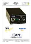
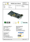
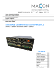
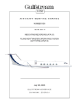
HALO ASCB-D/CANaerospace/ARINC825
Telemetry Interface System (TIS)
User’s Manual
HALO TIS User’s Manual Rev. 1.5
page 0 of 17
(C) Stock Flight Systems 2011
1
Telemetry Interface System Overview
The Telemetry Interface System (TIS) is a 19” rack mounted computer that interfaces to the HALO
aircraft Pilot or Copilot Side Secondary ASCB-D bus and a CANaerospace/ARINC 825 network.
The TIS performs the following functions in real time:
• ASCB-D data stream decoding and formatting
• ASCB-D data stream recording to external USB Harddisk
• CANaerospace/ARINC 825 data encoding/decoding
• Transmission of formatted ASCB-D data via a configurable 10/100/1000 Mbit/s Ethernet/
UDP/IP interface
• Bidirectional data translation between CANaerospace/ARINC 825 and the configurable
10/100/1000 MBit/s Ethernet/UDP/IP interface
The TIS uses the SuSE Linux 10.3 operating system with a customized 1000Hz realtime kernel
and provides the following computer interfaces:
• Keyboard/mouse (via USB)
• External recording Harddisk (via USB)
• VGA monitor
• Combined CD-ROM/DVD drive (rear side)
• Two additional USB ports (rear side)
The TIS operates from a single +18-36VDC aircraft supply and draws 3A of current at 28VDC. The
total weight of the unit is 10kg. The mechanical dimensions of the TIS unit are 435mm wide, 88mm
high and 370mm deep. The TIS will automatically start on power-up and cease operation on power-down without user intervention. System boot time is < 2 minutes. Figures 1 and 2 show the
TIS unit front and rear view.
Figure 1: HALO Telemetry Interface System (TIS-02A) front view
HALO TIS User’s Manual Rev. 1.5
page 1 of 17
(C) Stock Flight Systems 2011
Figure 2: HALO Telemetry Interface System (TIS-02A) rear view
2
ASCB-D Bus Interface
The cabling between the aircraft ASCB-D No. 1/2 Bus Test Interface Connector located on the
front right side behind the cockpit and the TIS is shown in Figure 3. As the ASCB-D bus is flight critical, the interface to the TIS uses two firewalls: A certified Honeywell ASCB-D Bus Coupler (Honeywell P/N 7027566-901) for electrical isolation and a Bus Isolation Unit for logical and electrical
isolation. The Bus Isolation Unit as well as the ASCB-D interface in the TIS do not contain any
transmitting devices and have read-only capability exclusively. The cable length between the Test
Interface Connector and the Bus Coupler is around 200mm so that the impact on the total length
of the Secondary Backup Bus is negeglible. The cable used for all connections is be according to
Honeywell ASCB-D specification (ECS P/N 322402). From the Bus Isolation Unit to the TIS, the
length of the bus is 10,8m but can also be extended to a maximum of 15m.
Ethernet
ca. 20cm
ASCB-D
ASCB-D Bus
Test Interface
Connector
ca. 3.4m
10m
Bus Isolation
Unit (BIU)
ASCB-D
Honeywell
Bus Coupler
ASCB-D
Telemetry
Interface
System (TIS)
28VDC
CANaerospace
ARINC 825
Figure 3: TIS ASCB-D Interface Overview
HALO TIS User’s Manual Rev. 1.5
page 2 of 17
28VDC
(C) Stock Flight Systems 2011
Figure 4 shows the Honeywell Bus Coupler which is installed very close to the ASCB-D test connector panel on the right side of the rear cockpit section of the aircraft. Figure 5 shows the Bus Isolation Unit (BIU).
Figure 4: Honeywell Bus Coupler
Figure 5: Bus Isolation Unit (BIU)
HALO TIS User’s Manual Rev. 1.5
page 3 of 17
(C) Stock Flight Systems 2011
7027566-901
Figure 6shows the firewall concept based on the Bus Coupler and Bus Isolation Unit. This combination provides 100% isolation and read-only access to the aircraft ASCB-D bus and prevents any
adverse effects on the safety critical side.
Figure 6: Firewall Concept based on Bus Coupler and Bus Isolation Unit
HALO TIS User’s Manual Rev. 1.5
page 4 of 17
(C) Stock Flight Systems 2011
The ASCB-D connector pinout of the Honeywell Bus Coupler is shown in Figure 7.
Bus Output, non-inverting (BUSOUT+)
n.c.
n.c.
Bus Input, non-inverting (BUSIN+)
Bus Input, non-inverting (BUSIN+)
5
4
3
2
1
9
8
7
6
(BUSOUT-) Bus Output, inverting
n.c.
(BUSIN-) Bus Input, inverting
(BUSIN-) Bus Input, inverting
ASCB-D
Figure 7: Honeywell Bus Coupler ASCB-D Connector Pinout
Both the aircraft side bus and the isolated bus going to the BIU are on the same (and only) ASCBD connector of the Bus Coupler. Also, the termination resistor for the aircraft bus stub is attached
to dedicated pins for this purpose.
The BIU ASCB-D connector pinout is shown in Figure 8. Only Pins 1 and 6 of the the ASCB-D
connector going to the Bus Coupler are used on the BIU. The ASCB-D connector on the BIU is a
9-pin male D-Sub and requires a 9-Pin female on the aircraft wiring to mate with the BIU.
n.c.
n.c.
n.c.
n.c.
Secondary Backup Bus, non-inverting (SEC+)
5
4
3
2
1
9
8
7
6
n.c.
n.c.
n.c.
(SEC-) Secondary Backup Bus, inverting
ASCB-D
Figure 8: Bus Isolation Unit ASCB-D Connector Pinout
On the output side of the BIU that connects to the TIS platform is a 9-Pin female D-sub with data
on Pins 1 and 6 (shown in Figure 9) requiring a male 9-Pin D-Sub on the wiring going to the TIS.
The TIS platform also has a 9-pin D-Sub that is male requiring a 9-pin female on the end connecting to the TIS. Pins 1 and 6 are used on both sides of the BIU and on the TIS 9-pin connector.
Only these two pins are used on these D-Sub connectors (all three of them).
Secondary Backup Bus, non-inverting (SEC+
n.c.
n.c.
n.c.
n.c.
1
2
3
4
5
6
7
8
9
(SEC-) Secondary Backup Bus, inverting
n.c
n.c.
n.c.
TIS
Figure 9: Bus Isolation Unit TIS Connector Pinout
HALO TIS User’s Manual Rev. 1.5
page 5 of 17
(C) Stock Flight Systems 2011
Power to the BIU is on a 6-pin circular Bendix 9429 PT02SE-10-6P connector. Power is on Pin A
(+28VDC) and Pin D (DC GND), all other pins are unused . The connector pinout is shown in Figure 10.
A
F
B
C
A = +28VDC
D = DC GND
E
D
Figure 10: Bus Isolation Unit Power Supply Connector Pinout
The wiring from the aircraft ASCB-D test interface connector to the Bus Coupler has to include the
required termination resistors for the Primary and Backup Bus. According to the Honeywell specification these resistors are 124Ω, 1% tolerance, 1/4W metal film resistors. The corresponding part
used for all 124Ω resistors in the TIS installation is DigiKey P/N MFR-25FBF-124R. The internal
circuit schematics of the Bus Coupler is shown in Figure 11.
Figure 11: Internal Circuit Schematics of the Honeywell Bus Coupler
The combination of the Honeywell Bus Coupler and the BIU allows non-certified, commercial-ofthe-shelf (COTS) equipment to interface to the ASCB-D bus. Both units are transformer coupled.
The BIU uses the same circuit and components as the Honeywell MAU NIC to interface to the
ASCB-D bus. Additionally, the BIU has on optically isolated one-way data path.
The wiring between the aircraft test connector, the Bus Coupler, the BIU and the TIS uses the Honeywell specified ASCB-D cable (ECS P/N 322402) and is shown in Figure 12. The total length of
the cable between the aircraft test connector and the Bus Coupler is 210mm, while the length of
the cable between the Bus Coupler and the BIU is 2,1m. After the BIU, the cable length to the TIS
is 10,8m but can easily be extended to 15m if required. Opening any connection between the BIU
and the TIS has absolutely no effect on the ASCB-D bus integrity at all.
Positronic P/N RD9S10000 connectors are used as the mating connectors for the No. 1/2 Bus Test
Interfacer and the Bus Coupler.
HALO TIS User’s Manual Rev. 1.5
page 6 of 17
(C) Stock Flight Systems 2011
BIU
S
1
6
Mission Interface
Panel Receptacle
BIU ASCB-D
Connector
124Ω
blue
white
0,8m
blue
P
1
6
Bus Coupler
S
Mission Interface
Panel Connector
1
6
P
blue
BIU TIS
Connector
S
1
6
8
4
124Ω
white
1 6 2 7 5 9
124Ω
blue
white
10,0m
ca. 3.4m
white
124Ω
124Ω
ca. 200mm
S
1
6
1
6
S
TIS Connector
No. 1/2 Bus
Test Interface
Figure 12: Wiring between Test Interface Connector, Bus Coupler, BIU and TIS
HALO TIS User’s Manual Rev. 1.5
page 7 of 17
(C) Stock Flight Systems 2011
3
Telemetry Interface System Connections and Operator Interface
The TIS is basically a rugged, SuSE-Linux-based PC with the corresponding I/O connections. For
operation within HALO, the following interfaces are used:
•
•
•
•
•
•
•
28VDC Power Supply Input
VGA Monitor Interface
USB Keyboard/Mouse Interface
USB Harddisk Interface
ASCB-D Interface
CANaerospace/ARINC825 Interface
10/100/1000 Mbit/s Ethernet Interface
The following interfaces are available in addition but are used only for maintenance/system upgrade purposes:
• DVD/CD-ROM Drive
• Reset Switch
• Power Switch
Figure 13 shows the TIS front panel layout with its corresponding connectors, Figure 14 the rear
panel. The VGA, USB and Ethernet connectors are according to standard PC specification. Power
to the TIS is on a 2-pin circular Amphenol AL00F11-2P connector requiring a AL06F11-2S mating
plug on the aircraft wiring. Power is on Pin A (+28VDC) and Pin B (GND), the connector pinout is
shown in Figure 15. The pinout of the ASCB-D connector and the CANaerospace/ARINC825 connector are shown in Figures 16 and 17.
Figure 13: TIS Front Panel Layout
Figure 14: TIS Rear Panel layout
A = +28VDC
B = DC GND
Figure 15: TIS Power Connector Pinout
HALO TIS User’s Manual Rev. 1.5
page 8 of 17
(C) Stock Flight Systems 2011
n.c.
n.c.
n.c.
n.c.
ASCB-D Bus, non-inverting (SEC+)
5
4
3
2
1
9
8
7
6
n.c.
n.c.
n.c.
(SEC-) ASCB-D Bus, inverting
ASCB-D
Figure 16: TIS ASCB-D Connector Pinout
n.c.
n.c.
n.c.
CAN Low
n.c.
5
4
3
2
1
9
8
7
6
n.c.
n.c.
CAN High
n.c.
CANaerospace/ARINC825
Figure 17: TIS CANaerospace/ARINC825 Connector Pinout
4
Telemetry System Operation
The TIS automatically boots after power is applied and shuts down when power is removed. No
user intervention is required for normal operation other than reading the continuously transmitted
UDP/IP packets from the Ethernet interface on the specified port numbers. Connecting a VGA monitor and a USB keyboard/mouse, however, monitoring the TIS operation and interacting with it
can be accomplished at any time.
4.1
System Startup
After the boot process has been completed, the KDE window manager is started and an automatic
login of “dlruser” (password “dlruser”) is performed. Within the KDE wndow manager, the “tis” application is started and continues to run until the system is shut down by removing the 28VDC power or by a corresponding operating system command (i.e. “poweroff”, “shutdown” or “halt”).
If an external USB hard disk has been detected during system startup, all received ASCB-D data
is stored on the hard disk until it is full. Using a 500GB disk formatted with the FAT32 file system,
more than 20 hours of flight data can be stored and used for post flight data analysis or playback
operations. Every 18.2 minutes, a new file with an increasing number in the filename extension is
generated and filled with data. The files have structured names as shown in the examples below:
• Tue_Dec__2_23_13_11_2008.01
• Tue_Dec__2_23_13_11_2008.02
HALO TIS User’s Manual Rev. 1.5
page 9 of 17
(C) Stock Flight Systems 2011
The user screen of the TIS available through the VGA connector after the completed boot process
is shown in Figure 18.
Figure 18: TIS screen after completed boot process
The “tis” application can be invoked with the “LIVE” shell script in the DLRTIS directory manually.
This script calls “tis” with the following parameters:
./tis tis.cfg Escape.le_reg nic.le_reg LIVE 192.9.200.255 3000 0
The blue parameter is the IP address on which the UPD packets will be sent, while the red parameter indicates the first UDP port number that will be used. One UDP packet consists of 256 parameters. If more parameters than 256 are specified in “tis.cfg”, these parameters are transmitted on
ascending UDP port numbers. Note that the IP address used in the LIVE shell script has to correspond with the general network settings of the Ethernet interface eth1 which may be modified
using the Linux “yast2” configuration tool.
Alternatively, the “tis” application can be invoked automatically after the TIS has booted. This is accomplished by the startup script “TIS.autostart” which is placed in the /home/dlruser/.kde/Autostart
directory. The content of “TIS.autostart” is:
[Desktop Entry]
Comment=
Comment[en_US]=
Encoding=UTF-8
Exec[$e]=’/home/dlruser/DLRTIS/tis’
GenericName=DLR TIS Application
GenericName[en_US]=DLR TIS Application
Icon=yast-kdump
MimeType=
Name=DLR TIS V1.0
Name[en_US]=DLR TIS V1.0
Path[$e]=$HOME
StartupNotify=true
Terminal=true
HALO TIS User’s Manual Rev. 1.5
page 10 of 17
(C) Stock Flight Systems 2011
TerminalOption=
TerminalOptions=/home/dlruser/DLRTIS/tis.cfg /home/dlruser/DLRTIS/Escape.le_reg /home/dlruser/DLRTIS/nic.le_reg LIVE 192.9.200.255 3000 0 --noclose
Type=Application
Version=1.0
X-DCOP-ServiceType=none
X-KDE-SubstituteUID=false
X-KDE-Username=
X-SuSE-translate=true
The “tis” application continuously displays the status of the processed ASCB-D data together with
the 12.5ms frame count and the value of the parameters specified in the “tis.cfg” file as shown in
Figure 19. Additionally, the remaining recording time and fill status of the external USB hard disk is
shown. With the start of the “LIVE” script, the “tis” application creates three logfiles in /tmp:
• /tmp/TIS_log.txt
• /tmp/config_log.txt
• /tmp/WRITE_THREAD_log.txt
These readable files contain all system messages about the boot process including the network
setup (TIS_log.txt), the content of the “tis.cfg” file (config_log.txt) and the data storage process on
the external USB hard disk (WRITE_THREAD_log.txt).
Note that data recorded on the external USB hard disk can also be played back using the “tis” application. A sample invocation of a recorded data playback is shown below:
./tis tis.cfg Escape.le_reg nic.le_reg Tue_Dec__2_23_13_11_2008.01 192.9.200.255 3000 0
During a playback, the logfile “/tmp/RECPLAY_log.txt” containing information about the playback
process is created. The recorded data is transmitted in realtime in the same way as it would be a
live stream. As all ASCB-D data of the attached bus is contained in the recording file, different configurations (that is, “tis.cfg” files) may be used than the one during the original flight.
Figure 19: “LIVE” shell script output
HALO TIS User’s Manual Rev. 1.5
page 11 of 17
(C) Stock Flight Systems 2011
4.2
Honeywell ASCB-D Configuration Files
The “tis” application reads the raw data stream from the attached ASCB-D bus and continuously
processes it using a periodic device driver. This periodic device driver requires the following files
generated by Gulfstream during the avionics system configuration of the aircraft:
•
•
•
•
Planeview_Configuration_Data.mdb
Planeview_ASCB_Data.mdb
Escape.le_reg (from the Escape MODULE/TISPROC/APPBIN directory)
nic.le_reg (from any Escape MODULE directory)
These files, generated using original Honeywell tools, will change from software load to software
load. Therefore, the TIS needs to be upgraded each time a new software load is installed in the aircraft. While the “Escape.le_reg” and “nic.le_reg” files can be used as is, the .mdb database files
have to be converted by ICS/Stock Flight Systems into an XML file using the format as specified in
Appendix A of this manual. The name of this master ASCB-D bus configuration file is
• HALOMasterConfig.xml
A maximum of 4096 parameters may be selected from this file and be used to create flight test
specific configuration files of the same format. The parameters specified in the flight test specific
file used for a mission will be continuously read from the ASCB-D bus, converted into engineering
data and transmitted in one or more UDP/IP packets every 12.5ms. The data renewal rate of 80
per second is fixed and directly driven by the ASCB-D bus data flow.
The flight test specific configuration file has to be converted into a special format for the “tis” application using a converter program called “xml2cfg”. The resulting file has the name “tis.cfg” and
contains all information required by the “tis” application to generate the appropriate UDP/IP pakkets. “xml2cfg” reads the XML configuration file, displays the detected functions and processes all
parameters to create “tis.cfg”. A sample XML configuration file is shown below:
<?xml version="1.0" encoding="UTF-8"?>
<TISConfig version="1.0" name="HALO Demo Config">
<Bus name="ascbd" id="0">
<Function name="ADS" description="Air Data System">
<Parameter name="baroAltitude1">
<Handle function="4" instance="1" channel="0" identifier="4"/>
<Signal data_type="Float" unit="ft" rate="50.00" min="-2100.00" max="61000.00" resolution="0.50" data_bits="17"/>
<Information group_name="airData50msec" group_desc="50 msec Air Data Parameter Group" signal_desc="Pilot/Baro Altitude/>
</Parameter>
<Parameter name="baroAltitude1">
<Handle function="4" instance="2" channel="0" identifier="4"/>
<Signal data_type="Float" unit="ft" rate="50.00" min="-2100.00" max="61000.00" resolution="0.50" data_bits="17"/>
<Information group_name="airData50msec" group_desc="50 msec Air Data Parameter Group" signal_desc="Pilot/Baro Altitude/>
</Parameter>
<Parameter name="staticAirTemperature">
<Handle function="4" instance="1" channel="0" identifier="16"/>
<Signal data_type="Float" unit="Deg C" rate="50.00" min="-105.00" max="65.00" resolution="0.00" data_bits="17"/>
<Information group_name="airData50msec" group_desc="50 msec Air Data Parameter Group" signal_desc="Static Air Temp/>
</Parameter>
<Parameter name="totalAirTemperature">
<Handle function="4" instance="1" channel="0" identifier="23"/>
<Signal data_type="Float" unit="Deg C" rate="50.00" min="-80.00" max="105.00" resolution="0.00" data_bits="17"/>
<Information group_name="airData50msec" group_desc="50 msec Air Data Parameter Group" signal_desc="Total Air Temp/>
</Parameter>
<Parameter name="pressureAltitude">
<Handle function="4" instance="1" channel="0" identifier="24"/>
<Signal data_type="Float" unit="ft" rate="50.00" min="-2100.00" max="61000.00" resolution="0.50" data_bits="17"/>
<Information group_name="airData50msec" group_desc="50 msec Air Data Parameter Group" signal_desc="Pressure Altitude/>
</Parameter>
</Function>
<Function name="IRS" description="Micro Inertial Reference System">
<Parameter name="pitchAngle">
<Handle function="7" instance="1" channel="0" identifier="12"/>
<Signal data_type="Float" unit="Deg Angle" rate="12.50" min="-180.00" max="180.00" resolution="0.00" data_bits="19"/>
<Information group_name="irs12msec429" group_desc="12 msec A429 Inertial Reference System Data" signal_desc="Pitch Angle/>
</Parameter>
<Parameter name="pitchAngle">
<Handle function="7" instance="1" channel="1" identifier="12"/>
<Signal data_type="Float" unit="Deg Angle" rate="12.50" min="-180.00" max="180.00" resolution="0.00" data_bits="19"/>
<Information group_name="irs12msec429" group_desc="12 msec A429 Inertial Reference System Data" signal_desc="Pitch Angle/>
HALO TIS User’s Manual Rev. 1.5
page 12 of 17
(C) Stock Flight Systems 2011
</Parameter>
<Parameter name="pitchAngle">
<Handle function="7" instance="2" channel="0" identifier="12"/>
<Signal data_type="Float" unit="Deg Angle" rate="12.50" min="-180.00" max="180.00" resolution="0.00" data_bits="19"/>
<Information group_name="irs12msec429" group_desc="12 msec A429 Inertial Reference System Data" signal_desc="Pitch Angle/>
</Parameter>
<Parameter name="pitchAngle">
<Handle function="7" instance="2" channel="1" identifier="12"/>
<Signal data_type="Float" unit="Deg Angle" rate="12.50" min="-180.00" max="180.00" resolution="0.00" data_bits="19"/>
<Information group_name="irs12msec429" group_desc="12 msec A429 Inertial Reference System Data" signal_desc="Pitch Angle/>
</Parameter>
<Parameter name="pitchAngle">
<Handle function="7" instance="3" channel="0" identifier="12"/>
<Signal data_type="Float" unit="Deg Angle" rate="12.50" min="-180.00" max="180.00" resolution="0.00" data_bits="19"/>
<Information group_name="irs12msec429" group_desc="12 msec A429 Inertial Reference System Data" signal_desc="Pitch Angle/>
</Parameter>
<Parameter name="pitchAngle">
<Handle function="7" instance="3" channel="1" identifier="12"/>
<Signal data_type="Float" unit="Deg Angle" rate="12.50" min="-180.00" max="180.00" resolution="0.00" data_bits="19"/>
<Information group_name="irs12msec429" group_desc="12 msec A429 Inertial Reference System Data" signal_desc="Pitch Angle/>
</Parameter>
</Function>
</Bus>
</TISConfig>
The execution of the “xml2cfg” converter program, creating the “tis.cfg” file will generate the following output:
./xml2cfg DemoConfig.xml
Input file DemoConfig.xml opened
-------------------------------Bus name = ascbd, id = 0
Function name = ADS
Function name = IRS
15 Parameters written to tis.fg, closing file.
The NIC.le_reg and Escape.le_reg files together with the flight test specific “tis.cfg” have to be placed into the DLRTIS directory (where the “tis” application is started from). Upon program start, “tis”
reads all these files to configure its ASCB-D interface and data processing.
4.3
UDP/IP Packet Format Description
The UDP/IP packets transmitted over the Ethernet interface by the “tis” application every 12.5ms
have a fixed length of 1040 bytes each. The packet format consists of 32-bit wide parameters organized in Little Endian data representation. The Packet format is shown below:
Packet Size
ASCB-D Frame Number
Packet Identifier
Parameter 0
Parameter 1
Parameter n - 1
Parameter n
CRC
The first 4 bytes of the packet form a 32-bit integer value indicating the packet size (0x00000410 =
1040) while the following 4 bytes contain the ASCB-D frame number relating to the parameter. The
Packet Identifier provides information about the number of the packet with respect to the total number of packets transmitted based on the equation: Total_Frame_Count * 100 + Frame_Number.
HALO TIS User’s Manual Rev. 1.5
page 13 of 17
(C) Stock Flight Systems 2011
The last 4 bytes form a 32-bit CRC for the entire UDP packet. This CRC is a 32-bit ANSI 3.66 CRC
with a generator polynomial of 0xedb88320 or:
X32+X26+X23+X22+X16+X12+X11+X10+X8+X7+X5+X4+X2+X1+X0
Each UDP packet holds 256 parameters, each 32 bits wide which are in the order as specified
through the XML configuration file. For every 256th parameter, a new packet with a different port
number (in ascending order) is generated and transmitted. That means that for 513 parameters,
three UDP packets with a size of 1040 bytes each will be generated. Unused parameters in the
last packet are padded with zeroes.
5
Appendix A: XML Configuration File Format Description
The TIS Configuration uses the XML file format which is human readable and directly compatible
with word processing tools (for more information, please refer to www.w3.org). TIS Configuration
files shall have the suffix “.xml”.
The file format uses XML tags to identify the information elements. Tags are case insensitive
ASCII text strings embraced by <> brackets. Unrecognized tags within a TIS Configuration including all lines belonging to it shall be ignored. The data types used for element attributes are:
5.1
Data Type
Description
float
ASCII text string describing a single-precision
floating-point value according to IEEE7541985
int
ASCII text string describing a signed integer
value
string
ASCII text string of variable length (maximum
256 Bytes)
TIS Config Element
The TIS Config element uniquely identifies a TIS Configuration file.
Element:
Max Instances:
Parent:
Optional:
Attributes:
<TISConfig> ... </TISConfig>
1
None
No
Attribute
Name
Optional
Type
Description
version
no
string
File version in the format: Major.Minor
name
no
string
Clear text name of the profile
HALO TIS User’s Manual Rev. 1.5
page 14 of 17
(C) Stock Flight Systems 2011
5.2
Bus Element
The bus element contains the bus specification.
Element:
Max Instances:
Parent:
Optional:
Attributes:
<Bus> ... </Bus>
Unlimited
TISConfig
No
Attribute
Name
Optional
Type
Description
name
no
string
Clear text name of the bus (either “ascbd” or
“can”)
id
no
int
Identifier of the bus (used to distinct between
multiple buses of the same name). The default value is “0”.
5.2.1 Function Element
The function element contains a function.
Element:
Max Instances:
Parent:
Optional:
Attributes:
<Function> ... </Function>
Unlimited
Bus
Yes
Attribute
Name
Optional
Type
Description
name
no
string
Clear text name of the function
descriptio
yes
string
Description of the function in clear text
5.2.1.1 Parameter Element
The parameter element defines a TIS parameter.
Element:
Max Instances:
Parent:
Optional:
Attributes:
<Parameter> ... </Parameter>
Unlimited
Function
Yes
HALO TIS User’s Manual Rev. 1.5
page 15 of 17
(C) Stock Flight Systems 2011
Attribute
Name
Optional
Type
Description
name
no
string
Clear text name of the parameter
5.2.1.1.1 Handle Element
The handle element defines a parameter handle.
Element:
Max Instances:
Parent:
Optional:
Attributes:
<Handle> ... </Handle>
Unlimited
Parameter
Yes
Attribute
Name
Optional
Type
Description
function
no
int
Function identifier of the parameter associated with the handle
instance
no
int
Instance of the parameter associated with
the handle
channel
no
int
Channel of the parameter associated with the
handle (“0” = pilot side, “1” = copilot side)
identifier
no
int
Identifier of the parameter associated with
the handle
5.2.1.1.2 Signal Element
The signal element defines the signal associated with a parameter.
Element:
Max Instances:
Parent:
Optional:
Attributes:
<Signal> ... </Signal>
Unlimited
Parameter
Yes
Attribute
Name
Optional
Type
Description
data_type
yes
string
Clear text name of the signal data type
HALO TIS User’s Manual Rev. 1.5
page 16 of 17
(C) Stock Flight Systems 2011
Attribute
Name
Optional
Type
Description
unit
yes
string
Clear text name of the signal unit
rate
yes
float
Update rate of the signal in milliseconds
min
yes
float
Minimum value of the signal in engineering
units
max
yes
float
Maximum value of the signal in engineering
units
resolution
yes
float
Resolution of the signal in engineering units
data_bits
yes
int
Number of valid data bits for this signal within
the 32-bit parameter (rightmost arrangement)
5.2.1.1.3 Information Element
The information element defines additional information associated with a parameter.
Element:
Max Instances:
Parent:
Optional:
Attributes:
<Information> ... </Information>
Unlimited
Parameter
Yes
Attribute
Name
Optional
Type
Description
group_name
yes
string
Clear text name of the signal group name
group_desc
yes
string
Clear text description of the signal group
signal_desc
yes
string
Clear text description of the signal
HALO TIS User’s Manual Rev. 1.5
page 17 of 17
(C) Stock Flight Systems 2011