
1
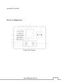
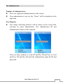
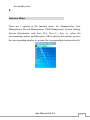
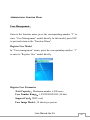
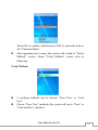
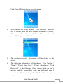
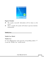
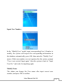
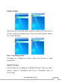
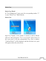
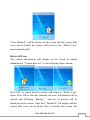
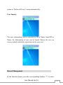
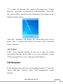
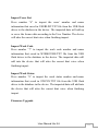
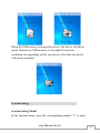
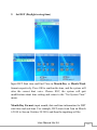
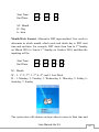
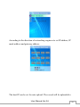
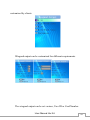
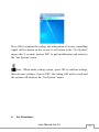
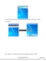
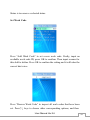
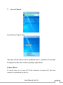
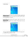
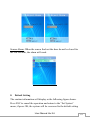
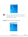
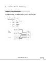
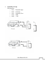
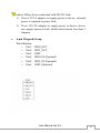
Face Recognition Access Control & Attendance System User Manual July 2010 User Manual Ver.2.6 1 Table of Contents Product Overview .......................................................... 4 General Introduction ................................................................. 4 Features.................................................................................... 4 Device Configuration................................................................ 5 Installation Instruction ......................................................... 9 Startup .............................................................................. 11 Set Administrator and operation ................................ 13 Set Administrator.................................................................... 13 Enter to Set Administrator Model ....................................... 13 Set Administrator............................................................... 14 Modify or Delete Administrator ......................................... 16 Administrator Verification ................................................. 18 Function Menu .................................................................. 19 Administrator Function Menu ................................................. 20 User Management ............................................................. 20 Modify User ...................................................................... 25 Delete User ....................................................................... 28 Record Management .......................................................... 30 USB Management ............................................................. 32 System Setting................................................................... 38 System Information ........................................................... 62 Auto Test ........................................................................... 64 For Common User .................................................................. 68 User Manual Ver.2.6 2 Face Recognition ............................................................... 68 User No. & Face Recognition ............................................ 70 Card Recognition............................................................... 70 Card & Face Recognition................................................... 70 Authentication Successfully............................................... 71 Appendix ...................................................................... 73 Technology Specification .................................................. 73 Terminal Blocks Description ............................................. 74 Caution ............................................................................. 78 Caution:The functionalities and contents shown in this manual may different from the actual product please refer to the actual product. Please forgive us to simplify some words because of limited display on the screen, such as: Admin. refers to Administrator; Recog. refers to Recognition; No. refers to Number. User Manual Ver.2.6 3 Product Overview General Introduction Face ID is industry first embedded facial recognition system with leading “Dual Sensor” Facial Recognition Algorithm, FAR<0.0001% which makes facial recognition more faster and accurate, different source-light technology enable the system works well under different environment for access control and time attendance application. Features Embedded facial recognition system: Adopt US advanced DSP technology keeps processing and matching right on the device; Standalone application as time attendance access control, user identification Accurate and Fast Identification: Industrial Leading “Dual Sensor” Facial Recognition Algorithm, FAR<0.0001%;1: Many up to 500 users less than 1 second. Large user and log capacity: User capacity from 500 users (5000 card users);Over 150,000 logs and optional image capacity over 70,000. Reliable performance under different environments:Different source-light Technology.;The system can work in different light condition even in the dark;Over three years Chinese market testing. Flexible I/O interfaces Internet Protocol based enables LAN or Network deployment;USB Host for User data upload or download via USB flash driver. Wiegand input/output makes system compatible with different access control panel. User friendly design: 3.5 inch color screen for face positioning; Contactless authentication for the ultimate in hygienic; voice User Manual Ver.2.6 4 prompts for guide. Device Configuration Front View Figure User Manual Ver.2.6 5 Right View Figure Back View Figure (1) 3.5 inch TFT Color LCD Display the function menu and user images information. (2) Navigation Key Press ↑/↓ k eys to select the fu nction th at you want to p erfo rm User Manual Ver.2.6 6 in the menu. (3) Area for swiping RFID Card Swipe RFID card around this area. (4) Left sensor Capture the face images. (5) Right sensor Capture the face images. (6) LED Located around sensors, provide enough light for sensors to capture face images. (7) OK-Confirmation key If there is prompt information popup or options need to be confirmed, press OK to confirm the operation. (8) ESC----Return/Cancel key Under the selection prompt or input states, press ESC to cancel the operation. When the system under the sub-interface, press ESC to exit the current interface, and return to the previous interface. (9) Index/ Numeric key Index list key : Under the menu state, each number corresponding to each option in the menu, press any number key to select and operate the corresponding function in the menu. Numeric key:Under the input state, press the Numeric key 0~9 to input numbers or letters. (10) Power key User Manual Ver.2.6 7 To turn on or turn off the device (11) Function key (F1 / F2 / F3) 3 function keys to provide a quick switch method for work status. Press F1 to call work status list; Press F2 to switch work status to “On Duty”; Press F3 to switch work status to “Off Duty” (12) Backspace key Under the input state, press this key to delete a number, the cursor will go back a space. (13) MENU key Press MENU key to shift to the Administrator Verifying interface, user can operate the system as an administrator after verified by the system. (14) Reset button The device will be restarted by pressing the key in this hole (15) USB port Connect with USB flash driver, after verified by an administrator, user can import or export data by using the USB flash driver. (16) Speaker Broadcast system voice or information. (17) Terminal blocks Terminal blocks support several communication ports and DC power port. (18) Device installation mounting plate It is used for fixing the device on the wall User Manual Ver.2.6 8 (19) Removal alarm trigger A trigger to control status of the removal alarm (20) Power adapter port Power adapter port. 12V/1A DC adapter (standard). (21) Network cable port Insert network cable in the network cable port, the device will be connected with PC for any management operation with the software Installation Instruction Please drill four holes on the wall according to diagram below. User Manual Ver.2.6 9 (Device installing diagram) Unconnected with door controller Insert the standard power adapter plug into the power port which is placed at the left slot in the back of the device. Connected with access controller Connect the cable with the terminal blocks through the backboard as the installation diagram shown. Plug the RJ45 crystal port of network cable into the network cable port which is located at left top side in the back of device; Install the Mounting plate, the vertical distance could be 1.15 meters between the two below level holes and ground. Fixed the Mounting plate on the wall and please ensure the backboard is horizontal and vertical from the ground, and it need to be stuck on the wall; User Manual Ver.2.6 10 Insert the fixing holes at the back of device into the protrude pins which are placed at the Mounting plate, then press it down softly, keep the device hanging on the Mounting plate and stick it with the backboard, then fix the screw at the bottom of device. Make sure all connection finished and correct, then power on the device. Startup Following figure will be shown after power on the device; it is also the standby interface. Current date, week, time will be shown on the screen. When record capacity reaches up to 85%, capacity percent will be shown on the screen to remind the administrator. At that moment, the administrator should export or clear some data from the device. User Manual Ver.2.6 11 If the SD card is not in the device, the information of ‘No SD’ will be shown on the screen. User Manual Ver.2.6 12 Set Administrator and operation Set Administrator Enter to Set Administrator Model First entrance: Start the system at the first time, the administrator has not been set yet. Press MENU to enter Functions Menu, and then press 1 to Set Administrator operation model, the following picture will be shown on the screen. Caution:Please set one administrator at least when start to use this device, because for the security reason all operations need to be controlled by the administrator. Normal entrance: After setting an administrator, press MENU to enter Administrator Verifying model, function menu will be displayed after verification success. User Manual Ver.2.6 13 Set Administrator Number of Administrators There are eight unset administrators in the system. If an administrator is not set, the “Unset” will be displayed at the right side. Face Register Face image collecting interface will be shown on the screen after selecting an unset administrator. The Administrator ID and Administrator Name will be required. There are three method to verify, ID and Pin; ID and Face or Card and Face. ID and Pin will need the administrator input the ID and password. User Manual Ver.2.6 14 During the face enrollment, white frame means the face position is not good, green frame means user’s face position is good for enrollment. Card and Face require user swipes card and then register the user`s face As soon as the face is detected by sensors, the green line frame will be shown on the screen, the system will mark user’s face outline character and process user’s face information with digital automatically. The processing bar will be shown at the bottom of screen to display the process of the enrollment. The prompt information will also be displayed to remind user to “watch sensors, lower your head, raise your head, and turn head to left, turn head to right…” User Manual Ver.2.6 15 Hint:the system increases accurate rate of recognition to avoid the same administrator registers themselves again on another administrator ID. Register Finished The register successful information will be shown on the screen. After 2 seconds, the system will return to previous interface automatically. Modify or Delete Administrator Enter the “Set Administrator” menu. Register Again Select the corresponding administrator to modify; User Manual Ver.2.6 16 Select “Register Again” in the menu; Enroll face template again; Modify and Delete Administrator Select the corresponding administrator to delete or modify; Select “Modify or Delete Administrator”; Press OK to confirm; “Finished” will be shown on the screen; after 2 seconds, the system will return to “Set Administrator” menu. Hint:If only one administrator remained, it will be forbidden to delete, as the following figure shown, and the wrong voice can be heard. After 2 seconds, the system will return to “Set Administrator” menu. User Manual Ver.2.6 17 Administrator Verification Press MENU to enter to administrator verifying model. ID and Pin, ID and Face or Card and Face will be required. After face verification successful, administrator could enter the menu to do more settings as register user, set system. User will be verified during 5 seconds as a cycle for administrator verifying. If verification failed after 3 cycles continuously, “Recognition Failed” will be shown as the following figure, the wrong voice prompt can be heard. After 2 seconds, it will return to User Manual Ver.2.6 18 the standby state. Function Menu There are 7 options in the function menu: Set Administrator, User Management, Record Management, USB Management, System Setting, System Information, and Auto Test. Press ↑/↓ keys to select the corresponding option, and then press OK to operate this option, or press the corresponding number to operate the corresponding function directly. User Manual Ver.2.6 19 Administrator Function Menu User Management Enter to the function menu, press the corresponding number ”2” to enter “User Management” model directly. In this model, press ESC to quit and return to the “Function Menu”. Register User Model In “User management” menu, press the corresponding number ”1” to enter to “Register User” model directly. Register User Parameter Total Capacity:Maximum number is 500 users User Number Range:1-99999999999999 (14 bits) Support Card:ID/IC card Face Image Model:18 sheets per person User Manual Ver.2.6 20 Caution:User Number is formed by nature number, and it cannot repeat, “0” cannot be used in front of the job number, for example: 0020, it will be recognized as 20. Register User Input User Number In the “Register User” model, there will be an editing frame shown on the screen, input user’s ID Number in it as the following figure shown, the device will inspect whether this user number is existed in the database or not. Input Name Input available Name in the following interface. Text field can accept lower/upper letters, blank and dot characters. Press “MENU” key can switch model between lower and upper letter. User Manual Ver.2.6 21 Press OK to confirm, and then press ESC to quit and return to the “Function Menu”. After inputting user’s name, the system will switch to “Verify Method”, screen. About “Verify Method”, please refer to following: Verify Method 2 verifying methods can be chosen: “Face User” or “Card User” Choose “Face User” methods, the system will go to “Face” or “Card and Face” interface. User Manual Ver.2.6 22 Choose “Card User” methods, the system will go to “Card” or “Card and Photo” interface. Choose “Card”, “Card and Photo” or “Card and Face” methods, the system will request user to swipe the RFID card. Press ESC to cancel card registration. After finishing card registration, the system will go to Face Hint:Face recognition for normal user; Card recognition for temporary user; Card and Face recognition for high security level; After “Verify Method”, the system will go to face registration; the procedure is the same to face registration in page 9. If choose “Card”,“Card and photo” or “Card and Face” mode in the previous step, then the system will ask user to register User Manual Ver.2.6 23 Card. Press ESC to return to the main menu. After choose one verify method, “User Privilege” interface will be shown, there are three options, Attendance &Access, Attendance only or Access only. Press OK to confirm and press ESC to ignore as alternative. The register successful information will be shown on the screen. The following information will be shown: “User Number”, “Name”, “Permit Open Door”, “Permit Attendance”, ”Card Registered” as the following figure shown based on user’s options, and the correct hint voice can be heard; after 2 seconds, it will return to “Input User No.” interface to register next user. User Manual Ver.2.6 24 Register Finished The register successful information will be shown on the screen. After 2 seconds, the system will return to previous interface automatically. Modify User Modify User Model Modify User In “User Management” menu press the corresponding number “2” to enter the “Modify User” model directly. User Manual Ver.2.6 25 Input User Number In the “Modify User” model, input corresponding User’s Number to modify, the system will inspect the corresponding information in the database automatically, press OK, then enter the “Modify User” menu; if that user number was not registered in the system, prompt “User is not existed, Input again”, then the system is back to “Input User No.” and waits for inputting again. Modify Name The admin can change the User name after input correct user number, and press OK to confirm. User Manual Ver.2.6 26 Modify Method When the user re-enter the name, then the system will let the user to choose verification method again. About the detail options, please see “Verify Method”. Face / Card Registration According to a method user chose, then to do the face or card registration. Modify Privilege The privilege can be changed in Modify Privilege. There are three options, which is Attendance and Access, Attendance only or Access only. User Manual Ver.2.6 27 Delete User Delete User Model In “User Management” menu, press the corresponding number “3” to enter “Delete User” Model directly. Delete User Input User Number, if the number is existed, it will be deleted; otherwise, that information: “User is not existed” will be shown on the screen and it will quit automatically. Press OK to confirm, “Confirm Delete?” will be displayed, and utter the hint voice, press OK again to delete the selected user. User Manual Ver.2.6 28 “User Deleted!” will be shown on the screen and the correct hint voice can be heard, the system will return to the “Delete User” menu automatically. Delete All Users The caution information will display on the screen to remind administrator “Cannot Recover!” as the following figure shown: Press ESC to cancel and the system will return to “Delete User” menu. Press OK to start this function, all users’ information will be cleared and “Deleting…Waiting…” and rate of process will be displayed on the screen. After that, “Finished” will display and the correct hint voice can be heard, after 2 seconds, the system will User Manual Ver.2.6 29 return to “Delete all Users” menu automatically. User Inquiry The user information can be searched by ID or Name. Input ID or Name, the information of user can be found. Choose the user on screen, modify and delete operation can be carry out. Record Management In the function menu, press the corresponding number ”3” to enter User Manual Ver.2.6 30 to “Record Management” model directly. In this model, press ESC to quit and return to the “Function Menu”. Record Inquiry In “Record management” menu, press the corresponding number “1” to enter the “Record Inquiry” model, and press ESC to quit and return to the “Function Menu”. The records can be searched by ID or Name. Choose one of them, the “Record Inquiry” interface will be shown as below. Input User ID or User Name and Start time/End time to get users’ record. Delete all Record Model In “Record Management” menu, press the corresponding number User Manual Ver.2.6 31 “2” to delete all Records. The system will prompt user “Cannot Recover!”, press ESC to return to the “Function Menu”. Press OK, the record will be cleared, the hint information will display as the following figure shown. After that, “Finished” will display, the correct hint voice can be heard, after 2 seconds, the system will return to the “Function Menu” interface. Auto Upload Select “Auto Upload” function to turn on or turn off records auto-upload function. If the status is on, every attendance record will be transmitted to a server with specified IP address. USB Management In the function menu, press the corresponding number “4” entry the ‘insert USB Disk’ interface. Enter “USB management” model directly. User Manual Ver.2.6 32 1. The record and user information can be imported or exported in this model. 2. Work code and status also can be imported from here. 3. The firmware can be upgraded directly via USB flash driver. USB Import or Export Model Under the system standby interface, insert USB flash driver, the system will start administrator verifying function automatically, after the verification, the USB flash driver function menu as following figure shown. Remove the USB flash driver or presses ESC, the system will return to the standby interface. Caution:Due to the capability of chip is limited, a few models of USB flash drive could not be compatible with this device. User Manual Ver.2.6 33 USB flash driver operation Export records Press number “1” to export all attendance records and access records from the device, the procedure percent will be shown on the screen, the data exported will form a new file named TIME.TXT in the USB flash driver. After that, there will be successful prompt information display, and utter the correct hint voice. After 2 seconds, system will return to the “Function Menu”. User Manual Ver.2.6 34 Export Part Users Press number “2” to export the selected user’s information and face images files, input his User Number and press OK to confirm, and then input the next one’s User Number. Press ESC to finish the selection, the system will export the information and face images files you had selected before. During the exporting process, the procedure percent will be shown on the screen. There will be successful prompt information display when it finished, and utter the correct hint voice. After 2 seconds, the system will return to the “Function Menu”. The data exported will form a new file named USER.TXT in the USB flash driver. Export All Users Press number “3” to export all users’ information and face images files. During the exporting process, the procedure percent will be shown on the screen. There will be successful prompt information display when it finished, and utter the correct hint voice. After 2 seconds, system will return to the “Function Menu”. The data exported will form a new file named USERALL.TXT in the USB flash driver. Import Part Users Press number “4” to import the users’ information and face images saved in USER.TXT file from the USB flash driver to the database in the device. During the importing process, the procedure percent User Manual Ver.2.6 35 will be shown on the screen. The imported data will add up or cover the former data according to the Job Number. There will be successful prompt information display when it finished, and utter the correct hint voice. After 2 seconds, system will return to the “Function Menu”. Import All Users Press number “5” to import the users’ information and face images saved in USERALL.TXT file from the USB flash driver to the database in the device. During the importing process, the procedure percent will be shown on the screen. The imported data will add up or cover the former data according to the User Number. There will be successful prompt information display when it finished, and utter the correct hint voice. After 2 seconds, system will return to the “Function Menu”. Caution: The imported file must be USER.TXT or USERALL.TXT which is exported from the device, and the contents must not be modified, unless there will be a default. User Manual Ver.2.6 36 Import Users List Press number “6” to import the users’ number and name information that saved in USERLIST.TXT file from the USB flash driver to the database in the device. The imported data will add up or cover the former data according to the User Number. The device will utter the correct hint voice when finishing import. Import Work Code Press number “7” to import the work code number and name information that saved in WORKCODE.TXT file from the USB flash driver to the database in the device. The imported data will add into the device that will utter the correct hint voice when finishing import. Import Work Status Press number “8” to import the work status number and name information that saved in STATUS.TXT file from the USB flash driver to the database in the device. The imported data will add into the device that will utter the correct hint voice when finishing import. Firmware Upgrade User Manual Ver.2.6 37 When the USB memory is inserted to device, the device will check up the firmware in USB memory. If the right file has been confirmed, the upgrading will be carried out. After that, the device will restart automatic. System Setting System Setting Model In the function menu, press the corresponding number “5” to enter User Manual Ver.2.6 38 “System Setting” model directly; Press ESC to quit and return to the “Function Menu” interface. Hint:When under system setting, press “OK” to confirm the setting, then do more settings; If press “ESC”, the setting will not be saved and the system will return to the “System Setting” menu. System Setting 1. Set Date and Time User Manual Ver.2.6 39 Set Date and Time Input combined numbers in Y/M/D frames respectively, cursor will jump to the next frame when user finished in the last frame, cursor will wink in which it locate, and inspect the number’s validity automatically. Press OK to confirm the time, and the system will utter the correct hint voice, it will return to the “Set System” menu after 2 seconds. Press ESC, the system will quit modification and return to the “Set System” menu. The system time can be set into 9 formats in order to fit different countries time formal. User Manual Ver.2.6 40 2. Set DST (Daylight saving time) Input DST Start time and End Time in Month-Day or Month-Week format respectively. Press OK to confirm the time, and the system will utter the correct hint voice. Choose ESC, the system will quit modification about time setting and return to the “Set System Time” menu. Month-Day Format: input month, date and time information for DST start time and end time. For example, DST starts from 2am on March 6 2010 to 2am on October 20 2010, and then the inputting will be: User Manual Ver.2.6 41 Start Time: End Time: 03 M 03 M 06 D 06 D 02 h 02 h M - Month D - Day h - hour Month-Week Format: Alternative DST input method. User needs to determine in which month, which week and which day is DST start time and end time. For example, DST starts from 2am in 3rd Sunday on March 2010 to 2am in 1st Sunday on October 2010, and then the inputting will be: Start Time: End Time: 03 M 03 W 07 D 02 h 10 M 01 W 07 D 02 h M – Month W – 1: 1st; 2: 2nd; 3: 3rd; 4: 4th; and 5: Last Week D – 1: Monday; 2: Tuesday; 3: Wednesday; 4: Thursday; 5: Friday; 6: Saturday; 7: Sunday. The system time will advance an hour when it comes to Start time and User Manual Ver.2.6 42 will recover when it comes to End time. 3. Set Volume Press the corresponding number key to choose “High, Middle, Low, Mute” level, or press↑/↓ keys to shift the op tions, then press OK to confirm the selection, the device will utter the correct hint voice(in the last set volume level), it will return to the “Set System” menu after 2 seconds. Choose ESC, the system will quit modification about the volume setting and return to the “Set System” menu. User Manual Ver.2.6 43 4. Set Power Button The power button can control the button in the keypad whether available. And device has an power on and off schedule. There are two time points can be set. One opening time and one closing time can control the device open and close automatically. User Manual Ver.2.6 44 5. Set Communication Network Setting User Manual Ver.2.6 45 According to the direction of networking engineer to set IP address, IP mask address and gateway address. The host IP can be set for auto upload. The record will be uploaded to User Manual Ver.2.6 46 this IP computer. The communication password is not necessary. That is used for increasing the security level. The password will be inputted when the device connected with computer. Press OK to confirm the setting, the complete networking information User Manual Ver.2.6 47 will be shown on the screen; it will utter the correct hint voice and restart the device automatically. Wiegand Output According to the direction of access controlling engineer to set the format of the access controller port in the device, it can support the following setting: Wiegand 26 or 26 with site code and Wiegand 34 or 34 with site code as the following figure shown. Also it can be User Manual Ver.2.6 48 customized by clients. Wiegand output can be customized for different requirements. The wiegand output can be set various, User ID or Card Number. User Manual Ver.2.6 49 Press OK to confirm the setting, the information of access controlling signal will be shown on the screen, it will return to the “Set System” menu after 2 seconds, presses ESC to quit modification and return to the “Set System” menu. Hint:When under setting system, press OK to confirm settings, then do more settings, if press ESC, the setting will not be saved and the system will return to the “Set System” menu. 6. Set Attendance User Manual Ver.2.6 50 Set Interval Set time range or attendance interval. The system will record attendance based on Interval Time. Interval is 2, means the system will only record the first attendance log and other logs not within 2 minutes for each user. Notice: Interval Time Range: 0-255; Value 0 means set interval function is not being used. Set Bell Alarm User Manual Ver.2.6 51 In order to give the user a tip when specifically time, the device offers five bells. The admin can set different sound from eight bell rings to divide User Manual Ver.2.6 52 different time point. Set Work Status The System already has two statuses as default setting: 1.on duty 2.off duty. Choose Add Status to add new status. The system totally can support 8 statuses. The status also can be start automatically. Related Parameter Status ID Range:1-255 Status Name:18 sheets per status View all status through pressing “Browse Status”. The system have set “on duty” time for 9:00 and “off duty” time for 18:00 as default. Press “Status Switch Time” to change corresponding status time. User Manual Ver.2.6 53 Press “↓”k ey to select the corresponding status in the recognition and Standby interface. User Manual Ver.2.6 54 Modify Status is to amend an existing status in the device, and Delete User Manual Ver.2.6 55 Status is to remove a selected status. Set Work Code Press “Add Work Code” to set a new work code. Firstly, input an available work code ID, press OK to confirm. Then input a name for this shift to define. Press OK to confirm the setting and it will utter the correct hint voice. Press “Browse Work Code” to inspect all work codes that have been set. Press ↑/↓ keys to choose other corresponding options, and then User Manual Ver.2.6 56 press OK to operate this option, or press the corresponding number key to operate the corresponding function directly. Related Parameter: Work Code ID Range:1-9999 Work Code Name:18 sheets per position Hint:If the user select “Open Work Code” model, the user has to select corresponding work code after recognizing successfully. User Manual Ver.2.6 57 7. Access Control Lock Driven Time(1-10s) The time of lock driven can be modified from 1 second to 10 seconds. It depends on the time of door opening requirement. Sensor Detect It can be turn on or turn off. If the function is turned off, the door cannot be monitored by device. User Manual Ver.2.6 58 Sensor Type There are two types offering, which are normally open (NO) and normally close (NC). Sensor Delay(1-99s) User Manual Ver.2.6 59 Alarm Setting Removal Alarm: Select open, the alarm will startup automatically when the device is removed by anyone else; select Close, the device won’t alarm when it is removed. Reject Alarm: when user get access failed 3 times, the device will alarm in order to make other attendance that someone may be unauthorized. The reject alarm times can be set from 1 to 9 times. The alarm period is available from 1 second to 9 seconds. User Manual Ver.2.6 60 Sensor Alarm: When the sensor find out the door do not be closed for the few seconds, the alarm will work. 8. Default Setting The caution information will display as the following figure shown. Press ESC to cancel the operation and return to the “Set System” menu; if press OK, the system will be recovered to the default setting User Manual Ver.2.6 61 and “Initializing…Waiting…”will be shown on the screen. After that, “Initializing finished!” will be shown and the correct hint voice can be heard, the system will be restarted automatically. Hint: “Default Setting” means the system will clear all users’ information. All attendance records and pictures, all administrators and all setting will be lost and recovered to the default setting. System Information System Information Model Enter the “Function Menu”, press the corresponding number “6” to enter the “System Information” model directly. In this model, press ESC to quit and return to the “Function Menu” interface. User Manual Ver.2.6 62 System Information Capacity Information: Display the capacity of user, record and pictures. Display format: Current Quantity/Total Capacity Product Information: Display the IP address, Mask, Gateway, MAC, SN, Version and Resource Number, press ESC to quit and return to the “System Information” menu. User Manual Ver.2.6 63 Hint: When a user registered successfully, the user quantity in capacity information will add one, at the same time, the photo quantity will also add one. Auto Test User Manual Ver.2.6 64 System Setting Model In the function menu, press the corresponding number “7” to enter “Auto Test” model directly; Press ESC to quit and return to the “Function Menu” interface. Auto Check Do the whole system test automatically. User should follow the instructions which show on the device screen. Check Program Test device embedded program and return the testing result. Check LCD Test device LCD screen. Press OK to confirm pass the test; Press ESC to confirm fail the test. User Manual Ver.2.6 65 Check Keyboard Test device keyboard. Following the instructions showed on device screen. Check Speaker Test device speaker. Press OK to confirm pass the test; Press ESC to confirm fail the test. User Manual Ver.2.6 66 Check Camera Test device cameras. Press OK to confirm pass the test; Press ESC to confirm fail the test. Check USB Test device USB port. User should plug USB driver into the port before the test starts. Check SD Card Test device USB port. User should plug SD Card into the reader User Manual Ver.2.6 67 before the test starts. Check RFID Card Test device RFID Card reader. When the test begins, user should swipe the card in front of the RFID Card reader area. For Common User Face Recognition After all users registered, Face ID can be used. When a user step towards the device about 0.5 meter, the device will apperceive and startup face recognition function automatically, face recognition interface will be shown on the screen, it will be the color figure, there is a green sector brush go around clockwise continuously and the green circle line frame will direct user to aim at sensors. Face inspected successfully, the green line frame will display on the screen, and a green stick will scan user’s image from User Manual Ver.2.6 68 top to bottom for recognizing your face. Face recognition and user searching will be finished at the same time. If face recognizing has continuous failed taken over 30 seconds, system will return to the standby state interface. During the recognizing process, the system will provide some prompt information for user, such as: “Please Get Closer”, “Please Get Farther” and “Adjust Your Action”. If the recognizing process has taken over 5 seconds, system will prompt user “Please Try Again!” User Manual Ver.2.6 69 User No. & Face Recognition If some users cannot be detected well or for high security application, press the backspace key ←” “ to enter the input “User No.” interface, input the user number first and then perform face verification. If the User Number input is not existed, the prompt information will be shown and system will return to the input “User No.” interface. Card Recognition If user selects the card authentication method, the user will be verified by card. Once card verification success, a “click” voice can be heard, the device is taking a photo of this user, and this face picture will be saved in the device for security photo. Card & Face Recognition If user selects the “Card & Face Recognition” authentication method, user can register the card first and register face to combine the authentication method. User need swipe the card first, there will be face verification after card verified. User Manual Ver.2.6 70 Authentication Successfully If authentication successfully, the system will utter the correct prompt voice; In face attendance model, system will save current recognition time automatically; In face access controlling model, the system will output the corresponding access controlling signal to control the access, according to the setting of access control; The User Number/Name/ current recognizing time will be shown on the screen; “Access & Attendance” will be shown according to the user register setting. After 1 second, the system will return to the standby interface or face recognition interface to wait for recognizing the next user. Hint: If selected “Open Work Code” model,you will have to select corresponding work code after recognizing User Manual Ver.2.6 71 successfully,the work code also will be shown on the screen. User Manual Ver.2.6 72 Appendix Technology Specification User Capacity: 500 Users Card Capacity: 5000 Cards Record Capacity:150,000 Access Control Records Image Capacity:70,000 Images Security Image Capacity:4GB SD Card inside Recognition Algorithm:Dual Sensor TM V3.0 Lens:Specialized double lens Verification Method : Face Recognition; Pin & Face Recognition; Card & Face Recognition; Card Recognition; Card & Photo Recognition Card Recognition:ID/IC card Verification Speed:Less than 1 Second(500 Users) Keyboard:5*4 Touch Keyboard LCD:3.5 inch TFT Color Screen,65,000 Bright Color, 320*240 Resolution Communication Method:Standard TCP/IP、USB Flash Drive Security Alarm:Removing Alarm Output for Access Control System:Standard Wiegand Output, Relay Output Power:12V DC, Working Current 1A Working Distance:30-80cm Working Temperature:0℃-40℃ Working Humidity:20% - 80% Size:230*135*108mm (L*W*H) Weight:593g User Manual Ver.2.6 73 Installation Method:Wall Hanging Terminal Blocks Description F810 has 4 groups of terminal blocks, total 21 pins. They are: • 4-pin Sensor Group Pin definition: o Pin1: Door Sensor o Pin2: GND o Pin3: Button o Pin4: GND User Manual Ver.2.6 74 • 5-pin Relay Group Pin definition: o Pin1: Normally Open o Pin2: Common o Pin3: Normally Close o Pin4: GND o Pin5: +12V User Manual Ver.2.6 75 Caution: When device connected with NO/NC lock: 1) If use 12V/1A adaptor to supply power to device, external power is required to power lock; 2) If use 12V/3A adaptor to supply power to device, device can supply power to lock which rated current less than 1 Ampere. • 6-pin Wiegand Group Pin definition: o Pin1: WD0_OUT o Pin2: WD1_OUT o Pin3: GND o Pin4: WD0_IN (Optional) o Pin5: WD1_IN (Optional) o Pin6: GND (Optional) User Manual Ver.2.6 76 • 7-pin Alarm Group Pin definition: o Pin1: Speaker o Pin2: Speaker o Pin3: Alarm-COM (need external power) o Pin4: Alarm-NO (need external power) o Pin5: GND (Optional) o Pin6: TYPER_OUT (Optional) o Pin7: TYPER_IN (Optional) User Manual Ver.2.6 77 Caution Restoration and restart When the system halted and cannot quit, you can remove the adapter to restore and restart the system, or you also can press RESET to restart the device. Restore to default setting Restore all parameter to the default setting. Non-Water proof The device is non-waterproof, please keep away from water. Prevent from Falling The parts in this device are friable; please prevent the device from dropping, smashing, bending and high pressure. Cleaning Please use soft cloth or the other similar material to clean the screen and faceplate, please avoid cleaning with water and cleanser. Low Temperature Environment The working temperature for screen and the main parts in this device are the normal indoor temperature. The performance of this device will get worse, if the working temperature extend this temperature range. User Manual Ver.2.6 78 Please prevent the screen from oil or any sharp things. Please use the equipped adapter for the device, the other unknown adapters will burn out the device. User Manual Ver.2.6 79


![TSD Series -40C ULT User Manual [EN]](http://vs1.manualzilla.com/store/data/005634658_1-66c9db561a67486106446026c707a26c-150x150.png)