1
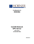
User Manual for the IC320CGM510 IC320CGM560 IC320CGM562 CsCAN Network OPC Server Fourth Edition March 06, 2002 GFK-1635C PREFACE 06 MAR 2002 PAGE 3 GFK-1635C Warnings, Cautions, and Notes as Used in this Publication Warning Warning notices are used in this publication to emphasize that hazardous voltages, currents, temperatures or other conditions that could cause personal injury exist in this equipment or may be associated with its use. In situations where inattention could cause either personal injury or damage to equipment, a Warning notice is used. Caution Caution notices are used where equipment might be damaged if care is not taken. Note Notes merely call attention to information that is especially significant to understanding and operating the equipment. This document is based on information available at the time of its publication. While efforts have been made to be accurate, the information contained herein does not purport to cover all details or variations in hardware or software, nor to provide for every possible contingency in connection with installation, operation, or maintenance. Features may be described herein which are not present in all hardware and software systems. GE Fanuc Automation assumes no obligation of notice to holders of this document with respect to changes subsequently made. GE Fanuc Automation makes no representations or warranty, expressed, implied, or statutory with respect to, and assumes no responsibility for the accuracy, completeness, sufficiency, or usefulness of the information contained herein. No warranties of merchantability or fitness for purpose shall apply. The following are trademarks of GE Fanuc Automation North America, Inc. Alarm Master CIMPLICITY CIMPLICITY 90 – ADS CIMPLICITY Power TRAC CIMSTAR GEnet Genius Genius PowerTRAC The following are trademarks of Horner APG, LLC. Cscape SmartStack Helpmate Logicmaster ModelMaster ProLoop PROMACRO Series One Series Three Series Five CsCAN The following are trademarks of the Open DeviceNet Vendor Association (OVDA), Inc. DeviceNet Copyright 2002 GE Fanuc Automation North America, Inc. All Rights Reserved Series Six Series 90 VuMaster Workmaster PAGE 4 GFK-1635C 06 MAR 2002 PREFACE PREFACE 06 MAR 2002 PAGE 5 GFK-1635C Revisions to This Manual This version (GFK-1635C) of the CsCAN Network OPC Server User Manual contains the following revisions, additions, and deletions: 1. Reorganized and revised Chapter 1. Deleted Section 1.3, Section 1.4, and Section 1.6; renumbered remaining sections. 2. Moved Software Installation from Chapter 3 to Chapter 2. Reorganized and revised Chapter 2. 3. Moved OPC Server Operation from Chapter 4 to Chapter 3. Reorganized and revised Chapter 3. Added OPC Menu information. Moved Section 3.5: Setting CGM500 Parameters to Chapter 6. 4. Renamed Chapter 4 to Data Access. Reorganized and revised Chapter 4. Moved Section 4.8 to Network Status (Section 3.4.4, Item a). Moved Section 4.5.1 to Chapter 5: Starting the Device Driver. Moved Section 4.9:Troubleshooting to Chapter 8. 5. Added new Chapter 5: Starting the Device Driver. 6. Added new Chapter 6: CGM500 Configuration. 7. Added new Chapter 7: CGM560 Configuration. 8. Added new Chapter 8: Troubleshooting. 9. Moved Programming Examples from Appendix C to Appendix A. 10. Replaced and renamed Appendix B to DCOM Configuration. 11. Added a new Appendix C: Custom Interface. PAGE 6 GFK-1635C 06 MAR 2002 PREFACE PREFACE 06 MAR 2002 PAGE 7 GFK-1635C Table of Contents CHAPTER 1: INTRODUCTION...............................................................................................................9 1.1 General..................................................................................................................................... 9 1.2 Terminology .............................................................................................................................. 9 1.3 CsCAN Network OPC Server - Functionality Overview .............................................................10 1.4 Limitations................................................................................................................................10 CHAPTER 2: SOFTWARE INSTALLATION .........................................................................................11 2.1 Installation................................................................................................................................11 CHAPTER 3: OPC SERVER OPERATION...........................................................................................13 3.1 General....................................................................................................................................13 3.2 Network Tree ...........................................................................................................................13 3.3 Tag List....................................................................................................................................13 3.4 Menu System...........................................................................................................................13 3.4.1 File................................................................................................................................... 13 3.4.2 Tags ................................................................................................................................ 14 3.4.3 Config .............................................................................................................................. 15 3.4.4 View................................................................................................................................. 16 3.4.5 Help ................................................................................................................................. 18 CHAPTER 4: DATA ACCESS ..............................................................................................................19 4.1 General....................................................................................................................................19 4.2 Components of a Name Space.................................................................................................19 4.3 Accessing Global Registers and Internal Registers...................................................................19 4.3.1 Global Register and Internal Register Access Path........................................................... 19 4.3.2 Access path: NetX_NodeY ............................................................................................... 19 4.3.3 Global Registers............................................................................................................... 20 4.3.4 Internal Registers ............................................................................................................. 20 4.4 Accessing Diagnostic Items......................................................................................................22 4.4.1 Access Path for Diagnostic Items ..................................................................................... 22 4.4.2 Network Status Item Name Syntax ................................................................................... 23 4.4.3 Message Log Status Item Name Syntax ........................................................................... 23 4.5 Accessing Items Without Using Access Path ............................................................................23 4.6 Supported Data Types .............................................................................................................24 CHAPTER 5: STARTING THE DEVICE DRIVER...................................................................................25 5.1 Windows NT ............................................................................................................................25 CHAPTER 6: CGM500 CONFIGURATION ............................................................................................27 6.1 Start the CsDrvParam Program................................................................................................27 6.2 Set the Segment Addresses for the Boards Used .....................................................................27 6.3 Select the Parameters for all CsCAN Networks ........................................................................28 CHAPTER 7: CGM560 CONFIGURATION ............................................................................................31 7.1 Start the Program.....................................................................................................................31 7.2 Configure the Card...................................................................................................................31 CHAPTER 8: TROUBLESHOOTING .....................................................................................................33 8.1 Initial TroubleShooting Procedures...........................................................................................33 8.2 Troubleshooting Faults / Solutions............................................................................................33 APPENDIX A: PROGRAMMING EXAMPLES .......................................................................................37 1 Visual Basic.................................................................................................................................37 1.1 Reading Values....................................................................................................................... 37 1.2 Writing Values......................................................................................................................... 39 1.3 Writing Global Values Simultaneously ..................................................................................... 41 2 Excel ...........................................................................................................................................43 2.1 Reading Values....................................................................................................................... 43 3 CIMPLICITY HMI.........................................................................................................................43 4 RSView32 ...................................................................................................................................45 PAGE 8 GFK-1635C 06 MAR 2002 PREFACE APPENDIX B: DCOM CONFIGURATION..............................................................................................49 1 The GUEST account....................................................................................................................49 2 Configure the DCOM Client .........................................................................................................49 3 Configure the DCOM Server ........................................................................................................50 4 Accessing Remote DCOM points.................................................................................................51 APPENDIX C: CUSTOM INTERFACE...................................................................................................53 INDEX ...................................................................................................................................................55 CH. 1 06 MAR 2002 PAGE 9 GFK-1635C CHAPTER 1: INTRODUCTION 1.1 General The CsCAN OPC Server (IC320CGM510) is an OPC (OLE for process control) compliant server for accessing a CsCAN network. The server runs under the Microsoft Windows 95, Windows 98, WindowsNT, and Windows 2000 operating systems with approximately 5 megabytes of free hard disk space. A variety of communication device options are available for interfacing with the CsCAN network. The OPC Server supports from one to ten CsCAN networks depending on the selected communication option. When using the computer serial port as the communication device, only 1 network is supported. When using five CGM502s or five CGM562, up to ten CsCAN networks are supported. Only the OPC Custom Interface (Data Access Standard 1.0A – Appendix C of this manual lists the interfaces/methods provided by the server) is supported. C++ Programmers can write programs using the Custom Interface. Programmers using scripting languages (e.g., Visual Basic or Excel) can access the Server using DDE (Dynamic Data Exchange) syntax or OPC compliant ActiveX controls. OPC is based on the Microsoft COM (Common Object Model) specifications. COM introduces a great deal of hardware and software independence. OPC runs on any hardware platform using any language that supports COM. Any hardware dependent code is limited to hardware-specific Device Driver modules supplied by the manufacturer of the hardware. The ISA CsCAN Interface Board (HE200CGM500 or HE200CGM502) provides the necessary interface with the CsCAN network. The CGM500 is a single-channel gateway, and the CGM502 is a dual-channel gateway. CGM500 is used hence forth in this manual to refer to either CGM500 or CGM502. The PCI CsCAN Interface Board (IC320CGM560 or IC320CGM562) provides the necessary interface with the CsCAN network. The CGM560 is a single-channel gateway, and the CGM562 is a dual-channel gateway. CGM560 is used hence forth in this manual to refer to either CGM560 or CGM562. 1.2 Terminology A DATA SOURCE is a piece of hardware or software that provides or accepts data to or from an application program. Typically, this is a hardware device (i.e., CGM500 / CGM560), but it could also be a software package such as a database or spreadsheet. The DEVICE DRIVER is the code provided by the hardware manufacturer and is responsible for handling the hardware peculiarities of hardware such as the CGM500 / CGM560 card. The SERVER is the program, which takes the data from the Device Driver and passes it to a Client program. The Server must adhere to OPC specifications such that any OPC compliant Client can request data from any OPC compliant Server. The CLIENT is the user-side program that requires data from the CsCAN network. This program can be written in C++ or in a scripting language (i.e., Visual Basic or Excel). The INTERFACE is the user-written code that transfers information back and forth between the Server and the Client. This can be as simple as an external cell reference in Excel or as complex as a custom written C++ program. PAGE 10 GFK-1635C 1.3 06 MAR 2002 CH.1 CsCAN Network OPC Server - Functionality Overview CsCAN is the name given to Horner APG’s proprietary network protocol. This protocol is used primarily with Operator Control Station (e.g., OCS1xx / OCS2xx) or Remote Control Station products (RCS210). CsCAN is based on Controller Area network (CAN) Bus technology from Robert Bosch. The CsCAN protocol supports Global Registers and Internal Registers (such as %R, %SR etc.). Global Registers are transmitted around the network without a need for a Master Controller or Scanner. Internal Registers are not transmitted around the network automatically and need to be explicitly scanned. The OPC Server is normally used as a monitor to listen to the Global Registers of other nodes on the network. It can, however, be configured as a node on the network and can write it's own Global Network Data Points (which can then be read by other nodes on the network). 1.4 Limitations The CsCAN OPC Server operates under Windows-95 or Windows-98 when using the serial port as the means of communication. However, DCOM for Windows-95 or Windows-98 does not support the CsCAN OPC Server. The remote CsCAN OPC Server must be run under Windows-NT or Windows-2000 when using DCOM. The client can run under Windows-95 or Windows-98. CH. 2 06 MAR 2002 PAGE 11 GFK-1635C CHAPTER 2: SOFTWARE INSTALLATION 2.1 Installation The Windows operating system must be installed and operating on the host computer. Do not attempt to install Device Drivers or OPC Severs until the Windows operating system is completely functional. 1. Boot the computer into the ADMINISTRATOR mode to ensure proper installation of the Device Driver. 2. Insert Distribution Diskette #1 into the floppy disk drive or Insert the Distribution CD into the CD ROM drive. 3. Open a directory window to the floppy disk drive or CD ROM drive, then double-click the SETUP.EXE program. Follow the instructions presented by the Setup Wizard to complete the installation. The critical step is specifying the home directory for the file. The default directory can be used if it suits the needs of the system. The installation process also makes all necessary changes to the system registry and provides information for the Uninstall feature from Window's Control Panel. PAGE 12 GFK-1635C 06 MAR 2002 NOTES CH. 2 CH. 3 06 MAR 2002 PAGE 13 GFK-1635C CHAPTER 3: OPC SERVER OPERATION 3.1 General The server interface consists of three main elements; A Menu System for configuring, diagnosing and viewing connection information, a Network Tree for configuring and viewing nodes and tags for each network, and a Tag List for viewing and editing tags for a given node. The following sections describe the overall server operation. Menu System Tag List Network Tree Figure 3.1 – Main Screen 3.2 Network Tree The Network Tree is used for configuring nodes on a network and also shows a graphical representation of how the CsCAN network is arranged. All 10 networks are displayed as well as a Diagnostic branch. When the communication method is set to use the serial port, only the first network can be used. 3.3 Tag List The Tag List displays the configured tag information for a selected node on a network. It is also used to modify a selected tag. 3.4 Menu System The main Menu System consists of File, Tags, Config, View and Help. 3.4.1 File The file menu is used to control the configuration file. It contains the standard items that are found in many windows programs; New, Open, Save, Save As. PAGE 14 GFK-1635C 3.4.2 06 MAR 2002 CH. 3 Tags OPC clients can connect to the server and gather data two different ways. One way is for the client to browse pre-configured tags in the server and use the tags to access the data. The other way is for the client to directly access the data, which is described in the Data Access section. The Tags Menu is used in conjunction with the network tree to modify nodes and tags for a given network so an OPC client can browse and connect to the tags. Right-clicking on the Network Tree also display the Tags Menu. a. Add Node A node must first be added to a given network in order to add tags. A node represents a single OCS/RCS unit. • Click on the desired network in the network tree • Click Add Node • Enter the node number and node name • Select OK b. Add Tag Tags can be added to nodes on any network. A tag represents a data point from a given node. There are 2 types of data points, Global Register and Internal Register. They are described in more detail in the Data Access section. Both types of data points can be used when configuring the tag information. • • • • • • • • • • c. Click on the desired node in the network tree Click Add Tag Select the type of register access the data point will use (Global or Internal) Select the type of register Select the offset Select the Bit Length (If Internal register is select) Select the Bit Offset (If Internal register is select) Enter the Tag name Enter a optional comment Select OK Edit Edit changes operation depending if a network, node or tag is selected. If a network is selected in the Network Tree and Edit is clicked then the network name can be modified. If a node is selected in the Network Tree and Edit is clicked then the node number and node name can be modified (See Add Node). If a tag is selected in the Tag List and Edit is clicked, then the tag information can be modified (See Add Tag). CH. 3 3.4.3 06 MAR 2002 PAGE 15 GFK-1635C Config The Config menu is used to configure elements of the server’s operation. a. Scan Setup The scan setup is used to configure the communication method for accessing the CsCAN network, the rate at which the global and internal registers are scanned, and the number of successive node errors before a node is taken off-line. Communication Method There are various options for communicating with the CsCAN network. The two general methods are to use the serial port and communicate through an OCS or RCS or use a network card in the PC and communicate through a driver. Depending on the communication method, further device configuration can be necessary. The Device Setup button displays a different configuration window depending on the communication method selected. See Chapter 6 for CGM500/CGM502 and Chapter 7 for CGM560/CGM562 configuration. Scan Rate There are two options for selecting the type of scan rate; as fast as possible or fixed. If the Fixed Scan Rate box is not selected, then the server scans the nodes as fast as possible. If the box is selected, then a Global Data Scan Rate and Internal Register Scan Rate must be entered. The Global Data Scan Rate is the rate at which the server requests global data from the network and checks for internal register updates. The Internal Register Scan Rate defines the rate the server requests internal register data. Scan Retries The Scan Retries value defines the number of successive scan errors before a node is taken off-line. This prevents the network from experiencing continual update delays due to a node or nodes not communicating with the server. b. Log Setup The server contains an event log. The Log Setup allows for configuring how the event log operates. The event log can be saved to a file by clicking the Log to File check box. When selected, the option for clearing the log on startup and selecting a log file is enabled. The Max Entries value defines the number of entries in the log file before the log file wraps around and overwrites the existing entries. c. Startup Setting The Startup Setting is used to define a configuration file that the server loads at startup. If the client application is expecting specific tags to be available in the server then the default file needs to be set. d. Connect Via Modem The server has the ability to connect via a modem. The modem connection only works if the Communication Method is set for a serial connection. Connect Via Modem is used to configure the modem connection information. Once the modem settings are configured, the CONNECT button is clicked in order to make the actual connection. The HANG UP button is used to disconnect. PAGE 16 GFK-1635C e. 06 MAR 2002 CH. 3 Start Server After the server is launched, the server attempts to start automatically. When using a network card to communicate with the network, the device driver MUST be started before the server is launched. (See Chapter 5: Starting the Device Driver.) An error occurs if the device driver is not available when the server attempts to start, and the server stops. There are two primary ways to launch the server: -Double-click the CSOPCSRV.EXE or a shortcut to CSOPCSRV.EXE -Configure a client to attach to the server when the client starts. The Start Server menu item is used to start the server after it has stopped. The icon with the green light can also be used. f. Stop Server Closing the server, clicking on the Stop Server menu item, and clicking on the icon with the red light all causes the server to stop. Links to the server items in OPC clients may need to be closed before stopping the server. A warning is displayed if the server attempts to stop with clients connected. Do NOT stop the device driver while the server is running. If you attempt to stop the device driver before you close the server, the device manager does not necessarily allow you to stop the driver. 3.4.4 View The view menu is used to view elements of the server’s operation. a. Network Status The Network Status menu item displays the network status of all configured networks. This is helpful in diagnosing potential network problems. Possible Status Messages: OK: On-Line (OCS Node) • Network is online and operating normally as the OCS node ID. OK: On-Line (Full Control) • Network is online and operating normally in Full Control mode OK: On-Line (Monitor Only) • Network is online and operating normally in Monitor Only mode (node ID 255) Not used: Off-Line • Network is not currently configured Error CGM500: Segment Addr • Board address in CsDrvParam program does not match the address set by the dip switches on the CGM board Error CGM500: Msg Overrun • Incoming Global data from network nodes is updating too fast for the computer processor to keep up with CH. 3 06 MAR 2002 PAGE 17 GFK-1635C Error CGM500: Firmware ver • The firmware is not responding to the device driver (not compatible versions of firmware & device driver) Error CGM500: RAM check • The CGM500 RAM check at start-up failed Error CGM500: Timeout • CGM500 timed out when communicating with the network Error CGM500: Write Timeout • CGM500 timed out when attempting to Write data to the network (the network may be too busy and with the present node priority of CGM500, it is not getting the time slot to send its messages to the network) Error CGM500: General • Error experienced by device driver when trying to ‘talk’ to the CGM500 Net Err: Duplicate ID • Network node ID is in conflict with another network node, cannot have two nodes with same ID b. Activity Log The Activity Log provides a means to see the activity taking place inside the server. The activities are time-stamped (resolution in seconds). When a maximum number of messages are logged as specified in the Log Setup, the older entries are overwritten. Listed below are the types of activities, which are logged: • • • • • • • Connection requests for a network node Connection requests for data items Data item taken off-line Data item that was off-line is back on-line Write requests for Internal Register data items Write complete messages for Internal Register data items Scan missed and scan error messages for Internal Register data items The Activity Log dialog also lists the data items that are taken off-line by the server upon successive scan errors. These points can be brought back on-line either by using the button provided on the dialog or by using the Diagnostic data item MsgLog_Status as described in Chapter 4: Data Access. PAGE 18 GFK-1635C c. 06 MAR 2002 CH. 3 Scan Groups A single request for mulitple registers is processed faster than individual requests for the same registers. Instead of making a series of individual register requests to a single node, the server can request a consecutive block of registers. The server attempts to maximize CsCAN communication by analyzing the configured Internal Registers and grouping them together so it can request a block of registers instead of making individual requests. The groups can be viewed using the Scan Groups menu item. NOTE: Consecutive registers need to be used in order to maximize communications. 3.4.5 Help The help menu contains a menu item that displays the online help. It also contains a menu item that displays the About box. CH. 4 06 MAR 2002 PAGE 19 GFK-1635C CHAPTER 4: DATA ACCESS 4.1 General The CsCAN Network OPC server provides a means for OPC clients to access the following data: • • • • Global Registers (Data Points) of CsCAN network nodes Internal Registers of CsCAN network nodes Diagnostic items within the OPC server. Global Data Array Write ) of CsCAN network nodes The means by which an OPC Client accesses the above data items is through an OPC Server’s name space. 4.2 Components of a Name Space An OPC Client can talk to multiple OPC Servers at the same time. However, in order to do so, the OPC Client must have a way to uniquely identify which OPC Server it wishes to talk to as well as which device and data item it is interested in. This combination of information is called the name space of a particular OPC Server. The name space of an OPC Server consists of the following three components: 1. OPC Server Application ID – This is basically a means for an OPC client to identify a particular OPC server. The Application ID for CsCAN OPC Server (Version 3.10 and above) is: CsCAN. Note: Users upgrading from earlier versions of the OPC Server need to change to the application ID to CsCAN. 2. Access Path – This is the device address where the related data item can be found. 3. Item Name – This describes the item (point) the OPC client is interested in. Note: The way an item name and its access path are specified can vary from one OPC Client to another, but this information needs to be provided to the OPC Server to uniquely identify a data point. Some OPC Clients do not have a provision to specify Access Path. 4.3 Accessing Global Registers and Internal Registers Global and Internal registers share the same type of nomenclature used to access the OPC Server data. Both use an access path and an item name. The access path is the same. The item names are different. 4.3.1 Global Register and Internal Register Access Path 4.3.2 Access path: NetX_NodeY X is the network number (1 - 10) and Y is the node number (1 - 253) where the required data is present. “Net” and “_Node” are required letters in this access path syntax. Example: Net1_Node5 means the required data is available on Node 5 of Network 1. PAGE 20 GFK-1635C 4.3.3 06 MAR 2002 CH. 4 Global Registers Currently, a CsCAN network node can have up to 64 bits of Global Digital Data and 32 words of Global Analog Data. An OPC Client can access all of the Global Network Data Points from every node on the network(s) through the OPC Server. The OPC Client can also write Global Network Data Points to the network if the OPC Server has a valid Node ID (1 through 253). Global Digital Data Points are numbered from 1 to 64, inclusive. Global Analog data Points are numbered 1 to 32 inclusive. In order to access a single data point, the Client program must make a request to the Server, giving the Network number, Node ID, Data Type, and Offset of the desired data point. For example, the client might request Network 1, Node ID 4, Global Analog Data Point 6. Note: Global Analog Data is 16-bit only; 32-bit is not supported. Global Register Item Name Syntax Item Name syntax for Global Register: Tz where T is the letter ‘A’ for Analog or ‘D’ for Digital and z is the point number (1-16 for Analog and 1 - 64 for Digital). Example: A12 is the item name to access Analog Point 12 (%AQG12) of device specified by the access path 4.3.4 Internal Registers The Internal Registers are not transmitted automatically around the network as is Global Data. So, these need to be explicitly scanned. The server sends a request to the corresponding CsCAN node over the network for the Internal Register, and then, the node sends the requested data. Every Scan Period, the OPC server checks if a scan is due for an internal register. It is important to note that only one Internal Register scan per network can be initiated every Scan Period (provided that the earlier scan is complete). As a result, an internal register might not be scanned at the exact internal register rate. It depends upon Scan Period, network traffic and the register scan rate. Note that Global Output Registers (AQG/QG) can be accessed as Internal Registers. These are also, in fact, transmitted as Global Data Points and thus ought not be accessed by the OPC clients as Internal Registers as far as possible, because that might unnecessarily affect the scan times of other Internal Registers. CH. 4 06 MAR 2002 PAGE 21 GFK-1635C Accessing of following Internal Registers is supported at this time: Table 4.1 – Internal Registers Register Name Default Length (‘RegName’ to use in Access Type (in bits) item name) AI 16 Read/Write AQ 16 Read/Write AIG 16 Read/Write AQG 16 Read/Write R 16 Read/Write I 1 Read/Write IG 1 Read/Write Q 1 Read/Write QG 1 Read/Write M 1 Read/Write T 1 Read/Write Read Only SR 16 Read Only K 1 Read Only S 1 Internal Register Item Name Syntax Item Name syntax for Internal Registers: [%]RegNameA[.B][,REAL] where terms in [ ] are optional and may be needed depending upon the type of access desired. “%” is an optional prefix and is provided for compatibility with Cscape. “RegName” is replaced with the desired register name in Table 4.1 “A” is the register address. Valid addresses depend on the controller used; refer to the controller manual for supported controller addresses. “B” is the bit offset (1 - 16) within the register. The default bit offset is 1. ‘.’ preceding the bit offset is a required character when specifying bit offset. “L” is the ‘desired length’ (1, 8, 16 or 32) of the register in bits. The default length is as specified in Table *.* for the specified Register Type. Note that the desired length can be different than the default length specified in the table. ‘_’ preceding the length is a required character when specifying register length. If a length other than ‘1’ is used, the bit offset needs to be either 1 (the default) or 8. PAGE 22 GFK-1635C 06 MAR 2002 CH. 4 “REAL” specifies the register as a Real or Floating Point value and is to be used in conjunction with the “L” switch as it requires a 32-bit register. ‘,’ preceding this switch is a required character when specifying a Real value. Examples: R10 Register %R10 (with bit offset of 1 and length of 16 bits) is scanned with low priority and with the default scan rate for the node specified with Access Path. %R25.2 Bit 2 of %R25 is scanned with the default scan rate. Note that the ‘%’ preceding R25.2 is optional and can be omitted. AQ25_32,REAL Internal Registers %AQ25 and %AQ26 can be written to as a single 32-bit register containing a Real number. 4.4 Accessing Diagnostic Items There are two supported diagnostic items that clients can access; network status and message log status. Like the register access, they require an access path and item name. 4.4.1 Access Path for Diagnostic Items The following is the access path to access the diagnostic items supported by the server. Access Path: DIAG CH. 4 4.4.2 06 MAR 2002 PAGE 23 GFK-1635C Network Status Item Name Syntax Item name syntax for network status: NetX_Status Where X is the network number (1 – 10). These items are WORD type (16-bit), Read-Only and serve to access the status of every network from within an OPC client. The status of networks’ can also be viewed from the OPC server using the ‘view’ menu. Following are the status code values provided by this item. Value 0 1 Table 4.2 – Network Status Codes Status Not Active (Off-Line) – Network is not currently configured Status OK – OPC Server program is operating normally and no problems encountered communicating with the CGM500 gateway for this network Other than 0 or 1 4.4.3 Error – Check the OPC server status from its view menu Message Log Status Item Name Syntax Item name syntax for message log status: MsgLog_Status This is a WORD type (16-bit) Read/Write data item. It provides a means from within an OPC client to get the status of the OPC server’s massage log. The item is bit-coded; the item bits are interpreted as follows: Bit Number 1 (LSB) 2 3 4 5 4.5 Table 4.3 – Message Log Status Codes Meaning if, upon reading the data Action taken if, when writing to the item, the bit is set data item, the bit is set One or more messages in the log Clears all messages in the log One or more Low Priority Internal Resets this bit if it is set Register items missed a scan when one was due One or more High Priority Internal Resets this bit if it is set Register items missed a scan when one was due Some points were taken off-line Brings the points that were taken offbecause of successive errors line due to scan errors back on-line scanning the item Write error when writing to an Resets this bit if it is set Internal Register data item Accessing Items Without Using Access Path For OPC Clients that do not support item access using an Access-Path, the following alternate form is suggested: [Access Path]Item Name In this syntax, the access path is embedded into the item name, so the access path need not be specified separately. PAGE 24 GFK-1635C 4.6 06 MAR 2002 CH. 4 Supported Data Types Some clients (such as Cimplicity HMI) need to specify the item type explicitly (DINT, BOOL etc.) when specifying the item (item name, access path etc.) The bit-type items supported in the OPC Server name space can be accessed as BOOL items (boolean, i.e. True or False). NOTE: It is important to note that the word-type items supported in the CsCAN Network OPC Server name space must be accessed as either DINT (32-bit signed integer) or UDINT (32-bit unsigned integer). Thus the analog and diagnostic data items must be accessed as either DINT or UDINT, even though these are 16-bit values. CH. 5 06 MAR 2002 PAGE 25 GFK-1635C CHAPTER 5: STARTING THE DEVICE DRIVER Before attempting OPC Server communications using a network card, the associated Device Driver must be started. 5.1 Windows NT To start one of the Device Drivers, first open the Device Manager which appears in the Windows Control Panel. It is reached through the START Button. Select the Device Driver and then click the START button. The driver starts and eventually indicates that it is running. • CGM500/CGM502 uses CsCANDrv When the driver first starts, it scans the network in order to make sure that the CGM500 Node ID does not conflict with any other node on the network. The driver responds within 15–45 seconds. • CGM560/CGM562 uses i331 Select Startup to change the startup mode of the driver. If it is known that the OPC Server is always operational, the driver can be set to automatic. Click here to start the driver. Click here to change the Startup Mode. Figure 5.1 – Devices Screen 5.2 Windows 2000 The method used to access device drivers changed in Windows 2000. 1. 2. 3. 4. 5. 6. 7. Use the following procedure: Right click on My Computer to display System Properties Click on the Hardware tab Click on Device Manager to display the Device Manager window Click View on the Device Manager menu and select Show hidden devices Non-Plug and Play Drivers will be added to the device tree Double click Non-Plug and Play Drivers to expand the driver list Double click the driver name to display the Properties window • CGM500/CGM502 uses CsCANDrv • CGM560/CGM562 uses i331 PAGE 26 GFK-1635C 8. 9. 06 MAR 2002 CH. 5 Click the Driver tab in the Properties window • Click Start to start the Device Driver When the CsCANDrv driver first starts; it scans the network in order to make sure that the CGM500 Node ID does not conflict with any other node on the network. The driver responds within 15–45 seconds. • Click Stop to stop the Device Driver • Set the Startup Type by using the drop-down menu. If it is known that the OPC Server is always operational, the driver can be set to automatic. Click OK to keep the settings. Figure 5.2 – Devices Screen CH. 6 06 MAR 2002 PAGE 27 GFK-1635C CHAPTER 6: CGM500 CONFIGURATION Note: The following configuration example uses a CGM500 for the communication method. The CsDrvParam.EXE program is used to set the CGM500 card’s driver (CsCANDrv) parameters. The installation program puts CsDrvParam.EXE in the installation directory. This section explains how to use the CsDrvParam.EXE program. 6.1 Start the CsDrvParam Program One way to start CsCrvParam is to use the Config/Scan Setup menu option. If the the communication method is set to CGM500; then click the Device Setup button. Another option is to double-click the CsDrvParam.EXE program file. The CsDrvParam program starts with the following dialog screen. Figure 6.1 – Driver Properties 6.2 Set the Segment Addresses for the Boards Used By default the segment address of Board# 1 is 0xd000. It is recommended to use the default setting unless the user experiences address conflict with the existing hardware in the computer. Also, by default, the segment addresses for the rest of the boards (Board# 2 through 5) are not assigned (N/A). If more than one CGM500 board is used, set the segment address for those boards also. These need to match the segment addresses selected on the CGM500 board using DIP switch settings (Refer to the Hardware Installation section to see how the DIP switch on a CGM500 is set). Do not use same segment address for multiple boards. The SET button must be pressed each time the address is changed and before another board is configured. Click here to set the Segment Address. Figure 6.2 – Segment Address PAGE 28 GFK-1635C 6.3 06 MAR 2002 CH. 6 Select the Parameters for all CsCAN Networks After setting the segment addresses for the boards used, select the parameters for the networks with which the OPC Server needs to communicate. By default, only Network# 1 is ‘Active’. This means that the device driver gathers the global data from this network and makes it available to the OPC Server. It is able to write the data requested by the OPC Server to the network. By default, the Networks 2 through 10 are not active and are not able to communicate with the OPC Server. If more than one network must be used, make the corresponding network active by checking the Active box for that network. Check here to make the network active. Figure 6.3 - Active Network Active Networks Select the CGM500 Board Number (1 through 5) and the Gateway (A or B) on that board to use. No two active networks can use the same Gateway of the same board. Select the CGM500 board number to use. Select the CGM500’s gateway. Figure 6.4 - Gateway Select the Access Type (OCS Node or Full Control) and Node ID (1 through 253). A CGM500 Gateway can be configured as either a Regular OCS node or as a Full Control OCS node. In either mode, CGM500 Gateway reads all Global Data on the network. The difference in the two modes is in the amount of data CGM500 is able to write to the network. Presently, a CsCAN network node can have up to 16 words and 64 bits of Global Data. As a Regular OCS Node (which usually is the case), the CGM500 Gateway is assigned a network node ID (1 through 253). So, it is capable of broadcasting one node equivalent of Global Data on the network. Note: As a Regular OCS Node, CGM500 Gateway can also be assigned a node ID of 255 to configure the Gateway only to read the global data on the network. In this case, the Gateway is not able to broadcast any global data to the network. If the Gateway is configured as a Full Control OCS Node, it is still assigned a node ID when setting the driver parameters. When scanning internal registers, the Gateway needs to assume a node ID, and it is the node ID specified here that is assumed in those cases. This node ID must be one that is not used by any other device on the network. However, the OPC Server can dynamically assign the Gateway a different node ID when broadcasting global data on the network. This way, the Gateway can be assigned multiple unused IDs on the network, thereby increasing the amount of global data that can be broadcast to the network several times. CH. 6 06 MAR 2002 PAGE 29 GFK-1635C Note: If the node ID is already assigned to a network node and is also assigned to the Gateway and is used to broadcast global data on the network, the other network node (with the same ID) stops network communications. So, the Full Control mode needs to be used with caution when broadcasting data on the network. Select the CGM500 gateway’s network access mode. Select the CGM500 gateway’s network ID. Figure 6.5 - OCS Node and Full Control After changing any of the above parameters for a network, click Apply button for the change to take effect. If the Apply button is not clicked, the changes are discarded. After selecting the network’s parameters, click here for the network parameters to take effect. Figure 6.6 – Parameters Take Effect After selecting parameters for all networks, click ‘OK’ button to accept the changes and click ‘Cancel’ button to discard the changes. When OK is clicked, the changes are copied to the registry, and the driver must be restarted for the changes to take effect. PAGE 30 GFK-1635C 06 MAR 2002 NOTES CH. 6 CH. 7 06 MAR 2002 PAGE 31 GFK-1635C CHAPTER 7: CGM560 CONFIGURATION Note: The following configuration example uses a CGM560 (PCI/331) for the communication method. This section explains how to use the CGM560 configuration program (PCI/331). The communication method must be set to ESD Card for the OPC Server to use the CGM560. 7.1 Start the Program If the communication method is set to ESD Card then the Device Setup button on the Scan Setup window will not display the configuration program. There are two options for starting the configuration program. One option is to use the Windows Start/Programs/Can/PCI 331 Configuration Tool. The second option is to go to Windows Start/Settings/Control Panel and double click on CAN Control. The program starts with the following dialog screen. Figure 7.1 – CAN Control Panel 7.2 • • • Configure the Card Click on the PCI/331 tab. In the Interface section, click the radio button next to the interface number to be configured. In the Base Net section, set the base network number assigned to the CAN module. If a module has more than one physical CAN interface, the first interface is associated with the logical network number specified in Base Net, and the following are counted up from there. Attention: Make sure that no number is assigned twice when logical network numbers are assigned! PAGE 32 GFK-1635C 06 MAR 2002 NOTES CH. 7 CH. 8 06 MAR 2002 PAGE 33 GFK-1635C CHAPTER 8: TROUBLESHOOTING This section discusses various problems one can encounter when using the OPC Server and the possible solutions. 8.1 Initial TroubleShooting Procedures In case of any problem, first make sure of the following: 1. The installation was carried out in Administrator mode if using Windows-NT or Windows2000. 2. CsCAN OPC server as well as some other OPC servers/clients use IC32CKIT DLL. There needs to be only a single copy of this DLL file and needs to be located in the System32 folder of Windows NT. If you have more than one copy of IC32CKIT.DLL file on the computer, delete all the old versions and place the newest in the System32 folder. Also CsCAN OPC server needs at least version 2.0.72 of this file. You can find the version of the file by right clicking on the file and selection Properties. If you do not have at least Version 2.0.72 of this file, contact technical support for an update. 8.2 Troubleshooting Faults / Solutions Problem# 1: If the CsCANDrv device driver does not appear in the Devices list when attempting to start the device driver, most probably the installation program was unable to make the necessary changes in the registry. This can happen if the installation of the OPC Server was carried out with a ‘nonAdministrator’ log-in mode for Windows-NT. No entry for CsCANDrv in the devices list Figure 8.1 – No Entry CsCANry Solution A: Make sure to log-in as Administrator in Windows-NT. Uninstall any previous installation of the OPC Server for CsCAN using ‘Add/Remove Programs’ applet in control panel. Reinstall the OPC Server using installation instructions in the manual. Solution B: If the installation was done according to the installation instructions, it might be necessary to restart the computer in order for the driver to appear in the Device list. PAGE 34 GFK-1635C 06 MAR 2002 CH. 8 Problem# 2: When attempting to start the OPC Server, the following message is displayed “The dynamic link library IC32CKIT.dll could not be found….”. This simply means that the IC32CKIT.DLL is not located when starting the OPC Server Solution: CsOPCSrv.EXE OPC Server program uses IC32CKIT.DLL internally. So, the program can not be started if the DLL can not be located. To solve the this problem, find the IC32CKIT.DLL file. (It is located in the installation directory chosen when installing the OPC Server.) Put it in the same directory where the OPC Server program is located or put it in the directory included in the system path. Problem# 3: Upon start-up, the OPC Server displays “Error CGM500: Segment Addr” as the network status for some CGM500 network gateway. The most probable cause for this error is (a) mismatch in the Segment Address for the CGM500 board set by DIP switch on the board and by the CsDrvParam Driver Parameters program; (b) The CGM500 board is not installed; or (c) The firmware revision in the CGM500 does not match the CsCANDrv driver revision. Segment Address mismatch Figure 8.2 – Segment Address Mismatch Solution: Ensure that the CGM500 board is installed as instructed in the ‘Hardware Installation’ section. Start the CsDrvParam program used to set the driver parameters. Make sure that the Segment Address for the board with network problem is the correctly set in the CsDrvParam program. Problem # 4: Upon start-up, the OPC Server displays “Net Err: Duplicate ID ”as the network status for some CGM500 network gateway. This means that a network node with the same node ID as that set for the CGM500 Gateway has been encountered. Duplicate Node ID found on the network Figure 8.3 – Duplicate Node ID Found Solution: Either change the node ID of the network node with the duplicate ID or change the node ID for the CGM500 Gateway. Refer to Chapter Six for details on how to change the CGM500 Gateway’s node ID. CH. 8 06 MAR 2002 PAGE 35 GFK-1635C Problem # 5: If for some reason the CGM500 board stops communication with the device driver, the following appears: “Error CGM500: Timeout” status for the corresponding network. This is usually caused when a warm start is performed (Windows NT is restarted) without stopping the CGM500 device driver. CGM500 board not responding Figure 8.4 – CGM500 Not Responding Solution A: Upon experiencing this error, you will need to close the OPC Server application and restart the device driver using the Devices applet in the control panel. If this does not help, try a cold start (turn-off the PC and then power-up). To avoid this problem in the first place when restarting the PC, first stop the CsCANDrv CGM500 device driver and then restart the PC. CAUTION: Never turn off power to the computer without first using the Shut Down option. Failure to do so can result in damage to the file structures on any disk drives and can result in permanent loss of critical data. Solution B: A beta version of the OPC software may be installed. In the case that dual network CGM boards (CGM502) are being used, the second port on each board may come up with the Timeout error, but only after the Driver has been stopped and restarted in the Control Panel. The only way to remedy this is to either completely power down the computer, restart it, and restart the driver, or obtain a released version of the OPC server. Problem # 6: When stopping the CsCANDrv Device Driver through the Control Panel, an error occurs; “Could not stop the CsCANDrv Service…The service is not responding to the control function.” Solution: The OPC Server software is still running. It must be closed before the driver is stopped. Problem #7: When starting CsOPCSrv.exe, the network status box shows the networks incorrectly, both in which networks were set up and what mode (OCS Node or Full Control) they were set for. Solution: Check the version of IC32CKIT.DLL file located in the System32 folder (within the Windows NT folder). CsCAN OPC server needs at least Version 2.0.72 of this DLL file. PAGE 36 GFK-1635C 06 MAR 2002 NOTES CH. 8 APPENDIX A 06 MAR 2002 PAGE 37 GFK-1635C APPENDIX A: PROGRAMMING EXAMPLES 1 Visual Basic Visual Basic is a common language used to access OPC Servers. The interface is easy to understand. Because the CsCAN OPC Server also supports DDE protocol, Visual Basic clients can access the items using DDE syntax. The DDE interface is discussed in many different texts on Visual Basic programming. This manual is not a tutorial on Visual Basic programming. It is assumed that the user is familiar with Windows-NT and Visual Basic. 1.1 Reading Values The following example creates a simple Percent Meter, which reads a raw input values from the OPC Server and then displays the value as a raw number, as a percent of maximum, and as a moving Bar Chart. Although very simple, the example demonstrates how to use OPC Server from Visual Basic and demonstrates some of the power available using Visual Basic. Note that the example was accomplished using only 11 lines of code. The example was created using Microsoft Visual Basic 4.0, 32-bit version. The completed form looks like this: Text1 Label1 Label2 Shape1 Figure 1 – Form 1 Use Visual Basic tools to create this form, and add the named objects on the screen. Use Visual Basic tools to view and edit the Form_Load() function: Private Sub Form_Load() 1 Text1.LinkMode = vbNone 2 Text1.LinkTopic = "CsCAN|net1_node1" 3 Text1.LinkItem = "A1" 4 Text1.LinkMode = vbLinkAutomatic End Sub This routine is executed when the form is loaded. The first line 1 makes sure that the link is closed. Setting LinkMode to vbNone closes any existing link. This needs to be done before changing the LinkItem or LinkTopic properties. PAGE 38 GFK-1635C 06 MAR 2002 APPENDIX A The second and third 2 3 lines set the topic and item respectively. These form the string that passes to the DDE Interface of the OPC Server. The fourth line 4 sets the Link Mode to AUTOMATIC. The value the Text1 object is updated automatically each time the requested value changes. Also, by setting this value to something other than vbNone (0), the link is initiated. Use the Visual Basic tools to view and edit the Text1_Change() function: Private Sub Text1_Change() 1 Static value, percent As Integer 2 Static percent_display As String 3 value = Text1.Text 4 percent = (value / 2400) * 100 5 percent_display = Str(percent) + "%" 6 Label2.Caption = percent_display 7 Shape1.Width = (value / 2400) * 1815 End Sub This routine is called any time the value in Text1 changes. Since the OPC link is set to vbLinkAutomatic, the value in Text1 is automatically updated each time the requested value changes. This causes the Text1_Change() routine to be called at the same time. The first two lines 1 2 declare some internal variables. Value defaults are integer values, but it is important that percent be declared as an integer as well. The third line 3 gets the value from the object. Remember, this was placed here by the OPC Server link in vbLinkAutomatic mode. The Text1.text value is automatically converted to integer format by Visual Basic. The fourth line 4 converts the reading into a percentage of full-scale value. The result is placed into an integer value (percent) in order to remove any fractional percentage readings. Full Scale is arbitrarily chosen to be “2400”. This value is defined by the application and sensors used. The fifth line 5 converts the integer percentage value into a string, and tacks on the percent sign. The 6 where it is automatically displayed. text is then placed into the Label2 object’s Caption property The seventh line 7 changes the size of the Bar Graph Shape1. The “1815” value is taken from the Shape1 properties when the object is created. This is the maximum length, or 100% of the object. This value, multiplied by percentage of full scale, is used to set the length of the Bar Graph, 0% to 100%. APPENDIX A 1.2 06 MAR 2002 PAGE 39 GFK-1635C Writing Values If it is necessary to write values through the network, the values must be written to the CGM500's global memory locations. The CGM500 writes these values to the network where they can be read by other nodes. It is possible to either write each value separately or to write any or all values simultaneously (array write). NOTE: The OPC Server can not write values directly to any other node’s non-global registers on the network. Refer to Chapter Six for details. The OPC Server must be properly configured for the Client to be able to write values to the CGM500 card during OCS Node mode and Full-Control mode. There are two requirements: The Node ID assigned to the OPC Server must not be 0 (zero), 254, or 255. The Node ID assigned to the OPC Server must be unique: that is, it must not be the same as any other node on the network. Visual Basic uses the LinkPoke method to write values to the OPC Server. First, configure the OPC Server to have a Node ID that fits within the previous restrictions. For this example, set the OPC Server Node ID to “253.” Add four Commands and three Text Boxes to the Percent Meter project: Command1 Text2 Text3 Command2 Text4 Command3 Command4 Figure 2 – Adding Commands PAGE 40 GFK-1635C 06 MAR 2002 Edit the Form_Load() routine, ADD the following code: Private Sub Form_Load() Text1.LinkMode = vbNone Text1.LinkTopic = "CsCAN|net1_node1" Text1.LinkItem = "A1" Text1.LinkMode = vbLinkAutomatic 'REM added code Text2.LinkMode = vbNone Text2.LinkTopic = "CsCAN|net1_node253" Text2.LinkItem = "A1" Text2.LinkMode = vbLinkManual Text3.LinkMode = vbNone Text3.LinkTopic = "CsCAN|net1_node253" Text3.LinkItem = "A2" Text3.LinkMode = vbLinkManual Text4.LinkMode = vbNone Text4.LinkTopic = "CsCAN|net1_node253" Text4.LinkItem = "A3" Text4.LinkMode = vbLinkManual End Sub Edit the Command1_Click() routine to read: Private Sub Command1_Click() Text2.LinkPoke End Sub Edit the Command2_Click() routine to read: Private Sub Command2_Click() Text3.LinkPoke End Sub Edit the Command3_Click() routine to read: Private Sub Command3_Click() Text4.LinkPoke End Sub And finally edit the Command4_Click() routine: Private Sub Command4_Click() Text2.Text = 0 Text2.LinkPoke Text3.Text = 0 Text3.LinkPoke Text4.Text = 0 Text4.LinkPoke End Sub APPENDIX A APPENDIX A 1.3 06 MAR 2002 PAGE 41 GFK-1635C Writing Global Values Simultaneously Version 2.00 and above of the OPC Server supports the use of an Array Write for Global values only. This method does NOT apply to internal registers. Using an Array Write, all specified global values are written to the network as an array. While writing global values separately works well when only one value at a time needs to be changed, it takes a fairly long amount of time to write all of the global values using something such as a For/Next loop. Assume approximately 100ms for each write, which includes the actual write time plus time to recover in order to make the next write. Multiplied by 16 Analog points, the total is 1.6 seconds to write the global Analogs, 6.4 seconds for the global Digitals. The Array Write takes approximately 10ms to write all 16 global Analog points AND all 64 global Digital points. This time includes only the amount of time it takes to write the values to the network since there is now no need to wait for another write. There are two requirements: The Node ID assigned to the OPC Server must not be 0 (zero), 254, or 255. The Node ID assigned to the OPC Server must be unique: that is, it must not be the same as any other node on the network. Modify the Write Values program from above to look like the following: Command1 Command2 and Command3 Removed Command4 Text5 (can be made ‘Not Visible’) Figure 3 – Adding Commands The textbox Text5 can be made invisible as it is only a holder for the array to be assembled. PAGE 42 GFK-1635C 06 MAR 2002 APPENDIX A Edit the Form_Load() routine and ADD the following code to what is already there: Text5.LinkMode = vbNone Text5.LinkTopic = “CsCAN|net1_node20” Text5.LinkItem = “da_write” Text5.LinkMode = vbLinkManual Edit the Command4_Click() routine to read: Private Sub Command4_Click() Text2.Text = 0 Text3.Text = 0 Text4.Text = 0 Text5.Text = "0" + Chr$(9) + "0" + Chr$(9) + "3" + Chr$(9) + "1" + Chr$(9) + Text2.Text + Chr$(9) + Text3.Text + Chr$(9) + Text4.Text Text5.LinkPoke End Sub Edit the Command1_Click() routine to read: Private Sub Command1_Click() Text5.Text = "0" + Chr$(9) + "0" + Chr$(9) + "3" + Chr$(9) + "1" + Chr$(9) + Text2.Text + Chr$(9) + Text3.Text + Chr$(9) + Text4.Text Text5.LinkPoke End Sub What the code for Command4 and Command1 does is build the array in the Text5 text box that will be written to the network. The different parts of the array are separated by an ASCII Tab character (Chr$(9)) and tacked together using the + symbols. The format for the array is as follows: st st Array = “Dig#” + Tab + “1 Dig” + Tab + “Alg#” + Tab + “1 Alg” + Tab + “Dig1” + Tab + “Dig2” + Tab + “Dig3” + Tab + “Dig4” + Tab + “Alg1” + Tab + “Alg2 +……+ “Alg15” + Tab + “Alg16” Where Array is the Array Text Box that is linked to the “da_write” LinkItem; Dig# is the number of Digital bits to write, from 0 to 64, Tab is the ASCII Tab Character, Chr$(9); st 1 Dig is the number of the first Digital bit to write, from 0 to 64; Alg# is the number of Analog Words to write, from 0 to 16; st 1 Alg is the number of the first Analog Word to write, from 0 to 16; Dig1, Dig2, Dig3, Dig4 are the Digital Words to write; Alg1, Alg2, ……, Alg15, Alg16 are the Analog Words to write; APPENDIX A 06 MAR 2002 PAGE 43 GFK-1635C The strings Dig1-Dig4 and Alg1-Alg15 are not ALL necessary if less than the maximum amount of global data is to be written. For instance, in the VB example, only 3 Analog values are being written, st st starting at the 1 Analog value. Note that Dig# and 1 Dig are both set to “0” since there are no Digital st values to be sent to the network. Also note that Alg# and 1 Alg are set to “3” and “1”, respectively, since there are only 3 Analog values to be sent to the network, starting with the first one. Since no Digital values are being sent, the Dig1-4 strings are left out and only the first three Analog strings, Alg1-3, are used. The 64 Digital values are grouped together into a total of 4 Words. When using the Array Write technique: Array = "4" + Chr$(9) + "3" + Chr$(9) + "0" + Chr$(9) + "0" + Chr$(9) + “15” rd 4 bits are being written starting with the 3 bit, and decimal 15 equals binary 1111. 2 Excel Excel can be used as an OPC Client, again using the DDE-style interface. 2.1 Reading Values To retrieve data from the OPC Serve and place it into a cell, first select the cell to be loaded and then enter the following OPC Access String into the associated formula: = CsCAN|Net1_Node1!’A1’ The equal sign, '=', is required. Otherwise this is the familiar Access String. 3 CIMPLICITY HMI GE Fanuc’s CIMPLICITY HMI supports OPC beginning with Version 4.0 (or higher). CIMPLICITY HMI versions earlier than 4.0 need to be upgraded. During the CIMPLICITY HMI install or upgrade, ensure that the OPC Client is selected in the Communications Options. NOTE: The complete OPC Client configuration is presented in great detail in CIMPLICITY HMI Owners’ Manual (GFK-1181). Please refer to that manual throughout the following discussion. 1. From CIMPLICITY HMI, create a New Project. Make sure that OPC Client is checked under PROTOCOLS. Use the CIMPLICITY Project Wizard to create Ports, Devices, and Points. 2. From the Project Wizard Step 1, select OPCCLIENT, and add Port OPC_0. This creates a port named MASTER_OPC_0. Under the General tab of the Port Properties, enter a description of the port if desired. Also, the scan rate can default to 5 seconds and therefore only update the global values once every 5 seconds. Set this scan rate to a time that works well for the needed purpose as a higher scan rate consumes more computer resources. Click OK to add the port. There are no further critical items at this stage. NOTE: If more than 10 OCS nodes are to be configured, additional OPC ports must be configured. At the time of this writing, each OPC port can be configured for 10 devices or nodes. Up to 10 OPC ports are available to configure. All use the same singular OPC server. PAGE 44 GFK-1635C 06 MAR 2002 APPENDIX A 3. From the Project Wizard Step 2, select MASTER_OPC_0, and then add a device or node. Name the Device (such as NET1_NODE20 or some such thing that is unique) and click OK. In the Device dialog, select the DEFAULT tab. In the Address: box enter the following string: CsCAN;netxx_nodeyyy Where xx is the Network number (1 to 10) and yyy is the Node ID of the controller, which contains the point or points to be used (1 to 253). Figure 4 – Server Application ID 4. Add as many devices as necessary to this port, using the same string in the Address box except changing the Node ID appropriately for each device. 5. From the Project Wizard Step 3, select a device and begin to add a new point. Give the point a unique name, such as NET1_NODE20_A1. Also, select the appropriate class (Analog or Boolean). Click OK. 6. On the Point Properties General tab, select the Data Type as DINT or UDINT(for analog A1-A16), or BOOL (for digital D1-D64), as appropriate to the application. Check the Read Only box if you are reading from the point. WARNING: Note that even though the analog data (A1 to A16) is WORD (16-bit) data, it needs to be accessed as DINT or UDINT. Specifying any other data type can result in run-time error, and the point can be taken off line. Figure 5 – Data Type NOTE: Specifying any other Data Types results in run-time errors that take the point off line. APPENDIX A 06 MAR 2002 PAGE 45 GFK-1635C On the Point Properties Device tab, set the Address: to An or Dn as appropriate. “A” signifies a reference to an analog item in the requested controller; “D” references a digital (Boolean) item in the requested controller. Figure 6 – Address Once the device and points have been configured, using the points is no different from any other point in CIMPLICITY. 4 RSView32 Version 3.10 of the CsCAN OPC Server also works with Rockwell Software’s RSView32 HMI. The procedure for using this software is as follows. 1. Under the File Menu, select New.... Give the project a name and wait for the project to be created. 2. Under the Edit Mode tab, double-click System, then double-click Node. Figure 7 – Edit Mode PAGE 46 GFK-1635C 06 MAR 2002 APPENDIX A 3. In the Node dialog box, select OPC Server as the data source. Give the node a name such as Network1_Node1. 4. In the Server box, enter the name of the CsCAN OPC Server. This is done by either clicking the button to the right of the Name box and selecting the Server from the list or by typing CsCAN in the box. The Type is Local. 5. In the Access Path box, type in the Access Path such as Net1_Node1. Select an update rate suitable for the application. Figure 8 – Node Screen 6. Click the Accept button to finalize this node. Click Next and add more nodes in the same way. Click Close when done adding nodes. 7. Under the Edit Mode tab, double-click Tag Database. 8. In the Tag Database dialog box, type a name for the tag such as Net1_Node1_AQG1. 9. Select the type as it fits the register you are going to access. For Real values, select Analog. 10. Give the tag a description if so desired. 11. Under Data Source, select Device. 12. In the Node Name box, either click the button to the right of the box and select the node that this tag is coming from or type in the name of the node in the box. 13. In the Address box, type in the address for the tag such as A1 or D5 or R13. 14. Click the Accept button to finalize this tag. Click Next to add more tags in the same way. Click Close when done adding tags. APPENDIX A 06 MAR 2002 PAGE 47 GFK-1635C Figure 9 – Tag DataBase 15. Under the Edit Mode tab, double-click Tag Monitor. 16. In the Tag Name box, type the name of the tag you wish to view such as Net1_Node1_AQG1, and press Enter. The value is displayed. PAGE 48 GFK-1635C 06 MAR 2002 NOTES APPENDIX A APPENDIX B 06 MAR 2002 PAGE 49 GFK-1635C APPENDIX B: DCOM CONFIGURATION The CSCAN OPC Server supports DCOM (Distributed Component Object Model) specifications so that the Server and Client need not be physically located on the same machine. It is imperative that both the Server and Client host systems be properly configured. Once properly configured DCOM action is almost automatic. 1 The GUEST account The GUEST account is automatically set up when Windows-NT is installed, but it is often disabled. Since the GUEST account is very likely to be available, DCOM Clients will often use it to obtain network connections to a remote Server. The GUEST account is disabled by default. To enabled it: Figure 1- Guest Selected 1. From the START menu go to Programs|Administrative Tools|User Manager. 2. Double click on the GUEST Username. From the user Properties dialog, insure that the Account Disabled box is NOT checked, thus enabling the GUEST account. Click ‘OK’ to accept the value and then exit the User Manager. NOTE: This must be done on both the Server and Client computers. 2 Configure the DCOM Client The DCOM interface needs to be enabled on the Client computer: 1. 2. 3. 4. Click the START button, and select the RUN... option From the RUN option, type in the name DCOMCNFG.EXE. Click OK to run the program. From the resulting dialog select the Default Properties tab. Make sure that the Enable Distributed COM on this computer box is checked to enable DCOM. 5. Set the Default Authentication Level to [None]. 6. Set the Default Impersonation Level to Anonymous. 7. Click OK. The Client DCOM is configured. PAGE 50 GFK-1635C 3 06 MAR 2002 APPENDIX B Configure the DCOM Server Configuring the DCOM Server computer is slightly more involved. 1. 2. 3. 4. 5. 6. 7. 8. Click the START button and select the RUN option From the RUN option type in the name DCOMCNFG.EXE. Click OK to run the program. From the resulting dialog select the Default Properties tab. Make sure that the Enable Distributed COM on this computer box is checked to enable DCOM. Set the Default Authentication Level to [None]. Set the Default Impersonation Level to Anonymous. Select the Applications tab Locate the entry for the CsCAN OPC Server, CsCAN, and double click on it. NOTE: If the CsCAN entry is not found then the CsCAN OPC Server has not been properly installed. 9. Click on the Location tab. Make sure that the Run application on this computer box is the only box checked 10. Click on the Security tab. On the Security tab select Use custom access permissions. 11. Click the EDIT box for Custom Access Permissions. ADD the following four accounts: GUEST INTERACTIVE NETWORK SYSTEM Also, set each account to have Allow Access in the Type of Access box. Click OK to accept the changes. 12. Click the EDIT box for Use custom Launch Permissions. ADD the following five accounts: ADMINISTRATOR GUEST INTERACTIVE NETWORK SYSTEM Also, set each account to have Allow Launch in the Type of Access box. Click OK to accept the changes. 13. Click the EDIT box for use custom configuration Permissions. ADD the following five accounts: ADMINISTRATOR GUEST INTERACTIVE NETWORK SYSTEM Also, set each account to have Full Control in the Type of Access box. Click OK to accept the changes. 14. Click on the Identity tab. Make sure that The Interactive User button is clicked. 15. Click OK to return to the DCOM Configuration dialog. 16 Click OK to accept all settings and close the DCOM Configuration utility. APPENDIX B 4 06 MAR 2002 PAGE 51 GFK-1635C Accessing Remote DCOM points Once DCOM is properly configured all that remains is to add the Server’s computer name to the Address Field when the device is created. To add a DCOM device to CIMPLICITY: 1. From the Project Wizard Step 1, select the OPCCLIENT protocol, add a new port. 2. From the Project Wizard Step 2, add a new device to the port just created. When configuring the device, in the Default tab set the address to \\[computername]\CsCAN;NetXX_NodeYYY Where \\ is a REQUIRED two back slashes. [computername] is the network name of the computer on which the remote server is to be run. \ is a required back slash. YYY is the Node ID of the controller on the remote CsCAN NetworkXX. 3. From the Project Wizard Step 3, add points to this device in the normal manner. Before using these points, make sure that the CsCANDrv Device Driver is running on the remote computer. While the CsOPCSrv Server can be started as well, this program is started on the remote computer automatically when the first request comes in from the local Client. PAGE 52 GFK-1635C 06 MAR 2002 NOTES APPENDIX B APPENDIX C 06 MAR 2002 PAGE 53 GFK-1635C APPENDIX C: CUSTOM INTERFACE The Custom Interface is provided for those who are writing their own client applications. Writing of a client program is beyond the scope of this text. NOTE: Writing a Custom Interface requires an in-depth knowledge of object oriented C++ programming and of the Windows OLE and COM interfaces. Also required is knowledge of the intricacies of a threaded operating system such as Windows-NT. The Custom Interface supports the following Objects and Methods: OPCServer Object IOPCServer HRESULT AddGroup(szName, bActive, dwRequestedUpdateRate, hClientGroup, pTimeBias, pPercentDeadband, dwLCID, phServerGroup, pRevisedUpdateRate, riid, ppUnk) HRESULT GetErrorString(dwError, dwLocale, ppString) HRESULT GetGroupByName(szName, riid, ppUnk) HRESULT GetStatus(ppServerStatus) HRESULT RemoveGroup(hServerGroup, bForce) HRESULT CreateGroupEnumerator(dwScope, riid, ppUnk) OPCGroup Object IOPCGroupStateMgt HRESULT GetState(pUpdateRate, pActive, ppName, pTimeBias, pPercentDeadband, pLCID, phClientGroup, phServerGroup) HRESULT SetState(pRequestedUpdateRate, pRevisedUpdateRate, pActive, pTimeBias, pPercentDeadband, pLCID, phClientGroup) HRESULT SetName(szName); HRESULT CloneGroup(szName, riid, ppUnk); IOPCSyncIO HRESULT Read(dwSource, dwNumItems, phServer, ppItemValues, ppErrors) HRESULT Write(dwNumItems, phServer, pItemValues, ppErrors) IOPCItemMgt HRESULT AddItems(dwNumItems, pItemArray, ppAddResults, ppErrors) HRESULT ValidateItems(dwNumItems, pItemArray, bBlobUpdate, ppValidationResults, ppErrors) HRESULT RemoveItems(dwNumItems, phServer, ppErrors) HRESULT SetActiveState(dwNumItems, phServer, bActive, ppErrors) HRESULT SetClientHandles(dwNumItems, phServer, phClient, ppErrors) HRESULT SetDatatypes(dwNumItems, phServer, pRequestedDatatypes, ppErrors) HRESULT CreateEnumerator(riid, ppUnk) IOPCAsyncIO HRESULT Read(dwConnection, dwSource, dwNumItems, phServer, pTransactionID, ppErrors,) HRESULT Write(dwConnection, dwNumItems, phServer, pItemValues, pTransactionID, ppErrors); HRESULT Cancel (dwTransactionID); HRESULT Refresh(dwConnection, dwSource, pTransactionID); PAGE 54 GFK-1635C IDataObject HRESULT HRESULT 06 MAR 2002 Dadvise(pFmt, adv, pSnk, pConnection); Dunadvise(Connection); IEnumOPCItemAttributes Object IEnumOPCItemAttributes HRESULT Next(celt, ppItemArray, pceltFetched); HRESULT Skip(celt); HRESULT Reset( void); HRESULT Clone(ppEnumItemAttributes); Custom Interface/Client Side IAdviseSink void OnDataChange(pFE, pSTM); APPENDIX C INDEX 06 MAR 2002 PAGE 55 GFK-1635C INDEX Access Path................................................... 19 Accessing without Access Path ...................... 23 Active Network ............................................. 28 Active Networks, CGM500 ........................... 28 Activity Log .................................................. 17 Add Node...................................................... 14 Add Tag ........................................................ 14 Application ID................................................. 19 CIMPLICITY HMI ........................................... 43 Communication Method ................................. 15 Config Menu .................................................. 15 Connect Via Modem..................................... 15 CsDrvParam Program, CGM500 .................... 27 Custom Interface............................................ 53 DCOM Accessing Remote Points........................... 51 Client Configuration .................................... 49 Server Configuration................................... 50 Device Driver Starting....................................................... 25 Diagnostic Items ............................................ 22 Access Path ............................................... 22 Edit ............................................................... 14 ESD Card, CGM560....................................... 31 Excel.............................................................. 43 File ................................................................ 13 Full Control .................................................... 29 Functional Overview, OPC Server.................. 10 Gateway........................................................ 28 Global Registers ...................................... 19, 20 Item Name Syntax ...................................... 20 GUEST account ............................................. 49 Help............................................................... 18 Internal Registers..................................... 19, 20 Item Name Syntax ...................................... 21 Limitations ..................................................... 10 Link Poke....................................................... 39 Log Setup ..................................................... 15 Menu System................................................. 13 Message Log Item Name Syntax ...................................... 23 Network Status .............................................16 Item Name Syntax ......................................23 Network Tree..................................................13 OCS Node......................................................29 OPC Server Status Messages.......................................16 OPC Server Name Application ID..............................................19 OPC Server Name Space Access Path................................................19 Components ...............................................19 Item Name ..................................................19 PCI/331 ..........................................................31 Programming Examples .................................37 Reading Values...........................................37 Writing Global Values Simultaneously .........41 Writing Values.............................................39 Registers, Global and Internal Access........................................................19 Access Path................................................19 RSView32 ......................................................45 SCAN GROUPS.............................................18 Scan Retries...................................................15 Scan Setup....................................................15 Segment Addresses, CGM500 .......................27 Software Installation ..................................................11 Start Server...................................................16 STOP SERVER..............................................16 Supported Data Types....................................24 Tag List ..........................................................13 Tags...............................................................14 Terminology .................................................... 9 Troubleshooting..............................................33 Faults and Solutions....................................33 Initial Procedures ........................................33 View ...............................................................16 Visual Basic....................................................37 Windows 2000................................................25 Windows NT ...................................................25 PAGE 56 GFK-1635C 06 MAR 2002 INDEX