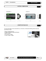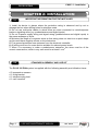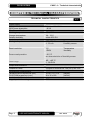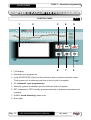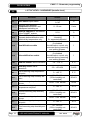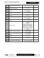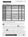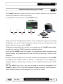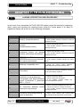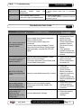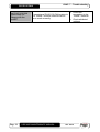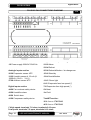
1
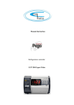
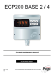
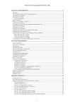
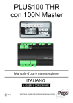
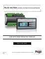
PLUS 100 PAN CONTROL SYSTEM FOR DOUGH-RETARDES
Use and maintenance manual
READ AND KEEP
REV. 02-15
ENG
ELECTRICAL BOARDS FOR REFRIGERATING INSTALLATIONS
PLUS 100 PAN
PLUS 100 PAN
CONTENTS
INTRODUCTION
Page 4
Page 4
Page 5
Page 5
1.1
1.2
1.3
1.4
General
Product ID codes
Overall dimensions
Identification data
INSTALLATION
Page 6
Page 6
2.1
2.2
Important information for installer
Standard assembly and use kit
FUNCTIONS
Page 7
3.1
Functions managed by the PLUS 100 PAN
TECHNICAL CHARACTERISTICS
Page 8
Page 9
4.1
4.2
Technical characteristics
Warranty terms
CHAP. 1
CHAP. 2
CHAP. 3
CHAP. 4
PARAMETER PROGRAMMING
Page 10
Page 11
Page 12
Page 12
Page 12
Page 13
Page 14
Page 15
Page 16
5.1
5.2
5.3
5.4
5.5
5.6
5.7
5.8
5.9
Control panel
LCD display
General features
Key to symbols
Setting and displaying the set-points
Level 1 programming
List of Level 1 variables
Level 2 programming
List of Level 2 variables
CHAP. 5
USING THE UNIT
Page 18
Page 18
Page 19
Page 19
Page 19
Page 20
Page 21
Page 25
6.1
6.2
6.3
6.4
6.5
6.6
6.7
6.8
Cold/hot: maintaining room temperature
Humidifying/dehumidifying: maintaining room humidity
Ventilation
Air changeover
Clock / calendar
Manual cycles
Automatic cycles
Supervision/monitoring system TeleNET
CHAP. 6
TROUBLESHOOTING
Page 26
Page 27
7.1
7.2
Alarms: description and procedures
Troubleshooting guide
CHAP. 7
APPENDICES
Page 29
Page 30
A.1
A.2
EC declaration of conformity
PLUS 100 PAN connections diagram
Rev. 02-15
USE AND MAINTENANCE MANUAL
Pag. 3
CHAP. 1 - Introduction
PLUS 100 PAN
CHAPTER 1: INTRODUCTION
1.1
GENERAL
The PLUS 100 PAN system allows the user to control temperature and humidity. The
system consists of the 100 MASTER unit, on which all the electrical connections are
made, and the PLUS 100 PAN control panel, which features a large LCD display to
provide rapidly available, complete information on room status. The system allows the user
to cool, heat and ventilate the room, switch the room light on/off, humidify it, effect an air
changeover, dehumidify it, defrost it and control alarms.
1.2
PRODUCT ID CODES
PLUS100 PAN ……………………………. control of temperature and humidity for
pause-leavening applications.
Pag. 4
USE AND MAINTENANCE MANUAL
Rev. 02-15
CHAP. 1 - Introduction
PLUS 100 PAN
OVERALL DIMENSIONS
1.3
IDENTIFICATION DATA
1.4
The unit described in this manual has, on its side, an ID plate showing all the relevant
identification data:
• Name of Manufacturer
• Code and model of electrical board
• Serial number
• IP protection rating
• Power supply voltage
Rev. 02-15
USE AND MAINTENANCE MANUAL
Pag. 5
PLUS 100 PAN
CHAP. 2 - Installation
CHAPTER 2: INSTALLATION
2.1
IMPORTANT INFORMATION FOR THE INSTALLER
1. Install the device in places where the protection rating is observed and try not to
damage the box when drilling holes for wire/pipe seats.
2. Do not use multi-polar cables in which there are wires connected to inductive/power
loads or signalling wires (e.g. probes/sensors and digital inputs).
3. Do not fit power supply wiring and signal wiring (probes/sensors and digital inputs) in
the same raceways or ducts.
4. Minimise the length of connector wires so that wiring does not twist into a spiral shape
as this could have negative effects on the electronics.
5. Fit a general protection fuse upstream from the electronic controller.
6. All wiring must be of a cross-section suitable for relevant power levels.
7. When it is necessary to make a probe/sensor extension, the wires must be of the
correct cross-section, which in any case must be at least 1 mm2.
STANDARD ASSEMBLY AND USE KIT
2.2
The PLUS 100 PAN system is supplied with the following assembly and utilisation items:
n°2 temperature sensors
n°1 fixing bracket
n°1 telephone plug lead
n°1 user’s manual
Pag. 6
USE AND MAINTENANCE MANUAL
Rev. 02-15
CHAP. 3 - Functions
PLUS 100 PAN
CHAPTER 3: FUNCTIONS
3.1
FUNCTIONS CONTROLLED BY THE PLUS 100 PAN
- Display and adjustment of temperature and humidity settings (neutral zone).
- Activation/deactivation of stand-by mode.
- Sensor alarm/warning signals.
- Adjustment of differential temperature and humidity parameters.
- Adjustment of air changeover control parameters.
- Adjustment of defrosting parameters.
- Adjustment of fan parameters.
- Display of output status.
- Simultaneous display of temperature and humidity values.
- Automatic program management with automatic variation of temperature and humidity
settings over time.
- Clock function
Rev. 02-15
USE AND MAINTENANCE MANUAL
Pag. 7
CHAP. 4 – Technical characteristics
PLUS 100 PAN
CHAPTER 4: TECHNICAL CHARACTERISTICS
TECHNICAL CHARACTERISTICS
Power supply
Voltage
MAX power absorption
Climatic conditions
Working temperature
Storage temperature
Relative humidity
Input characteristics
Analogical inputs
4.1
230 V~ ± 10% 50 Hz
~ 8 VA
-10 - 60°C
-30 - 70°C
below 90% RH
NTC 10K 1%
4…20 mA
Temperature sensor
Humidity sensor
Read resolution
1°C
1 RH%
Temperature
Humidity
Sensor read precision
± 0.5 °C
see characteristics of humidity sensor
Read range
-45…+45 °C
0…99 RH%
Output characteristics
Outputs on relay
1 output on terminal N.A. 30A (AC1) 230 V AC
9 outputs on terminal N.A. 16A (AC1) 230 V AC
Dimensional characteristics
100 MASTER box dimensions (mm)
PLUS PAN keypad box (mm)
Insulation characteristics
Keypad protection rating
Pag. 8
121,5 x 71 x 175
98 x 35 x 180
(HxDxL)
(HxDxL)
IP55
USE AND MAINTENANCE MANUAL
Rev. 02-15
CHAP. 4 – Technical characteristics
PLUS 100 PAN
WARRANTY CONDITIONS
4.2
PLUS 100 electronic controllers are covered by a 24-month warranty against all
manufacturing defects, valid from date of delivery. If the system malfunctions as a result of
tampering, impact or improper installation the warranty will automatically be rendered null
and void. It is strongly recommended that you observe all instructions/information
regarding the technical characteristics of the device.
WARNING !
Any modifications made to wiring and/or internal components or any tasks
carried out in a way that fails to comply with the information/instructions in this
manual shall not only render the warranty null and void immediately but may
also lead to malfunctions, irreparable damage, serious injury or put
persons/objects in danger.
PEGO S.r.l. declines any responsibility for possible errors or inaccuracies
written in this manual as a result of printing or transcription errors.
PEGO S.r.l. reserves the right to modify its products as it deems necessary
without altering its main characteristics. Each new release of a PEGO user
manual replaces previous ones.
Rev. 02-15
USE AND MAINTENANCE MANUAL
Pag. 9
CHAP. 5 - Parameter programming
PLUS 100 PAN
CHAPTER 5: PARAMETER PROGRAMMING
CONTROL PANEL
1
2
1. LCD display.
5.1
3
4
5
6
7
8
2. Automatic cycle progress bar.
3. Cycle START/STOP (hold for a few seconds to start or stop an automatic cycle) /
Timer (press once to show day and time of end of cycle in progress).
4. UP (Automatic cycle programming).
5. Stand-by (system at standstill, does not interrupt cycle in progress).
6. SET temperature / SET humidity (press successively to alternate temperature and
humidity).
7. DOWN, forced defrosting, alarm mute.
8. Room light.
Pag. 10
USE AND MAINTENANCE MANUAL
Rev. 02-15
CHAP. 5 - Parameter programming
LCD DISPLAY
5.2
1
6
PLUS 100 PAN
7
2
8
9
10
3
11
12
13
4
14
15
5
16
1. Progress of PHASE 1 (cooling duration set by final user, physically occupies
sectors n° 1, 2, 3, 4, 5).
2. Progress of PHASE 2 (maintenance, so-called elastic phase, physically occupies
sectors n° 6, 7, 8, 9, 10).
3. Progress of PHASE 3 (leavening, duration set by final user, physically occupies
sectors n° 11, 12, 13, 14, 15, 16).
4. Progress of PHASE 4 (product ready settling, max. duration 4 hours, occupies the
last sectors n° 17, 18, 19, 20).
5. Relative ambient humidity / parameter values / error codes.
6. Ambient temperature / parameter values.
7. Programming (controller is in programming mode).
8. Cooling (flashes if called for dehumidification only).
9. Heating (flashes if called for dehumidification only).
Rev. 02-15
USE AND MAINTENANCE MANUAL
Pag. 11
17
CHAP. 5 - Parameter programming
PLUS 100 PAN
10. Humidification.
11. Dehumidification.
12. Defrosting.
13. Evaporator fans (both high and low speed).
14. Light.
15. Alarm.
16. Stand-by (light on continuously - controller ON, light flashing, controller in STANDBY).
17. Time / date / time parameter values.
GENERAL
5.3
To enhance safety and simplify the operator’s work, the PLUS 100 PAN system has two
programming levels; the first level (Level 1) is used to configure the frequently-modified
SET-POINT parameters. The second programming level (Level 2) is for general parameter
programming of the various controller work modes.
It is not possible to access Level 2 programming directly from Level 1: you must exit the
programming mode first.
KEY TO SYMBOLS
5.4
For purposes of practicality the following symbols are used:
• (t) the UP key is used to increase values and in programming the cycles;
• (u) the DOWN key is used to decrease values and mute the alarm.
5.5
SETTING AND DISPLAYING THE SET-POINTS
1. Press the SET key
to display the current SET-POINT (temperature or humidity).
2. Hold down the SET key and press the (t) or (u) keys to modify the SET-POINT.
3. Release the SET key to return to room temperature display: the new setting will be
saved automatically.
Pag. 12
USE AND MAINTENANCE MANUAL
Rev. 02-15
CHAP. 5 - Parameter programming
PLUS 100 PAN
LEVEL 1 PROGRAMMING (User level)
5.6
To gain access to the Level 1 configuration menu proceed as follows:
1. Press the (t) and (u) keys simultaneously and keep them pressed for a few seconds
until the first programming variable appears on the display.
2. Release the (t) and (u) keys.
3. Select the variable to be modified using the (t) or (u) key.
4. When the variable has been selected it is possible:
• Display the setting in the respective sector of the display (5 or 17 page 11)
• To modify the setting by pressing the SET key
and the (t) or (u) keys.
When configuration values have been set you can exit the menu by pressing the (t) and
(u) keys simultaneously for a few seconds until the room temperature reappears;
alternatively, do not press any key for a few seconds.
5. The new settings are saved automatically when you exit the configuration menu.
Rev. 02-15
USE AND MAINTENANCE MANUAL
Pag. 13
CHAP. 5 - Parameter programming
PLUS 100 PAN
5.7
LIST OF LEVEL 1 VARIABLES (User level)
LABEL
d-t
d-U
d-d
d0
d1
d4
d5
d6
F5
F6
tEu
MEANING
Temperature difference compared to main
SET-POINT
Differential for Humidification compared to
main SET-POINT
Differential for Dehumidification compared to
main SET-POINT
Air changeover interval (parameter only active
during the leavening phases)
Air changeover duration (parameter only
active during the leavening phases)
Defrosting interval, interval between one
defrosting and the next
d4=0 no defrosting. (parameter only active
during cooling and maintenance stages
Max defrost duration time
End of defrosting temperature SET-POINT.
Defrosting is not executed if the temperature
read by the defrosting sensor is higher than the
end of defrosting setting.
(in the event of a faulty sensor defrosting is
timed)
Fan stop time (Expressed in minutes)
At the end of defrosting the fans can be kept at
standstill for a further set time. This time begins
at the end of defrosting (parameter active only
in the cooling and maintenance phases)
Fan shutdown temperature. (Expressed in °C.)
At the end of defrosting or at start-up the fans
can be kept at standstill until the evaporator
sensor temperature setting is reached.
(parameter active only in the cooling and
maintenance phases)
Defrosting sensor temperature display
(evaporator)
RANGE
DEFAULT
1÷10 °C
2°C
1÷10 rH%
5 rH%
1÷10 rH%
5 rH%
00…24
hours
0:00
1….60 min
6 min
0..24 hours
8 hours
1..60 min
20 min
-35 ÷ 45 °C
12°C
0 - 10 min’
2 min
-20 ÷ 30 °C
23 °C
--
Read only
DMy
Current date
dd:mm:yy
HMS
Current time
0:00 .. 23:59
hh:mm
Pag. 14
USE AND MAINTENANCE MANUAL
Rev. 02-15
CHAP. 5 - Parameter programming
PLUS 100 PAN
LEVEL 2 PROGRAMMING (Installer level)
5.8
To access the second programming level press the UP (t) and DOWN (u) keys and the
LIGHT
key simultaneously for a few seconds.
When the first programming variable appears the system automatically goes to stand-by.
1. Select the variable to be modified by pressing the UP (t) and DOWN (u) keys.
When the parameter has been selected it is possible to:
2. View the setting in the respective sector of the display (5 or 17, page 11).
3. Modify the setting by holding the SET key
down and pressing the (t) or (u) key.
4. When configuration settings have been completed you can exit the menu by pressing
the (t) and (u) keys simultaneously and keeping them pressed until the room
temperature value reappears.
Exit from Level 2 is not automatic, even if keys are left untouched for a long time.
5. Changes are saved automatically when you exit the configuration menu.
6. To enable the electronic controller press the STAND-BY key
Rev. 02-15
USE AND MAINTENANCE MANUAL
.
Pag. 15
CHAP. 5 - Parameter programming
PLUS 100 PAN
5.9
LABEL
AC
C1
Ad
dEU
LIST OF LEVEL 2 VARIABLES (Installer level)
MEANING
Door switch input status
Minimum time between
compressor shutdown and
subsequent switching on
Network address for connection
to the TeleNET system
Dehumidification mode select.
Separate dehumidification calls
heat/cold by temperature only
EnU
Humidification enable
End
Dehumidification enable
CAt
Ambient sensor value correction
CAU
Humidity sensor value
correction
St1
SU1
t1
St2
SU2
t2
St3
SU3
Pag. 16
RANGE
DEFAULT
0= NO
1= NC
0
0...15 min
0 min
0÷31
0
0= cooling
1=heating
2= separated dehumid.
1= enabled
0= disabled
Humidification control only
executed during leavening
and settling phases.
1= enabled
0= disabled
Humidification control only
executed during leavening
and settling phases.
2
1
1
-10…+10 °C
0 °C
-20…+20 rH%
0 rH%
First leavening step temperature
set-point
0…+45 °C
5 °C
First leavening step humidity setpoint
50…99 rH%
(50%=humidity not
controlled)
85 rH%
00:00…2:00 hh:mm
00:30
0…+45 °C
10 °C
50…90 rH%
(50%= humidity not
controlled)
80 rH%
00:00…2:00 hh:mm
00:30
0…+45 °C
16 °C
50…99 rH%
(50%= humidity not
controlled)
80 rH%
First leavening step duration
hh:mm
Second leavening step
temperature set-point
Second leavening step humidity
set-point
Second leavening step duration
hh:mm
Third leavening step temperature
set-point
Third leavening step humidity setpoint
USE AND MAINTENANCE MANUAL
Rev. 02-15
CHAP. 5 - Parameter programming
t3
Third leavening step duration
hh:mm
Fourth leavening step
temperature set-point
PLUS 100 PAN
00:00…2:00 hh:mm
00:30
0…+45 °C
16 °C
50…99 rH%
(50%= humidity not
controlled)
80 rH%
00:00…2:00 hh:mm
00:00
0…+45 °C
16 °C
SU5
Fifth leavening step humidity setpoint
50…90 rH%
(50%= humidity not
controlled)
80 rH%
t5
Fifth leavening step duration
hh:mm
00:00…2:00 hh:mm
00:00
St4
SU4
t4
St5
Fourth leavening step humidity
set-point
Fourth leavening step duration
hh:mm
Fifth leavening step temperature
set-point
Hr
Humidity control
dE
Evaporator sensor exclusion
EnC
Str
Enables cold (cooling) during
manual, automatic leavening and
settling.
Settling phase temperature setpoint
SUr
Settling phase humidity set-point
d9
Defrost enable during cooling
Rev. 02-15
Hr = 1 humidity control
enabled
Hr= 0 humidity control
disabled. Humidity sensor
can be disconnected
without error, the display
shows evaporator sensor
instead of humidity (if
dE=0)
0 = sensor present
1 = sensor absent
1
0
0 = cold disabled
1 = cold enabled
1
0…+45 °C
12 °C
50…99 rH%
80 rH%
0 = defrosting disabled
1 = defrosting enabled
0
USE AND MAINTENANCE MANUAL
Pag. 17
PLUS 100 PAN
CHAP. 6 - Using the unit
CHAPTER 6: USING THE UNIT
6.1
COLD/HEAT: MAINTAINING AMBIENT TEMPERATURE
Heating/cooling is neutral-zone controlled on the basis of the temperature set-point (key 6
) and the temperature differential (parameter d-t).
Cooling is activated when the set + differential threshold is passed and stays on until the
set-point is reached.
Heating is activated when the setting – differential threshold is reached and stays on until
the set-point is reached.
6.2
HUMIDIFICATION/DEHUMID.: MAINTAINING AMBIENT HUMIDITY
Humidity and dehumidification are neutral-zone controlled during the leavening,
maintenance and settling phases only, and only if the programmed set-point is greater
than the settable minimum *(50%) on the basis of the humidity set-point (key 6
) and
the differential for Humidification (parameter d-U) and differential for Dehumidification
(parameter d-d).
Humidification is activated below the set – differential for Humidification (parameter dU) threshold and stays on until the set-point is reached.
Dehumidification is activated above the set + differential for Dehumidification
(parameter d-d) threshold and stays on until the set-point is reached.
Humidity control can be disabled via the Hr (relative humidity) parameter, or by setting the
set point to the minimum R.H.% 50 = humidity control disabled (display only).
Dehumidification alone be disabled via the End parameter.
Humidification alone can be disabled via the EnU parameter.
There are three dehumidification modes (dEU parameter ):
1. Dehumidification with cooling (cold is called to dehumidify, heat is added only to
maintain ambient temperature).
2. Dehumidification with heating (heat is called to dehumidify, cold is added only to
maintain ambient temperature).
If the difference in temperature is, with respect to the setting, greater than 5°C
(during dehumidification with the compressor and elements) 5°C, the unit with the
Pag. 18
USE AND MAINTENANCE MANUAL
Rev. 02-15
CHAP. 6 - Using the unit
PLUS 100 PAN
greater value shuts down to prevent any overheating or over-cooling which could
damage the product.
3. Separated dehumidification (dehumidification output activated only but without
cold/heat call).
(*) if the humidity set point is set to the minimum (50%) neither dehumidification nor
humidification are controlled
VENTILATION
6.3
Fan speed is regulated by two digital outputs (high/low speed) and run at high speed with
the cold call during the cooling and maintenance phases and continuously at low speed
during the leavening and settling phases.
Fans are always off during defrosting.
Variants can be controlled via parameters F5 and F6.
AIR CHANGEOVER
6.4
Air changeover is controlled via parameters d0 and d1.
Use d0 to establish the interval between one air changeover and another: the counter
starts its count from zero at the start of every manual or automatic leavening cycle. If d0 =
00 no air changeover is carried out.
Use d1 to establish the duration of the air changeover.
Cooling, heating, humidification and dehumidification are not activated during air
changeover.
CLOCK / CALENDAR
6.5
Current time and date can be adjusted via the dMY and HMS parameters.
The current time is shown on the LCD display.
Rev. 02-15
USE AND MAINTENANCE MANUAL
Pag. 19
PLUS 100 PAN
MANUAL CYCLES
6.6
The controller recognises the manual cycles (only hot or only cold) from the temperature
setting only when in stop mode, not in stand-by.
If the set-point is less than or equal to 10°C the controller recognises the manual cold
cycle. It will consequently run the fans simultaneously with the compressor call and
execute the programmed defrosts as per the parameter settings; humidity control will not
be executed.
If the set-point is higher than 10°C the controller recognises the manual hot cycle.
Consequently the fans are run continuously, humidity is controlled according to the RH%
setting and the defrost cycles are not executed.
Pag. 20
USE AND MAINTENANCE MANUAL
Rev. 02-15
CHAP. 6 - Using the unit
PLUS 100 PAN
AUTOMATIC CYCLES
6.7
It is possible to set four automatic pause-leavening cycles each with fully independent
automatic programmed leavening, and a maintenance-only cycle (riC 0) with cooling start.
The four cycles have the following characteristics: cycle n°1 is carried out the same day
(12 hrs); cycle n°2 is for the next day (24 hrs); cycle 3 for the second successive day (48
hrs); and cycle 4 for the third successive day after the (72 hrs).
To enter the recipes programming mode press key 4
until the letters riC appear on
the temperature display and the numbers 01 … 04 on the RH% display. Use keys 4
and 7
to select the recipe to be programmed, press key 3
to enter
programming mode for the selected recipe. The 20 segments at the top of the unit should
all be off: only one of the first four will remain on to remind you of the recipe you are
programming. To program the data proceed as follows:
1. Use the (t) or (u) key to select the variable to be modified. After selecting the desired
variable it will be possible to:
2. View the value on the respective sector of the display (5 or 17 page 11).
3. Modify the setting by pressing or maintaining the SET key
and pressing the (t)
or (u) key.
Exit programming mode [from the product ready day window (LI6)] by keeping key 4
pressed for 2 seconds; in any case the unit will exit programming mode if no keys are
touched for 30 seconds.
Rev. 02-15
USE AND MAINTENANCE MANUAL
Pag. 21
CHAP. 6 - Using the unit
PLUS 100 PAN
CYCLE PROGRAMMING DATA:
DISPLAY
TEMP.
DISPLAY RH%
AC1
Cooling temperature
-20°C…..0°C.
Off
AC2
Off
Cooling time
00:00:00….29:59:00
Co1
Co2
Li1
Maintenance
temperature
-5°C…..15°C.
Hr% Maintenance
50%….99.0%
Final leavening
temp.
10°C…..+45°C.
Default
recipe 1
Default
recipe 2
-7
-10
04:00:00
05:00:00
Off
-2
-4
Off
50
50
Off
27
30
04:00:00
05:00:00
80
85
02:00:00
02:30:00
0
0
DISPLAY TIME
Li2
Off
Leavening duration
t1+t2+t3+t4+t5..09:59:00
Li3
Final leavening
RH% 50%….99.9%
Off
Li4
Off
Product ready time
00:00….23:59:00
Li5
End-of-cycle settling
1=Yes .… 0=No
Off
Product ready day
01:01:04….31:12:99 (read
/
/
only)
N.B. the 00 cycle is dedicated to a cool-only cycle that consists of an initial cooling phase
Li6
Off
followed by a switch to maintenance for an indefinite period; the programmable data items
for this recipe are therefore AC1; AC2; Co1; Co2.
Once programming has been completed you can start a cycle by pressing key 3
for a few seconds. The display asks which recipe is to be used (riC 00 … riC 04).
Select the desired recipe via the up/down keys: when key 3
is pressed again the
product ready (oven-ready) time and day are displayed for 5 seconds. If the shown data is
correct there is no need to carry out any further tasks and the controller makes subsequent
checks and then starts the cycle. If, however, the data is incorrect stop the cycle by
pressing key 3
, enter the recipe, modify the incorrect data and restart the cycle.
The controller makes a quick calculation to see if the cycle duration time is
compatible with the “product ready” time and day. If everything is compatible the cycle
begins and the first segment lights up. If, instead, there are incompatibilities the controller
goes to stand-by, the buzzer sounds and the EP message appears on the display to
Pag. 22
USE AND MAINTENANCE MANUAL
Rev. 02-15
PLUS 100 PAN
indicate erroneous programming. To switch off the buzzer press key 7
. The
progress of the cycle is highlighted at the top of the unit as follows:
Phase 1: cooling n° 5 segments;
Phase 2 maintenance n° 5 segments;
Phase 3 leavening n° 6 segments;
Phase 4 settling (where enabled) n° 4 segments.
If a settling phase is enabled sector 19 will light up at the cycle START to remind the user
that, when the product ready time is reached, the cycle will be completed by a settling
phase. It goes off at the start of the settling phase (i.e. when segment n° 17 lights up).
While a complete cycle is being carried out the number of the recipe “riC
01” can
be viewed on the RH% display and the baking day/time displayed alternately on the clock
display (17) for a few seconds by pressing key 3
briefly. While a complete cycle is in
progress you can view and modify the recipe in use by pressing key 4
for 2
seconds: you can vary temperature and humidity but not the duration times of the
different stages.
At the end of the final leavening cycle (if settling is not enabled) the controller goes
to stand by. The buzzer sounds and the segment bar flashes to indicate that the cycle is
over. Buzzing/flashing stops automatically after 1 minute or when key 7
is pressed.
The user can vary temperature and humidity set-points alternately at any time
during the active cycle (manual heat/cool cycles included) via key 6
: note, however,
that during a complete cycle variation of the set-point is relative to the phase in progress.
The first phase is known as cooling (cold is produced and “accumulated”). If the recipe has
a cooling time of 0:00 the controller immediately goes to the maintenance phase at the
start if the cycle.
There then follow: maintenance, intermediate leavening, final leavening and (where
enabled) settling.
N.B. the end of the cycle (Li4 - product ready time) is defined by the end of the final
leavening phase, not the settling cycle.
Rev. 02-15
USE AND MAINTENANCE MANUAL
Pag. 23
PLUS 100 PAN
The cooling phase is characterised by:
•
Temperature set-point
•
Duration of the phase
The maintenance phase is characterised by:
•
Temperature set-point
•
Humidity set-point
The leavening phase is characterised by:
•
Temperature set-point
•
Humidity set-point
•
Duration of the intermediate leavening phases via 2nd level parameters and overall
leavening duration programmed by final user. N.B. overall leavening duration can
never be less than the sum of the 5 parameter-programmed steps.
The settling phase is characterised by:
•
Duration in hours (2nd level parameter)
•
Temperature set-point (2nd level parameter)
•
Humidity set-point (2nd level parameter)
If a phase has time 0, it is not executed and the controller goes to the next phase.
Phase times continue even in the event of an electrical power failure or controller stand-by.
When an automatic cycle is in progress it is possible to check the number of the cycle in
use and the in-oven day / time by briefly pressing key 3
(CYCLE START); sector 17
of the display (DATE TIME) shows first day and then time.
Pag. 24
USE AND MAINTENANCE MANUAL
Rev. 02-15
PLUS 100 PAN
Supervision/monitoring system TeleNET
6.8
The TeleNET supervision system allows the user to create a historical room temperature
and humidity database via Personal Computer.
To configure the instrument, refer to the TeleNET manual.
Assign the PLUS 100 PAN system address via the configuration sequence by selecting
the Ad label from the 2nd programming level (installer level) and following the normal
address attribution criteria used for TeleNET.
Temperature as detected by the controller can be displayed at the TeleNET address Ad+1
by setting the module as TWMT (temperature acquisition module).
In this way the TeleNET supervision program can simultaneously display temperature and
relative humidity as measured by the PLUS 100 PAN and build up a record of both
parameters.
Example: if parameter Ad is set to 3, relative humidity can be displayed on the TeleNET
by assigning the TWMUR module to address 3; temperature can be displayed by
assigning address 4 (obtained by summing one to the parameter Ad=3) as the TWMT
module.
N.B. The address Ad+1 can, in any case, be used by any device connectable to the
TeleNET (in place of PLUS 100 PAN temperature display) except for TWMT modules to
which a different address must be assigned so as to avoid any conflict.
Rev. 02-15
USE AND MAINTENANCE MANUAL
Pag. 25
CHAP. 7 – Troubleshooting
PLUS 100 PAN
CHAPTER 7: TROUBLESHOOTING
ALARMS: DESCRIPTION AND PROCEDURES
7.1
In the event of any anomalies the PLUS 100 PAN system warns the operator by displaying
alarm codes and sounding the warning buzzer inside the control panel. If an alarm is
tripped the display will show one of the following messages:
ALARM CODE
E0
POSSIBLE CAUSE
PROCEDURE TO BE FOLLOWED
Temperature sensor not working • Check the temperature sensor
properly (stops the system)
• If the problem persists contact the technical
assistance service
E1
Humidity sensor not
properly
(stops humidity control)
working
• Check the humidity sensor
• If the problem persists contact the technical
assistance service
E2
Evaporator sensor not working • Check the evaporator sensor
• If the problem persists contact the technical
properly (defrostings scheduled)
assistance service
E3
EEPROM ALARM
• Switch off unit and switch back on
EEPROM memory error detected. • If the problem persists change the control
board
(all outputs deactivated)
E4
Software compatibility error
• Check for correct match between
MASTER board and control panel board
E6
Flat battery
• Contact the technical assistance service
to have the battery replaced
EC
Compressor
safeguard
(e.g.
overheat or excess pressure).
(Compressor and dehumidification
output deactivated if parameter
dEU = 0 or 1)
• Check compressor status
• Check compressor absorption
• If the problem persists contact the
technical assistance service
En
No connection between control • Check for presence of ferrite on sensors
• If the problem persists contact the technical
panel and control board
• Check connections between the two units
assistance service
EP
Pag. 26
Erroneous recipe programming
(goes to stand-by)
USE AND MAINTENANCE MANUAL
• Check recipe duration with product-ready
time and day at the moment of cycle START.
Rev. 02-15
CHAP. 7 - Troubleshooting
PLUS 100 PAN
EU
Humidifier alarm
(relevant
output
deactivate)
EF
Fan overheat safety device
(relevant output not deactivated)
does
• Check specific alarm type on humidifier
not control.
• Check fan absorption
• If the problem persists contact the technical
assistance service
TROUBLESHOOTING GUIDE
PROBABLE CAUSE
PROBLEM
Power supply fault (check connection
lead to control board).
Control board power supply not
The Control Panel does
connected.
not respond and the
Incorrect connection between Control
display is blank
Panel and Control Board (Panel power
supply probably inverted with RS-485
signal)
Incorrect connection between Control
The Control Panel does
Panel and Control Board.
not respond and the
Connection between Control Panel and
display reads En
Control Board interrupted
7.2
PROCEDURE TO BE
FOLLOWED
• Check that power
arrives at the Panel
and/or Control
Board terminals.
• Check connections
between Control
Panel and Control
Board.
• If the problem
persists contact the
technical assistance
service.
•
•
•
•
The PLUS 100 PAN
system generates false Sensor(s) connected incorrectly or faulty
alarms
•
The humidity sensor
does not display the
correct humidity value
Sensor is not connected properly.
Correct type of humidity sensor not
selected.
The PLUS 100 PAN
system does not
respond to the
parameters set on the
configuration
Incorrect parameter settings
Rev. 02-15
•
•
USE AND MAINTENANCE MANUAL
Invert RS-485 signal
lead connection.
Check connections
for continuity.
Check all
connections.
Check Control
Board connection
leads for continuity.
If the problem
persists contact the
technical assistance
service.
Check that sensor is
working properly
and that connection
is correct.
Check the system
configuration
settings.
Pag. 27
PLUS 100 PAN
The PLUS 100 PAN
system does not
dialogue with the
TeleNET
Pag. 28
CHAP. 7 - Troubleshooting
•
Connection of PLUS 100 PAN system to
the TeleNET module network has not
been made correctly
•
USE AND MAINTENANCE MANUAL
Check the
connection to the
TeleNET network.
Check attributed
address.
Rev. 02-15
Appendices
PLUS 100 PAN
APPENDICES
CE DECLARATION OF CONFORMITY
A.1
COSTRUTTORE / MANUFACTURER
PEGO S.r.l. Via Piacentina, 6/b 45030 Occhiobello (RO) – Italy –
Tel. (+39) 0425 762906 Fax. (+39) 0425 762905
DENOMINAZIONE DEL PRODOTTO / NAME OF THE PRODUCT
MOD.:
PLUS 100 PAN
IL PRODOTTO E’ CONFORME ALLE SEGUENTI DIRETTIVE CE:
THE PRODUCT IS IN CONFORMITY WITH THE REQUIREMENTS OF THE FOLLOWING EUROPEAN DIRECTIVES:
Direttiva Bassa Tensione (LVD):
Low voltage directive (LVD):
2006/95/CE
EC/2006/95
Direttiva EMC:
Electromagnetic compatibility (EMC):
2004/108/CE
EC/2004/108
LA CONFORMITA’ PRESCRITTA DALLA DIRETTIVA E’ GARANTITA DALL’ADEMPIMENTO A TUTTI GLI EFFETTI
DELLE SEGUENTI NORME (comprese tutte le modifiche):
THE CONFORMITY WITH THE REQUIREMENTS OF THIS DIRECTIVE IS TESTIFIED BY COMPLETE ADHERENCE
TO THE FOLLOWING STANDARDS (including all amendments):
Norme armonizzate:
European standards:
EN 60730-1, EN 60730-2-9, EN 61000-6–1, EN 61000-6–3
EN 60730-1, EN 60730-2-9, EN 61000-6–1, EN 61000-6–3
IL PRODOTTO E’ COSTITUITO PER ESSERE INCORPORATO IN UNA MACCHINA O PER ESSERE ASSEMBLATO
CON ALTRI MACCHINARI PER COSTITUIRE UNA MACCHINA CONSIDERATE DALLA DIRETTIVA: 2006/42/CE
“Direttiva Macchine”.
THE PRODUCT HAS BEEN MANUFACTURED TO BE INCLUDED IN A MACHINE OR TO BE ASSEMBLED
TOGHETER WITH OTHER MACHINERY TO COMPLETE A MACHINE ACCORDING TO DIRECTIVE: EC/2006/42
“Machinery Directive”.
Rev. 02-15
USE AND MAINTENANCE MANUAL
Pag. 29
Appendices
PLUS 100 PAN
PLUS100 PAN CONNECTIONS DIAGRAM
A.2
Power section
Outputs section (free-voltage contacts)
1-2 Power supply 230VAC 50/60 Hz
21-22 Alarm
23-24 Defrost
Analogic inputs section
25-26 Dehumidification / air changeover
29-30 Evaporator sensor NTC
15-16 Stand-by
31-32 Humidity sensor 4..20 mA (0100Rh%) (32=V+ 31=Y)
27-28 Ambient sensor NTC
13-14 Humidification
11-12 Room light
9-10 Evaporator fans low speed (*)
Digital inputs section
7-8 Evaporator fans high speed (*)
44-50 Fan overheat safety device
5-6 Heat
43-50 Humidifier alarm
3-4 Cold
42-50 Switch door
41-50 Compressor safety device
TeleNET section:
39 A line on 2TWRS485
40 B line on 2TWRS485
(*)High speed: terminals 7-8 close, terminals 9-10 open
Low speed: terminals 7-8 open, terminals 9-10 close.
Pag. 30
USE AND MAINTENANCE MANUAL
Rev. 02-15
PLUS 100 PAN
NOTES
Rev. 02-15
USE AND MAINTENANCE MANUAL
Pag. 31
PLUS 100 PAN
PEGO S.r.l.
Via Piacentina, 6/b
Dealer:
45030 OCCHIOBELLO –ROVIGOTel: 0425 762906
Fax: 0425 762905
www.pego.it
USE AND MAINTENANCE MANUAL
Pag. 32
e-mail: [email protected]
Rev. 02-15