1
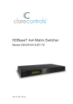
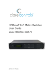
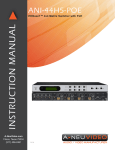
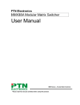
TEK-MHD44TP 79055 4x4 HDMI Matrix with HDBaseT Lite Outputs TEK-TPHD402PR User’s Manual December 30, 2013 Please read this manual carefully before using the system. Attention: This manual only includes operational instructions and specifications, and is not intended to be used for service. Specifications are subject to change without notice. Please ask your local dealer for detailed information. © Copyright 2013 - TEKVOX, Inc. No part of the contents of this book may be transmitted or reproduced in any form or by any means without the written permission of TEKVOX, Inc. All rights reserved. Please check website or contact local supplier for updates. www.tekvox.com Version 1.0 1.1 1.2 Firmware History Date Update Content 2013.05.29 First version. 2013.11.08 Added commands. 2013.11.11 Added commands. Operation Notice In order to ensure the proper use of the product and the user’s safety, please comply with the following items during installation and maintenance: The system must be properly connected to earth ground. Do not use ungrounded or two bladed plugs and ensure the alternating power supply ranged from 100v to 240v and from 50Hz to 60Hz. Do not operate the device in locations above 100° F and below 30°F. To avoid any damage by over heat, please provide adequate ventilation to radiate the heat when operating the device. The device should be turned off when in wet or humid areas. The AC power supply line should be disconnected from main power during the following operations: Remove or reinstall any component on the device. Disconnect or re-connect any connector on the device. Please do not attempt to remove the cover on the device. There are no serviceable components and high-voltage is present inside with risk of the electric shock. Do not splash any chemical product or liquid on or near the equipment. Table of Contents 1. DESCRIPTION ............................................................................................................ 1 2. FEATURES ................................................................................................................. 1 3. PACKAGE CONTENTS .............................................................................................. 1 4. FRONT AND REAR PANEL DESCRIPTION ............................................................. 2 4.1 FRONT PANEL OPERATION ..........................................................................................................................................2 4.2 REAR PANEL OPERATION ............................................................................................................................................2 4.3 RS-232 COMMUNICATION PORT.................................................................................................................................3 4.4 HDBASET TWISTED PAIR CABLE CONNECTION ...............................................................................................................4 5. SYSTEM DIAGRAM ................................................................................................... 5 6. SYSTEM OPERATION ............................................................................................... 6 6.1 FRONT PANEL BUTTON CONTROL.................................................................................................................................6 6.2 IR CONTROL ............................................................................................................................................................6 6.2.1 IR Remote Operation ....................................................................................................................................7 6.2.2 IR Operations ................................................................................................................................................8 6.3 RS-232 CONTROL ..................................................................................................................................................12 6.3.1 Commands ..................................................................................................................................................12 6.3.2 Control the HDBaseT 4x4 Matrix Switcher ..................................................................................................16 6.4 TCP/IP CONTROLLING .............................................................................................................................................18 6.5 IP CONFIGURATION .................................................................................................................................................18 6.5.1 Change IP/Serial Port ..................................................................................................................................19 6.6 CONNECTION AND CONTROL .....................................................................................................................................20 7. FIRMWARE UPDATING ........................................................................................... 20 8. TECHNICAL SPECIFICATION ................................................................................. 21 9. TROUBLESHOOTING & MAINTENANCE ............................................................... 22 10. WARRANTY ........................................................................................................... 22 TEK-MHD44TP 4x4 HDBaseT Matrix 1. Description The TEK-MHD44TP 79055 is a unique 4x4 HDMI matrix switcher with HDBaseT outputs with EDID & HDCP management. Included in the unit are IR and RS-232 inserters for the HDBaseT connections, and audio de-embedders with both analog and digital outputs. Any input can be routed to any output with support for high resolution 1080P and HD-3D. Breakaway audio is not supported. The HDBaseT output supports PoE and works with TPHD402PR to transmit HDMI, IR and RS-232 over a single Cat5e/Cat6 cable up to 200 feet. 2. Features HDMI resolution up to 1920*1200@60Hz including HD-3D HDCP Compliant and DVI compatible, supporting DVI 1.0 Powerful EDID and HDCP management HDBaseT Lite outputs, to transmit HDMI, IR & RS-232 up to 200 feet over a single Cat 5e/Cat 6 cable Output PoE provides power for all the receivers connected to the HDBaseT outputs Front panel Menu operation for configuration, control and status RS-232 control with simple ASCII commands IR control TCP/IP control (Optional) IR OUT signal switching follows with video signal, or can break away from video switching Supports remote control from receiver by IR & RS-232 Supports centralized IR control to control all the remote display devices Supports PCM, Dolby, and DTS 5.1 surround Source detection to provide power control for DVDs and Blur-rays. Standby mode operation to reduce energy and extend life. 3. Package Contents 1 MHD44TP 2 Mounting ears 1 Power adapter (DC48V) 1 IR remote 1 Power cord 1 RS-232 cable 1 CAT5e twisted pair 8 Captive screw connectors 4 table mount cushions TEKVOX, INC. 210.348.6565 1 www.tekvox.com 4. Front and Rear Panel Description 4.1 Front Panel Operation No. ① ② ③ ④ ⑤ Name Firmware Power Indicator IR Receiver LCD Indicator INPUTS/ Menu buttons ⑥ Function buttons ⑦ OUTPUTS Description Micro USB port for update firmware. Keep light when power on. Receive control signal from IR remote. Real-time shows system status. Normal mode: Input buttons, ranging from "1" to "4". Inquire mode: Press “AV” more than 3 seconds to enter this mode. to change different menus, to change different channels. AV button: To transfer AV and IR signal synchronously by the switcher. Example: To transfer both AV and IR signals from input channel No.1 to output channel No.3. Operation: Press buttons in this order “1”, “AV”, “3”. ALL outputs button: To transfer one input to all outputs. Example: To transfer both AV and IR signals from input channel No.1 to all output channels. Operation: Press buttons in this order “1”, “ALL” EDID management button: manually capture and copy the EDID data from output device to input port. Example: To capture and copy the EDID data from output channel No.4 to input channel No.2. Operation: Press buttons in this order “EDID”, “2”, “4” Output buttons, ranging from "1" to "4". To control the matrix from the front panel controls do the following: “Input Channel” + “AV” + “Output Channel” “Input Channel”: Fill with the number of input channel to be controlled. “Output Channel”: Fill with the number of output channels to be controlled. 4.2 Rear Panel Operation TEK-MHD44TP 4x4 HDBaseT Matrix No. Name ① IR ALL IN ② HDMI INPUTS ③ IR OUT ④ OUTPUTS ⑤ ⑦ ⑧ ⑨ RS-232 Power Indicator 48V DC GROUND TCP/IP ⑩ IR EYE ⑥ Description IR control signal input port, connect with IR receiver, pass through to all the HDBaseT ports to control the remote devices. Type A female HDMI connectors. Connect with IR transmitter, to send out the IR signal from the HDBaseT port. These IR OUTs make up a IR matrix with the IR INs on the HDBaseT receivers, and all can be switched synchronously with the AV signal or separately switching. IR IN: Connect with IR receiver, fixed IR input for the output, cannot be switched. It makes up an IR transmission with the IR OUT on the corresponding HDBaseT receiver. HDMI: Split HDMI output for local monitoring. COAX: HDMI de-embedded digital audio output. HDBaseT: Works with receivers using HDBaseT technology, such as TPHD402R, TPHD402PR. It can pass through AV, IR and RS-232 signal to 200 feet distance. PoE power is provided to operate the TPHD402PR. RS-232: RS-232 port to communicate with the RS-232 port on corresponding HDBaseT receiver. AUDIO: HDMI de-embedded stereo audio output The serial port for unit control, 9-pin female connector. Lights when Power is supplied to the unit. Connect with 48V DV power adaptor. Connect to grounding, make the unit ground well. TCP/IP port for unit control, optional function. Connect with extended IR receiver, use the IR remote to control MHD44TP. 4.3 RS-232 Communication Port TEKVOX, INC. 210.348.6565 3 www.tekvox.com Use this connector to operate the switcher using a third party control system. The RS-232 communication port is a DB9 female connector operating at 9600 baud. Pin 2 ---------- TX Out 3 ---------- RX In 5 ---------- Ground 4.4 HDBaseT Twisted Pair Cable Connection Always use a minimum of 30 feet Cat 5E or Cat 6 solid twisted pair cable. TIA/EIA T568A Cable Pin color green 1 white 2 green orange 3 white 4 blue blue 5 white 6 orange brown 7 white 8 brown 1st Ground 2nd Ground 3rd Group 4th Group 4--5 3--6 1--2 7--8 TIA/EIA T568B Cable Pin color orange 1 white 2 orange green 3 white 4 blue blue 5 white 6 green brown 7 white 8 brown 1st Ground 2nd Ground 3rd Group 4th Group 4--5 1--2 3--6 7--8 TEK-MHD44TP 4x4 HDBaseT Matrix 5. System Diagram TEKVOX, INC. 210.348.6565 5 www.tekvox.com 6. System Operation 6.1 Front Panel Button Control The operation examples are showed in 2.1 Front Panel. Here we make a brief introduction to the system inquire operations. Keep pressing the button “AV” for 3 seconds, it will enter into system inquire menu. Use Left and Right direction button two check the previous/next item. Function Items Check the connection status of inputs Check the connection status of outputs Correspondence between inputs and outputs Example In 1 2 3 4 Connect Y Y Y Y Out 1 2 3 4 Connect Y Y N N Description Y means the corresponding port is connected with input device, N means not. Y means the corresponding port is connected with output device, N means not. Out Input 1 2 3 4 1 2 3 3 Shows the correspondence between the 4 inputs and 4 outputs. Check if the input is with HDCP In HDCP 1 2 3 4 Y Y Y N Y means the input signal is with HDCP, N means not. Check if the output is with HDCP Out 1 2 3 4 HDCP Y Y Y N Y means the output signal is with HDCP, N means not. Check the output resolution Resolution Out 1 1920x1080 Use the UP and DOWN direction button to check all the 4 output resolutions. 6.2 IR Control The HDBaseT 4x4 matrix switcher can be controlled by its built-in IR receiver, through the IR EYE port by connecting with extended IR receiver or controlled remotely by a far-end IR device through one of its receivers. By using IR & HDBaseT transmission technology the HDBaseT 4x4 matrix switcher has the following features: Control far-end output device from local. Control local input/output device remotely. Control the HDBaseT 4x4 matrix switcher locally/remotely. TEK-MHD44TP 4x4 HDBaseT Matrix 6.2.1 IR Remote Operation Standby button, press it to enter in standby mode. Input channels, range from 1~4, IR signal switched following HDMI signal correspondingly. Menu buttons, AV and ALL buttons have the same function as the front panel. THROUGH: To transfer the signals directly to the corresponding output channels Example: Press “3”, “THROUGH”, the result will be IN 3OUT 3. Press “ALL”, “THROUGH”, the result will be: 11, 22, 33, 44 Output channels, range from 1~4. Each channel has 1 IR IN, 1 COAX, 1 HDBaseT, 1 RS232, and 1 AUDIO outputs, and channel No.1 & No.2 has 1 HDMI output. TEKVOX, INC. 210.348.6565 7 www.tekvox.com 6.2.2 IR Operations IR Matrix Switching By using the 4 “IR OUT” ports and the “IR IN” ports of the far-end receivers, the HDBaseT Matrix can be used as an IR router. Commands can be sent to the Matrix for the IR to follow the video or to switch separately. The IR signal received by an HDBaseT receiver is transmitted to a selected IR port (IR OUT) on the matrix switcher received by a controlled device. See figure below: Switching Operation: a) Sending command [x1]R[x2]. (reference to 6.3 RS-232 Control): x1: Corresponds to one of the 4 IR OUT ports of the matrix x2: Corresponding to an HDBaseT receiver Example command: “3R2.” transfers IR signal received from Receiver 2 to IR OUT port 3. b) Using IR remote: Input channelbutton IROutput channel Example Press buttons “3”, “IR”, “1” in order to transfer IR signal received from Receiver 3 to IR OUT port 1. Note: Multiple receivers cannot be selected to the same IR output. TEK-MHD44TP 4x4 HDBaseT Matrix IR Carrier Enforcing: a) IR carrier must be present on the HDBaseT receiver for the IR signal to be transferred to the IR OUT port of the matrix. b) IR carrier must be present on the IR ALL IN port of the matrix for the IR signal to be transferred to the IR OUT port of the matrix. c) If the IR receiver is connected with an HDBaseT receiver or IR ALL IN port of the matrix is not with IR carrier, you need to send the command “%0901.” to transfer the IR signal to IR OUT port. Control far-end output device from local To control a remote display from the local IR receiver, IR carrier must be present on the IR ALL IN port. The IR signal is transferred to the corresponding zone connected with an HDBaseT receiver that has an IR transmitter. When the IR receiver is connected to IR ALL IN port, the IR signal can be transferred to all 4 IR transmitters connected with HDBaseT receivers. See figure below: TEKVOX, INC. 210.348.6565 9 www.tekvox.com Control far-end device through IR ALL IN port The IR signal received from IR ALL IN port will be transmitted to all the four far-end HDBaseT receivers connected to HDBaseT ports on the matrix switcher. See figure below: TEK-MHD44TP 4x4 HDBaseT Matrix Control local device from remote User can control local devices such as Blu-rays or the HDBaseT Matrix remotely. When using the IR signal received from the HDBaseT receiver will be transmitted to the corresponding IR OUT port of the HDBaseT 4x4 matrix switcher. See figure below: Controlled by a Third-party IR Control Device Use the included IR converting cable (see as below) to connect the HDBaseT matrix to a third-party remote controller via a direct connection. Connect the red end to IR Input port on the HDBaseT matrix and the black end to IR Output port of the third-party control device. This allows the IR signal to be transmitted through the receivers to control a remote device. TEKVOX, INC. 210.348.6565 11 www.tekvox.com 6.3 RS-232 Control Communication protocol: Baud rate: 9600 Data bit: 8 Stop bit: 1 Parity bit: none Connector type: DB9 FM (Use Straight Through Cable) 6.3.1 Commands Command Types Command Codes /*Type; /%Lock; /%Unlock; System Command /^Version; /:MessageOff; /:MessageOn; Demo. Undo. [x]All. All#. All$. [x]#. [x]$. [x1] V[x2]. Operation Command [x1] B[x2]. [x1] R[x2]. Status. Save[X]. Recall[Y]. Clear[Y]. PWON. PWOFF. STANDBY. Functions Inquire the models information. Lock the keyboard of the control panel on the Matrix. Unlock the keyboard of the control panel on the Matrix. Inquire the version of firmware Turn off the feedback command from the com port. It will only show the “SWITCH OK”. Turn on the feedback command from the com port. Switch to the “demo” mode, 1->1, 2->2, 3->3 … and so on .The switching interval is 2 seconds. To cancel the previous operation. Transfer signals from the input channel [x] to all output channels Transfer all input signals to the corresponding output channels respectively. Switch off all the output channels. Transfer signals from the input channel [xq] to the output channel [x]. Switch off the output channel [x]. Transfer the AV signal from the input channel [x1] to the output channel [x2]. Transfer the AV and IR signal from the input channel [x1] to the output channel [x2]. Transfer the IR signal from the input channel [x1] to the output channel [x2]. Inquire the input channel to the output channels one by one. Save the present operation to the preset command [X], ranges from 0 to 9. Recall the preset command [Y]. Clear the preset command [Y]. Work in normal mode. Enter into standby mode. Enter into standby mode. TEK-MHD44TP 4x4 HDBaseT Matrix /%[Y]/[X]:[Z]. HDCP management command. [Y] is for input (value: I) or output (value: O). [X] is the number of one port, if the value of X is ALL, it means all ports. [Z] is for working status (Value: 1 or 0). Y=I & Z=1, means the input port is compliant with HDCP. Y=O & Z=1, means output with HDCP. Y=I & Z=0, means the input port is not compliant with HDCP. Y=O & Z=0, means output without HDCP. Enable HDMI audio output of port x. TEKVOX, INC. 210.348.6565 DigitAudioON[x]. X=1, 2, 3, 4, enable this one port. X=5, enable all the 4 ports. Disable HDMI audio output of port x. DigitAudioOFF[x]. X=1, 2, 3, 4, disable this one port. X=5, disable all the 4 ports. 13 www.tekvox.com Send embedded RS-232 commands to device at HDBaseT receiver. Y is for RS-232 port (connect with RS-232 port of HDBaseT receiver) Value = 1,2,3,4,5,A,B,C,D,E,F,G or H The value of Y is defined into the following meanings (in a given baud rate depended by the value of X): /+[Y]/[X]:******. a. Y = 1, 2, 3 or 4, send this command to the corresponding HDBaseT receiver to control far-end device. b. Y = 5, send this command to all HDBaseT receivers to control all far-end devices. c. Y = A, B, C or D d. Y = E, F, G or H For items c or d, send this command, it will be saved to the matrix switcher but taken without action to corresponding HDBaseT receiver. And its command function will be effective almost at the same time when you send the command PWON (for item c) or PWOFF (for item d). Note: A & E are for port 1. B & F are for port 2. C & G are for port 3. D & H are for port 4. X is for bound rate (Value ranges from 1 to 7, 1 is for 2400, 2 for 4800, 3 for 9600, 4 for 19200, 5 for 38400, 6 for 57600 and 7 for 115200) ***** is for data (max 48 Byte) The symbol “.” is the end of one command. If there are some symbols of “.” in one command, this case is allowed and the last one is the end. %0801. %0800. %0900. %0901. %0911. %9951. %9952. %9953. %9954. %9955. %9956. %9957. %9958. %9961. %9962. %9963. %9964. Automatically HDCP management. Manually HDCP management. Set as infrared carrier following mode. Set as infrared carrier enforcing mode. Reset to factory default. Check the command sent by port 1 when PWON. Check the command sent by port 2 when PWON. Check the command sent by port 3 when PWON. Check the command sent by port 4 when PWON. Check the command sent by port 1 when PWOFF. Check the command sent by port 2 when PWOFF. Check the command sent by port 3 when PWOFF. Check the command sent by port 4 when PWOFF. Check the system locking status. Check the status while in standby mode. Check the working mode of infrared carrier. Check the IP address (only for the PCB with GUI). TEK-MHD44TP 4x4 HDBaseT Matrix %9971. %9972. %9973. %9974. %9975. %9976. %9977. EDIDH[x]B[y]. EDIDG[x]. EDIDMInit. EDIDUpgrade[x] . UpgradeIntEDID[x]. EDIDM[X]B[Y]. Check the connection status of the inputs. Check the connection status of the outputs. Check the HDCP status of the inputs. Check the HDCP status of the outputs. Check the switching status. Check the output resolution. Check the status of digital audio of output channels. Copy the EDID from output port [x] to input port [y]. If the EDID data is effective and the audio part supports not only PCM mode, then force-set it to PCM mode. If the EDID data is not effective, then set it as initialized EDID data. Get EDID data from the output and display the output port number of X. Recover the factory default EDID data. Upgrade EDID data via the RS-232 port [X] is for input port. When the value of X is 5, upgrade all 4 input ports. When the switcher gets the command, it will show a message to send EDID file (.bin file). Operations will be canceled after 10 seconds. (Note 1) Select one type of EDID data and upgrade built-in EDID data. Supports 4 types of EDID data: 1. 1080P, 2D, PCM2.0 2. 1080P, 2D, 5.1 (audio) 3. 1080P, 3D, PCM2.0 4. 1080P, 3D, 5.1 (audio) [x] = 1, 2, 3 or 4 When the switcher gets the command, it will show a message to send EDID file (.bin file). Operations will be canceled after 10 seconds. Manually EDID switching. Copy the EDID data of output[X] to the input[Y]. Notes: 1. Please disconnect all the HDBaseT cables before sending command EDIDUpgrade[X]. 2. In above commands, “[”and “]” are symbols for easy reading and do not need to be typed in actual operation. 3. Please remember to end the commands with the ending symbols “.” and “;”. 4. Commands are case-sensitive. TEKVOX, INC. 210.348.6565 15 www.tekvox.com 6.3.2 Control the HDBaseT 4x4 Matrix Switcher To control the HDBaseT 4x4 matrix switcher connect its 9 pin female RS-232 port to a PC’s or control system’s RS-232 port. It is also possible to control the Matrix using one of the HDBaseT receiver’s RS-232 ports. Control the HDBaseT 4x4 Matrix Switcher from local Control the HDBaseT 4x4 Matrix Switcher from remote TEK-MHD44TP 4x4 HDBaseT Matrix Control Display or 3rd-Party Device from Local From a control system connected to the 9 pin female RS-232 port on the HDBaseT matrix use the embedded RS-232 command “/+[Y]/[X]:******.” to send data to a device at the HDBaseT receiver. This method does not allow for bi-directional control. Please reference to the detailed command description in 6.3.1 RS-232 Commands. Control far-end device from local Connect the RS-232 (3P captive screw) port in one zone to PC, and connect the controlled RS-232 device (3rd party device) to the corresponding (same zone as PC) receiver. This method allows for bidirectionally RS-232 data between controller and device at receiver. TEKVOX, INC. 210.348.6565 17 www.tekvox.com 6.4 TCP/IP Controlling The network port of TEK-MHD44TP is used for sending commands using TCP/IP control. These commands are sent the same as when using RS-232 control at TCP/IP port 4001. There is no Web based control for the unit. The Web interface is used for network configuration only. 6.5 IP Configuration To connect a computer to the network port you must use a crossover network cable or network switch. Set its IP address of the PC to the same IP VLAN as the default IP is address or the unit (192.168.0.178). Same IP section but cannot be 192.168.0.178 Enter the IP address 192.168.0.178 into Internet Explorer; you will see the LOGIN page as below: http://192.168.0 .178 Enter the password “88888”, and then you can enter the configuration page to configure the IP port, including the IP reset, PW reset etc. Note: Serial configuration cannot be changed. TEK-MHD44TP 4x4 HDBaseT Matrix 6.5.1 Change IP/Serial Port Select the tab “system info” to change the IP settings. Make certain the new IP address is written down. Best to keep the IP address settings listed on the on Matrix. You cannot get these settings from the front panel menus. Enter into right IP for each item, better has the same IP section with the router DO NOT Change This After configuration, reset device to use the new IP address for controlling Matrix. TEKVOX, INC. 210.348.6565 19 www.tekvox.com Change Serial Port and Network Port Number Select the tab “serial info” to change the serial settings. When finished, press the ally button. Set as 4001 6.6 Connection and Control To send IP commands to the TEK-MHD44TP connect using TCP/IP port 4001 and the set IP address of the unit. Use the standard serial commands from a control system or program that can send a complete command line. You cannot type the command using a Telnet program. 7. Firmware Updating To meet with the request of different users or add function in future, the firmware of TEK-MHD44TP can be upgraded via USB. When you need to upgrade it, download the latest upgrade file and use the update EXE software. Copy the EXE software to the PC and double chick the program to run the program. After running this program, click on Open and select the firmware file. Then press Connect USB. TEK-MHD44TP 4x4 HDBaseT Matrix 8. Technical Specification Video Input Video Output Input 4 HDMI Input Connector Female HDMI T.M.D.S. 2.9V/3.3V 100Ω (Differential) Input Level Input Impedance Video General Gain Video Signal 0 dB HDMI (or DVI-D) Output Output Connector 2 HDMI 4 HDBaseT Female HDMI Female RJ45(with LED indicators) Output Level T.M.D.S. 2.9V/3.3V Output Impedance 100Ω (Differential) Bandwidth Maximum Pixel Clock Switching Speed 6.75Gbit/s 165MHz Resolution Up to 1920 x 1200 200ns (Max.) or 1080P@60Hz Range Transmission 200 feet with PoE Distance EDID EDID data and manual EDID management Management HDCP Supports HDCP 1.3, auto and manual HDCP management. Audio General Stereo audio Output 4 3p captive screw connectors Output Signal Digital audio Connector 4 Coax (RCA) Coax Stereo Output 200 ohm Supports PCM, Dolby, DTS 5.1 Output Frequency 20Hz~20KHz Response Control Parts 4 IR OUT (green) 4 IR IN (black) 1 IR EYE (black) 1 TCP/IP (female RJ45) Control Ports Panel Control Front panel buttons 1 RS-232 (9 pin female D) 4 RS-232 (3p captive screw connectors) Default IR remote TCP/IP IR Works with PTNET2.2 Extend IR EYE Control General Input: 100VAC ~ 240VAC, Power Power 50/60Hz 48W Supply Consumption Output: DC48V,1.6A Temperature Humidity 10% ~ 90% -20 ~ +70℃ W19 x H1.73 x Case D9.25 IN. Product 1.8Kg Dimension (1U high, full Weight rack wide) Specifications are subject to change without notice. TEKVOX, INC. 210.348.6565 21 www.tekvox.com 9. Troubleshooting & Maintenance Most video issues are due to bad cables or the cable lengths are too long. Please check all connections before sending unit back for repair. Other issues may include improper EDID configuration. 10. Warranty TEKVOX, Inc. warrants this product against defects in workmanship and materials for a period of Three Years from the date of purchase. During the warranty period, if failure is caused from faulty workmanship and/or materials, TEKVOX, Inc. will, at its option, repair or replace said products or components, to whatever extent it shall deem necessary to restore said product to proper operating condition, provided that it is returned within the warranty period, with proof of purchase and description of malfunction. This Limited Warranty does not apply if fault is caused by misuse, improper handling, electrical or mechanical abuse, abnormal operating conditions or non-TEKVOX authorized modifications to said product. If it has been determined product is defective, please call TEKVOX and ask for an Applications Engineer at (210) 348-6565 (USA) to receive an RMA # (Return Material Authorization Number) to begin the repair process as quickly as possible. Units must be returned with prepaid shipping charges. Please insure package. If not insured you assume the risk of loss or damage during shipment. Returned units must include the serial number and a description of the problem, as well as the contact person in case there are any questions. TEKVOX, Inc. makes no further warranties either expressed or implied with respect to said product, or its quality, performance, or operation for any particular use. In no event will TEKVOX, Inc. be liable for direct, indirect, or consequential damages resulting from any defect in this product even if TEKVOX, Inc. has been advised of such damage. Please note that laws vary from state to state and country to country, and that some provisions of this warranty may not apply to you.