1
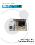
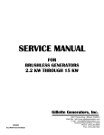
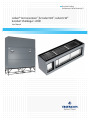
Precision Cooling
For Business-Critical Continuity™
Liebert® Air Economizer™ for Liebert DS™, Liebert CW™
& Liebert Challenger™ 3000
User Manual
GENERAL SAFETY GUIDELINES
Before beginning the installation of the Liebert Air Economizer, read all instructions, verify that all the parts
are included, and check the nameplate to be sure the Liebert Air Economizer voltage matches available utility power.
Follow all local and national codes.
! WARNING
Risk of electric shock. Can cause injury or death.
Disconnect all local and remote electric power supplies before working within.
! WARNING
Risk of unit falling over. Can cause death, injury and equipment damage.
The Liebert Air Economizer is top-heavy. Use extreme caution and care when moving and
installing this unit.
! CAUTION
Risk of piping and component rupture. May cause injury or equipment damage.
Closing service valves may isolate liquid refrigerant, causing high pressure and rupture of
piping. Do not close valves without following recommended procedures for repair,
maintenance and replacement of components. Install pressure relief valves in field piping
that may become isolated by service valves.
NOTE
This document is to be used together with site-specific documentation and documentation for
other parts of the system (heat rejection devices and cooling modules).
NOTE
Before any action that could cause a disturbance in the cooling system’s function is begun, the
facility manager MUST be informed. In addition, after the action is taken and the work is
finished, the facility manager MUST be informed.
TABLE OF CONTENTS
GENERAL SAFETY GUIDELINES . . . . . . . . . . . . . . . . . . . . . . . . . . . . . . . . . . . INSIDE FRONT COVER
1.0
PRODUCT DESCRIPTION . . . . . . . . . . . . . . . . . . . . . . . . . . . . . . . . . . . . . . . . . . . . . . . . . . .1
1.1
General Product Information. . . . . . . . . . . . . . . . . . . . . . . . . . . . . . . . . . . . . . . . . . . . . . . . . . . 1
1.1.1
Customer-Supplied Equipment and Ductwork. . . . . . . . . . . . . . . . . . . . . . . . . . . . . . . . . . . . . . 1
1.2
Equipment Inspection . . . . . . . . . . . . . . . . . . . . . . . . . . . . . . . . . . . . . . . . . . . . . . . . . . . . . . . . 2
1.3
Equipment Handling . . . . . . . . . . . . . . . . . . . . . . . . . . . . . . . . . . . . . . . . . . . . . . . . . . . . . . . . . 2
1.3.1
1.3.2
Handle the Liebert Air Economizer With Skid. . . . . . . . . . . . . . . . . . . . . . . . . . . . . . . . . . . . . . 3
Move the Liebert Air Economizer With a Forklift . . . . . . . . . . . . . . . . . . . . . . . . . . . . . . . . . . . 3
1.4
Unpack the Liebert Air Economizer . . . . . . . . . . . . . . . . . . . . . . . . . . . . . . . . . . . . . . . . . . . . . 3
2.0
INSTALLATION . . . . . . . . . . . . . . . . . . . . . . . . . . . . . . . . . . . . . . . . . . . . . . . . . . . . . . . . . .4
2.1
General Considerations . . . . . . . . . . . . . . . . . . . . . . . . . . . . . . . . . . . . . . . . . . . . . . . . . . . . . . . 4
2.2
Install the Liebert Air Economizer—Preliminary Steps . . . . . . . . . . . . . . . . . . . . . . . . . . . . . 4
2.2.1
2.2.2
2.3
Position the Liebert Air Economizer on a Liebert CW . . . . . . . . . . . . . . . . . . . . . . . . . . . . . . . . 4
Position the Liebert Air Economizer on a Liebert DS . . . . . . . . . . . . . . . . . . . . . . . . . . . . . . . . 5
Wiring the Liebert Air Economizer . . . . . . . . . . . . . . . . . . . . . . . . . . . . . . . . . . . . . . . . . . . . . . 9
2.3.1
2.3.2
Wire the Dampers. . . . . . . . . . . . . . . . . . . . . . . . . . . . . . . . . . . . . . . . . . . . . . . . . . . . . . . . . . . . 10
Outdoor Air and Return Air Temperature and Humidity Sensor Connections . . . . . . . . . . . 11
2.4
Adjust the Restricted Airflow Switch . . . . . . . . . . . . . . . . . . . . . . . . . . . . . . . . . . . . . . . . . . . 12
3.0
INSTALLATION CHECKLIST . . . . . . . . . . . . . . . . . . . . . . . . . . . . . . . . . . . . . . . . . . . . . . . . 13
4.0
OPERATION . . . . . . . . . . . . . . . . . . . . . . . . . . . . . . . . . . . . . . . . . . . . . . . . . . . . . . . . . . .14
4.1
Operational Condition . . . . . . . . . . . . . . . . . . . . . . . . . . . . . . . . . . . . . . . . . . . . . . . . . . . . . . . 15
4.1.1
4.2
System Overview . . . . . . . . . . . . . . . . . . . . . . . . . . . . . . . . . . . . . . . . . . . . . . . . . . . . . . . . . . . 15
4.2.1
4.2.2
4.2.3
4.2.4
4.3
Out of Service . . . . . . . . . . . . . . . . . . . . . . . . . . . . . . . . . . . . . . . . . . . . . . . . . . . . . . . . . . . . . . .
Fan Speed Control . . . . . . . . . . . . . . . . . . . . . . . . . . . . . . . . . . . . . . . . . . . . . . . . . . . . . . . . . . .
Variable Speed Fan Operation (VFD and EC Fan) . . . . . . . . . . . . . . . . . . . . . . . . . . . . . . . . .
Disable the Liebert Air Economizer . . . . . . . . . . . . . . . . . . . . . . . . . . . . . . . . . . . . . . . . . . . . .
17
22
22
22
Control Menu Settings . . . . . . . . . . . . . . . . . . . . . . . . . . . . . . . . . . . . . . . . . . . . . . . . . . . . . . . 22
4.3.1
4.4
Normal Operation. . . . . . . . . . . . . . . . . . . . . . . . . . . . . . . . . . . . . . . . . . . . . . . . . . . . . . . . . . . . 15
Liebert Air Economizer Status Screen . . . . . . . . . . . . . . . . . . . . . . . . . . . . . . . . . . . . . . . . . . . 23
Temperature Control Modes—P and PI . . . . . . . . . . . . . . . . . . . . . . . . . . . . . . . . . . . . . . . . . 23
4.4.1
4.4.2
4.4.3
4.4.4
Proportional Control. . . . . . . . . . . . . . . . . . . . . . . . . . . . . . . . . . . . . . . . . . . . . . . . . . . . . . . . . .
Proportional Integral Control . . . . . . . . . . . . . . . . . . . . . . . . . . . . . . . . . . . . . . . . . . . . . . . . . .
Integral Wind-up . . . . . . . . . . . . . . . . . . . . . . . . . . . . . . . . . . . . . . . . . . . . . . . . . . . . . . . . . . . .
Controller Tuning . . . . . . . . . . . . . . . . . . . . . . . . . . . . . . . . . . . . . . . . . . . . . . . . . . . . . . . . . . . .
23
23
23
24
5.0
MAINTENANCE . . . . . . . . . . . . . . . . . . . . . . . . . . . . . . . . . . . . . . . . . . . . . . . . . . . . . . . . . 26
6.0
TROUBLESHOOTING . . . . . . . . . . . . . . . . . . . . . . . . . . . . . . . . . . . . . . . . . . . . . . . . . . . . . 27
i
FIGURES
Figure 1
Figure 2
Figure 3
Figure 4
Figure 5
Figure 6
Figure 7
Figure 8
Figure 9
Figure 10
Figure 11
Figure 12
Figure 13
Figure 14
Figure 15
Liebert Air Economizer arrangement, typical. . . . . . . . . . . . . . . . . . . . . . . . . . . . . . . . . . . . . . . . . . 2
Dimensions—Liebert Air Economizer and Liebert CW models CW106D/114D . . . . . . . . . . . . . . . 6
Dimensions—Liebert Air Economizer and Liebert CW models CW026D-CW084D . . . . . . . . . . . . 7
Dimensions—Liebert Air Economizer and Liebert DS downflow units, 28-105kW (8-30 tons) . . . 8
Damper wiring connections—Liebert DS and Liebert CW units . . . . . . . . . . . . . . . . . . . . . . . . . . 10
Temperature and humidity sensor connections—Liebert DS and Liebert CW . . . . . . . . . . . . . . . 11
Supply limit thermistor wiring and restricted airflow switch location . . . . . . . . . . . . . . . . . . . . . 12
Operational ranges for chilled water systems and for compressor/chilled water systems . . . . . . 15
Air flow pattern of a Liebert Air Economizer system . . . . . . . . . . . . . . . . . . . . . . . . . . . . . . . . . . . 16
Liebert DS setpoints screen, page 4 of 6 . . . . . . . . . . . . . . . . . . . . . . . . . . . . . . . . . . . . . . . . . . . . . 18
Service/Economizer, page 1 of 3 . . . . . . . . . . . . . . . . . . . . . . . . . . . . . . . . . . . . . . . . . . . . . . . . . . . . 19
Outdoor sensor data screen . . . . . . . . . . . . . . . . . . . . . . . . . . . . . . . . . . . . . . . . . . . . . . . . . . . . . . . 20
Damper settings and limits screen . . . . . . . . . . . . . . . . . . . . . . . . . . . . . . . . . . . . . . . . . . . . . . . . . 21
Deactivation switch. . . . . . . . . . . . . . . . . . . . . . . . . . . . . . . . . . . . . . . . . . . . . . . . . . . . . . . . . . . . . . 22
Liebert iCOM Wellness menu, page 9 . . . . . . . . . . . . . . . . . . . . . . . . . . . . . . . . . . . . . . . . . . . . . . . 25
TABLES
Table 1
Table 2
Table 3
Dimensions—Liebert Air Economizer and Liebert CW models CW026D-CW084D . . . . . . . . . . . . 7
Liebert DS model dimensional data, 28-105kW (8-30 tons) . . . . . . . . . . . . . . . . . . . . . . . . . . . . . . . 8
Liebert Air Economizer troubleshooting . . . . . . . . . . . . . . . . . . . . . . . . . . . . . . . . . . . . . . . . . . . . . 27
ii
Product Description
1.0
PRODUCT DESCRIPTION
1.1
General Product Information
The Liebert Air Economizer is an option for Liebert DS downflow units, Liebert CW chilled water
downflow and Liebert Challenger 3000 downflow units. The Liebert Air Economizer uses cool outdoor
air in mild climates to condition indoor spaces. It is functional only on cooling units with Liebert
iCOM® controls that have been factory-wired and configured to accommodate the Liebert Air
Economizer.
The Liebert Air Economizer is supplied with electrical wiring for connection to the cooling unit,
outdoor air sensors, return air sensors and a temperature-and-humidity-sensing unit.
Special firmware is loaded into the primary cooling unit at the factory to permit the primary cooling
unit to control the Liebert Air Economizer.
NOTE
When upgrading the firmware for the primary cooling unit, either a Liebert DS downflow unit
or Liebert CW downflow unit, ensure that the new firmware includes the Liebert Air
Economizer controls. If in doubt, contact the factory.
1.1.1
Customer-Supplied Equipment and Ductwork
Installation and operation requires outside-air entry ductwork with louvers, screening and filtration
to prevent intrusion of precipitation, particulates, vermin and unauthorized entry (see Figure 1).
Proper installation also requires a customer-provided powered relief-air discharge to rid the structure
of the outside air drawn in for cooling. The relief-air discharge must be equivalent to the airflow of the
total of all cooling systems equipped with the Liebert Air Economizer.
A flange is provided to attach the Liebert Air Economizer to the outdoor air duct Figures 2, 3 and 4.
1
Product Description
Figure 1
Liebert Air Economizer arrangement, typical
Return Air Sensors
(Field-installed
above damper)
Plenum
Powered Outdoor
Relief Opening
(by others)
Room
Return
Air
Relief Air
Size collar according
to cooling unit opening
Room Relief Air
Discharge (sized and
provided by others)
Outdoor Air Sensor
(Field-installed inside duct;
labeled “Outdoor” Sensor)
Filter
(by others)
Outside
Air Entry
Outside Opening with
Louvers, Screen and Bars
to prevent precipitation,
vermin and human entry
(by others)
Liebert
Unit
(Front)
Supply Air Limit Thermistor
(Field-installed under floor)
1.2
Outside Air Duct
(by others)
DPN001333
Rev. 0
Equipment Inspection
When the unit is delivered, inspect all items for visible and concealed damage. Report any damage to
the carrier immediately and a file a damage claim. Send a copy of the damage claim to Emerson
Network Power or to your sales representative.
1.3
Equipment Handling
! WARNING
Risk of top-heavy unit falling over. Improper handling can cause equipment damage, injury or
death.
Read all of the following instructions before attempting to move, lift, remove packaging from
or preparing unit for installation.
! WARNING
Risk of sharp edges, splinters and exposed fasteners. Can cause personal injury.
Only properly trained and qualified personnel wearing appropriate safety headgear, gloves,
shoes and glasses should attempt to move, lift, remove packaging from or prepare this unit for
installation.
2
Product Description
1.3.1
Handle the Liebert Air Economizer With Skid
•
•
•
•
Always keep the unit upright, indoors and protected from damage.
If possible, transport the unit using a pallet jack or forklift.
Personnel should be properly certified and trained to move and rig equipment.
If using a forklift, make sure that the forks (if adjustable) are spread to the widest allowable distance that will fit under the skid.
• When moving the skidded Liebert Air Economizer with a forklift, do not lift the unit any higher
than 6" (152mm). If circumstances require the unit to be lifted higher than 6" (152mm), all personnel not directly involved in raising the unit must be no closer than 20 feet (5m) from the lift
point of the unit.
1.3.2
Move the Liebert Air Economizer With a Forklift
1. Remove the exterior packaging.
2. Align forklift with either the front or rear of the unit. Ensure that the forks are locked at the
widest position that will fit under pallet.
3. Drive the forklift forward, sliding the forks under the base of the unit.
4. Move the Liebert Air Economizer as close to its installation location as possible.
NOTICE
Verify that the floor will support the cooling unit and the Liebert Air Economizer. If a forklift
will be used to move either unit, verify that the floor will support the forklift.
1.4
Unpack the Liebert Air Economizer
! WARNING
Risk of sharp bands under tension. Can cause personal injury.
The bands securing the Liebert Air Economizer to the skid are under extreme tension. Only
properly trained and qualified personnel wearing appropriate safety headgear, gloves, shoes
and glasses should attempt to remove packaging from this unit.
Save all recyclable materials for reuse. Dispose of any non-recyclable materials properly.
1. Cut the bands securing the Liebert Air Economizer to its skid.
2. Remove any protective and cushioning material.
3. Remove the plastic bag from the unit.
3
Installation
2.0
INSTALLATION
Install the Liebert Air Economizer in accordance with the instructions in this manual and site specific
documentation.
! WARNING
Risk of heavy unit falling. Can cause equipment damage, personal injury and death.
The Liebert Air Economizer is heavy. The heaviest unit weighs more than 480lb. (218kg)
without its exterior panels. Verify that all lifting and supporting mechanisms and methods
are adequate for the weight of the Liebert Air Economizer being installed. See the
documentation included with the unit.
When raising the Liebert Air Economizer, secure it to sufficiently strong overhead structure
with straps, slings and or belts for safety to prevent it from falling. Spreader bars may be
required with some lifting or securing methods to prevent damaging the Liebert Air
Economizer.
2.1
General Considerations
Emerson Network Power recommends installing the cooling unit to be equipped with the Liebert Air
Economizer, then installing the Liebert Air Economizer and then installing the ductwork.
The ductwork to the outside must be constructed to mate with the outside air intake on the rear of the
Liebert Air Economizer. For dimensions and specifications, see Figures 2, 3 and 4 and Tables 1
and 2.
2.2
Install the Liebert Air Economizer—Preliminary Steps
1. Remove the exterior panels from the Liebert Air Economizer to lighten it and to gain access to the
unit’s frame.
2. Attach the safety straps, slings or belts to the Liebert Air Economizer’s frame.
3. Attach the lifting method or mechanism to the Liebert Air Economizer.
4. Raise the Liebert Air Economizer and position it on the cooling unit and connect the units as
described in either 2.2.1 - Position the Liebert Air Economizer on a Liebert CW or 2.2.2 Position the Liebert Air Economizer on a Liebert DS.
2.2.1
Position the Liebert Air Economizer on a Liebert CW
The Liebert CW has flanges to help position and attach the Liebert Air Economizer.
1. Fit the Liebert Air Economizer over the flanges on either end of the Liebert CW.
2. Fit the Liebert Air Economizer inside the flange on the rear of the cooling unit.
Secure the Liebert Air Economizer to the Liebert CW
The Liebert Air Economizer must be attached to the cooling unit to prevent movement. Use fieldsupplied, sheet metal screws with blunt tips to connect the units on each end.
NOTICE
Do not drill or screw into the rear of either the Liebert Air Economizer or the Liebert CW.
Screws should be used on both ends of the units.
1. Working from inside, drill two holes in the flange on each end of the Liebert CW and into the
frame of the Liebert Air Economizer.
2. Insert the sheet metal screws into the frame of the Liebert Air Economizer and tighten until the
units are securely attached.
3. After the units are securely connected, remove the safety straps attached in Step 2 in 2.2 Install the Liebert Air Economizer—Preliminary Steps.
4. Clean up any metal particles and other debris from the installation.
5. Reattach the exterior panels to the Liebert Air Economizer.
4
Installation
2.2.2
Position the Liebert Air Economizer on a Liebert DS
The Liebert DS has no flanges on top. Position the Liebert Air Economizer on top of the Liebert DS so
that it covers the air entry opening and the plenum and unit will be flush on the ends and back when
the panels are installed.
! WARNING
Risk of heavy unit falling. Can cause equipment damage, personal injury or death.
The Liebert Air Economizer must be supported until it is securely connected to the Liebert DS
to prevent it from slipping off the cooling unit.
1. Locate the holes in the rear filter support flange in the plenum; use these as guides to drill screw
pilot holes into the top of the unit rear sheet metal blocker.
2. Insert sheet metal screws through these flanges into the top of the unit.
3. Measure and mark the distance from the front of the electric box top flange in unit back to the
center of the plenum frame bottom 1 x 1 tubing, approximately 1-1/2" (38mm).
4. Cover electric box components to prevent metal shavings and debris contamination from the
drilling process.
5. Drill screw pilot holes from inside the electric box up through the plenum frame (3-6 places
depending on length of plenum).
6. Insert screws through electric box and plenum tubing to secure the front of the plenum.
7. After the units are securely connected, remove the safety straps attached in Step 2 in 2.2 Install the Liebert Air Economizer—Preliminary Steps.
8. Clean up any metal particles and other debris from the installation.
9. Reattach the exterior panels to the Liebert Air Economizer.
5
Installation
Figure 2
Dimensions—Liebert Air Economizer and Liebert CW models CW106D/114D
Typical unit shown.
Refer to dimensions and layout for your unit.
Room Return
Air Damper
TOP VIEW
118" 2996mm Duct Flange
34"
(864mm)
122" (3099mm)
2" (51mm)
1" (25mm)
Duct Collar
112" (2845mm)
30-1/16"
(764mm)
1" (25mm)
Plenum
36"
(914mm)
22"
(559mm)
Outside Air
Damper
1"
(25mm)
76"
(1930mm)
83"
(2108mm)
BACK VIEW
Liebert
CW
SIDE VIEW
Access Panel
for 2" Pre-Filters
12"
(305mm)
FRONT VIEW
(Reference only)
6
DPN001332
Rev. 0
Installation
Figure 3
Dimensions—Liebert Air Economizer and Liebert CW models CW026D-CW084D
Room Return
Air Damper
TOP VIEW
Duct Flange: A
B
2"
(51mm)
1" (25mm)
C
1" (25mm)
Duct Collar
34"
(864mm)
30-1/16"
(764mm)
Plenum
36"
(914mm)
22" (559mm)
1" (25mm)
Access Panel
for 2" Pre-Filter
Outside Air
Damper
79"
(2007mm)
72"
(1828mm)
SIDE VIEW
BACK VIEW
DPN001411
Rev. 0
FRONT VIEW
(Reference only)
Table 1
Liebert CW
Dimensions—Liebert Air Economizer and Liebert CW models CW026D-CW084D
Dimensions, inches (mm)
Liebert CW Model
A
B
C
CW026D, CW038D, CW041D
46 (1168)
50 (1270)
40 (1016)
CS051D, CW060D
70 (1778)
74 (1880)
64 (1626)
CW076D, CW084D
95 (2413)
99 (2515)
89 (2261)
Source: DPN001411, Rev. 0
7
Installation
Figure 4
Dimensions—Liebert Air Economizer and Liebert DS downflow units, 28-105kW (8-30 tons)
Room Return Air Damper
TOP VIEW
"A" Duct Flange
"B"
2-1/8"
(54mm)
34"
(864mm)
1"
25mm
Duct Collar
1"
(25mm)
"C"
30-1/16"
(764mm)
Plenum
36"
(914mm)
"D"
1"
(25mm)
Outside
Air Damper
76"
(1930mm)
"E"
BACK VIEW
Liebert
DS Unit
SIDE VIEW
Access Panel for 2" Pre-Filter
& 4" Unit Filters
14"
(356mm)
DPN001412
Rev. 0
FRONT VIEW (Ref only)
Table 2
Liebert DS model dimensional data, 28-105kW (8-30 tons)
Model # and
Flow Rate
Dimensions, inches (mm)
Compressor
Type
A
B
C
D
E
028-042 (5500 cfm
[2596 l/s] or less)
Semi-Hermetic
82 (2083)
86 (2184)
56 (1422)
14.5 (368)
91 (2311)
028-042 (5500 cfm
[2596 l/s] or less)
Scroll
69 (1755)
73 (1854)
56 (1422)
14.5 (368)
91 (2311)
028-042 (more than
5500 cfm [2596 l/s])
Semi-Hermetic
82 (2083)
86 (2184)
56 (1422)
17.5 (445)
88 (2235)
028-042 (more than
5500 cfm [2596 l/s])
Scroll
69 (1755)
73 (1854)
56 (1422)
17.5 (445)
88 (2235)
053-077
Semi-Hermetic
105 (2667)
109 (2769)
79 (2007)
17.5 (445)
88 (2235)
053-077
Scroll
94 (2388)
98 (2489)
79 (2007)
17.5 (445)
88 (2235)
105
All Types
128 (3251)
132 (3353)
102 (2591)
17.5 (445)
88 (2235)
Source: DPN001412, Rev. 0
8
Installation
2.3
Wiring the Liebert Air Economizer
! WARNING
Risk of electric shock. Can cause injury or death.
Disconnect all local and remote electric power supplies before working within.
The Liebert Air Economizer must be connected by a licensed and qualified electrician only.
Ensure that the Liebert Air Economizer cooling unit are electrically isolated for the duration
of the connection operation and are secured against unauthorized startup
! WARNING
Risk of electric shock. Can cause injury or death.
Disconnect all local and remote electric power supplies before working within. Prior to
beginning installation, shut down the cooling unit, disconnect it from input power and secure
it against unauthorized startup.
! CAUTION
Risk of sharp edges and heavy parts. May cause personal injury or equipment damage.
Wear gloves to prevent injury to hands.
Damage to wiring or components can make unit unsafe to operate.
Use caution when installing wiring to prevent damage to factory wiring.
Install protective bushings in wiring knockouts as required
Do not disturb factory wiring or route field-installed wiring over electrical terminals.
Use NEC Class 1 wiring for all hazardous voltage electrical power supplies.
Check and retighten all wiring connections before starting the unit.
NOTE
Before beginning to install the Liebert Air Economizer, read all instructions, verify that all the
parts are included and check the nameplate to be sure the Liebert Air Economizer voltage
matches available utility power.
Follow all local and national codes.
9
Installation
2.3.1
Wire the Dampers
The damper wiring is coiled and attached to the interior of the Liebert Air Economizer. The locking
connectors must be snapped into similar connectors in the primary cooling unit for the dampers to
operate. The wiring must also be secured to the Liebert Air Economizer’s frame to protect it.
NOTICE
Turn Off all power to the indoor cooling unit before connecting cables or wires. Failure to do so
may damage this equipment.
To connect the damper wiring:
1. Locate the damper wiring inside the Liebert Air Economizer—see Figure 5.
The wires are coiled and attached to the Liebert Air Economizer frame.
2. The wires have snap connectors that mate to wires secured to the cooling unit’s frame.
Figure 5
Damper wiring connections—Liebert DS and Liebert CW units
Return Air
Damper Motor
Connection
(Top Motor)
Provide strain relief using
cable tie anchors as shown.
Confirm that the ties are
tightened to secure the
cable.
Cable Ties / Anchors
Outdoor Air
Damper Motor
Connection
(Bottom Motor)
Route cable through
the loose cable tie on
the bottom plate of the
Liebert Air Economizer.
Tighten to provide strain relief.
Location of motor and unit control
board depends on unit model
DETAIL A
10
DPN001449
Pg. 01, REV2
Installation
2.3.2
Outdoor Air and Return Air Temperature and Humidity Sensor Connections
The Liebert Air Economizer ships with sensors to determine the temperature and humidity of return air
and outdoor air. The sensors and wiring to connect them are in boxes inside the Liebert Air Economizer:
• Outdoor air sensor
• Return air sensor
• Supply air limit thermistor (factory-connected to the main interface board)
These must be installed and connected to the primary cooling unit. The outdoor air sensor and return
air sensor connections for the Liebert DS and Liebert CW are shown in Figure 6. Connect the supply
air limit thermistor as shown in Figure 7 (it must be routed from the cooling unit and secured). The
illustration shows connections for the Liebert DS and Liebert CW.
NOTICE
Turn Off all power to the indoor cooling unit before connecting cables or wires. Failure to do so
may damage this equipment.
Figure 6
Temperature and humidity sensor connections—Liebert DS and Liebert CW
C
Return Air
T/H Sensor
Outdoor Air T/H
Sensor
(identified with
outdoor label)
Secure Ring Terminal
(for Sensor Cable Shield)
Into the Back of the Electric Box
(Earth Ground)
Both Sensors and Cables
are Shipped in Boxes
Inside the Liebert
Air Economizer
Connect P67 on the
Control Board to P66 on the
Return Air T/H Sensor
Using Cable Provided
B
D
ag e
ow-Volt
ssible L own.
o
P
th
o
B
Sh
rtments
Compa hich Applies.
W
Identify
DETAIL D
FRONT VIEW
Mount Outdoor
Air Sensor Inside
Outdoor Air Plenum
Connect P67 on the
Return Air T/H Sensor
to P66 on the Outdoor
Air T/H Sensor Using
Cable Provided
Mount Return Air
T/H Sensor Indoors,
Above Unit Return
Connect P66 on the
Outdoor Air T/H Sensor
to P67 on the Return
Air T/H Sensor
Using Cable Provided
Route Cable Through
Customer-Created Hole
In Plenum, Then Seal
Secure Ring Terminal
(for Sensor Cable Shield)
Into Metal Duct
(Earth Ground)
DETAIL B
DETAIL C
Outdoor Air
T/H Sensor
Return Air
T/H Sensor
11
Connect P66 on the
Return Air T/H Sensor
to P67 on the Control Board
Using Cable Provided
DPN001449
Pg. 4, Rev. 2
Installation
Figure 7
Supply limit thermistor wiring and restricted airflow switch location
Locations for Liebert DS
and Liebert CW units
shown. Note location for
your unit.
120" Frame, Chilled Water
Restricted Airflow
Switch Location
Liebert DS + CW026-CW084
Restricted Airflow
Switch Location
P13 FactoryConnected
E
P13 FactoryConnected
Uncoil and
Extend Cable
Through Holes
Provided in
Bottom of Unit
voltage
le low- n.
ib
s
s
o
s ho w
Both p
lies.
rtments
compa e which app
in
Determ
FRONT VIEW
2.4
Secure Supply Air Thermistor
in Airflow (Liebert DS and
CW026-CW084 unit location)
Restricted Airflow
Switch Alarm
Setpoint Knob
Secure Supply Air Thermistor
In Airflow (120" Frame, Chilled
Water Location)
ADJUSTMENT INSTRUCTIONS:
1. Unit must be running.
2. Turn the adjustment knob clockwise
until you hear it trip. Unit will also alarm.
3. Turn the adjustment knob back
counterclockwise:
- 1/2 turn for standard units
- 1 turn for units with VFD
- or to desired setpoint
Uncoil and
Extend Cable
Through Holes
Provided in
Bottom of Unit
DETAIL E
Restricted Airflow Switch
DPN001449
Pg. 05, Rev. 02
Adjust the Restricted Airflow Switch
The restricted airflow switch inside the cooling unit must be adjusted for the Liebert Air Economizer
to operate properly and efficiently. To adjust the switch:
1. Inspect all connections, restore power to operate the unit’s blower.
2. Find the restricted airflow switch in the cooling unit (see Figure 7; the illustration shows the
switch location in both the Liebert CW and Liebert DS units).
3. Turn On the Liebert DS or Liebert CW—the cooling unit must be running for the switch to be
adjusted.
4. Turn the restricted airflow switch alarm setpoint knob clockwise until it trips. The cooling unit
will also alarm.
5. Turn the setpoint knob counterclockwise:
a. half a turn for standard cooling units (about 75% airflow)
b. one full turn for cooling units equipped with a variable frequency drive (about 50% airflow)
c. or to the desired setpoint.
12
Installation Checklist
3.0
INSTALLATION CHECKLIST
___ 1.
___ 2.
___ 3.
___ 4.
___ 5.
___ 6.
___ 7.
___ 8.
Liebert Air Economizer received, unpacked and checked for damage.
Liebert Air Economizer positioned and secured to indoor cooling unit.
Duct work to outdoor opening properly sloped to prevent precipitation and dust infiltration.
Outdoor air duct opening properly screened to prevent vermin from entering.
Outdoor air duct opening protected against human intrusion.
Filters installed in air intake duct work.
Restricted airflow switch settings made
Low voltage connections made.
13
Operation
4.0
OPERATION
Liebert cooling units control the Liebert Air Economizer with the analog outputs of the Liebert iCOM
control. The Liebert iCOM can be used with a Liebert Air Economizer or with a previously installed
Liebert Air Economizer equipped with 0-10VDC or 2-10VDC dampers. The Liebert iCOM is capable of
driving two independent damper motors or can be set up through the software to output a single
signal where the dampers are inversely driven.
The primary cooling unit responds to sensors that monitor the temperature and humidity of the
outdoor air, return air and supply air. If outdoor conditions are within the tolerances set, the primary
cooling unit opens the Liebert Air Economizer’s dampers varying amounts to use outdoor air for
cooling. When outdoor conditions are too warm or humid for cooling, the primary cooling unit closes
the Liebert Air Economizer’s dampers, taking it out of the cooling process.
NOTICE
Risk of high or low humidity. Can cause environmental conditions that are outside equipment
requirements.
While the Liebert Air Economizer is operating, the primary cooling unit’s humidification and
dehumidification are inhibited. If humidity level is important to operational requirements, it
must be controlled by other methods during operation of the Liebert Air Economizer. While
the primary cooling unit is cooling without the Liebert Air Economizer, the primary cooling
unit will control humidity levels according to its setpoints.
NOTICE
Risk of freezing temperatures. Can cause equipment and property damage.
Low outdoor temperatures can produce freezing conditions that adversely affect cooling
systems employing water, particularly when the water is not moving through the pipes. When
cooling system water is not moving, frozen waterlines, burst coils and water damage are
possible. The outside damper must be set so that it is fully closed when freezing temperatures
are possible and the cooling system is not operating (see 4.2.4 - Disable the Liebert Air
Economizer). This can be achieved by either connecting a freeze stat that interrupts the
economizer signal or by wiring a freeze stat directly into the Liebert iCOM’s customer input.
The risk of freezing is increased unless the proper amount of glycol is added to the chilled
water unit loops.
NOTICE
Risk of infiltration of odors, smoke and particulates from outside air. Can cause
environmental conditions that are outside equipment requirements.
The Liebert Air Economizer does not remove odors, smoke, gases or particulates from the
outside air used for cooling. These must be controlled by other methods.
14
Operation
4.1
Operational Condition
4.1.1
Normal Operation
When the Liebert Air Economizer is being used for cooling, both the outside air damper and the room
return air damper are active in an opposing relationship. The cooling requirement and temperature of
the outdoor air will determine the position of the outside air damper. It will range from fully closed to
fully open. As the outside air damper moves toward fully open, the return air damper will close to a
minimum of 15%. The 15% minimum is to make sure that air remains circulating near the return air
sensor. If the return air sensor is moved to another position where there is constant circulation of air
in both outdoor and indoor modes, then the minimum 15% indoor damper position can be removed.
NOTICE
Risk of improper operation. Can cause degraded cooling and ventilation operation because of
improper building air pressure.
The incoming air from the outside damper requires expelling an equal volume of air through a
field-provided powered relief air vent (see Figure 1). The volume that must be expelled will
vary from 0 to 80% of the total airflow for all Liebert Air Economizer units. The powered relief
system should be sized for 80% of the total airflow for all Liebert Air Economizer units in the
conditioned space and to maintain minimal building air pressure.
Figure 8
4.2
Operational ranges for chilled water systems and for compressor/chilled water systems
System Overview
Controller settings will vary depending on the application. The objective of all settings is the same: to
expel warm air from the conditioned space and bring in cooler air through the Liebert Air
Economizer. This function is monitored continuously by the Liebert iCOM that controls the Liebert
Air Economizer.
Figure 9 shows an example of the air flow pattern of a Liebert Air Economizer system. The indoor
sensor must be positioned where there is airflow when the system is in full economizer operation and
when the system is operating in non-economizer mode.
If the indoor damper position has been changed to 0% from the factory default of 15%, then the indoor
sensor must be moved, preferably to the hot aisle.
15
Operation
Figure 9
Air flow pattern of a Liebert Air Economizer system
Outdoor
Temperature /Humidity
Sensor
Outdoor
Damper
Roof
Indoor
Temperature /Humidity
Sensor
Indoor
Damper
Return
Room
Ceiling
Mixing
Box
Pressure
Relief
CRAC
Equipment
Rack
Hot
Aisle
Equipment
Rack
Cold
Aisle
Hot
Aisle
Supply Sensor
16
Operation
4.2.1
Out of Service
When the Liebert Air Economizer is not operating, the outside air damper is closed, the return air
damper is open and the relief air vent fan is shut down. This permits air from the conditioned space to
be drawn into the primary cooling unit, cooled and expelled into the conditioned space. The relief air
vent is not required while the Liebert Air Economizer is not in service because no air volume is being
brought into the conditioned space.
NOTICE
When a non-Liebert mixing box and damper motors are used, make sure that the following
configurations are verified before a unit is placed into service.
• No power to Liebert unit means that there is no power applied to the Liebert Air Economizer damper motors. Without a spring return motor, the dampers will remain in the last
position they were in when power was present. Spring return operation during a no-power
condition should always be verified at startup.
• While the Liebert Air Economizer is not operating, which could be due to the outdoor air
conditions, a manual lockout through the Liebert iCOM or a Unit Off state will result in
2VDC being present on the associated indoor and outdoor analog outputs. The 2VDC signal
must result in the outdoor damper being closed and return damper opened.
• During full Liebert Air Economizer operation, theLiebert iCOM will send 10VDC to the
return and outdoor damper which must open the outdoor damper and close the return damper
to its minimum position of 15%.
NOTICE
Risk of improper operation. Could cause frozen coils, resulting in degraded operation, water
leaks, equipment damage and building damage.
Failure to verify that the indoor and outdoor damper operation is correct could result in the
freezing of chilled water coils, condensation within the data center or a main fan overload.
17
Operation
Figure 10 Liebert DS setpoints screen, page 4 of 6
UNIT 01
SETPOINTS (pg 4 of 6)
S134
S135
S136
S137
S138
S139
S140
S141
S142
S143
S144
PASSWORD (Actual Level 0)
DT between Room / Outdoor Type
DT between Room Air / Outdoor
DT between Room / FC Type
DT between Room Air FC Fluid
Minimum CW Temp
Minimum CW Temp Value
Lockout FC at FC Fluid below
Transition Change
????
Disable
°F
Disable
°F
Disable
°F
48°F
100 .0%
to select parameter
to confirm
for next/previous unit
then
to change parameter
DT between Room / Outdoor Type—Sets the activation point of the ambient dry bulb outdoor
temperature as it relates to either an indoor actual temperature or temperature setpoint. If set to
“Temp,” the outdoor dry bulb temperature is compared to the return temperature actual value. If set
to “Set,” the outdoor dry bulb temperature is compared to the return temperature setpoint. If set to
“Disable,” the outdoor temperature will not be compared to the return sensor value for activation.
When set to “Temp” or “Set,” the outdoor temperature must be lower than the room temperature
setpoint or the actual return temperature sensor reading..
In most applications, this parameter will be set to “Temp” because the outdoor air temperature will
reduce cooling costs as long as the outdoor air is below the return air temperature to the primary
cooling unit. This remains true even when the outdoor temperature is higher than the supply control
setpoint. The following examples assume that the unit is set for supply air control and that the
moisture content of the outdoor air is within the allowable range.
Example 1
• Return Temperature: 90°F (32°C)
• Outdoor Temperature: 80°F (27°C)
• Supply Air Temperature: 60°F (16°C)
The conditions in this example would result in a reduction of 10°F entering the unit and would
extend the operating range of the Liebert Air Economizer. The outdoor damper would be 100%
open and the mechanical cooling would be utilized to achieve the 60°F (16°C) supply temperature
setpoint.
Example 2
• Return Temperature: 75°F (24°C)
• Outdoor Temperature: 80°F (27°C)
• Supply Air Temperature Setpoint: 60°F (16°C)
In this example, the cooling unit would not use outdoor air because it is warmer than the actual
return temperature to the CRAC.
Example 3
• Return Temperature: 75°F (24°C)
• Outdoor Temperature: 40°F (4°C)
• Supply Air Temperature: 60°F (16°C)
In this example, the cooling unit would open the outdoor damper based on the amount of cooling
needed to satisfy the supply air temperature setpoint. The unit should be able to satisfy the supply air setpoint with Liebert Air Economizer operation only.
18
Operation
DT between Room Air / Outdoor—Sets the delta that must be achieved between the outdoor
temperature and either the return setpoint or return actual reading to enable the Liebert Air
Economizer.
DT between Room / FC Type—Determines the method to activate the water circuit on dual-cool
and free-cool units. When this parameter is set to “Contact,” a dry contact closure can be used to
activate the free cooling circuit. When this parameter is set to “Value,” the delta between the water
temperature of the free-cooling circuit and the actual room temperature are compared.
DT between Room Air / FC Fluid—Sets the delta between the actual room temperature and the
free-cooling fluid temperature to determine if cooling can be provided.
Minimum CW Temp—Enables the temperature at which free-cooling can operate independently
without assistance of the compressor circuit.
Minimum CW Temp Value—Sets the water temperature at which 100% free-cooling can be
provided to handle the full room load. When the fluid temperature is below this setting then the
compressors will no longer turn on until the water temperature is above the minimum CW Temp.
Lockout FC at FC Fluid below—The temperature that turns off the free-cooling circuit when the
water temperature is too low. This setting prevents frost from building up on the free-cooling pipes
when the outdoor ambient is extremely low.
Transition Change—Applied over the “Cooling Filter at 0% / 100%” when the cooling signal makes
the transition between cooling and dehumidification. This will smooth the cooling capacity changes
between dehumidification and cooling.
Figure 11
Service/Economizer, page 1 of 3
UNIT 01
Economizer (page 1 of 3)
SA01 PASSWORD (Actual Level 3)
SA02 Enable Economizer
SA03
Status
SA04 Humidity Ratio
OK/NOK
SA05 Wet Bulb Temp
OK/NOK
SA06 Outdoor Temp
OK/NOK
SA07 Stop ECO at Setpoint +
25°F
SA08 Economizer Mode
ON/OFF
SA09 Dewpoint (Calculated)
48°F
SA10 Economizer Override At 102°F
SA11 Delay After Fan Start
5 min
????
Yes, No, Remote
Min
Act Max
5.7
8.0 11.0
55°F
73°F
to select parameter
to confirm
for next/previous unit
then
to change parameter
Enable Economizer—Sets the Liebert Air Economizer operation to one of the following modes.
These selections only determine if the Liebert Air Economizer is available for use; they do not
determine or override damper position. Damper position is always controlled by the sensor set to
control temperature (i.e., Return / Supply Sensor)
• Yes: This parameter will operate the Liebert Air Economizer based on the outdoor sensor reading
and will allow the Liebert iCOM to determine if the conditions are within the acceptable range of
operation.
• NO: This parameter will disable the Liebert Air Economizer and will not allow Liebert Air Economizer to operate even if the outdoor conditions are acceptable.
• Remote: This parameter will enable the Liebert Air Economizer and ignore the outdoor Liebert
iCOM sensor even if the conditions are outside the range of operation.
19
Operation
Humidity Ratio—Sets the minimum and maximum limits of outdoor air based on the amount of
moisture content. The humidity ratio is set based on pounds of moisture per pound of dry air. This is
equivalent to the dew point temperatures.
Wet Bulb Temperature—Read-only value that displays the outdoor wet bulb temperature. (This
reading will be in metric values.)
Outdoor Temperature—Displays the actual outdoor temperature based on the Temperature
Humidity sensor (Sensor C). When this parameter shows OK, the outdoor temperature requirements
have been met to use economization. When NOK is shown, the outdoor temperature is outside the
operating range set in the Liebert iCOM control.
Stop ECO at Setpoint + —Sets the temperature when the Liebert Air Economizer will be disabled
due to an increasing outdoor air temperature. This parameter is added to the return air sensor
setpoint and then compared to the outdoor temperature reading. If the outdoor temperature reading
exceeds the return air temperature setpoint plus this parameter, the Liebert Air Economizer will be
disabled. This is factory-set at 20°F (-6.7°C).
Economizer Mode—Displayed when the Liebert Air Economizer is available for use.
Dew Point Calculated—Displays the actual outdoor dewpoint based on the outdoor sensor.
Enable Economizer—Sets the Liebert Air Economizer operation to one of the following modes.
These selections only determine if the Liebert Air Economizer is available for use they will not
determine or override damper position. Damper position is always controlled by the sensor set to
control temperature (i.e., Return / Supply Sensor).
Economizer Override—Sets the indoor temperature when the Liebert Air Economizer will be
locked out. Even when all other parameters are satisfied, the Liebert Air Economizer will be locked
out when the return air temperature sensor reads this value.
Delay After Fan Start—Sets the delay from the time the unit has been started until the
ECO EMERGENCY OVERRIDE can be triggered. This allows airflow to pass over the sensors to get
an accurate reading before any emergency modes are activated.
Figure 12 Outdoor sensor data screen
Economizer (page 2 of 3)
UNIT 01
SA12 PASSWORD (Actual Level 3)
SA13 Outdoor Air Sensor Temperature
SA14 Outdoor Air Sensor Humidity
SA15 Outdoor Air Pressure
SA16 Saturation Pressure WaterVapor
SA17 Saturation Pressure Ice
SA18 Partial Pressure (Water Vapor )
SA19 Volume Mixture Ratio (ppm/lol)
SA20 Humidity Ratio (g/kg wet)
SA21 Wet Bulb Temperature
SA22
????
79°F
33.0%
1013 .2hPa
33.8hPa
42.8hPa
11.1hPa
0.0ppm
6.8g/k
59°F
and
for next/previous unit
then
to change parameter
20
to select parameter
to confirm
Operation
Figure 13 Damper settings and limits screen
UNIT 01
Economizer (page 3 of 3)
SA23 PASSWORD (Actual Level 3)
SA24 Return Damper Open
SA25 Return Damper Closed
SA26 Return Damper Minimum Limit At
SA27 Outdoor Damper Open
SA28 Outdoor Damper Closed
SA29 Outdoor Damper Position
SA30 Return Damper Position
SA31
SA32
SA33
and
for next/previous unit
to change parameter
then
????
2.0V
10.0V
15%
10.0V
2.0V
0%
100 %
to select parameter
to confirm
Parameters SA23 through SA33 of the Liebert Air Economizer screen show the return and outdoor
damper limits and current position. The return damper will receive a 2VDC signal when fully open
and an 8-10VDC signal at its most-closed position.
The outdoor damper will receive a 10VDC signal when fully open and a 2VDC signal when fully
closed. If the outdoor conditions do not permit Liebert Air Economizer usage, then the outdoor
damper will fully close and the return damper will fully open for normal operation of the primary
cooling unit.
The actual outdoor and return damper positions are shown at parameters SA29—Outdoor Damper
Position and SA30—Return Damper Position (see Figure 13).
Air Economizer activation relay—The K11 relay is activated when the Liebert iCOM determines
that the Liebert Air Economizer is available for use. This relay will remain active during a BMS
remote deactivation of the Liebert Air Economizer.
Adjusting control limits with Air Economizer units—A cooling unit equipped with a Liebert Air
Economizer will be factory-set to utilize outdoor air based on the current ASHRAE standards. When
the outdoor damper is opened Liebert iCOM will automatically disable any humidification control as
humidification and dehumidification will not be able to overcome the amount of outdoor air being
used. However, other units not equipped with Liebert Air Economizers may continue to humidify and
dehumidify the data center. If the room is equipped with a mixture of Liebert Air Economizer and
other types of units, then follow these steps.
1.
•
•
2.
•
•
•
•
Identify the allowable outdoor air conditions entered into the Liebert iCOM control.
Upper dewpoint 57.5 / Lower dewpoint 44.
Dry bulb is limited, based on the selection in S135.
Set the deadband and proportional band of the units based on the allowable outdoor air.
Setpoint = 41%
Proportional band = 1%
Deadband = 17%
Return Temperature Setpoint = 75°F
NOTE
Even when the return temperature setpoint is not being used for cooling control, it must be set
to operate in Compensated or Predictive humidity control.
3. The units should also be set for predictive humidity control which will compensate for any
deviation from the Return Air Temperature setpoint and Relative Humidity Control.
21
Operation
4.2.2
Fan Speed Control
When the fan control mode is placed into “Auto” and the supply air sensor is set to “Control,” the fan
will modulate with the first stage of cooling.
Fan Ramps with Liebert Air Economizer when available and will be at 100% when the outdoor
damper is at 100%. This will provide the most capacity from the Liebert Air Economizer and will help
in holding off the mechanical cooling (2nd Stage). When the Liebert Air Economizer is not available,
the fan will still ramp with the first stage of cooling but the first stage will be either a chilled water
valve or compressor operation.
For other control modes, refer to the variable speed fan section of the Liebert iCOM manual. Those
modes are not affected by the Liebert Air Economizer operation.
Reduced Economizer Air Flow
During startup, the Liebert Air Economizer airflow sensor will need to be calibrated. To calibrate
follow the next steps.
1.
2.
3.
4.
5.
4.2.3
Place a voltmeter on Terminals 24 and 50.
Locate the Liebert Air Economizer air flow sensor.
Turn the airflow sensor counterclockwise until the voltmeter indicates 0VAC.
Then turn the airflow sensor adjustment screw clockwise until the voltmeter indicates 24VAC.
When the voltmeter shows 24VAC, turn the screw counterclockwise one full turn.
Variable Speed Fan Operation (VFD and EC Fan)
Upon startup after a loss of power to the Liebert iCOM control board, the main fan will operate at
100% for the first 5 minutes of operation. After running at 100% for 5 minutes, the standard fan
control will be able to modulate the fan.?Does this apply in Manual Mode?
4.2.4
Disable the Liebert Air Economizer
The Liebert Air Economizer can be disabled through a deactivation switch field-installed and wired to
Terminals 24 and 51 in place of the factory-supplied jumper. Removing a factory-installed jumper will
deactivate the unit’s function (see Figure 14). Deactivating the Liebert Air Economizer will transfer
all cooling to the primary cooling unit.
Figure 14 Deactivation switch
Liebert Air Economizer
Deactivation Switch
Terminals 24 and 51
24
51
Factory-Installed Jumper
Customer must remove jumper
and connect normally closed
contact to Terminals 24 and 51.
Open the contact to deactivate
the Liebert Air Economizer
functionality.
Main unit will continue to run without
the Liebert Air Economizer feature.
DPN001449
Pg. 6, Rev. 2
4.3
Control Menu Settings
The Liebert Air Economizer control uses an outdoor temperature humidity sensor to detect when
outdoor conditions are within the operating range. The outdoor sensor can be monitored from the
Service/Economizer data menu on page 2 of 3 (see Figure 12).
22
Operation
The Liebert iCOM control is equipped with a series of setup parameters to allow limited adjustment
and monitoring of the Liebert Air Economizer’s dampers and sensor. To access these parameters from
the main unit screen:
1. Press the down arrow key until User Menu is displayed.
2. From the User Menu screen, press the right arrow key to enter the Service Menu.
3. Press the Enter key once in the Service Menu and use the arrows to navigate to the ECO icon on
the bottom row.
4. Once this icon is selected, press Enter.
The parameters for the Liebert Air Economizer are now viewable.
4.3.1
Liebert Air Economizer Status Screen
Parameters SA03 through SA08 of the Liebert Air Economizer screen will show the current status of
the Liebert Air Economizer control. The Liebert Air Economizer will be activated for use if:
• All temperatures and ratios are within the outdoor sensor range
• The outdoor air is cooler than the indoor return air temperature.
Whether the Liebert Air Economizer function is available will be shown at parameter SA07—
Economizer Available.
The Liebert Air Economizer control allows the range of outdoor air acceptable for cooling to be
narrowed by adjusting the Humidity Ratio Min and Max settings. Refer to a psychrometric chart
before adjusting humidity ratios.
4.4
Temperature Control Modes—P and PI
4.4.1
Proportional Control
The proportional mode adjusts the output signal in direct proportion to the controller input by
comparing the current temperature and the setpoint. The adjustable parameters to be specified are
the setpoint (S102) and the proportional band (S104).
The larger the difference between temperature and setpoint the more the controller output will
increase. For instance, a 10% of scale difference will change the controller output by 10%. A
proportional controller reduces error (difference between temperature and setpoint) but does not
eliminate it; an error between the actual and desired value will normally exist.
4.4.2
Proportional Integral Control
The additional integral mode corrects for error that may occur between the desired value (setpoint)
and the process output automatically over time. The adjustable parameter to be specified is the
integral time (Ti) of the controller (S105).
4.4.3
Integral Wind-up
When a controller that possesses integral action receives an offset signal, the integral term of the
controller will increase at a rate governed by the integral time of the controller. This will eventually
cause the manipulated variable to reach 100% (or 0%) of its scale, i.e., its maximum or minimum
limits. This is known as integral wind-up.
On PI controls there are two error variables:
• the proportional error [pe]
• the manipulated error [me]
The controller output in PI control is the manipulated error.
The integral starts calculating (manipulating) as soon as there is a pe. Permanent target for the
integral is to increase/decrease me so that after the selected integral time me is the double of the pe.
For example, at a given pe of 10% and an integral time of 1 minute me will be 11% after 6 seconds,
12% after 12 seconds, 13% after 18 seconds, finally reaching 20% (double of pe) after 1 minute.
23
Operation
If pe doesn't change, me will reach 30% after another minute. This continues until me reaches 100%,
which is the maximum.
If pe changes, me will also be changed with the same value. For example: pe is 20%, me is 40%. When
pe changes to 15%, me will change to 35%.
4.4.4
Controller Tuning
If the controller is unstable or shows too many damper repositions (see the Liebert iCOM’s Wellness
menu, page 9 of 9; refer to Figure 15), the automatically adjusted controller values may not be best
suited for this installation. Tuning the controller settings could help achieve better results.
Controller tuning involves the selection of the best values of setpoint (S102), proportional band
(S104), integration time (S105) and (if enabled) the supply air limit setpoint (S125). This is often a
subjective procedure and is certainly site dependent.
In most cases, unstable control (dampers constantly repositioning) is caused by too low of proportional
band setting (S104) combined with an active supply limit control (the supply air temperature is close
to or below the low limit S125).
A simple improvement may be to decrease the supply limit setpoint (S125).
If this is not successful/feasible/desired, follow these steps:
1. Set Autoset Enable (S107) to No.
2. Set Control Type (S103) to PI.
3. Set Supply Limit Temp Value (S125) a few degrees higher than the current return air
temperature to have it active (if S125 is used).
4. Set Integration Time (S105) to 0; this will enable incrementing only the proportional band.
5. Set Temperature Proportional Band (S104) to 6°F and observe the response of the controlled
dampers. Allow the control to stabilize.
6. Add 2°F to S104 setting and observe the response of the controlled dampers. Allow the control to
stabilize.
7. Repeat Step 5 until the dampers operate as expected and the temperature is fairly stable on any
value of temperature.
8. If the actual temperature remains too high above the set point, set Integration Time (S105) to
4 minutes and observe the response of the controlled dampers. Allow the control to stabilize.
9. Increase (S105) in 1-minute steps until acceptable settings are achieved.
10. If the control operation is stable but sluggish, the proportional band can be reduced (10-15% of the
current value) to allow faster reaction.
11. Set Supply Limit Temp Value (S125) back to the original setting.
NOTE
The time to observe stable operation in the control settings above may be 30 minutes to an hour
or longer. The dampers rotate very slowly, so noting repositions requires careful observations
and timing. If the Wellness menu shows the reposition rate to be less than 5-6 per hour, tuning
is satisfactory. Monitoring the repositions during routine maintenance (filters, etc.) is
recommended to determine if additional adjustments to reduce repositions are necessary. The
damper motor duty life will increase as the reposition rate is reduced.
24
Operation
Figure 15 Liebert iCOM Wellness menu, page 9
WELLNESS economizer settings (page 9 of 9)
SA89 PASSWORD (Actual Level 3)
SA90 Number of Repositions
SA91 Run Hours
SA92 Repositions per Hour
SA93 Reposition Counter Reset
SA94
SA95
SA96
SA97
SA98
SA99
and
for next/previous unit
then
to change parameter
UNIT 01
????
0020
21hrs
1
No
to select parameter
to confirm
Refer to the Liebert iCOM user manual for additional information. The manual, SL-18835, is
available at the Liebert Web site: www.liebert.com
25
Maintenance
5.0
MAINTENANCE
The Liebert Air Economizer requires little maintenance when proper installation, startup and
operation procedures are followed. The following tasks should be performed at the intervals stated:
___ 1. Check outside air entry ducting every 4-6 weeks for precipitation infiltration. Alter outside
opening as required.
___ 2. Check screen and filters monthly or more often, depending on air quality.
Replace or clean as necessary.
___ 3. Inspect the damper system (louvers, motor and linkage) at startup and every 4-6 weeks for
proper adjustment, dust, dirt and corrosion. Clean any matter that will inhibit air flow with
compressed air or commercial coil cleaner.
___ 4. Check for bent or damaged components and repair as necessary.
___ 5. Monitor for air leaks during normal operation; check for air leakage every six months.
___ 6. Verify powered relief air system during normal operation; check operation every six months.
Perform all maintenance on your indoor cooling unit (Liebert DS or Liebert CW) as required.
26
Troubleshooting
6.0
TROUBLESHOOTING
Table 3
Liebert Air Economizer troubleshooting
Problem
Reduced Airflow
High/Low Temp
High/Low Humidity
Moisture enters unit
Contaminants or
particulates enter
conditioned space
Pollen, objectionable or
noxious odors or gases
enter conditioned space
Air damper—outside or
room return—does not
open or does not close
No damper function or
signals to damper
Possible Cause
Remedy
Blocked filter
Replace or clean filter.
Improper duct size
Enlarge duct.
Improper relief air/exhaust fan
Install properly sized, operating fan.
Debris on screens
Clean debris off screen.
Air intake location
Move air intake.
Sensors not plugged in
Connect sensors.
Control not set properly
Adjust control/alarm setpoints.
Plenum installed backwards
Remove plenum and reinstall correctly.
Humidity is not controlled by
Liebert Air Economizer, no
alarm
Turn off Liebert Air Economizer; use primary cooling
unit only.
Lack of vapor barrier
Widen humidity alarm range.
Improper rain shielding
Install overhang to keep rain out of intake.
Improper duct design
Redesign duct with proper slope.
Improper location of inlet air
Move inlet air duct
Improper air filtration
Install higher-efficiency filters or. correct installation of
current filters.
Corrosive Environment
Contact Liebert Corporation at 1-800-LIEBERT.
Filters will not remove pollen
or odors
Deactivate the Liebert Air Economizer.
Motor not oriented properly
Adjust motor position.
Linkage not adjusted
Adjust linkage.
Corrosion
Clean corrosion and lubricate properly.
Improper wiring
Check and correct wiring connections.
Liebert Air Economizer
software is not present, in
control, or was overwritten
during software upgrade
Verify Liebert Air Economizer screens are missing and
install Liebert Air Economizer software to Liebert
iCOM control.
27
Ensuring The High Availability
Of Mission-Critical Data And Applications.
Emerson Network Power, a business of Emerson (NYSE:EMR),
is the global leader in enabling Business-Critical Continuity™
from grid to chip for telecommunication networks, data centers,
health care and industrial facilities. Emerson Network Power
provides innovative solutions and expertise in areas including
AC and DC power and precision cooling systems, embedded
computing and power, integrated racks and enclosures,
power switching and controls, infrastructure management,
and connectivity. All solutions are supported globally by local
Emerson Network Power service technicians. Liebert AC power,
precision cooling and monitoring products and services
from Emerson Network Power deliver Efficiency Without
Compromise™ by helping customers optimize their data center
infrastructure to reduce costs and deliver high availability.
Technical Support / Service
Web Site
www.liebert.com
Monitoring
[email protected]
800-222-5877
Outside North America: +00800 1155 4499
Single-Phase UPS & Server Cabinets
[email protected]
800-222-5877
Outside North America: +00800 1155 4499
Three-Phase UPS & Power Systems
800-543-2378
Outside North America: 614-841-6598
Environmental Systems
800-543-2778
Outside the United States: 614-888-0246
Locations
United States
1050 Dearborn Drive
P.O. Box 29186
Columbus, OH 43229
Europe
Via Leonardo Da Vinci 8
Zona Industriale Tognana
35028 Piove Di Sacco (PD) Italy
+39 049 9719 111
Fax: +39 049 5841 257
Asia
29/F, The Orient Square Building
F. Ortigas Jr. Road, Ortigas Center
Pasig City 1605
Philippines
+63 2 687 6615
Fax: +63 2 730 9572
While every precaution has been taken to ensure the accuracy
and completeness of this literature, Liebert Corporation assumes no
responsibility and disclaims all liability for damages resulting from use of
this information or for any errors or omissions.
© 2010 Liebert Corporation
All rights reserved throughout the world. Specifications subject to change
without notice.
® Liebert is a registered trademark of Liebert Corporation.
All names referred to are trademarks
or registered trademarks of their respective owners.
SL-18845_REV2_05-11
Emerson Network Power.
The global leader in enabling Business-Critical Continuity™
AC Power
Connectivity
Embedded Computing
Embedded Power
DC Power
Infrastructure Management & Monitoring
Outside Plant
Power Switching & Controls
Precision Cooling
EmersonNetworkPower.com
Racks & Integrated Cabinets
Services
Surge Protection
Emerson, Business-Critical Continuity, Emerson Network Power and the Emerson Network Power logo are trademarks of Emerson Electric Co. or one of its affiliated companies.
©2010 Emerson Electric Co.