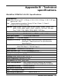
1
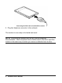
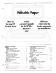
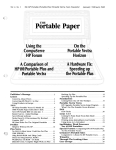
U.S. Robotics and the U.S. Robotics logo are U.S. Robotics registered trademarks. V.Fast Class (V.FC) is a Rockwell international registered trademark. Minitel and Télétel are France Telecom registered trademarks. IBM, IBM PC, PC/XT and PC/AT are International Business Machines Corporation trademarks. Microcom Networking Protocol (MNP) is a Microcom Inc. registered trademark. AutoSync is a Hayes registered trademark. Table of Contents CHAPTER 1- INSTALLATION 5 WorldPort PCMCIA V.34 CE Installation 5 CHAPTER 2 - USING THE MODEM 7 Installation Test Factory Settings Resetting the modem to the factory settings Remarks on using the modem 7 8 8 9 CHAPTER 3 - IN CASE OF PROBLEMS 11 Problems and Solutions If you are still having problems 11 13 APPENDIX A - TECHNICAL REFERENCE 15 Main AT commands Basic command set Extended command set S-Registers AutoSync 15 15 20 23 31 APPENDIX B - TECHNICAL SPECIFICATIONS 33 WorldPort PCMCIA V.34 CE Specifications Electrical Power Electro-magnetic Compatibility 33 34 34 GLOSSARY 33 Chapter 1- Installation WorldPort PCMCIA V.34 CE Installation Turn the computer and any connected peripheral devices off. 1. Locate the PCMCIA 2.0 compatible slot on the computer. Insert the modem in its slot with the side on which the product name is shown facing up. NOTE: an arrow on the top side of the card shows the proper direction to use for insertion. 2. The modem must be inserted deeply into the slot in order to connect it to the pins located at the back of the casing. Insertion of the WorldPort modem in the PCMCIA slot 3. Connect the DAA connector (telephone line interface) to the modem. Modem User’s Manual 5 Connecting the DAA cable to the WorldPort modem 4. Plug the telephone connector to the wall jack. The modem is now ready to be tested and used. NOTE: To remove the modem from its slot, see the computer documentation. Most computers have a button next to the slot to eject the modem in the same way as when you remove a diskette from its drive. 6 Modem User’s Manual Chapter 2 - Using the MODEM Installation Test Follow this procedure to check that the modem works correctly. 1. Turn the computer on. NOTE: Computers with PCMCIA ports have a program that initializes the PCMCIA port as a serial port when a modem is inserted in it. Check the computer documentation for further information. 2. Load and run the communications software. Check the software installation manual for further information. 3. In the software, set the serial port rate to 38.400 bits per second (bps) for a V.34 model (in some software, this is referred to as the 'baud rate’). The modem will automatically detect this setting when you send a command to it. 4. Specify the serial communications port used by the modem: COM1, COM2 or other. 5. Set the data format to an 8 bit length with no parity or to a 7 bit length with even or odd parity - either one will do - and 1 stop bit. 6. Execute the function that authorizes sending AT commands to the modem: in other words, put the computer in terminal mode. Verify that the computer and the modem can communicate with each other by sending the following ATtention command (you can type the command either with uppercase or lowercase letters, but you must not combine the two different types of letters). Press the Enter key (carriage return) , indicated in the following example by the word Enter surrounded by brackets. AT <Enter> If everything is OK, the modem will respond with the following message: OK NOTE: If the command is not echoed back (AT is not displayed on the screen), it means that local echo is turned off. In order to turn it on, send the following command to the modem. Modem User’s Manual 7 ATE1 <Enter> If, on the contrary, the screen displays double characters, it means that local echo is turned on both at the modem and in the software. Turn the software local echo off, if such an option is available, or turn the modem local echo off with the following command: ATE0 <Enter> Factory Settings The modem has been pre-configured at the factory. In most cases, it will work properly with these factory settings. But, if necessary, you can modify them with the communication commands: In order to display the present modem settings, do the following: Run the communications program. Go into the program's terminal mode. Type: AT &V <Enter>. The modem will respond to this command by displaying a list of the configuration settings. To modify them, please refer to Appendix A. Resetting the modem to the factory settings Some transmission sessions can modify the modem's configurations. If you are unsure of the current configuration of the modem or if it seems to be not working correctly, you might want to reset it to the factory settings. To do this: Run the communications program. Go into the program's terminal mode. Type: AT&F<Enter> This re-initialization includes resetting the hardware data control, setting a fixed speed on the communication port and complete result codes. On the other hand, some communications programs let you choose the modem in a menu list. If you can't find your modem there, you can enter this initialization string in the settings screen of the application. 8 Modem User’s Manual Remarks on using the modem Remember the following points when you use the modem: • The modem might not work with all modular telephone sets. Specifically, you must not use the modem with multi-line telephone sets, sets with indicator lights or line selection buttons. • Some voice mail message systems use a specific tone to indicate that a voice message has been received. The modem will not be able to dial as long as this signal is on the line. Listen to the waiting messages in order to get the normal dial tone back so that the modem can dial. • The modem has an automatic speed reduction function. This means that it automatically reduces its data transmission speed in order to match the speed of the remote modem. This also means that it may take the modem up to 30 seconds to establish communications with a slower modem. • A comma (,) in the dialed number causes a pause during dialing. You can insert multiple commas in the command line in order to obtain a longer pause. • The modem must detect a carrier within a specific time interval, otherwise it will display the message ‘NO CARRIER’ or ‘NO ANSWER’. You can increase this interval (in seconds) by going into the terminal mode of the communications application and typing in: AT S7 = [value]. Note: This value must be between 1 and 255 seconds (refer to the AT command table for further details). Modem User’s Manual 9 10 Modem User’s Manual Chapter 3 - In case of problems Problems and Solutions If you encounter problems even though you have followed the installation and use instructions of the modem, refer to the following table that lists the most common failures and their solutions. Identifying the current problem Symptom Solution The software indicates that the modem is not installed Check the software configuration. Make sure that it is configured for the appropriate COM port (in most cases it should be set to COM2). Check also that no other application is using this same port. Check also that the modem is properly inserted in its casing. The modem displays double characters on the terminal screen. Both the modem and the application local echoes are turned on. To turn local echo off type: The modem cannot make a call and sends the message ‘NO DIAL TONE’. Check the connection to the telephone line. It could be that the modem cannot detect the dial tone. Insert a comma (,) at the start of the dial sequence.. The modem does not respond when, in terminal mode, you send AT commands. Check that the COMmunications port to which the modem is connected is properly declared. Check the IRQ configuration in the communications software or in the Windows Control Panel. Check that the application is in terminal mode. ATE0 <Enter> If none of the preceding solutions solve the problem, it means that the modem is certainly in conflict at the COM port/IRQ level. Begin the installation procedure in the Installation chapter. Don't forget, if you change the COM/IRQ configuration, to also make these changes in the application. Modem User’s Manual 11 There is no audible tone when you try to call. The speaker is turned off; reset the modem's settings to the factory settings. The cables are not correctly connected. Check all connections from the telephone wall jack to the modem. There is a problem with the telephone line; check it using a standard telephone set. You are connected to an incompatible telephone network. Refer to the section: ‘Utilization Notes’ in this manual. The modem does not respond to incoming calls Check that the application's auto-answer mode is turned on. The modem connects to the remote modem, but the text received is illegible. Incorrect software configuration. Check that the transmission speed, the parity and the number of stop bits defined in the software correspond to the settings of the remote modem. Data compression could be used on one of the modems and not on the other. Check the flow control. If required, reconfigure the modem to the factory settings. Some office networks use a low voltage call signal that the modem cannot recognize. Try connecting the modem to a line that is not part of this type of network. The modem connects itself correctly to the remote modem, but the connection is interrupted during communications with the message: NO CARRIER. Someone probably hung up from another extension. Connection problem with a 2400 bps modem. Some older modem models will not connect when the error correction protocol is on. Turn this protocol off with the following command: The modem detected a call waiting signal on the line. Contact the local telecommunications agency to find out how to turn this signal off when you use the modem. Try calling another modem to check if the problem is general or unique to one specific modem. The telephone line is of low quality: try communicating at a lower speed. AT\N0 <Enter> High speed data transmission (V.32 bis, V.34) failed. 12 Check if there are any time-share applications or programs working in parallel to the communications application. The quality of the telephone line is too low to withstand high speed data transfer; decrease the modem's transmission speed. Modem User’s Manual International connections cannot be made.. Because of the length of the number dialed and the differences in telephone networks, it may be the case that some digits do not get interpreted during the dialing process. Insert commas between parts of the dialing number in order to create pauses. For example, if you are calling 0044628668476, insert commas and dial 00,44,628,668476 instead.. Calls to foreign countries terminate with a ‘NO CARRIER’ message. Increase the amount of time to wait for a carrier signal. In terminal mode, type ATS7=60 and press the Enter key. The wait period is then set to 60 seconds. Intercontinental connections are sometimes interrupted. If the telephone line's quality is low, it is best to reduce the transmission speed in order to insure that the connection remains stable. During file transfer, the modem sends back many transmission errors or a very low transfer rate. The telephone line is bad, select a lower transmission speed. During transmission of a fax errors alter its legibility or cut off the connection. Check the modem's and the software's flow control. Re-initialize the modem to the factory settings. Change the transfer protocol. Remove all terminate and stay resident programs (TSRs) that could be active during the connection. If the problem occurs during the transmission of a fax from Windows or OS/2 check that the communications driver that you are using is the one corresponding to the environment that you use (Windows, OS/2), or the one supplied specifically with the communications software. If you are still having problems • Re- read this manual, especially the 'Utilization notes'. • Contact your reseller who will be able to provide you with the necessary assistance. This is much more efficient and less costly than sending the modem back to us for a problem that is possibly only a simple matter of adjusting the settings. Modem User’s Manual 13 14 Modem User’s Manual Appendix A - Technical Reference Main AT commands 1. Type the commands entirely in upper case or lower case but do not type commands using a combination of the two cases. 2. All commands, with the exception of A/ and +++, are preceded by the AT prefix and are executed after pressing the Enter/ Carriage Return key (<Enter>). 3. The maximum length of a command is 40 characters. The modem does not count the AT prefix character, the Enter key or spaces. On the other hand, it does count punctuation marks such as dashes and parentheses. 4. Any missing numeric parameter is considered to be equal to zero, for instance the disconnect command: ATH <Enter>, is equivalent to ATH0 <Enter>. BASIC COMMAND SET Command Function AT ATtention: informs the modem that a command is being given to it. This prefix must precede all commands, except for A/, and +++. & Refer to the extended command set summary that follows this basic command set section. A Forces the answer/ auto-answer mode. The modem answers in answer mode when it detects a ring on the telephone line and it sends an answer tone. If it does not detect a carrier signal from a calling modem within 60 seconds, it goes off hook and the manual answer mode is canceled. Pressing any key after the modem answers, cancels manual answer and causes the modem to go on hook. A/ Re-executes the last command once. A/ does not require the AT prefix nor the Enter key. Modem User’s Manual 15 Bn CCITT or BELL B0 V.22 status, 1200 bps connection or V.21 connection at 300 bps. B1 Bell 212A status, connection at 1200 bps or Bell 103 connection at 300 bps. Dn Dialing DL Re-dial the last number DP Pulse (rotary) dial DT Tone dial (DTMF) DS=n Dial the stored number ! Flash: Rapid on hook W Wait for tone before dialing @ Wait for a quiet answer , Pause during dialing ; Return to command mode En Command Echo E0 Turns echo off E1 Turns echo on Fn Selecting modulation speed F0 Auto detect mode (equivalent to N1) F1 V.21 or Bell 103 indication F2 Reserved F3 V.23 indication F4 V.22 or Bell 212A status: 1200 bps speed F5 V.22 bis status: 2400 bps speed F6 V.32 bis or V.32 status: 4800 bps F7 V.32 bis status: 7200 bps F8 V.32 bis or V.32 status: 9600 bps F9 V.32 bis status: 12.000 bps F10 V.32 bis status: 14.400 bps Hn Disconnect (on/off hook) H0 On hook H1 If already on hook, goes off hook and into command mode In Identification codes I0 Product code I1 ROM checksum I2 Checksum and status I3 Firmware version number I4 Specific information I5 Returns the country code 16 Modem User’s Manual I6 Returns the Data pump model Modem User’s Manual 17 Ln Speaker level control L0 Low volume L1 Low volume L2 Medium volume L3 High volume Mn Speaker control M0 Turns the speaker off M1 Speaker active until connection M2 Speaker always active (during dialing and connection) M3 Speaker inactive during dialing but active during connection Nn Automode control N0 Turns automatic speed detection off N1 Turns automatic speed detection on On Return on-line (from command mode) O0 Return to data transmission mode O1 Return to data transmission mode with resync request P Forces pulse dialing Qn Control codes display Q0 Displays DTE code results Q1 Inhibits DTE code results Sn Read/Write to the S register Sn Selects the n register as the default register Sn=v Sets register n to v Sn? Returns the value contained in register n T Forces tone dialing (DTMF). Vn Result code format V0 Abbreviated format V1 Long format Wn Connection control message W0 Returns the DTE speed W1 Returns the line speed, data correction protocol and DTE speed W2 Returns DCE speed 18 Modem User’s Manual Xn Extended result codes X0 Displays the basic status messages of the call, ex: OK, CONNECT, RING, NO CARRIER, NO ANSWER and ERROR X1 Displays the basic status messages of the call and connection speeds (OK, CONNECT, RING, NO CARRIER, NO ANSWER, CONNECT XXXX, and ERROR. X2 Displays the basic status messages of the call and connection speeds(OK, CONNECT, RING, NO CARRIER, NO ANSWER, CONNECT XXXX, and ERROR. X3 Displays the basic status messages of the call and transmission rates (OK, CONNECT, RING, NO CARRIER, NO ANSWER, CONNECT XXXX, and ERROR. X4 Displays all status messages of the call and connection speeds Yn On hook upon reception of a long break Y0 Deactivates on hook upon reception of a long break Y1 Activates on hook upon reception of a long break Zn Software re-initialization and reset of the configuration Z0 Re-initialization and reset of settings stored in profile 0 Z1 Re-initialization and reset of settings stored in profile 1 +MS=<mod>, [<automod>, <mini>, <maxi>]. Selection of modulation speed <mod> specifies modulation (0,1,2,3,9,10,11, 64,69, 74). <automod> Negotiation of forced or automatic modulation (0 or 1). <mini> specifies the minimum speed that the modem will connect at (according to the modulations given below). <maxi> specifies the maximum speed at which the modem will connect at. Example: AT+MS=11,1,14.400,28.800 +MS? Returns the modem's current settings +MS=? Returns the list of values accepted by the modem +MS=0 V.21 indication +MS=1 V.22 status: 1200 bps speed +MS=2 V.22 bis status: 1200 or 2400 bps speed +MS=3 V.23 status: E/R at 75/1200. Answer: E/R at 1200/75. Always specify the speed at 1200 bps. +MS=9 V.32 status: 9600 bps or 4800 bps +MS=10 V.32 bis status: 14.400, 12.000, 9600, 7200 or 4800 bps +MS=11 V34 status: 28.800, 26.400, 24.000, 21.600, 19.200, 16.800, 14.400, 12.000, 9600, 7200, 4800 or 2400 bps +MS=64 Bell status 103 at 300 bps Modem User’s Manual 19 +MS=69 Bell status 212 at 1200 +MS=74 V.FC status at 28.800, 26.400, 24.000, 21.600, 19.200, 16.800 or 14.400 bps EXTENDED COMMAND SET \An MNP Block size \A0 Configures MNP maximum block size to 64 \A1 Configures MNP maximum block size to 128 \A2 Configures MNP maximum block size to 192 \A3 Configures MNP maximum block size to 256 \Bn Transmits break signals n times 100 ms.(from 1 to 9) \Gn Enables/disables the modem to modem flow control (XON/XOFF) \G0 Disables flow control between modems \G1 Enables flow control between modems \Kn Types of Break to send to the modem \Ln MNP transfer mode \L0 MNP stream mode \L1 MNP block mode \Nn Mode selection \N0 Selects normal speed, buffer mode \N1 Selects direct mode \N2 Selects error correction mode: Goes on hook in case of failure \N3 Selects error correction mode: Switches to buffer mode in case of failure \N4 Forces LAPM mode \N5 Forces MNP mode &Cn RLSD (DCD) Option &C0 Forces the DCD signal to 'ON' &C1 True DCD according to the carrier detect signal &Dn DTR Option &D0 DTR signal override &D1 Returns to command mode on falling edge of DTR &D2 Returns to command mode and goes on hook on falling edge of DTR &D3 Re-initializes the modem and loads the configuration profile indicated by the &Y command 20 Modem User’s Manual &Fn Load the factory settings &F0 Load factory configuration profile 0 &F1 Load factory configuration profile 1 Modem User’s Manual 21 &Gn Set the guard tone &G0 Turns the guard tone off &G1 Turns the guard tone off &G2 Sets the guard tone to 1800 Hz. &Jn Telephone plug control &J0 Sets bit 1 of the S21 register to be &J1 compatible with the Hayes command set &Kn Flow control &K0 Turns flow control off &K3 Turns RTS/CTS flow control on &K4 Turns XON/XOFF flow control on &K5 Transparent flow control XON/XOFF DTE/DCE. &K6 Turns RTS/CTS and XON/XOFF flow controls on &Pn Select pulse (rotary) dial make/break ratio &P0 10 ips with 39%/61% ratio &P1 10 ips with 33%/67% ratio &P2 20 ips with 39%/61% ratio &P3 20 ips with 33%/67% ratio &Qn Synchronous/Asynchronous modes &Q0 Select direct asynchronous mode &Q4 Select AutoSync mode &Q5 The modem negotiates a connection with error control &Q6 Select asynchronous operation in normal mode &Rn RTS / CTS option &R0 CTS follows RTS &R1 CTS is always active &Sn DSR management &S0 DSR is always active &S1 True DSR. &Vn Displays the current configuration &V Displays the current configuration profile &Wn Store the current configuration &W0 Store the current profile in NVRAM as profile 0 &W1 Store the current profile in NVRAM as profile 1 &Yn Specifies the default re-initialization configuration profile &Y0 Upon power up the configuration is set to profile 0 &Y1 Upon power up the configuration is set to profile 0 22 Modem User’s Manual &Zn=x Stores the dial string x (35 char.) in position n (0 to 4). %Cn Turns data compression on/off %C0 Turns data compression off %C1 Sets data compression to MNP 5 %C2 Sets data compression to V.42 bis %C3 Sets data compression to both V.42 bis and MNP 5. S Registers Default values are appropriate for most users. The settings are modified with the ATSr=n command, where r is the number of the S register and n is a decimal value between 0 and 255 (unless otherwise stated). Use ATSr? To examine the configuration of a register. For example: ATS0? Enter Reg Default S0 2 Sets the number of rings on which to answer in Auto Answer Mode When set to 0, Auto Answer is disabled. Accepted values are 0 or 2. S1 0 Counts and stores the number of rings from an incoming call. The range of acceptable values is from 0 to 255. S2 43 Stores the ASCII decimal code for the escape code character. The default character is '+'. A value between 128 and 255 disables the escape code. The range of acceptable values is from 0 to 255. S3 13 Stores the ASCII decimal code for the carriage return character. The range of acceptable values is from 0 to 127. S4 10 Stores the ASCII decimal code for the new line character. The range of acceptable values is from 0 to 127. S5 8 Stores the ASCII decimal code for the back space character. The range of acceptable values is from to 32. 0 Function Modem User’s Manual 23 Reg Default S6 8 Sets the number of seconds the modem waits before dialing. If it is set to X2 or X4, the modem ignores this register and dials as soon as it detects a dial tone (fast dials). The range of acceptable values is from 6 to 12. S7 55 Sets the number of seconds the modem waits for a carrier. May be set for a much longer duration if, for example, the modem is making an international connection. The range of acceptable values is from 36 to 58. S8 option 2 Sets the duration, in seconds, for the pause (,) in the Dial command. The range of acceptable values is from 0 to 255. S9 6 Sets the required duration, in tenths of a second, of the remote modem’s carrier signal before by the modem. The range of acceptable values is from 0 to 255. S10 14 during loss the other momentarily remote Sets the required delay, in tenths of a second, which the modem waits before hanging up after of the carrier signal. This guard delay is used by modem to differentiate between interference or disturbance that interrupts a connection and the disconnection (going on hook ) of the modem. This waiting interval is set to the value of S10 minus the value of S9. In any event S10 must be greater than S9 or the modem will disconnect before recognizing the carrier signal. NOTE: If you set S10 = 255, the modem will not hang up if the carrier signal is lost. Removal of the DTR signal will force the modem to hang up. recognition S11 Function 95 Sets the duration and spacing, in milliseconds, for tone dialing. The range of acceptable values is 0 to 255. S12 50 Sets the duration, in fiftieths of a second, of the guard time for the escape code sequence (+++). S13 - from 24 Reserved Modem User’s Manual Reg Default Function S14 170 S15 - Reserved S16 0 Bit-mapped register: see the instructions for register S14. Bit-mapped register. Select the bits that should be set to one and set S14 to the decimal total of the found binary value. For example, if you want to set bits 7 (value = 128) and 5 (value = 32), the S14 register should be set to 160 decimal. In the same way ATS14=17 set bit 0 (value = 1) and bit 4 (value = 16). 1 Echo command (Er - 0 = E0, 1 = E1) 2 Quiet mode (Qr - 0 = Q0, 1 = Q1) 3 Result codes (Vr - 0 = V0, 1 = V1) 4 Reserved 5 Tone (T)/Pulse (P) (0 =T, 1 = P) 6 Reserved 7 Send/Answer (0 = Answer, 1 = Send Bit 0 1 2 3 4-6 Val 2 4 8 - Result Reserved Dialing test Specifications test Remote digital loopback Reserved S17 - Reserved S18 0 Sets the duration of attempts, in seconds, before the modem returns to command mode. If the value is set to 0, the test will not terminate automatically. It will have to be stopped using the &T0 or H command. S19 0 AutoSync S20 0 AutoSync Modem User’s Manual 25 Reg Default S21 4 Function V.24 Bit 0 Val 0 1 2 1 3-4 0 5 0 6 0 7 0 2=&D2, Result Depends on the &J0. 1=&J1 command Reserved Equivalent to &R1 CTS always on. 0=&R0 CTS follows RTS. Equivalent to &D0. 1=&D1, 3=&D3 Equivalent to &C0, for what concerns the DCD. 1=&c1 Equivalent to &S0, for what concerns the DSR. 1=&S1 Equivalent to Y0. 1=Y1 S22 117 Speaker and results code Bit Val Result 0-1 1 Equivalent to L1. 0 = Low, 2 = Medium, 3 = High 2-3 1 Equivalent to M1. 0 = Off, 2 = always active, 3+ = Active during handshaking period 4-6 7 Equivalent to X4. 0=X0, 4=X1, 5=X2, 6=X3 7 Reserved S23 54 General Bit Val 0 0 1-3 3 4-5 3 6-7 0 S24 26 0 Result RDL not allowed DTE speed set to 2400 bps Default DTE parity Equivalent to &G0. Sets, in seconds, the duration of operation of the modem, in normal mode, with no activity on the line before going into sleep mode. The timer is reinitialized as soon as there is any activity on the line. If S24 is set to 0, the sleep mode is disabled. Modem User’s Manual Reg Default Function S25 5 Sets, in hundredths of second, the duration in which the DTR signal must be off for the modem not to interpret a random problem as a loss of the DTR signal. (Most users will use the default value; this register is useful to insure compatibility with older models that use older operating software.) S26 1 Reserved S27 9 S28 0 Select asynchronous/synchronous mode Bit Val Result 0,1,3 5 Equivalent to &Q5. 0=&Q0, 1=&Q1, 2=&Q2. 3=&Q3, 4=&Q4, 6=&Q6. 2 0 Reserved 4,5 0 Reserved 6 0 Equivalent to B0. 1=B1. 7 Reserved Bit 0-2 3-4 Val 0 5 6-7 0 2=&P2, Result Reserved Equivalent to &P0. 1=&P1, 3=&P3 Reserved Equivalent to *H0. 1=*H1, 2=*H2. S29 0 Duration of the inactive period after a flash Sets the duration, in tenths of a second, before the modem hangs up after a Flash. From 0 to 255 in 10 ms intervals. S30 0 Sets the duration, in tenths of a second for the timer to be inactive. The timer is activated when there is no activity on the telephone line. At the end of this period the modem goes on hook (hangs up). If S30=0 the timer is disabled. S31 2 Reserved S32 17 S33 19 Stores the decimal ASCII code of the XON character. Stores the decimal ASCII code of the XON character. Modem User’s Manual 27 Reg Default S34 S35 S36 7 Reserved Reserved LAPM mode error control. Answer failure in LAPM. The value indicates what will happen in case of failure. Bit Value Result 0-2 7 0 = On hook, 1 = Stays on line and toggles to direct mode, 2 = Reserved, 3 = Stays on line and toggles to standard mode, 4 = Attempt to make an MNP connection, go on hook in case of failure, 5 = Attempt to make an MNP connection, in case of failure, toggles to direct mode, 6 = Reserved, 7 = Attempt to make an MNP connection, in case of failure, toggles to normal mode. 3-7 Reserved S37 0 Connection line speed. Identical to the 'F' or '+MS' commands. 0 Attempt to connect at the maximum speed (F0) 1-3 Attempt to connect at 300 bps (+MS=0 or F1) 4 Reserved 5 Attempt to connect at 1200 bps (+MS=1 or F4) 6 Attempt to connect at 2400 bps (+MS=2 or F5) 7 Attempt to connect in V.23 (+MS=3 or F3) 8 Attempt to connect at 4800 bps (+MS=9,1,,4800 or F6) 9 Attempt to connect at 9600 bps (+MS=9,1,,9600 or F8) 10 Attempt to connect at 12.000 bps (+MS=10,1,,12000 or F9) 28 Function Modem User’s Manual Reg Default Function 11 Attempt to connect at 14.400 bps (+MS=10,1,,14.400 or F10) Attempt to connect at 7200 bps (+MS=11,1,,7200 or F7) 12 S38 S39 20 Sets, in seconds, an optional delay, before forcing disconnection and erasing the transmission buffer when the DTR signal is removed during a call with error control. This allows a remote modem to acknowledge reception of all data before being disconnected. The default value is set to 0: the modem goes on hook immediately when the DTR signal falls. 3 Flow control Bit Value 0-2 3 3-7 S40 105 S41 131 - Result RTS/CTS Equivalent to &K3. 0 = No checking 4=&K4, 5=&K5, 6=&K6. Reserved Extended MNP functions 0-1 0 Disables the extended functions, Equivalent to -K0. 1=-K1, 2=-K2. 2 0 Level setting 3-5 5 Equivalent to \K5. 0=\K0, 1=\K1, 2=\K2,3=\K3, 4=\K4. 6-7 1 MNP block size, Equivalent to \A1. 0=A0, 2=\A2, 3=\A3. 0-1 3 2 and 6 3 4 5 7 0 1 Equivalent to %C3. 0=%C0, 1=%C1, 2=%C2 Equivalent to %E0. 2=%E1, 64=%E2. Reserved Equivalent to \L0. 1=\L1 Reserved Equivalent to -Q1. 0=-Q0. Modem User’s Manual 29 Reg Default S46 138 S48 7 V.42 Protocol 0 = Deactivates the V.42 handshaking and proceeds directly with the LAPM protocol 7 = Enables V.42 handshaking. 128 = Disables handshaking and detection and takes into account the S36 register (can be used to force an MNP connection). S80 - Reserved S82 - Break management. This register exists only for compatibility reasons. Modifying this register will have no effect. S86 - Result code on call failure reasons 0 = Normal disconnect 4 = Carrier loss 5 = Handshaking failure during connection with the remote modem 9 = No common protocols 12 = Normal disconnect initiated by the remote modem 13 = No answer after 10 re-transmissions of the same message 13 = Protocol violation S91-S92 30 Function Data compression 136 = Error control without compression 138 = Error control with compression Reserved Modem User’s Manual Reg Default S95 Function 44 Bit 0 Value 1 1 2 2 3 4 8 4 5 16 32 6 7 64 128 S99 - Reserved S202 - Reserved Result CONNECT indicates the DCE speed Adds ARQ to CONNECT in error control mode Enables display of CARRIER xxxx Enables display of PROTOCOL xxxx Reserved Enables display of COMPRESSION xxxx Reserved Reserved AutoSync Modems are traditionally divided into two categories: • asynchronous modems that communicate with the PC via an asynchronous coupler called UART, • synchronous modems, interfaced with an asynchronous coupler (SCC, USART, etc.). The function of the couplers mentioned above is to transform, on a computer, the 'parallel' data on 8 wires, byte by byte, into a flow of 'serial' data composed of bits following each other on one wire. According to whether the coupler is synchronous or asynchronous, the parallel to serial conversion is performed in a different manner. For this reason, a synchronous modem cannot interpret the data coming from a remote asynchronous modem. The function of AutoSync is to allow an asynchronous modem to dialog with a synchronous modem by reconverting the asynchronous/synchronous data coming from a PC. AutoSync provides synchronous transmissions via the asynchronous port of the modem. Synchronous transmissions can be in bit mode (HDLC, SDLC) or in character mode (VIP, etc.). Modem User’s Manual 31 32 Modem User’s Manual Appendix B - Technical specifications WorldPort PCMCIA V.34 CE Specifications Compatibility Data: ITU-T V.34, V.FC, V.32 bis, V.32, V.23, V.22 bis, V.22, V.21 and Bell 212A ,103. Fax: Transmission/reception Group III Fax, Class 1, Class 2; ITU-T V.17, V.29, V.27 ter Speeds: Data: 28.8K, 26.4K, 24K, 21.6K, 19.2K, 16.8K, 14.4K, 12K, 9600, 7200, 4800, 2400, 1200, 1200/75, 75/1200, 300 bps Fax: 14.4K, 12K, 9600, 7200, 4800, 2400 bps Error correction ITU-T V.42, MNP 2-4 Data compression ITU-T V.42 bis, MNP level 5 and 10 Serial port speed 115.200 bps maximum Operation Full/Half duplex Format (DTE-DCE) Serial, binary, asynchronous, synchronous, AutoSync Hayes protocol for synchronous transmissions Command set Compatible with the AT command set; Fax mode: EIA 578 Class 1, TR 29 Class 2 Flow control XON/XOFF, RTS/CTS Data interface Bus, 16.550 compatible (FIFO) Connector 68-pin compatible PCMCIA 2.0-2.1 Telephone interface RJ11 Dialing Pulse, tone (DTMF 0-9, #, *) Audio capability Speaker on host Call status Dial tone, busy tone Store configuration Non volatile memory storing two modem configurations and four telephone numbers Transmission level Country specific Reception sensitivity Country specific Size 54 x 85,6 x 5 mm Operating temperature from 0 to 50 °C Modem User’s Manual 33 Storage temperature from -40 to +70 °C Transportation temperature from -40 to +70 °C Operating humidity from 20 to 80% without condensation Storage humidity from 5 to 90% without condensation Operating altitude 3000 meters Electrical Power Before making connections, check the safety levels on the various interfaces: Telephone line connector = TRT PCMCIA 2.0 connector = TBTS These indications are classified as per security standard EN 60-950/A2 dated October 1993. TBTS: Very Low Safety Voltage TRT: Telecommunications Network Voltage, voltages in compliance with standard NF EN 41-003 dated July 1993 criteria. Electro-magnetic Compatibility This device complies with the following standards in accordance with the European Directives 91/263/CEE and 89/336/CEE: - Immunity EN50082-1 class B - Transmission EN 55022 34 Modem User’s Manual Glossary ARQ General term qualifying error correction protocols that detect errors and automatically re-transmit the incorrect data blocks. See MNP and V.42. ASCII Acronym for American Standard Code for Information Interchange. 7 bit binary code (0 and 1) used to represent letters, numbers and special characters such as $,! and /. Bit A 0 or a 1 reflecting the use of a binary numbering system (a system that consists of 2 values). This system is used because the computer only recognizes two states, off or on. (Start/Stop bits) Signaling bits attached to a character before it is transmitted; used for asynchronous transmissions. Bps The rate in bits per second. Thousands of bits per second are expressed as kilobits. Cps Data transfer rate (Characters per second). It is generally estimated from the binary rate and the length of characters. For example, at 2400 bits/s, 8-bit characters with a start and stop bit (for a total of 10 bits per character) are transmitted at an approximate rate of 240 characters per second (cps). Some protocols, such as the error correction protocols in the modem use advanced techniques requiring longer transmission frames and data compression to increase the number of characters per second. Flow control A method that compensates for differences in the data flow coming in to and going out from a modem or other device. See RTS/CTS and XON/XOFF Error correction Various techniques that check the reliability of the characters or data blocks. The V.42 and MNP2-2, 10 error correction protocols use error detection (using a CRC type control code) and re-transmit erroneous frames (ARQ). Modem User’s Manual 35 DCE (Data Carrier Equipment) Termination equipment of the data circuit. In this manual, this term applies to modems that establish and control the data link on the telephone network. Transmission rate Number of bits transmitted per second (bit/s). Communications channels using modems on telephone lines are set to binary rates, generally 2400, 9600, 14.400 or 28.800. Baud rate Number of state transitions per second on a communications channel. Even though it is incorrect from a strict technical point of view, the baud rate is often used to indicate the transmission rate. DTE (Data Terminal Equipment) Data processing terminal equipment. Generally, a computer or terminal generates data or is the final destination of data. Duplex Defines a communications channel capable of transmitting signals in both directions (half duplex or full duplex). Full duplex: Simultaneous flow of signals in two directions. In microcomputer communications, full duplex can refer to suppressing the local echo of transmitted characters.. Half Duplex: Signal flow in two directions, but only in one at a given time. In micro-computer communications, half duplex can refer to enabling of the local echo that causes the modem or the software to send a copy of transmitted data to the screen of the transmitting computer. Remote Echo A copy of the data received by the remote system is sent back to the transmitting system and displayed on the screen. Remote echo is a function of the remote system and is often used in full duplex transmissions. Local Echo A function of the modem used to display keyboard command and transmitted data on the screen. This function is provided with most communications software. 36 Modem User’s Manual IRQ Interrupt Request. In a computer, IRQs are used to temporarily interrupt current processing when an event requires immediate attention, such as for example, the arrival of data at the serial port. LAPM Link Access Procedure for Modems. Error correction protocol incorporated in the ITU-T V.42 recommendation. Just like the MNP protocols, LAPM uses cyclical redundancy check (CRC) and automatic re-transmission of data (ARQ) to guarantee data reliability. NVRAM Non Volatile Random Access Memory which can be programmed by the user with data that are stored when the modem is powered down. The modem includes this kind of memory to store a default configuration defined by the user and loaded into random access memory (RAM) upon power up. MNP Microcom Networking Protocol. Error correction protocol developed by Microcom, Inc. and now in the public domain. MNP protocol guarantees error-free transmissions using error detection (CRC) and re-transmission of incorrect data frames. The modem uses MNP 2-4 and MNP 5 error correction and data compression techniques that are incorporated in recommendation ITU-T V.42. Data mode Mode in which the fax/modem can send and receive data files. A standard modem without facsimile capabilities is always in data mode. Fax mode Mode in which the fax/modem can transmit and receive facsimiles. Terminal mode Required simulation mode for computers to transmit data. In terminal mode, the computer acts as though it were a dumb terminal rather than a data processing unit. Keystrokes go directly to the modem whether they are modem commands or data to be transmitted via the telephone lines. Received data are displayed directly on the screen. Modem User’s Manual 37 Parity Error detection method that checks the correctness of transmitted characters. Verification of characters has been replaced by more reliable and efficient block control methods, including Xmodem types of protocols and the ARQ protocol implemented in the modem. Two communicating computers must use the same kind of parity. Carrier Continuous frequency that can be modulated or act as a support to another data carrier signal. Carrier waves are generated and maintained by modems via the telephone companies' transmission lines. Protocol Set of rules and procedures describing communications between different devices. Protocols vary, but communications equipment must use the same protocol in order to exchange data. Data formats, the ready to receive or transmit states, error detection and correction are some of the operations that can be defined in protocols. Fallback (Rate adjustment). A function that lets rapid modems with error correction control the line quality and fall back to a lower speed if it becomes degraded. Modems go back to a higher speed if the line quality improves. RTS/CTS Hardware check used to tell an intelligent device to stop or resume data transmission. Analog signals Variable and continuous waves, such as voice tones carried by telephone lines. Compare with digital signals. Digital signals Discrete and uniform signals. In this manual, the term refers to bits 0 and 1. Buffer An area of memory used as temporary storage during input/output operations. The modem has, for example, a command buffer. 38 Modem User’s Manual Terminal A unit whose keyboard and screen are used to send and receive data via a communications link. A terminal differs from a micro-computer in that it has very little or no internal processing capabilities. Asynchronous transmission Data transmission during which the time between transmission of characters can vary. Since the time delays between characters are not uniform, the receiving modem must be signaled when the start and end of a characters data bits occur. Stop and start bits are therefore added to each character transmitted. Serial transmission Sequential data transfer, one bit at a time, using only one electrical circuit. Synchronous transmission Data transmission during which both communicating devices are synchronized by a common clock. Using this mode eliminates the need to systematically add a stop bit and a start bit to each transmitted character. Xmodem The first of a family of error correction software protocols used to transfer files between modems. These protocols are in the public domain and are available on many servers. Ymodem and Zmodem are later protocols. XON/XOFF Standard ASCII control characters used to tell an intelligent device to stop or resume data transmission. In most systems, typing <Ctrl>-S sends the XOFF character (which tells the remote device to stop transmitting). Some equipment, including your modem, interpret <Ctrl>Q as XON (which tells the remote device to resume transmission), others interpret touching any key after <Ctrl>-S as an XON. Modem User’s Manual 39