1
May 2003
Process Control Instruments
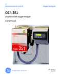
Model TMO2D-TC
Thermal Conductivity Analyzer
User’s Manual
910-146A2
May 2003
TMO2-TC Thermal Conductivity Transmitter with TMO2D
iii
May 2003
Warranty
Each instrument manufactured by GE Panametrics is warranted to be
free from defects in material and workmanship. Liability under this
warranty is limited to restoring the instrument to normal operation or
replacing the instrument, at the sole discretion of GE Panametrics. Fuses
and batteries are specifically excluded from any liability. This warranty
is effective from the date of delivery to the original purchaser. If GE
Panametrics determines that the equipment was defective, the warranty
period is:
•
one year for general electronic failures of the instrument
•
one year for mechanical failures of the transducers
If GE Panametrics determines that the equipment was damaged by
misuse, improper installation, the use of unauthorized replacement parts,
or operating conditions outside the guidelines specified by GE
Panametrics, the repairs are not covered under this warranty.
The warranties set forth herein are exclusive and are in lieu of
all other warranties whether statutory, express or implied
(including warranties or merchantability and fitness for a
particular purpose, and warranties arising from course of
dealing or usage or trade).
Return Policy
If a GE Panametrics instrument malfunctions within the warranty period,
the following procedure must be completed:
1. Notify GE Panametrics, giving full details of the problem, and
provide the model number and serial number of the instrument. If the
nature of the problem indicates the need for factory service, GE
Panametrics will issue a RETURN AUTHORIZATION NUMBER
(RAN), and shipping instructions for the return of the instrument to a
service center will be provided.
2. If GE Panametrics instructs you to send your instrument to a service
center, it must be shipped prepaid to the authorized repair station
indicated in the shipping instructions.
3. Upon receipt, GE Panametrics will evaluate the instrument to
determine the cause of the malfunction.
Then, one of the following courses of action will then be taken:
iv
•
If the damage is covered under the terms of the warranty, the
instrument will be repaired at no cost to the owner and returned.
•
If GE Panametrics determines that the damage is not covered under
the terms of the warranty, or if the warranty has expired, an estimate
for the cost of the repairs at standard rates will be provided. Upon
receipt of the owner’s approval to proceed, the instrument will be
repaired and returned.
May 2003
Table of Contents
Chapter 1: Features and Capabilities
Overview . . . . . . . . . . . . . . . . . . . . . . . . . . . . . . . . . . . . . . . . . . . . . . . . . . . . . . . . . . . . . . . . . . . .1-1
Introduction . . . . . . . . . . . . . . . . . . . . . . . . . . . . . . . . . . . . . . . . . . . . . . . . . . . . . . . . . . . . . . . . . .1-1
Theory of Operation . . . . . . . . . . . . . . . . . . . . . . . . . . . . . . . . . . . . . . . . . . . . . . . . . . . . . . . . . . .1-3
System Description . . . . . . . . . . . . . . . . . . . . . . . . . . . . . . . . . . . . . . . . . . . . . . . . . . . . . . . . . . . .1-5
TMO2-TC Transmitter . . . . . . . . . . . . . . . . . . . . . . . . . . . . . . . . . . . . . . . . . . . . . . . . . . . . . .1-5
Sample System . . . . . . . . . . . . . . . . . . . . . . . . . . . . . . . . . . . . . . . . . . . . . . . . . . . . . . . . . . . .1-9
TMO2D-TC Display . . . . . . . . . . . . . . . . . . . . . . . . . . . . . . . . . . . . . . . . . . . . . . . . . . . . . . . .1-9
Extra Cable (optional). . . . . . . . . . . . . . . . . . . . . . . . . . . . . . . . . . . . . . . . . . . . . . . . . . . . . . .1-9
Typical Applications . . . . . . . . . . . . . . . . . . . . . . . . . . . . . . . . . . . . . . . . . . . . . . . . . . . . . . . . . .1-10
Chapter 2: Installation
Overview . . . . . . . . . . . . . . . . . . . . . . . . . . . . . . . . . . . . . . . . . . . . . . . . . . . . . . . . . . . . . . . . . . . .2-1
Introduction . . . . . . . . . . . . . . . . . . . . . . . . . . . . . . . . . . . . . . . . . . . . . . . . . . . . . . . . . . . . . . . . . .2-2
Mounting the TMO2-TC Transmitter . . . . . . . . . . . . . . . . . . . . . . . . . . . . . . . . . . . . . . . . . . . . . .2-2
Mounting the Sample System . . . . . . . . . . . . . . . . . . . . . . . . . . . . . . . . . . . . . . . . . . . . . . . . . . . .2-3
Manual, 2-Port (Sealed Reference Gas) Sample System . . . . . . . . . . . . . . . . . . . . . . . . . . . .2-3
Manual, 4-Port (Flowing Reference Gas) Sample System . . . . . . . . . . . . . . . . . . . . . . . . . . .2-4
Automatic, 2-Port (Sealed Reference Gas) Sample System . . . . . . . . . . . . . . . . . . . . . . . . . .2-5
Mounting the TMO2D-TC Display. . . . . . . . . . . . . . . . . . . . . . . . . . . . . . . . . . . . . . . . . . . . . . . .2-6
Wiring the TMO2-TC Transmitter . . . . . . . . . . . . . . . . . . . . . . . . . . . . . . . . . . . . . . . . . . . . . . . .2-7
Wiring the TMO2D-TC Display . . . . . . . . . . . . . . . . . . . . . . . . . . . . . . . . . . . . . . . . . . . . . . . . .2-12
Chapter 3: Operation
Overview . . . . . . . . . . . . . . . . . . . . . . . . . . . . . . . . . . . . . . . . . . . . . . . . . . . . . . . . . . . . . . . . . . . .3-1
Introduction . . . . . . . . . . . . . . . . . . . . . . . . . . . . . . . . . . . . . . . . . . . . . . . . . . . . . . . . . . . . . . . . . .3-1
Powering Up the TMO2D-TC Analyzer . . . . . . . . . . . . . . . . . . . . . . . . . . . . . . . . . . . . . . . . . . . .3-1
Establishing a Flow of Sample Gas. . . . . . . . . . . . . . . . . . . . . . . . . . . . . . . . . . . . . . . . . . . . . . . .3-2
Operating the TMO2D-TC Display. . . . . . . . . . . . . . . . . . . . . . . . . . . . . . . . . . . . . . . . . . . . . . . .3-3
LCD Display . . . . . . . . . . . . . . . . . . . . . . . . . . . . . . . . . . . . . . . . . . . . . . . . . . . . . . . . . . . . . .3-3
Keypad . . . . . . . . . . . . . . . . . . . . . . . . . . . . . . . . . . . . . . . . . . . . . . . . . . . . . . . . . . . . . . . . . .3-3
Chapter 4: Programming
Overview . . . . . . . . . . . . . . . . . . . . . . . . . . . . . . . . . . . . . . . . . . . . . . . . . . . . . . . . . . . . . . . . . . . .4-1
Introduction . . . . . . . . . . . . . . . . . . . . . . . . . . . . . . . . . . . . . . . . . . . . . . . . . . . . . . . . . . . . . . . . . .4-2
Key Functions . . . . . . . . . . . . . . . . . . . . . . . . . . . . . . . . . . . . . . . . . . . . . . . . . . . . . . . . . . . . . . . .4-3
Entering Programming Mode . . . . . . . . . . . . . . . . . . . . . . . . . . . . . . . . . . . . . . . . . . . . . . . . . . . .4-5
Menu Navigation . . . . . . . . . . . . . . . . . . . . . . . . . . . . . . . . . . . . . . . . . . . . . . . . . . . . . . . . . . . . . .4-5
The Main Menu . . . . . . . . . . . . . . . . . . . . . . . . . . . . . . . . . . . . . . . . . . . . . . . . . . . . . . . . . . . . . . .4-6
The Setup Menu . . . . . . . . . . . . . . . . . . . . . . . . . . . . . . . . . . . . . . . . . . . . . . . . . . . . . . . . . . .4-6
The Recorders Menu. . . . . . . . . . . . . . . . . . . . . . . . . . . . . . . . . . . . . . . . . . . . . . . . . . . . . . .4-13
The Alarms Menu . . . . . . . . . . . . . . . . . . . . . . . . . . . . . . . . . . . . . . . . . . . . . . . . . . . . . . . . .4-15
The Tests Menu. . . . . . . . . . . . . . . . . . . . . . . . . . . . . . . . . . . . . . . . . . . . . . . . . . . . . . . . . . .4-16
The Calibration Menu . . . . . . . . . . . . . . . . . . . . . . . . . . . . . . . . . . . . . . . . . . . . . . . . . . . . . .4-19
v
May 2003
Table of Contents (cont.)
Chapter 5: Calibration
Overview . . . . . . . . . . . . . . . . . . . . . . . . . . . . . . . . . . . . . . . . . . . . . . . . . . . . . . . . . . . . . . . . . . .
Introduction . . . . . . . . . . . . . . . . . . . . . . . . . . . . . . . . . . . . . . . . . . . . . . . . . . . . . . . . . . . . . . . . .
Required Equipment and Materials . . . . . . . . . . . . . . . . . . . . . . . . . . . . . . . . . . . . . . . . . . . . . . .
Preparing the Transmitter for Calibration . . . . . . . . . . . . . . . . . . . . . . . . . . . . . . . . . . . . . . . . . .
2-Port (Sealed Reference Gas) Calibration . . . . . . . . . . . . . . . . . . . . . . . . . . . . . . . . . . . . . . . . .
4-Port (Flowing Reference Gas) Calibration . . . . . . . . . . . . . . . . . . . . . . . . . . . . . . . . . . . . . . . .
Checking/Changing Switch and Jumper Settings . . . . . . . . . . . . . . . . . . . . . . . . . . . . . . . . . . . .
5-1
5-1
5-3
5-4
5-6
5-8
5-9
Chapter 6: Specifications
TMO2-TC Transmitter Specifications . . . . . . . . . . . . . . . . . . . . . . . . . . . . . . . . . . . . . . . . . . . . .
Performance. . . . . . . . . . . . . . . . . . . . . . . . . . . . . . . . . . . . . . . . . . . . . . . . . . . . . . . . . . . . . .
Functional . . . . . . . . . . . . . . . . . . . . . . . . . . . . . . . . . . . . . . . . . . . . . . . . . . . . . . . . . . . . . . .
Physical . . . . . . . . . . . . . . . . . . . . . . . . . . . . . . . . . . . . . . . . . . . . . . . . . . . . . . . . . . . . . . . . .
Accessories . . . . . . . . . . . . . . . . . . . . . . . . . . . . . . . . . . . . . . . . . . . . . . . . . . . . . . . . . . . . . .
TMO2D-TC Display Specifications . . . . . . . . . . . . . . . . . . . . . . . . . . . . . . . . . . . . . . . . . . . . . .
Performance. . . . . . . . . . . . . . . . . . . . . . . . . . . . . . . . . . . . . . . . . . . . . . . . . . . . . . . . . . . . . .
Functional . . . . . . . . . . . . . . . . . . . . . . . . . . . . . . . . . . . . . . . . . . . . . . . . . . . . . . . . . . . . . . .
Physical . . . . . . . . . . . . . . . . . . . . . . . . . . . . . . . . . . . . . . . . . . . . . . . . . . . . . . . . . . . . . . . . .
6-1
6-1
6-2
6-2
6-2
6-3
6-3
6-3
6-4
Chapter 7: Ordering Information
Appendix A: Relative Thermal Conductivity of Common Gases
Appendix B: Applications
H2 in N2 in Heat Treat Furnace Atmospheres. . . . . . . . . . . . . . . . . . . . . . . . . . . . . . . . . . . . . . . B-1
Problem . . . . . . . . . . . . . . . . . . . . . . . . . . . . . . . . . . . . . . . . . . . . . . . . . . . . . . . . . . . . . . . . . B-1
Equipment . . . . . . . . . . . . . . . . . . . . . . . . . . . . . . . . . . . . . . . . . . . . . . . . . . . . . . . . . . . . . . . B-1
Basic Operating Procedure . . . . . . . . . . . . . . . . . . . . . . . . . . . . . . . . . . . . . . . . . . . . . . . . . . B-2
Permanent Installation . . . . . . . . . . . . . . . . . . . . . . . . . . . . . . . . . . . . . . . . . . . . . . . . . . . . . . B-4
Specifications. . . . . . . . . . . . . . . . . . . . . . . . . . . . . . . . . . . . . . . . . . . . . . . . . . . . . . . . . . . . . B-4
Detailed Operating Procedure . . . . . . . . . . . . . . . . . . . . . . . . . . . . . . . . . . . . . . . . . . . . . . . . B-4
H2 Purity in H2 Electricity Generator Cooling . . . . . . . . . . . . . . . . . . . . . . . . . . . . . . . . . . . . . . B-7
Problem . . . . . . . . . . . . . . . . . . . . . . . . . . . . . . . . . . . . . . . . . . . . . . . . . . . . . . . . . . . . . . . . . B-7
Equipment . . . . . . . . . . . . . . . . . . . . . . . . . . . . . . . . . . . . . . . . . . . . . . . . . . . . . . . . . . . . . . . B-7
Basic Operating Procedure . . . . . . . . . . . . . . . . . . . . . . . . . . . . . . . . . . . . . . . . . . . . . . . . . . B-8
How Previously Handled. . . . . . . . . . . . . . . . . . . . . . . . . . . . . . . . . . . . . . . . . . . . . . . . . . . B-10
Permanent Installation . . . . . . . . . . . . . . . . . . . . . . . . . . . . . . . . . . . . . . . . . . . . . . . . . . . . . B-10
Specifications. . . . . . . . . . . . . . . . . . . . . . . . . . . . . . . . . . . . . . . . . . . . . . . . . . . . . . . . . . . . B-10
Detailed Operating Procedure . . . . . . . . . . . . . . . . . . . . . . . . . . . . . . . . . . . . . . . . . . . . . . . B-10
vi
May 2003
Table of Contents (cont.)
Appendix C: Installation and Maintenance Drawings
Appendix D: Menu Flow Diagrams
Appendix E: Special Programming
Overview . . . . . . . . . . . . . . . . . . . . . . . . . . . . . . . . . . . . . . . . . . . . . . . . . . . . . . . . . . . . . . . . . . .
Entering the Hidden Menu . . . . . . . . . . . . . . . . . . . . . . . . . . . . . . . . . . . . . . . . . . . . . . . . . . . . .
Select Gas . . . . . . . . . . . . . . . . . . . . . . . . . . . . . . . . . . . . . . . . . . . . . . . . . . . . . . . . . . . . . . .
LabCal Recorders . . . . . . . . . . . . . . . . . . . . . . . . . . . . . . . . . . . . . . . . . . . . . . . . . . . . . . . . .
Manual Offset . . . . . . . . . . . . . . . . . . . . . . . . . . . . . . . . . . . . . . . . . . . . . . . . . . . . . . . . . . . .
Erase RAM . . . . . . . . . . . . . . . . . . . . . . . . . . . . . . . . . . . . . . . . . . . . . . . . . . . . . . . . . . . . . . . . .
E-1
E-1
E-2
E-3
E-4
E-5
Appendix F: Calibration Procedure and Adjustment Locations for Older Versions
Calibration Procedure for PCB #703-1036 . . . . . . . . . . . . . . . . . . . . . . . . . . . . . . . . . . . . . . . . . .F-1
2-Port (Sealed Reference Gas) Calibration. . . . . . . . . . . . . . . . . . . . . . . . . . . . . . . . . . . . . . .F-1
4-Port (Flowing Reference Gas) Calibration . . . . . . . . . . . . . . . . . . . . . . . . . . . . . . . . . . . . .F-4
Checking/Changing Switch and Jumper Settings . . . . . . . . . . . . . . . . . . . . . . . . . . . . . . . . . .F-6
Calibration Procedure for PCB #703-867 . . . . . . . . . . . . . . . . . . . . . . . . . . . . . . . . . . . . . . . . . . .F-7
2-Port (Sealed Reference Gas) Calibration. . . . . . . . . . . . . . . . . . . . . . . . . . . . . . . . . . . . . . .F-7
4-Port (Flowing Reference Gas) Calibration . . . . . . . . . . . . . . . . . . . . . . . . . . . . . . . . . . . . .F-9
Appendix G: Sample TMO2D-TC Calibration Sheet
Appendix H: Installation Instructions for CE Mark Compliance
Installation Instructions for CE Mark Compliance . . . . . . . . . . . . . . . . . . . . . . . . . . . . . . . . . . . H-1
vii
Chapter 1
Features and Capabilities
Overview . . . . . . . . . . . . . . . . . . . . . . . . . . . . . . . . . . . . . . . . . . . . . .1-1
Introduction . . . . . . . . . . . . . . . . . . . . . . . . . . . . . . . . . . . . . . . . . . .1-1
Theory of Operation . . . . . . . . . . . . . . . . . . . . . . . . . . . . . . . . . . . . .1-3
System Description . . . . . . . . . . . . . . . . . . . . . . . . . . . . . . . . . . . . .1-5
Typical Applications. . . . . . . . . . . . . . . . . . . . . . . . . . . . . . . . . . . . 1-10
May 2003
Overview
This chapter will introduce you to the features and capabilities of the
GE Panametrics TMO2D-TC Thermal Conductivity Analyzer. You
will find the following topics discussed:
•
Introduction — A discussion of the TMO2D-TC Analyzer features
and capabilities.
•
Theory of Operation — Details on TMO2-TC Transmitter
construction and how the measurement is made.
•
System Description — A detailed description of the basic
TMO2D-TC Analyzer and available options, and sample systems.
•
Typical Applications — A brief discussion of industries and
applications where the TMO2D-TC can be used, along with two
common applications and the required TMO2D-TC
configurations.
TMO2D-TC technical specifications can be found in Chapter 6,
Specifications. Ordering information can be found in Chapter 7,
Ordering Information.
Introduction
The GE Panametrics TMO2D-TC is an analyzer that measures the
thermal conductivity of a binary (or pseudo-binary) gas mixture,
determines and displays the concentration of one of the gases in the
mixture, and also provides 0/4-20 mA and RS232C outputs and alarm
relays for process control requirements. The TMO2D-TC consists of
two main components — the TMO2-TC Transmitter and the
TMO2D-TC Display.
The TMO2-TC Transmitter offers several unique design features:
•
Ultra-stable thermistors and a temperature-controlled measuring
cell (55 oC standard, or 70 oC optional) provide excellent zero and
span stability, as well as insensitivity to ambient temperature
variations.
Features and Capabilities
•
The measuring cell design makes it resistant to contamination and
essentially flow insensitive. Since it has no moving parts, the
transmitter can handle the shock and vibration found in many
industrial applications.
•
You can select a 2-port version for measurement of zero-based gas
mixtures using a sealed reference gas (air), or 4-port version for
measurement of zero-suppressed gas mixtures (and some other
special calibrations) using a flowing reference gas.
1-1
11/1/95
Introduction (cont.)
•
The TMO2-TC modular construction means that the unit can be
field-calibrated quickly and easily; or the plug-in measuring cell
can be replaced with a pre-calibrated spare in minutes.
•
The TMO2-TC Transmitter, with weatherproof and explosionproof packaging, is designed to be installed as close as possible to
the process sample point. It can be located up to 2,800 feet (850
meters) from the TMO2D-TC Display using inexpensive,
unshielded cable.
The TMO2D-TC Display offers several advanced features:
1-2
•
The microprocessor-based TMO2D-TC electronics unit features a
two-line, backlit LCD display, full keypad, and menu-driven
software to provide easy access to a variety of features, including
user-selectable gas range, recorder output range, alarm settings,
and automatic calibration (Auto Cal).
•
Standard 0/4-20 mA output and dual Form C alarm relays, coupled
with optional dual isolated 0/4-20 mA outputs and dual relays for
Auto Cal, provide excellent flexibility for process control
applications.
•
Long-term, hands-off performance is provided by Auto Cal. When
re calibration is desired, the TMO2D-TC controls solenoid valves
in the sample system to bring zero and span gases to the TMO2-TC
Transmitter. Then, TMO2D-TC software compares the Auto Cal
readings with factory calibration data and makes any necessary
corrections -automatically - so manual re calibration requirements
can be reduced significantly.
•
The TMO2D-TC Display, with bench, rack, panel, weatherproof,
and explosion-proof packaging options, can be located adjacent to
the TMO2-TC Transmitter, or up to 2,800 feet (850 meters) away
using inexpensive, unshielded cable.
Features and Capabilities
11/1/95
Theory of Operation
The TMO2-TC Transmitter measures the concentration of a gas in a
binary gas mixture by measuring the thermal conductivity of the
sample gas and comparing it to the thermal conductivity of a selected
reference gas.
Two ultra-stable, glass-coated thermistors are used: one in contact
with the sample gas, and the other in contact with a selected reference
gas. The thermistors are mounted so that they are in close proximity
to the stainless steel walls of the sample chamber. The entire sensor is
heated to 55 oC (or 70 oC) and the thermistors are heated above the
sensor temperature using a constant current source. The thermistors
lose heat to the walls of the sample chamber at a rate that is
proportional to the thermal conductivity of the gas surrounding them.
Thus, each thermistor will reach a different equilibrium temperature.
The temperature difference between the two thermistors is detected in
an electrical bridge circuit. It is amplified and converted to a 4-20 mA
output proportional to the concentration of one of the constituents of
the binary gas mixture.
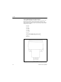
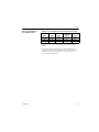
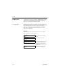
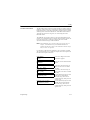
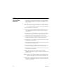
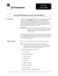
Appendix A contains a Table of Relative Thermal Conductivity of
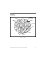
Common Gases. Figure 1-1 on the next page shows several of these
values graphically. In order to measure 0 to 25% H2 in N2, the
reference gas would be air (2-port version, sealed reference gas), and,
for calibration, the zero gas would be 100% N2 (i.e., 0 % H2) and the
span gas 25% H2 (balance N2). In order to measure 90-100% H2 in
N2, the reference gas would be 100% H2 (4-port version, flowing
reference gas), the zero gas would be 90% H2 (balance N2), and the
span gas 100% H2 (the same as the reference gas).
The TMO2-TC has a polarity adjustment switch which permits the
measurement of gases (such as CO2) with relative thermal
conductivity less than the background gas.
Features and Capabilities
1-3
11/1/95
Theory of Operation
(cont.)
Air/N2
SO2 CO2
CH4
Ne
He
H2
C4-C6
Figure 1-1: Relative Thermal Conductivity of Several Common Gases
1-4
Features and Capabilities
May 2003
System Description
The basic TMO2D-TC measurement system consists of a TMO2-TC
Transmitter mounted in a sample system and connected to a TMO2DTC Display. The sample system is mandatory, and can be provided by
GE Panametrics or constructed according to our recommendations.
The TMO2D-TC is supplied with a standard 10 ft. (3 m), 3-wire cable
for connecting the transmitter to the display module. Lengths up to
2,800 ft. (850 m) are optionally available.
TMO2-TC Transmitter
The TMO2-TC Transmitter is self-contained, consisting of the
thermal conductivity sensor and associated electronics. It requires 24
VDC power (1 amp maximum at power-up), which it receives from
the TMO2D-TC Display. It provides a 4-20 mA output signal to the
display module proportional to the thermal conductivity of the sample
gas and to the concentration of one of the gases in the binary mixture.
The TMO2-TC is designed to be installed in a sample system as close
as possible to the process sample point. Thus, it is available in two
environmental packages — weatherproof (NEMA-4X; IP65) and
explosion-proof (Class I, Groups C,D, Div. 1; Cenelec EEx d II C T6)
with the addition of flame arrestors to the sample/reference gas inlet
and outlet.
Each environmental package is available in a standard 2-port (sealed
reference gas) version, or optional 4-port (flowing reference gas)
version.
Features and Capabilities
1-5
11/1/95
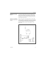
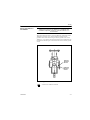
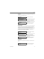
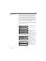
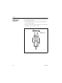
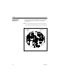
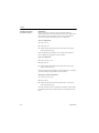
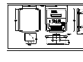
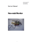
2-Port (Sealed Reference Gas) Version
This standard configuration (see Figure 1-2 below) is used for zerobased ranges with air or nitrogen at atmospheric pressure as the
balance or background gas. It utilizes air with desiccant in a factorysealed chamber as the reference gas. The following standard ranges
and gases are provided:
0 to 1%
0 to 2%
0 to 5%
0 to 10%
0 to 25%
0 to 50%
0 to 100%
H2 in N2
CO2 in N2 (minimum range 0 to 5% CO2)|
CO2 in Air (minimum range 0 to 5% CO2)
He in N2
He in Air
Figure 1-2: 2-Port (Sealed Reference Gas) TMO2-TC
1-6
Features and Capabilities
11/1/95
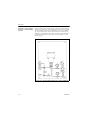
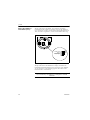
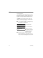
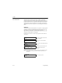
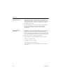
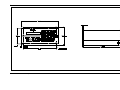
4-Port (Flowing Reference Gas) Version
This optional configuration (see Figure 1-3 on the following page) is
used for zero-suppressed ranges and some other special applications.
Typically, a flowing reference gas of 100% H2 or CO2 is used. The
following standard ranges and gases are provided:
90 to 100%
80 to 100%
H2 in N2
CO2 in N2/Air
He in N2/Air
Note: For factory calibration pricing on the standard ranges and
gases, or for pricing on other zero-suppressed ranges and
gases, please consult the factory.
The TMO2-TC is supplied with a standard measurement cell
operating temperature of 55 oC. An optional 70 oC cell operating
temperature is available.
Note: The 70 oC operating temperature should be selected only for
high temperature applications, since it will result in reduced
sensitivity.
Features and Capabilities
1-7
11/1/95
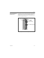
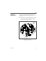
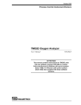
4-Port (Flowing Reference Gas) Version (cont.)
Top View
Bottom View
Figure 1-3: 4-Port (Flowing Reference Gas) TMO2-TC
1-8
Features and Capabilities
May 2003
Sample System
A sample system is mandatory for use with the TMO2-TC. The
design of the sample system will depend on the conditions of the
sample gas and the requirements of the application. In general, a
sample system must deliver a clean, representative sample to the
TMO2-TC at a temperature, pressure, and flow rate that are within
acceptable limits. Standard TMO2-TC sample conditions are as
follows:
•
Less than 50 oC (122 oF) temperature (for 55 oC cell operating
temperature)
•
Atmospheric pressure
•
0.5 SCFH (250 cc/min) flow rate
GE Panametrics offers sample systems for a wide variety of
applications. Three standard sample systems for the TMO2-TC are
shown in Chapter 2, Installation. For assistance in designing your
own sample system, please consult the factory.
TMO2D-TC Display
The TMO2D-TC Display receives a 4-20 mA signal from the TMO2TC Transmitter proportional to the concentration of one of the gases
in the binary mixture (the sample gas). It then displays the
concentration (and other information) on a 2-line x 24 character,
backlit LCD.
It requires 100/120/220/240 VAC power (35 watts max.), and
provides 24 VDC power to the TMO2-TC Transmitter. The standard
TMO2D-TC provides a 0/4-20 mA analog output; an RS232C digital
output; and dual Form C, SPDT relays for process monitoring and
control. Dual isolated 0/4-20 mA outputs and a second pair of relays
for Auto Cal are available as options.
The TMO2D-TC can be located adjacent to the TMO2-TC
Transmitter or as far as 2,800 ft. (850 m) away. It is provided in
bench, rack, panel, weatherproof (NEMA 4X; IP65), or explosionproof mounting configurations. The standard TMO2D-TC is suitable
for use in general purpose areas. A package suitable for use in Class I,
Div. 2 hazardous areas is available as an option. This package
includes hermetically-sealed alarm relays.
Extra Cable (optional)
GE Panametrics provides a 10 ft. (3 m) length of 3-wire, color-coded
cable with each TMO2D-TC to connect the transmitter to the display
module. The same cable is available in lengths up to 2,800 ft (850 m).
If you are using your own cable, refer to Chapter 2, Table 2-2, Cable
Requirements, for recommendations.
Features and Capabilities
1-9
11/1/95
Typical Applications
The TMO2D-TC can be used in a wide variety of industrial
applications where it is necessary to measure the concentration of one
component of a binary gas mixture. It can also be used in pseudobinary gas mixtures where the ratio of concentrations of the
background gas components remains constant, and in gaseous
mixtures where the thermal conductivity of the gas of interest is
significantly different from that of the background gas. Some typical
industries and applications include:
•
Metals Industry —
H2 in heat treat furnace atmospheres
•
Electric Power Industry —
H2 in generator cooling systems
•
Gas Production Industry —
Purity monitoring of argon, hydrogen, nitrogen, helium
•
Chemical Industry —
H2 in ammonia synthesis gas
H2 in methanol synthesis gas
H2 in chlorine plants
•
Food Industry —
CO2 in fermentation processes
Ethylene Oxide (ETO) sterilization
•
Steel Industry —
H2 in blast furnace top gas
•
Petroleum Industry —
H2 in hydrocarbon streams
Two very common applications are as follows:
1. H2 in N2 in heat treat furnace atmospheres - Zero-based 0-25%
H2, 2-Port (sealed reference gas, air)
2. H2 purity in H2 electricity generator cooling - Zero-suppressed,
80-100% H2, 4-Port (flowing reference gas, 100% H2)
For more details on these applications, refer to Appendix B,
Applications. For details on applications not shown in Appendix B, or
if you wish to discuss your own application, please consult the
factory.
1-10
Features and Capabilities
Chapter 2
Installation
Overview . . . . . . . . . . . . . . . . . . . . . . . . . . . . . . . . . . . . . . . . . . . . . .2-1
Introduction . . . . . . . . . . . . . . . . . . . . . . . . . . . . . . . . . . . . . . . . . . .2-2
Mounting the TMO2-TC Transmitter . . . . . . . . . . . . . . . . . . . . . . . .2-2
Mounting the Sample System . . . . . . . . . . . . . . . . . . . . . . . . . . . . .2-3
Mounting the TMO2D-TC Display . . . . . . . . . . . . . . . . . . . . . . . . . .2-6
Wiring the TMO2-TC Transmitter . . . . . . . . . . . . . . . . . . . . . . . . . .2-7
Wiring the TMO2D-TC Display . . . . . . . . . . . . . . . . . . . . . . . . . . . 2-12
May 2003
Overview
This chapter will describe how to mount and wire the TMO2-TC
Transmitter and its sample system, and the TMO2D-TC Display. You
will find the following topics discussed:
•
Introduction — A brief discussion of installation steps.
•
Mounting the TMO2-TC Transmitter — How to mount the
transmitter in a sample system.
•
Mounting the Sample System — Mounting and plumbing a GE
Panametrics sample system. Includes drawings of basic 2-Port and
4-Port sample systems, and an automatic 2-Port sample system.
•
Mounting the TMO2D-TC Display — How to mount the different
TMO2D-TC packaging configurations.
•
Wiring the TMO2-TC Transmitter — How to connect the
transmitter to the display module.
•
Wiring the TMO2D-TC Display — Connecting 100/120/220/240
VAC power, 0/4-20 mA output and alarm relay wiring to the
TMO2D-TC.
!WARNING!
TO ENSURE THE SAFE OPERATION OF THE
TMO2D-TC, YOU MUST INSTALL AND OPERATE IT
AS DESCRIBED IN THIS MANUAL. IN ADDITION, BE
SURE TO FOLLOW ALL APPLICABLE SAFETY
CODES AND REGULATIONS FOR INSTALLING
ELECTRICAL EQUIPMENT IN YOUR AREA.
PROCEDURES SHOULD BE PERFORMED BY
TRAINED SERVICE PERSONNEL.
!ATTENTION EUROPEAN CUSTOMERS!
IN ORDER TO MEET CE MARK REQUIREMENTS,
YOU MUST INSTALL CABLES AS DESCRIBED IN
APPENDIX H.
Note: Different versions of the TMO2D-TC display have different
PC boards. In Appendix C refer to the appropriate drawings,
as follows:
• Serial numbers 101 through 749, schematic 700-997 and
PCB assembly drawing 703-997.
• Serial numbers 750 or greater, schematics 700-1226 and
PCB assembly drawing 703-1226.
Installation
2-1
May 2003
Introduction
Installation of the TMO2D-TC analyzer typically consists of five
steps:
1. Mounting the TMO2-TC Transmitter in a sample system. (If you
purchased your sample system from GE Panametrics, this step has
already been done for you.)
2. Mounting, plumbing (and possibly wiring) the sample system.
3. Mounting the TMO2D-TC Display.
4. Making wiring connections between the transmitter and the
display module.
5. Making wiring connections to the TMO2D-TC Display for power,
outputs, and alarms.
Mounting the TMO2-TC
Transmitter
This section applies only if you are mounting the TMO2-TC
Transmitter to a sample system that has not been supplied by GE
Panametrics.
Your sample system should deliver a clean, representative sample to
the TMO2-TC at the proper temperature, pressure and flow rate. This
usually means a clean, dry sample (free of solid and liquid
particulates) at atmospheric pressure; a temperature no greater than
50 oC (122 oF); and a flow rate of approximately 0.5 SCFH (250 cc/
min). Factory calibration of the sensor is at atmospheric pressure and
0.5 SCFH - higher or lower operating pressures may necessitate fieldcalibration adjustment.
A simple sample system for a 2-Port TMO2-TC might have an inlet
and/or outlet flow regulating needle valve; a flow meter; and a
pressure gauge, in addition to the TMO2-TC Transmitter.
The TMO2-TC Transmitter should be mounted in the sample system
so that it is upright and level to within +/- 15o. Also, provide at least
9" of clearance above the top cover of the transmitter to allow access
to the transmitter printed circuit board (PCB) for calibration and
maintenance. For a 2-Port TMO2-TC, connect the sample system
Sample Inlet and Sample Outlet portions to the appropriate TMO2TC port (see Drawing 712-225 in Appendix C for port location). For a
4-Port system, also connect the Reference Inlet and Reference Outlet
portions to the appropriate TMO2-TC port (see Drawing 712-226 in
Appendix C for port location).
!WARNING!
FOR EXPLOSION-PROOF UNITS, BE SURE TO
CONFORM TO ALL SAFETY AND ELECTRICAL
CODE REQUIREMENTS.
2-2
Installation
May 2003
Mounting the Sample
System
You can order a complete sample system, which includes the TMO2TC Transmitter and all necessary components and sample tubing
mounted on a metal panel, from GE Panametrics. Several standard
sample systems are available; and custom-designed sample systems
can be built to your exact specifications. Following are descriptions
of three standard sample systems:
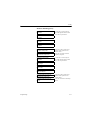
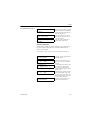
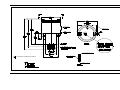
Manual, 2-Port (Sealed
Reference Gas) Sample
System
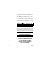
Figure 2-1 below shows a basic sample system for a 2-Port (sealed
reference gas) TMO2-TC. This sample system consists of inlet needle
valves for sample, zero, and span gases; a ball valve; a 2-port TMO2TC; a pressure gauge; and a flow meter. All components are mounted
on a painted steel plate. Other components could be added for
filtration (filter/coalescer), pressure control (regulator), or flow
control (pump).
Figure 2-1: Basic Sample System for a 2-Port TMO2-TC
Installation
2-3
May 2003
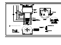
Manual, 4-Port (Flowing
Reference Gas) Sample
System
Figure 2-2 below shows a basic sample system for a 4-Port (flowing
reference gas) TMO2-TC. This sample system consists of inlet needle
valves for sample, reference, and calibration gases; a 4-port TMO2TC; two pressure gauges; and two flow meters. All components are
mounted on a painted steel plate. Other components could be added
for filtration (filter/coalescer), pressure control (regulator), or flow
control (pump).
Figure 2-2: Basic Sample System for a 4-Port TMO2-TC
2-4
Installation
11/1/95
Automatic, 2-Port
(Sealed Reference Gas)
Sample System
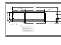
Figure 2-3 below shows an automatic sample system for a 2-Port
(sealed reference gas) TMO2-TC. This sample system requires the
Auto Cal option on the TMO2D-TC Display. It consists of inlet
needle valves for sample, zero, span, and optional calibration gases;
two electrically-actuated solenoid valves for gas selection; a 2-Port
TMO2-TC; a pressure gauge; a flowmeter; a regulating needle valve;
and a sample pump. All components are mounted on a painted steel
plate. Other components could be added for filtration (filter/
coalescer), or pressure control (regulator).
Figure 2-3: Automatic Sample System
for a 2-Port TMO2-TC
Installation
2-5
May 2003
Automatic, 2-Port
(Sealed Reference Gas)
Sample System (cont.)
When used in conjunction with the TMO2D-TC Display with the
Auto Cal option, the above sample system allows automatic
switching of sample, zero, and span gases during calibration. Refer to
Appendix B, Applications, for details on sample systems designed by
GE Panametrics for specific applications.
Mount the sample system as close as possible to the process sample
point. Once the sample system is mounted, connect all inlet and outlet
lines via the fittings on the sample system (1/4" compression). The
sample line leading from the process to the sample system should be
of 1/4" stainless steel tubing, and as short as possible in order to
insure a representative sample.
Mounting the TMO2DTC Display
The TMO2D-TC Display is available in five mounting
configurations: bench, rack, panel, weatherproof, and explosionproof. See Appendix C, Outline and Installation Drawings, for
dimensional drawings for each configuration, as well as rack/panel
cutout dimensions.
No special mounting requirements are needed for the TMO2D-TC
Display.
!WARNING!
FOR EXPLOSION-PROOF AND CLASS I, DIV. 2
UNITS, BE SURE TO CONFORM TO ALL SAFETY
AND ELECTRICAL CODE REQUIREMENTS.
!WARNING!
TO ENSURE THE SAFE OPERATION OF THE
TMO2D-TC, YOU MUST INSTALL AND OPERATE IT
AS DESCRIBED IN THIS MANUAL. IN ADDITION, BE
SURE TO FOLLOW ALL APPLICABLE SAFETY
CODES AND REGULATIONS FOR INSTALLING
ELECTRICAL EQUIPMENT IN YOUR AREA.
PROCEDURES SHOULD BE PERFORMED BY
TRAINED SERVICE PERSONNEL.
2-6
Installation
1/20/97
Wiring the TMO2-TC
Transmitter
Caution!
Always bring power to the TMO2-TC immediately after
installation, especially when it is mounted outdoors or in
a humid area.
This section describes how to wire the TMO2-TC Transmitter to the
TMO2D-TC Display. First, the transmitter enclosure must be
grounded. This can be done using an external ground screw on the
TMO2-TC, or, if required, an internal ground screw located below the
transmitter PCB. See Figure 2-4 below for the location of both ground
screws.
Internal
Ground
Screw
External
Ground
Screw
Figure 2-4: Location of Ground Screws
= Protective Conductor Terminal
Installation
2-7
11/1/95
Wiring the TMO2-TC
Transmitter (cont.)
Wiring connections to the TMO2-TC Transmitter are made to
terminal block TB1, which is accessed by removing the TMO2-TC
cover. See Figure 2-5 below for the location and pin designations for
TB1. Also refer to Appendix C, Outline and Installation Drawings.
1
2
3
4
Red
Blk
Wht
+24 VDC/1Amp 1
Return 2
Output Signal 3
No Connection 4
Figure 2-5: TMO2-TC Wiring Connections
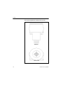
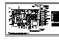
Wiring connections to the TMO2D-TC Display are made to the
terminal block labeled OXYGEN CELL at the rear of the TMO2DTC. See Figure 2-6 on the following page for the location of the
OXYGEN CELL terminal block.
Caution!
Do not make any connections to unassigned or unused
terminals.
2-8
Installation
11/1/95
Wiring the TMO2-TC
Transmitter (cont.)
High
Alarm
TMO2D-TC
SPARE
INPUTS
RECORDERS
0/4-20 mA
IN2
IN1
RTN
+24V
COMP
OX
RTN
+24V
OXYGEN
Cell
AUTOCAL
REC A REC B PROCESS
+
-+ -
CAL
Low
Alarm
ALARMS
LOW
HIGH
C NC NO C NC NOC NC NOC NC NO
Alarm
Power
1 2 3 4
TMO2-TC
Outlet
REC
A
REC
B
+
_
Solonoid Valve
Power
+
_
Zero
Span
Gas
Gas
Process Gas Inlet
Auto-Calibration System
Figure 2-6: TMO2D-TC Wiring Connections
Installation
2-9
May 2003
Wiring the TMO2-TC
Transmitter (cont.)
Table 2-2 below shows the transmitter to display module wiring
connections using the standard GE Panametrics TMO2D-TC cable.
This cable can be used for distances up to 2,800 ft (850 m). If you are
using your own cable, refer to Table 2-2 for cable requirements.
Table 2-1: Cable Requirements
Max Cable Length
Cable Size
Feet
Meters
AWG
Sq.
Millimeters
450
130
22
0.35
700
200
20
0.6
1,050
320
18
1.0
1,700
500
16
1.2
2,800
850
14
2.0
4,000
1,200
12
3.0
Use the following steps to make the proper connections:
1. Route the cable into the transmitter through one of the 3/4"
conduit holes.
!WARNING!
BE SURE TO PLUG UP THE UNUSED CONDUIT
HOLE ON THE SIDE OF THE TRANSMITTER IN
ORDER TO MAINTAIN THE APPROPRIATE
WEATHERPROOF OR EXPLOSION-PROOF
RATING.
2. Unplug TB1 by carefully pulling it directly up without bending the
pins attached to the PCB.
3. Loosen the TB1 side screws and insert the colored wires into the
corresponding openings on top of TB1. See Table 2-1 above for
color-coded pin designations.
!WARNING!
BE SURE THAT +24 VDC (RED WIRE) IS
CONNECTED TO TERMINAL TB1-1. CONNECTING
+24 VDC POWER TO ANY OTHER TERMINAL WILL
DAMAGE THE TMO2-TC PCB, REQUIRING
FACTORY REPAIR.
2-10
Installation
11/1/95
Wiring the TMO2-TC
Transmitter (cont.)
Table 2-2: Transmitter Power and Output Connections
Wire
Color
Gage
Transmitter
TB1
Display
+24 VDC
Red
14 AWG
Pin 1
+24V
Return
Black
14 AWG
Pin 2
RTN
Signal
White
22 AWG
Pin 3
OX
4. Tighten the side screws, and carefully plug TB1 back onto the
PCB.
5. Connect the other end of the cable in a similar manner to the
OXYGEN CELL terminal block located on the rear panel of the
TMO2D-TC Display. See Table 2-1 on the previous page for
color-coded pin designations.
Installation
2-11
1/20/97
Wiring the TMO2D-TC
Display
Figure 2-6 on page 2-9 shows possible output wiring connections
between the TMO2D-TC Display and recorders, alarms, and
automatic sample systems. Note that the standard TMO2D-TC has a
single, non-isolated 0/4-20 mA output (RCDR A) and dual Form C
SPDT alarm relays (ALARMS). Dual isolated 0/4-20 mA outputs
(RCDR A/RCDR B) and dual auto calibration (Auto Cal) relays are
optional.
The alarm relays can be wired in a “fail-safe” configuration that will
allow a contact closure when the H2 level falls below a certain point
or rises above a certain point, or when a power failure occurs. For
example, to have a contact closure when the H2 level falls below 1%
or rises above 5%, or in the event of a power failure, do the following:
TMO2D-TC Alarm
Wire
Program
For Use As
LOW
COM/NC
5% H2
HIGH
HIGH
COM/NC
1% H2
LOW
Note: See Chapter 4, Programming the TMO2D-TC, The Alarms
Menu, for information on programming the alarm set points.
When the LOW alarm is wired and programmed as above, a loss of
power or an H2 reading greater than 5% causes a contact closure that
can be used as a HIGH or “fail-safe” alarm.
When the HIGH alarm is wired and programmed as above, a loss of
power or an H2 reading less than 1% causes a contact closure that can
be used as a LOW or “fail-safe” alarm.
!ATTENTION EUROPEAN CUSTOMERS!
IN ORDER TO MEET CE MARK REQUIREMENTS,
YOU MUST SHIELD AND GROUND ELECTRICAL
CABLES AS DESCRIBED IN APPENDIX H.
!WARNING!
TO ENSURE THE SAFE OPERATION OF THE
TMO2D-TC, YOU MUST INSTALL AND OPERATE IT
AS DESCRIBED IN THIS MANUAL. IN ADDITION, BE
SURE TO FOLLOW ALL APPLICABLE SAFETY
CODES AND REGULATIONS FOR INSTALLING
ELECTRICAL EQUIPMENT IN YOUR AREA.
PROCEDURES SHOULD BE PERFORMED BY
TRAINED SERVICE PERSONNEL.
2-12
Installation
1/20/97
Wiring the TMO2D-TC
Display (cont.)
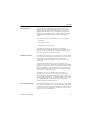
The TMO2D-TC also has a bi-directional, industry standard RS232C
serial port, which can be connected to a terminal or PC that supports
the RS232C protocol. Figure 2-7 below shows the wiring pin
designations. The 25-pin, male D connector is located at the right on
the rear of the TMO2D-TC Display.
J8
Pin 14
Pin 1
Pin 2 = Transmit
(from)
Pin 3 = Receive (to)
Pin 7 = Return (ground)
Figure 2-7: RS232C Wiring Connections
Installation
2-13
1/20/97
Wiring the TMO2D-TC
Display (cont.)
The TMO2D-TC Display is connected to 100/120/220/240 VAC
power using the supplied power cord.
Caution!
The interconnecting wiring between the TMO2-TC
Transmitter and TMO2D-TC Display must be completed
before powering up.
Note: The power cord is the main disconnect device.
Note:
= Protective Conductor Terminal
IMPORTANT: To comply with the European Low Voltage Directive,
you must install a switch or circuit breaker on the
input power line. For greatest safety, locate the
circuit breaker or switch near the unit that the line
serves.
2-14
Installation
Chapter 3
Operation
Overview . . . . . . . . . . . . . . . . . . . . . . . . . . . . . . . . . . . . . . . . . . . . . .3-1
Introduction . . . . . . . . . . . . . . . . . . . . . . . . . . . . . . . . . . . . . . . . . . .3-1
Powering Up the TMO2D-TC Analyzer . . . . . . . . . . . . . . . . . . . . . .3-1
Establishing a Flow of Sample Gas . . . . . . . . . . . . . . . . . . . . . . . .3-2
Operating the TMO2D-TC Display. . . . . . . . . . . . . . . . . . . . . . . . . .3-3
1/20/97
Overview
Introduction
This chapter provides information on operating the TMO2D-TC
analyzer. You will find the following topics discussed:
•
Introduction — A brief discussion of operational considerations.
•
Powering Up the TMO2D-TC Analyzer — How to start the
TMO2D-TC.
•
Establishing a Flow of Sample Gas — Basic sample gas
considerations.
•
Operating the TMO2D-TC Display — A description of the
TMO2D-TC LCD display and keypad.
The TMO2D-TC operation consists of only three steps:
1. Supplying power to the analyzer and turning it on.
2. Establishing a flow of sample gas through the system.
3. Operating the display module.
If you have not already done so, please read Chapter 2, Installation,
for details on mounting and wiring the TMO2-TC Transmitter, the
sample system, and the TMO2D-TC Display.
Powering Up the
TMO2D-TC Analyzer
The TMO2D-TC Display has a power switch located at the top right
of the front panel. It will begin operation as soon as it is turned to the
ON position.
Note: The power cord is the main disconnect device.
Note: If your TMO2D-TC was supplied in a weatherproof enclosure
or was modified for use in Class I, Div. 2 hazardous areas, the
power switch will be inoperative. The TMO2D-TC will begin
operating as soon as it is connected to a 100/120/220/240
VAC power source.
The TMO2D-TC Display will provide 24 VDC power to the TMO2TC Transmitter. Because the transmitter is controlled at a constant
55oC (131oF) operating temperature, allow 30 minutes for the unit to
warm up and reach temperature stability. During this time, you can
establish a sample gas flow through the sample system.
IMPORTANT: To comply with the European Low Voltage Directive,
you must install a switch or circuit breaker on the
input power line. For greatest safety, locate the
circuit breaker or switch near the unit that the line
serves.
Operation
3-1
May 2003
Powering Up the
TMO2D-TC Analyzer
(cont.)
When the display module is first turned on, it will show the firmware
version installed. For example:
GE Panametrics
TMO2D STD.00X.X
Next it will do some internal testing:
GE Panametrics
Testing RAM ... Passed.
The above sequence should take about 10 seconds. The display
module then begins taking measurements from the transmitter, and
the LCD displays the gas concentration, the time, and the Alarm
status. Allow the transmitter 30 minutes to warm up before accepting
data from the TMO2D-TC.
Establishing a Flow of
Sample Gas
Open the necessary valves to establish a sample gas flow of 0.5 SCFH
(250 cc/min) at atmospheric pressure. Make sure that nothing
obstructs the flow of sample gas, thereby causing a pressure build-up
in the sensing chamber. For proper operation, the TMO2-TC
Transmitter should be vented to atmosphere.
Note: Unless otherwise specified, the TMO2-TC is factory
calibrated at atmospheric pressure and 0.5 SCFH (250 cc/
min) and should therefore be operated at atmospheric
pressure. Operating the TMO2-TC at any other pressure will
necessitate a field calibration at that pressure in order to
maintain accuracy. See Chapter 5, Calibration.
If you are using the 4-Port (flowing reference gas) configuration,
open the necessary valves to establish a reference gas flow of 0.5
SCFH (250 cc/min) at atmospheric pressure. Note that you can use a
reference gas flow as low as 5 cc/min in order to conserve gas.
3-2
Operation
May 2003
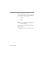
Operating the TMO2DTC Display
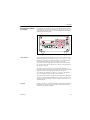
The TMO2D-TC Display has a 2-line x 24 character backlit Liquid
Crystal Display (LCD) screen, and a 16-key keypad (see Figure 3-1).
After displaying the firmware version and testing RAM, the display
module enters Operate Mode.
Figure 3-1: TMO2D-TC Display and Keypad
LCD Display
In Operate Mode, the left side of the top line of the LCD shows the
name of the gas being measured (e.g., H2, N2, SO2, CO2). It was set at
the factory according to initial specifications. If you should need to
change the name of the gas, refer to Appendix E, Special
Programming. This manual will refer to the gas being measured as
H2. The left side of the bottom line shows the gas concentration in %
(see Figure 3-1 above).
The right side of the top line is a clock. When the TMO2D-TC is
powered up, this clock will start from 00:00:00. The current time (and
date) can be entered in Programming Mode (see Chapter 4,
Programming the TMO2D-TC). However, if power to the TMO2DTC is interrupted, the clock will be reset to 00:00:00.
The right side of the bottom line displays the alarm status. The word
“Alarm:” is displayed. If the HIGH alarm is activated, an “H” will be
displayed in reverse lettering. If the LOW alarm is activated, an “L”
will be displayed.
Keypad
Operation
Except for the No key, which is used to enter Programming Mode, the
keypad does not function in Operate Mode. Pressing any other key
will activate the display backlight.
3-3
Chapter 4
Programming
Overview . . . . . . . . . . . . . . . . . . . . . . . . . . . . . . . . . . . . . . . . . . . . . .4-1
Introduction . . . . . . . . . . . . . . . . . . . . . . . . . . . . . . . . . . . . . . . . . . .4-2
Key Functions. . . . . . . . . . . . . . . . . . . . . . . . . . . . . . . . . . . . . . . . . .4-3
Entering Programming Mode . . . . . . . . . . . . . . . . . . . . . . . . . . . . .4-5
Menu Navigation. . . . . . . . . . . . . . . . . . . . . . . . . . . . . . . . . . . . . . . .4-5
The Main Menu . . . . . . . . . . . . . . . . . . . . . . . . . . . . . . . . . . . . . . . . .4-6
11/1/95
Overview
Programming
This chapter provides information on programming the TMO2D-TC
Display using either the 16-key keypad or the RS232C serial port.
You will find the following topics discussed:
•
Introduction — A brief overview of the TMO2D-TC user program.
•
Key Functions — Keypad key functions and their RS232C
equivalents when in Programming Mode.
•
Entering Programming Mode — How to enter Programming Mode
from Operate Mode in order to access the user program.
•
Menu Navigation — How to navigate the TMO2D-TC menu
structure.
•
The Main Menu — A description of the Main menu functions.
•
The Setup Menu — A description of the Setup menu functions.
•
The Recorders Menu — A description of the Recorders menu
functions.
•
The Alarms Menu — A description of the Alarms menu functions.
•
The Tests Menu — A description of the Tests menu functions.
•
The Calibration Menu — A description of the Calibration menu
functions.
4-1
11/1/95
Introduction
The TMO2D-TC Display contains an interactive, user-friendly
program that allows the user to customize the TMO2D-TC to their
application and change operating parameters as desired. The program
is accessed through the TMO2D-TC keypad and LCD display, or the
RS232C serial port using an ASCII terminal or PC.
Data entered into the TMO2D-TC by the user overrides any
previously entered data, and is retained in memory for several years,
even if power to the TMO2D-TC is interrupted.
Note: The time in the TMO2D-TC is reset to 00:00:00 if power is
interrupted. The date information is retained if power is
interrupted, but may be incorrect if power is not restored
immediately. Both date and time should be re-entered in the
event of power interruption.
!WARNING!
IF THE CABLE CONNECTING THE TMO2D-TC
DISPLAY TO THE TMO2-TC TRANSMITTER IS
DISCONNECTED WHILE THE TMO2D-TC IS
POWERED UP, DATA MAY BE LOST. ALWAYS
REMOVE POWER FROM THE DISPLAY MODULE
BEFORE DISCONNECTING THE TMO2D-TC TO
TMO2-TC CABLE.
4-2
Programming
11/1/95
Key Functions
When the TMO2D-TC is in Operate Mode, it will ignore all keys
except the No key. On receipt of a No, the LCD will display Enter
Code:, and await the user program entry code, 1 2 3. During code
entry, the TMO2D-TC continues to update the data display, alarm
status, and recorder output.
If the correct code is entered, the TMO2D-TC switches to
Programming Mode. While it is in Programming Mode, data
collection is suspended, and alarm status and recorder outputs are
held at their current values.
In Programming Mode, the keypad keys are divided into three
groups: Yes/No, Selector, and Data Entry:
Yes/No:
The Yes key is used to select a displayed menu option
or to confirm a numeric entry. The No key is used to
scroll forward to the next menu option or to clear a
numeric entry.
Selector:
The Left and Right Arrow keys are used as selector
keys. The Left Arrow key is used to step backward
through a displayed list of menu options, or as a backspace (erase) key during numeric entry. The Right
Arrow key is used to step forward through a displayed
list of menu options. It is equivalent to the No key.
Data
Entry:
The 0-9, -, and . keys are used to enter numeric values.
All keypad and most display operations can be performed remotely
on the RS232C serial port using a terminal or PC that supports the
RS232C protocol. Table 4-1 on the next page provides a list of
keypad keys (left column) and their ASCII (center column) and
terminal/PC (right column) equivalents.
Programming
4-3
11/1/95
Key Functions (cont.)
4-4
Table 4-1: TMO2D-TC RS232C Serial Port
Corresponding Keys
TMO2D-TC
Keypad
ASCII
Terminal/PC Keys
0
030
0
1
031
1
2
032
2
3
033
3
4
034
4
5
035
5
6
036
6
7
037
7
8
038
8
9
039
9
-
02D
-
.
02E
.
Y
00D
ENTER_
N
01B
ESCAPE
←
→
008
BACKSPACE
020
SPACE BAR
Programming
11/1/95
Entering Programming
Mode
When the TMO2D-TC is turned on, it enters Operate Mode (after
approx. 10 seconds). In order to enter data into the user program or to
check previously entered values, the TMO2D-TC must be switched to
Programming Mode. To enter Programming Mode:
1. Press the No key.
2. The top line of the display will show Enter Code:
3. Key in the code 1 2 3, pressing each key slowly and firmly. The
display will show an * after each digit is entered.
Note: If an incorrect code is entered, or a non-numeric (Yes/No or
Arrow) key is pressed, or the keys are pressed too quickly, the
TMO2D-TC will return to Operate Mode, and the user must
press No again to re-enter the code.
4. The display will now show:
MAIN MENU
Setup?
5. The TMO2D-TC is now in Programming Mode, ready for user
input.
Menu Navigation
When a menu item is being displayed, the first line of the LCD shows
the title of the current menu in capital letters. The second line shows
the current menu option followed by a question mark. Press Yes to
select a displayed option, No or Right Arrow to move on to the next
option, or Left Arrow to move back to the previous option.
Note: The menu options are circular — skipping over the last option
in the list returns to the first option.
Programming
4-5
11/1/95
The Main Menu
The Main menu consists of six submenus: Setup, Recorders, Alarms,
Tests, Calibration, and Resume. Selecting Resume returns the
TMO2D-TC to Operate Mode. Refer to Appendix D, Menu Flow
Diagrams, for a flow diagram of the Main menu.
The Setup Menu
The Setup menu consists of seven options: Set Time, Set Date, Set
Backlight, Set Display, Set Communications, Set Error Handling, and
Done. These options allow the user to change basic operating
parameters. Selecting Done returns the TMO2D-TC to the Main
menu. Refer to Appendix D, Menu Flow Diagrams, for a flow
diagram of the Setup menu.
Set Time
Set Time sets the current time in 24-hour format. For example, to
enter 1:15 PM (13.15 in 24-hour time):
MAIN MENU
Setup?
Press Yes to enter the Setup
menu.
SETUP MENU
Set Time?
Press Yes to set the time.
Enter 24 hour time:
Use the Data Entry keys to enter
13.15 (the X’s represent the
previous entry). Press Yes to
confirm the entry; then press Yes
again to exit.
Press No to move to the next
option on the Setup menu.
HH.MM [XX.XX]: 13.15
SETUP MENU
Set Time?
4-6
Programming
11/1/95
Set Date
Set Date sets the current date in USA (month, day, year) format. For
example, to enter August 12, 1994:
SETUP MENU
Set Date?
Press Yes to set the date.
Enter Date (MM.DD.YY):
Use the Data Entry keys to enter
08.12.94 (the X’s represent the
previous entry). Press Yes to
confirm the entry; then press Yes
again to exit.
Press No to move to the next
option on the Setup menu.
XX.XX.XX]: 08.12.94
SETUP MENU
Set Date?
Set Backlight
The LCD contains an electro-luminescent (EL) panel to enhance the
readability of the screen in dim light. EL panels have a finite life
span, dimming with use. To maintain the life of the EL backlight, the
TMO2D-TC will automatically turn the backlight off after a
predetermined time period. The backlight time-out period can be set
from 0 (never on) to 60 minutes. The default is 3 minutes. For
example, to enter a time-out of 10 minutes:
SETUP MENU
Set Backlight?
Press Yes to set the backlight
time-out period.
SETUP MENU
Use the Data Entry keys to enter
10 (the X’s represent the
previous entry). Press Yes to
confirm the entry; then press Yes
again to exit.
Press No to move to the next
option on the Setup menu.
Remain ON (min) [XX]: 10
SETUP MENU
Set Backlight?
Set Display
This option is not applicable to the TMO2D-TC and should not be
used.
SETUP MENU
Set Display?
Programming
Press No to move to the next
option on the Setup menu.
4-7
11/1/95
Set Communications
The Set Communications menu consists of three options: Set Baud
Rate, Set Update Rate, and Done. These options allow the user to
change RS232C communications parameters. Selecting Done returns
the TMO2D-TC to the Setup menu. Refer to Appendix D, Menu Flow
Diagrams, for a flow diagram of the Set Communications menu.
Set Baud Rate
The TMO2D-TC supports communications rates of 9600, 4800,
2400, 1200, and 300 baud. The default setting is 9600 baud, Word
size is fixed at 8 bits, 1 stop bit, NO parity.
Note: The use of 300 baud greatly limits the computation speed of
the TMO2D-TC, and is not recommended. It is provided solely
for compatibility with older equipment.
SETUP MENU
Set Communications?
Press Yes to enter the Set
Communications menu.
SET COMMUNICATIONS
Press Yes to set the baud rate.
Set Baud Rate?
SELECT BAUD RATE
9600 baud?
Use the No or Arrow keys to
scroll through the choices (9600,
4800, 2400, 1200, 300). Press
Yes to select the desired baud
rate and exit to the Set
Communications submenu.
Note: The baud rate can also be changed via a terminal/PC
connected to the RS232C port; however, this practice is not
recommended. Since the TMO2D-TC will immediately change
to the new baud rate, the display and keyboard operation will
not be correct until the baud rate of the terminal/PC is
changed to match the new baud rate set in the TMO2D-TC.
4-8
Programming
11/1/95
Set Update Rate
This option is used to change the interval at which data is sent to the
RS232C serial port. The data update rate can be set from 0 (no data
sent) to 300 seconds. The default rate is 1 second. For example, to set
an update rate of 180 seconds:
SETUP MENU
Set Update Rate?
Press Yes to set the update rate.
SET COMMUNICATIONS
Done?
Use the Data Entry keys to enter
180 (the X’s represent the
previous entry). Press Yes to
confirm the entry; then press Yes
again to exit.
Press No to move to the next
option on the SET
COMMUNICATIONS
submenu.
Press Yes to exit to the Setup
menu.
SETUP MENU
Set Communications?
Press No to move to the next
option on the Setup menu.
Data Interval [XXX]: 180
SET COMMUNICATIONS
Set Update Rate?
SET COMMUNICATIONS
Programming
4-9
11/1/95
Set Error Handling
The Set Error Handling option is used to program the LCD, output(s),
and alarms to respond to an invalid H2 measurement (under-range or
over-range) that occurs when the TMO2D-TC is in Operate mode. An
invalid measurement occurs if the H2 reading is 1 mA or less, or 24
mA or greater.
Note: Error handling for an invalid H2 measurement is independent
of error handling for Auto Cal (see “Auto Cal Parameters” in
the Calibration menu). If both error conditions occur
simultaneously, error handling for the invalid H2
measurement will take precedence.
Follow the steps below to enable Error Handling, set the LCD, and
select the output and alarm responses:
SETUP MENU
Set Error Handling?
Press Yes to select the Set Error
Handling option.
Enable Error Handling:
Press the No or the Arrow keys
to select YES. Press Yes to
confirm.
[YES]
no
Note: If you select NO and press Yes to confirm, you will be
immediately returned to the Setup menu.
SYSTEM ERROR EFFECTS
Set Display Response?
Press Yes to set the LCD
response.
Display System Error?
Press the No or the Arrow keys
to select your choice. Press Yes
to confirm.
Press No to move to the next
option on the System Error
Effects menu.
yes
[NO]
SYSTEM ERROR EFFECTS
Set Display Response?
SYSTEM ERROR EFFECTS
Set Alarm Response?
4-10
Press Yes to set the alarm
response.
Programming
11/1/95
Set Error Handling (cont.)
Select Alarm Effect?
No Effect?
Use the No or Arrow keys to
scroll through the choices and
press Yes at your choice.
Select Alarm Effect?
Trip High?
Select Alarm Effect?
Trip Low?
Select Alarm Effect?
Trip Both?
SYSTEM ERROR EFFECTS
Set Alarm Response?
SYSTEM ERROR EFFECTS
Set Recorder Response?
Select Recorder Effect?
No Effect?
Press No to move to the next
option on the System Error
Effects menu.
Press Yes to set the recorder
output(s) response.
Use the No or Arrow keys to
scroll through the choices and
press Yes at your choice.
Select Recorder Effect?
Force High?
Select Recorder Effect?
Force Low?
Select Recorder Effect?
Hold Last Value?
SYSTEM ERROR EFFECTS
Set Recorder Response?
SYSTEM ERROR EFFECTS
Done?
Programming
Press No to move to the next
option on the System Error
Effects menu.
Press Yes to return to the Setup
menu.
4-11
11/1/95
Set Error Handling (cont.)
4-12
SETUP MENU
Set Error Handling?
Press No to move to the next
option on the Setup menu.
SETUP MENU
Done?
Press Yes to return to the Main
menu.
MAIN MENU
Setup?
Press No to move to the next
option on the Main menu.
Programming
11/1/95
The Recorders Menu
The Recorders menu is used to scale the 0/4-20 mA analog output(s).
Selecting A allows the user to scale the first analog output. Selecting
B allows the user to scale the second analog output (if one is present).
Selecting Done returns the TMO2D-TC to the Main menu. Refer to
Appendix D, Menu Flow Diagrams, for a flow diagram of the
Recorders menu.
The TMO2D-TC provides a choice of one non-isolated 0/4-20 mA
output, or two isolated 0/4-20 mA outputs. Both recorder options can
be set for a 0-20 mA or 4-20 mA response, and can be scaled
anywhere within the range of the transmitter.
Note: The TMO2D-TC user program will accept settings for two
outputs, A and B. However, if the TMO2D-TC has been
purchased with only a single, non-isolated 0/4-20 mA output,
only recorder A is effective.
Use the steps in the following example to set up recorders A and B.
We will set recorder A for a 4-20 mA output, with 4 mA equal to 0%
H2 and 20 mA equal to 100% H2.
MAIN MENU
Setup?
Press No or Right Arrow until
Recorders? appears.
MAIN MENU
Press Yes to enter the Recorders
menu.
Recorders?
Select Recorder to set:
[A]
B
done
Press No or the Arrow keys to
select A. Press Yes to confirm
the entry.
Rcd A Output (mA):
Press No or the Arrow keys to
select 4-20. Press Yes to confirm
the entry.
Use the Data Entry keys to enter
0.00 (the X’s represent the
previous entry). Press Yes to
confirm the entry; then press Yes
again to exit.
Use the Data Entry keys to enter
100.00 (the X’s represent the
0-20
[4-20]
Recorder A 4 mA Value
%H2 [XX.XX]: 0.00
Recorder A 20 mA Value
%H2 [XXX.XX]: 100.00
previous entry). Press Yes to
confirm the entry; then press Yes
again to exit.
Programming
4-13
11/1/95
The Recorders Menu
(cont.)
Select Recorder to set:
[A]
B
done
MAIN MENU
Recorders?
4-14
Recorder B is scaled in the same
manner. After Recorder B is
scaled, use the No or Arrow keys
to select DONE. Press Yes to
return to the Main menu.
Press No to move to the next
option on the Main menu.
Programming
11/1/95
The Alarms Menu
The TMO2D-TC is provided with two single-pole double throw
(SPDT), Form C alarm relays for use in activating alarm devices. See
Chapter 6, Specifications, for details on relay specifications, and
Chapter 2, Installation, for wiring recommendations. Both relays
provide a normally-open (NO) and a normally-closed (NC) set of
contacts. The alarms are addressed as HIGH or LOW. The HIGH
alarm relay will change state when the current reading becomes
greater than or equal to the HIGH alarm set point. The LOW alarm
relay will change state when the current reading becomes less than or
equal to the LOW alarm set point. Refer to Appendix D, Menu Flow
Diagrams, for a flow diagram of the Alarms option.
Use the steps in the following example to set the HIGH and LOW
alarm relays. We will set the HIGH alarm relay to 75% H2, and the
LOW alarm relay to 25% H2.
MAIN MENU
Setup?
Press No or Right Arrow until
Alarms? appears.
MAIN MENU
Press Yes to enter the Alarms
menu.
Alarms?
Select Alarm to set:
[HIGH] low done
Press No or the Arrow keys to
select HIGH. Press Yes to
confirm the entry.
Enter Alarm Setpoint:
High %H2 [XX.XX]:
Use the Data Entry keys to enter
75.00 (the X’s represent
the previous entry). Press Yes to
confirm the entry; then press Yes
again to exit.
Press No or the Arrow keys to
select LOW. Press Yes to
confirm the entry.
Select Alarm to set:
[HIGH] low done
Enter Alarm Setpoint:
Low %H2 [XX.XX]:
Select Alarm to set:
high [LOW] done
MAIN MENU
Alarms?
Programming
Use the Data Entry keys to enter
25.00 (the X’s represent the
previous entry). Press Yes to
confirm the entry; then press Yes
again to exit.
Press No or the Arrow keys to
select DONE. Press Yes to return
to the Main menu.
Press No to move to the next
option on the Main menu.
4-15
11/1/95
The Tests Menu
The Tests menu consists of four options: DVM Test, Recorder
Calibrate, Alarms Test, and Done. These options allow the user to
perform operational tests on the analog outputs and alarm relays, and
to directly measure the raw signal from the TMO2-TC Transmitter.
Selecting Done returns the TMO2D-TC to the Main menu. Refer to
Appendix D, Menu Flow Diagrams, for a flow diagram of the Tests
menu.
DVM Test
The DVM test allows the TMO2D-TC to operate as a simple, digital
voltmeter to measure, in milliamps, the signal being received from
the TMO2-TC Transmitter. The TMO2D-TC is updated
approximately twenty times per second, facilitating connection and
calibration of the TMO2-TC Transmitter.
Follow the steps below to test the input signal from the TMO2-TC
Transmitter:
MAIN MENU
Setup?
Press No or Right Arrow until
Tests? appears.
MAIN MENU
Tests?
Press Yes to enter the Tests
menu.
TESTS
DVM Test?
Press Yes to enter the DVM test
option.
Select DVM Input:
Press No or the Arrow keys to
select GAS. Press Yes to
confirm.
[GAS]
comp
done
Note: The COMP option is not applicable to the TMO2D-TC, and
should not be used. If you select COMP by mistake, you
should see:
H2 DVM TEST
Press any key to exit.
0.00 mA
4-16
Programming
11/1/95
The Tests Menu (cont.)
The X’s represent the mA signal
from the TMO2-TC Transmitter,
H2 DVM TEST
XX.XX mA
Select DVM Input:
[GAS]
comp
done
TESTS
DVM Test?
which will update continuously.
Press any key to exit.
Press No or the Arrow keys to
select DONE. Press Yes to exit
to the Tests menu.
Press No to move to the next
option on the Tests menu.
Recorder Calibrate
The Recorder Calibrate test allows a selected % gas composition to
be output to the recording device to facilitate adjustment of the
device’s zero and span.
For example, to enter a %H2 of 36.39 to be output to recorder A:
TESTS
Recorder Calibrate?
Press Yes to enter the Recorder
Calibrate option.
Select Recorder to test:
Press No or the Arrow keys to
select A. Press Yes to confirm
the entry.
Use the Data Entry keys to enter
36.39 (the X’s represent the
previous entry). Press Yes to
confirm the entry; then press Yes
again to exit.
Recorder B (if present) is tested
in the same manner. After you
are done, press No or the Arrow
keys to select DONE. Press Yes
to exit to the Tests menu.
Press No to move to the next
option on the Tests menu.
[A]
B
done
Set Recorder A to:
%H2 [XX.XX]: 36.39
Select Recorder to test:
[A]
B
done
TESTS
Recorder Calibrate?
Programming
4-17
11/1/95
Alarms Test
The Alarms test enables you to trip and reset the alarm relays using
the keypad, in order to test the operation of external alarm devices
and circuits. For example, to test the HIGH alarm relay:
TESTS
Alarms Test?
Press Yes to enter the Alarms test
option.
Select Alarm to test:
Press No or the Arrow keys to
select HIGH. Press Yes to
confirm the entry.
Press No or the Arrow keys to
select ON. Press Yes to confirm.
[HIGH]
low
done
Turn High Alarm:
[ON] off done
Note: Upon selecting the ON option and pressing Yes, the HIGH
alarm relay will turn on, and the brackets will automatically
move to OFF.
Turn High Alarm:
on [OFF] done
Press Yes to turn the HIGH
alarm off.
Note: Upon selecting the OFF option and pressing Yes, the HIGH
alarm relay will turn off and the brackets will automatically
move to ON.
Turn High Alarm:
[ON] off done
Press No or the Arrow keys to
select DONE. Press Yes to exit.
Select Alarm to test:
The LOW alarm is tested in
the same manner. After you
are done, press No or the Arrow
keys to select DONE. Press Yes
to exit to the Tests menu.
Press No to move to the next
option on the Tests menu.
[HIGH]
low
TESTS
Alarms Test?
Done?
Press Yes to return to the Main
menu.
MAIN MENU
Tests?
Press No to move to the next
option on the Main menu.
TESTS
4-18
done
Programming
May 2003
The Calibration Menu
The Calibration menu consists of three options: Auto Cal Parameters,
Edit Calibration Data, and Done. These options allow the user to
perform automatic zero and span calibration of the TMO2D-TC, and
to enter measurement parameters and calibration data. Selecting Done
returns the TMO2D-TC to the Main menu. Refer to Appendix D,
Menu Flow Diagrams, for a flow diagram of the Calibration menu.
Auto Cal Parameters
The TMO2D-TC can be programmed to perform an automatic
calibration procedure (Auto Cal) at specified time intervals ranging
from minutes to months. By performing measurements on two
calibration gases (zero and span), the TMO2D-TC can automatically
correct for changes in the response of the TMO2-TC Transmitter
without operator intervention. Auto Cal does not physically
recalibrate the TMO2-TC Transmitter, but instead creates a drift
curve to the TMO2-TC calibration data that is stored in memory in
the TMO2D-TC Display. Refer to Chapter 5, Calibration, for details
on manually calibrating the TMO2-TC Transmitter.
Note: Auto Cal requires the CAL option to be ordered with the
TMO2D-TC. It also requires a sample system with
electrically-actuated solenoid valves, and zero and span gases
for use during Auto Cal. See Figure 2-3 for a description of a
suitable sample system. If you do not presently have the Auto
Cal option or the proper sample system, please consult GE
Panametrics for assistance.
!WARNING!
USING THE AUTO CAL PROCEDURE WITHOUT
THE OPTIONS DESCRIBED ABOVE WILL
PRODUCE AN ERRONEOUS CALIBRATION AND
PREVENT PROPER OPERATION
OF THE TMO2D-TC.
At a user-specified time interval, the TMO2D-TC activates a solenoid
valve on the sample system. This isolates the transmitter from the
process stream, and connects it instead to the span calibration gas.
After a programmable equilibration time, to allow the span gas to
completely replace the process gas, measurements are taken of the
span calibration gas. The TMO2D-TC then activates a second
solenoid valve to connect to the zero calibration gas. After
equilibration, measurements are taken of the zero calibration gas. The
TMO2D-TC then reconnects the transmitter to the process stream. A
final settling time takes place while the process gas completely
replaces the zero gas.
Programming
4-19
11/1/95
The Calibration Menu
(cont.)
Once settling has been completed, if no error has occurred, the
TMO2D-TC calculates the amount of drift from the TMO2-TC
Transmitter calibration, and creates a drift curve that is applied to the
transmitter calibration data for future measurements. The transmitter
calibration data is not changed.
If the Auto Cal measurements were out of range, the data is
disregarded, and the TMO2D-TC uses the drift curve already stored
in memory. If Auto Cal Error Handling is enabled, the display, analog
output, and alarms will respond to the out-of-range Auto Cal as
programmed.
MAIN MENU
Setup?
Press No or Right Arrow until
Calibration? appears.
MAIN MENU
Press Yes to enter the Calibration
menu.
Calibration?
CALIBRATION MENU
Auto Cal Parameters?
Press Yes to enter the Auto Cal
parameters option only if you
have the proper equipment. See
Note and WARNING above.
Otherwise, press No or the
Arrow keys to move to the next
option on the Calibration menu.
Enable AutoCal:
[YES]
no
Press the No or the Arrow keys
to select YES. Press Yes to
confirm.
Note: If you select NO and press Yes to confirm, Auto Cal will be
disabled and you will be immediately returned to the
Calibration Menu.
The Auto Calibration menu consists of nine options: Set Time
Interval, Set Zero Gas, Set Span Gas, Set Settling Time, Set Error
Handling, Perform AutoCal, Zero AutoCal, View Drift Curve, and
Done. These options allow the user to control all aspects of the Auto
Cal operation. Selecting Done returns the TMO2D-TC to the
Calibration menu. Refer to Appendix D, Menu Flow Diagrams, for a
flow diagram of the Auto Calibration menu.
4-20
Programming
11/1/95
Set Time Interval
The Set Time Interval option is used to set the time interval between
successive Auto Cal’s. This interval can be specified in either hours
or days.
Hours can be entered fractionally (e.g., 90 minutes = 1.5 hours) up to
a maximum of 24. An interval of 0 hours prevents Auto Cal from
occurring.
If a non-zero number of days is entered, the TMO2D-TC will prompt
for the time of day when Auto Cal should occur. Fractional days are
not allowed. Days can range from 0 to 99.
!WARNING!
IF YOU PROGRAM THE TMO2D-TC TO PERFORM
AN AUTO CAL AT A CERTAIN TIME BUT THE
TMO2D-TC TIME IS INCORRECT DUE TO A POWER
LOSS, THE TMO2D-TC WILL PERFORM THE AUTO
CAL AT THE WRONG TIME. MAKE SURE THAT THE
TMO2D-TC TIME IS SET CORRECTLY
(SEE SETUP MENU).
For example, to set the time interval to 12 hours:
AUTO CALIBRATION MENU
Set Time Interval?
Press Yes to select the Set Time
Interval option.
Select AutoCal Interval:
Press the No or the Arrow keys
to select HOURS. Press Yes to
confirm.
Use the Data Entry keys to enter
12.00 (the X’s represent the
previous entry). Press Yes to
confirm the entry; then press Yes
to exit.
Press No to move to the next
option on the Auto Calibration
menu.
[HOURS] days
Auto-Cal Interval
Hours [XX.XX]: 12.00
AUTO CALIBRATION MENU
Set Time Interval?
For another example, to set the time interval to 3 days, to occur at
1:45 PM:
AUTO CALIBRATION MENU
Set Time Interval?
Programming
Press Yes to select the Set Time
Interval option.
4-21
11/1/95
Set Time Interval (cont.)
Select AutoCal Interval:
hours [DAYS]
Auto-Cal Interval
Days [XX]: 3
AutoCal at Time:
HH.MM [XX.XX]: 13.45
AUTO CALIBRATION MENU
Set Time Interval?
4-22
Press the No or the Arrow keys
to select DAYS. Press Yes to
confirm.
Use the Data Entry keys to enter
3 (the X’s represent the previous
entry). Press Yes to confirm the
entry; then press Yes again to
exit.
Use the Data Entry keys to enter
13.45 -1:45 PM in 24-hour
notation (the X’s represent the
previous entry). Press Yes to
confirm the entry; then press Yes
again to exit.
Press No to move to the next
option on the Auto Calibration
menu.
Programming
11/1/95
Set Zero Gas
The Set Zero Gas option is used to enter the zero gas concentration
and equilibration time. The default concentration is 0%. After
entering the zero gas concentration, the TMO2D-TC will prompt for
the equilibration time for the zero gas. The equilibration time should
allow for the distance that the zero gas must travel from source to
TMO2-TC Transmitter, the flow rate, and the equilibration time of
the transmitter itself.
Note: For a successful Auto Cal to be performed, the equilibration
time should be a minimum of 3 minutes. The maximum
equilibration time is 30 minutes. For testing purposes, the
equilibration time can be as low as 10 seconds.
For example, to set the zero gas to 0% H2 with a equilibration time of
3 minutes:
AUTO CALIBRATION MENU
Set Zero Gas?
Press Yes to select the Set Zero
Gas option.
Zero Gas
%H2 [XX.XX]: 0.00
Use the Data Entry keys to enter
0.00 (the X’s represent the
previous entry). Press Yes to
confirm the entry; then press Yes
again to exit.
Use the Data Entry keys to enter
3 (the X’s represent the previous
entry). Press Yes to confirm the
entry; then press Yes again to
exit.
Press No to move to the next
option on the Auto Calibration
menu.
Zero Gas ON for
MM.SS [XX.XX]: 3
AUTO CALIBRATION MENU
Set Zero Gas?
Programming
4-23
11/1/95
Set Span Gas
The Set Span Gas option is used to enter the span gas concentration
and equilibration time. The default concentration is 10.00%. After
entering the span gas concentration, the TMO2D-TC will prompt for
the equilibration time for the span gas. The equilibration time should
allow for the distance that the span gas must travel from source to
TMO2-TC Transmitter, the flow rate, and the equilibration time of
the transmitter itself.
Note: For a successful Auto Cal to be performed, the equilibration
time should be a minimum of 3 minutes. The maximum
equilibration time is 30 minutes. For testing purposes, the
equilibration time can be as low as 10 seconds.
For example, to set the span gas to 100% H2 with a equilibration time
of 3 minutes:
AUTO CALIBRATION MENU
Set Span Gas?
Press Yes to select the Set Span
Gas option.
Span Gas
%H2 [XX.XX]: 0.00
Use the Data Entry keys to enter
100.00 (the X’s represent the
previous entry). Press Yes to
confirm the entry; then press Yes
again to exit.
Use the Data Entry keys to enter
3 (the X’s represent the previous
entry). Press Yes to confirm the
entry; then press Yes again to
exit.
Press No to move to the next
option on the Auto Calibration
menu.
SpanGas ON for
MM.SS [XX.XX]: 3
AUTO CALIBRATION MENU
Set Span Gas?
Use the Data Entry keys to enter 100.0 (the X’s represent the previous
entry). Press Yes to confirm the entry; then press Yes again to exit.
4-24
Programming
11/1/95
Set Settling Time
The Set Settling Time option is used to enter the amount of time the
process gas should remain on before the TMO2D-TC resumes taking
measurements. The settling time should allow for the distance that the
process gas must travel from source to TMO2-TC Transmitter, the
flow rate, and the settling time of the transmitter itself.
Note: For a successful Auto Cal to be performed, the settling time
should be a minimum of 3 minutes. The maximum settling time
is 30 minutes. For testing purposes, the settling time can be as
low as 10 seconds.
Note: The display, output, and alarms are not updated during the
settling period.
For example, to set the settling time to 3 minutes:
AUTO CALIBRATION MENU
Set Settling Time?
Press Yes to select the Set
Settling Time option.
Settling Time:
Use the Data Entry keys to enter
3 (the X’s represent the previous
entry). Press Yes to confirm the
entry; then press Yes again to
exit.
Press No to move to the next
option on the Auto Calibration
menu.
MM.SS [XX.XX]: 3
AUTO CALIBRATION MENU
Set Settling Time?
Programming
4-25
11/1/95
Set Error Handling
The Set Error Handling option is used to program the LCD, output(s),
and alarms to respond to any invalid measurement that occurs during
Auto Cal. An invalid measurement would occur if the zero gas
reading was 1 mA or less, or the span gas reading was 24 mA or
greater, or either reading differed from the previous value by 1.6 mA
or more. If an invalid measurement does occur during Auto Cal, it
may be time to manually recalibrate the TMO2-TC Transmitter. See
Chapter 5, Calibration, for details.
Note: Error handling for Auto Cal is independent of error handling
for an invalid H2 measurement. If both error conditions occur
simultaneously, error handling for the invalid H2
measurement will take precedence.
Follow the steps below to enable Error Handling, set the LCD, and
select the output and alarm responses:
AUTO CALIBRATION MENU
Set Error Handling?
Press Yes to select the Set Error
Handling option.
Enable Error Handling:
Press the No or the Arrow keys
to select YES. Press Yes to
confirm.
[YES]
no
Note: If you select NO and press Yes to confirm, you will be
immediately returned to the Auto Calibration menu.
SYSTEM ERROR EFFECTS
Set Display Response?
Press Yes to set the LCD
response.
Display System Error?
Press the No or the Arrow keys
to select your choice. Press Yes
to confirm.
Press No to move to the next
option on the Auto Cal Error
Effects menu.
yes
[NO]
Auto Cal ERROR EFFECTS
Set Display Response?
Auto Cal ERROR EFFECTS
Set Alarm Response?
4-26
Press Yes to set the alarm
response.
Programming
11/1/95
Set Error Handling (cont.)
Select Alarm Effect?
No Effect?
Use the No or Arrow keys to
scroll through the choices. Press
Yes at your choice.
Select Alarm Effect?
Trip High?
Select Alarm Effect?
Trip Low?
Select Alarm Effect?
Trip Both?
AUTOCAL ERROR EFFECTS
Set Alarm Response?
AUTOCAL ERROR EFFECTS
Set Recorder Response?
Select Recorder Effect?
No Effect?
Press No to move to the next
option on the Auto Cal Error
Effects menu.
Press Yes to set the recorder
output(s) response.
Use the No or Arrow keys to
scroll through the choices. Press
Yes at your choice.
Select Recorder Effect?
Force High?
Select Recorder Effect?
Force Low?
Select Recorder Effect?
Hold Last Value?
AUTOCAL ERROR EFFECTS
Set Recorder Response?
AUTOCAL ERROR EFFECTS
Done?
AUTO CALIBRATION MENU
Set Error Handling?
Programming
Press No to move to the next
option on the Auto Cal Error
Effects menu.
Press Yes to return to the Auto
Calibration menu.
Press No to move to the next
option on the Auto Calibration
menu.
4-27
11/1/95
Perform AutoCal
The Perform AutoCal option is used to manually activate the Auto
Cal procedure without waiting for the specified Auto Cal interval.
When an Auto Cal is performed, either by pressing Yes at the
Perform AutoCal? prompt or when the specified time arrives, the
following sequence occurs:
1. The top line of the LCD changes to “*Auto Cal in Progress*.” At
this point the Process/Cal relay changes to the Cal state, and the
Zero/Span relay changes to the Span state.
2. The bottom line of the LCD changes to “Span Gas is ON” and
displays the equilibration time, which begins counting down to
zero.
Note: The Auto Cal can be interrupted at this point by pressing No.
The LCD will prompt “Abort AutoCal?”. Press No to resume
the countdown. Press Yes to return the LCD to the state it was
in prior to the AutoCal.
3. When the equilibration time reaches zero, the LCD will read
“Measuring ...” and count down the measurement cycles. At the
end of the measurement, the Zero/Span relay changes to the Zero
state.
4. The bottom line of the LCD changes to “Zero Gas is ON” and
displays the equilibration time, which begins counting down to
zero.
5. When the equilibration time reaches zero, the LCD reads
“Measuring ...” and counts down the measurement cycles.
6. At the end of the measurement, the Process/Cal relay changes to
the Process state and the LCD displays the settling time, which
begins counting down to zero.
7. When the settling time reaches zero, the LCD reads “Working ...”
as it performs the drift curve fitting functions.
4-28
Programming
11/1/95
Perform AutoCal
To set Auto Cal to begin automatically, refer to The Calibration
Menu on page 4-19. To manually activate the Auto Cal procedure:
AUTO CALIBRATION MENU
Perform AutoCal?
Press Yes to activate Auto Cal.
*Auto Cal in Progress*
The X’s represent the countdown
for span gas equilibration time.
When the countdown reaches
zero:
The X’s represent the countdown
for span gas measuring time.
When the countdown reaches
zero:
The X’s represent the countdown
for zero gas equilibration time.
When the countdown reaches
zero:
The X’s represent the countdown
for zero gas measuring time.
When the countdown reaches
zero:
The X’s represent the countdown
for process gas settling time.
When the countdown reaches
zero:
The TMO2D-TC applies the
Auto Cal results to the original
calibration data, and creates a
drift curve. It then returns to the
prompt:
Press No to move to the next
option on the Auto Calibration
menu.
Span Gas is ON XX.XX
*Auto Cal in Progress*
Measuring ... XX
*Auto Cal in Progress*
Zero Gas is ON XX.XX
*Auto Cal in Progress*
Measuring ... XX
*Auto Cal in Progress*
Settling ... XX.XX
Working ...
AUTO CALIBRATION MENU
Perform AutoCal?
Programming
4-29
11/1/95
Zero Autocal
The Zero AutoCal option is used to reset the Auto Cal drift curve to
the original calibration data. This should be done after performing a
manual calibration of the TMO2-TC Transmitter (see Chapter 5,
Calibration).
AUTO CALIBRATION MENU
Zero AutoCal?
Press Yes to select the Zero
Autocal option.
Zero AutoCal?
Press the No or the Arrow keys
to select YES. Press Yes to
confirm.
[YES]
no
Note: If you select NO and press Yes to confirm, you will be
immediately returned to the Auto Calibration menu.
Working ...
AUTO CALIBRATION MENU
Zero AutoCal?
After the TMO2D-TC resets the
Auto Cal drift curve, you will be
returned to the Auto Calibration
menu.
Press No to move to the next
option on the Auto Calibration
menu.
View Drift Curve
The View Drift Curve option is used to view the Auto Cal drift curve.
AUTO CALIBRATION MENU
View Drift Curve?
Press Yes to view the drift curve.
Note: If the TMO2-TC Transmitter is uncalibrated, or if the
TMO2D-TC has not undergone Auto Cal previously (no
calibration data has been previously entered), there will not
be any points in the drift curve, and the LCD will display:
No Points in Curve.
Press YES to proceed ...
Press Yes to return to the Auto
Calibration Menu.
Drift Values:
XX.XX %H2, XX.XX mA
Press Yes to scroll through the
drift curve values. After the last
value, press Yes to exit.
Press No to move to the next
option on the Auto Calibration
Menu.
AUTO CALIBRATION MENU
View Drift Curve?
4-30
Programming
11/1/95
View Drift Curve (cont.)
AUTO CALIBRATION MENU
Done?
Press Yes to return to the
Calibration menu.
CALIBRATION MENU
Press No to move to the next
option on the Calibration menu.
Auto Cal Parameters?
Programming
4-31
11/1/95
Edit Calibration Data
The Edit Calibration Data option is used to view or change calibration
data entered at the factory or by the user in the field. It contains two
options: Enable Compensation and Set System Response.
Enable Compensation is not applicable to the TMO2D-TC. It should
always be disabled.
Set System Response is used to provide damped or normal response
from the TMO2D-TC. Damped response is the natural response of the
TMO2-TC Transmitter (see Chapter 6, Specifications). Normal
response is software-enhanced response for faster performance under
certain conditions. The System Response option should normally be
set to damped. If you desire faster response, please consult the factory
before switching to normal response.
Edit Calibration Data allows the user to view or change calibration
(grid) data points entered at the factory or by the user during a field
calibration. The TMO2D-TC uses the calibration data points, along
with the drift curve calculated from the Auto Cal procedure (if you
have the Auto Cal option), to compensate the raw signal received
from the TMO2-TC Transmitter. If you want to check the calibration
data points entered at the factory, refer to the TMO2D-TC Calibration
Sheet supplied with your unit (see Appendix G for a sample TMO2DTC calibration sheet).
If the Calibration Sheet contains more than 2 data points, they have
already been entered into the TMO2D-TC at the factory. You can
generate new calibration data points in the field by using the
TMO2D-TC in DVM mode (refer to Tests Menu/DVM Test on page
4-16), and by using the same gases and gas concentrations that were
used during the factory calibration (refer to the TMO2D-TC
Calibration Sheet supplied with your unit).
For example, to enter new calibration (grid) data points:
CALIBRATION MENU
Edit Calibration Data?
Press Yes.
Enable Compensation
Press No or the Arrow keys to
select NO. Press Yes to confirm.
yes
[NO]
Set System Response:
normal [DAMPED]
4-32
Press No or the Arrow keys to
select DAMPED. Press Yes to
confirm.
Programming
11/1/95
Edit Calibration Data (cont.)
CALIBRATION MENU
Enter Grid Data?
CALIBRATE
Done?
H2 GRID ENTRY
# of Points [X]:
Press Yes only if you want to
view or change the grid data
points. If you press No, you will
see:
Press Yes to return to the
Calibration menu.
Use the Data Entry keys to enter
the number of data points (the X
represents the previous entry).
Press Yes to confirm the entry.
Note: If X=0, the TMO2D-TC does not contain any grid data
points. You can also enter 0 here to nullify the existing data
points already in memory. You would do this before
calibrating the TMO2-TC Transmitter.
Note: If you only wish to view the grid data points, just press Yes
continuously until you are returned to:
CALIBRATION MENU
Enter Grid Data?
H2 GRID ENTRY
# of Points [Y]:
Point # 1
%H2 [XX.XX]:
Press No and then Yes to return
to the Calibration menu.
Press Yes to exit (the Y
represents the value you
entered).
Use the Data Entry keys to enter
the % value for Point #1 (the X’s
represent the previous entry).
Press Yes to confirm the entry.
Note: The % gas concentrations must be in ascending order.
Point # 1
%H2 [YY.YY]:
Programming
Press Yes to exit (YY.YY
represents the value you
entered).
4-33
11/1/95
Edit Calibration Data (cont.)
Enter % gas concentrations for the remaining points in the same
manner. When you are done, the TMO2D-TC will briefly display
Working ..., followed by:
YY.YY %H2
H2 mA [XX.XX]:
YY.YY %H2
H2 mA [YY.YY]:
Use the Data Entry keys to enter
the corresponding mA values for
the given % gas concentration
(the X’s represent the previous
entry). Press Yes to confirm the
entry.
Press Yes to exit (YY.YY
represents the value you
entered).
Enter mA values for the remaining points in the same manner. When
you are done, the TMO2D-TC will briefly display Working ...,
followed by:
CALIBRATE
Enter Grid Data?
Press No to move to the next
option on the Calibrate menu.
CALIBRATE
Done?
Press Yes to return to the
Calibration menu.
CALIBRATION MENU
Edit Calibration Data?
Press No to move to the next
option on the Calibration menu.
CALIBRATION MENU
Done?
Press Yes to return to the Main
menu.
MAIN MENU
Calibration?
Press No to move to the next
option on the Main menu.
MAIN MENU
Press Yes to return the TMO2DTC to Operate Mode, or No or
the Arrow keys to continue in
Programming Mode.
Resume?
4-34
Programming
Chapter 5
Calibration
Overview . . . . . . . . . . . . . . . . . . . . . . . . . . . . . . . . . . . . . . . . . . . . . .5-1
Introduction . . . . . . . . . . . . . . . . . . . . . . . . . . . . . . . . . . . . . . . . . . .5-1
Required Equipment and Materials . . . . . . . . . . . . . . . . . . . . . . . .5-3
Preparing the Transmitter for Calibration . . . . . . . . . . . . . . . . . . .5-4
2-Port (Sealed Reference Gas) Calibration . . . . . . . . . . . . . . . . . .5-6
4-Port (Flowing Reference Gas) Calibration . . . . . . . . . . . . . . . . .5-8
Checking/Changing Switch and Jumper Settings . . . . . . . . . . . .5-9
May 2003
Overview
This chapter provides information on calibrating the TMO2-TC
Transmitter in the field using zero, span, and reference gases. You
will find the following topics discussed:
•
Introduction — General considerations for calibration at the
factory and in the field. Also, information on how the TMO2D-TC
“Edit Calibration Data” and “Auto Cal” routines enhance the
TMO2-TC Transmitter calibration.
•
Required Equipment and Materials — What you will need before
you begin calibrating.
•
Preparing the Transmitter for Calibration — Getting the TMO2TC ready and locating the adjustment pots.
•
2-Port (Sealed Reference Gas) Calibration — How to calibrate the
2-Port version using zero and span gases.
•
4-Port (Flowing Reference Gas) Calibration — How to calibrate
the 4-Port version using zero, span, and reference gases.
•
Checking/Changing Switch and Jumper Settings — Locating the
switches, along with a list of switch and jumper settings for various
applications.
!WARNING!
TO ENSURE THE SAFE OPERATION OF THE
TMO2D-TC, YOU MUST INSTALL AND OPERATE IT
AS DESCRIBED IN THIS MANUAL. IN ADDITION, BE
SURE TO FOLLOW ALL APPLICABLE SAFETY
CODES AND REGULATIONS FOR INSTALLING
ELECTRICAL EQUIPMENT IN YOUR AREA.
PROCEDURES SHOULD BE PERFORMED BY
TRAINED SERVICE PERSONNEL.
Introduction
The TMO2-TC Transmitter was calibrated at GE Panametrics for the
range and gas mixture specified at the time of purchase. The
following standard ranges and gases are provided:
0 to 1%
0 to 2%
0 to 5%
0 to 10%
0 to 25%
0 to 50%
0 to 100%
H2 in N2
CO2 in N2 (minimum range 0 to 5% CO2)
CO2 in Air (minimum range 0 to 5% CO2)
He in N2
He in Air
Calibration
5-1
11/1/95
Introduction (cont.)
In addition, calibrations are performed for special ranges and gases.
When the TMO2-TC Transmitter was calibrated at the factory, the
actual calibration data points (if there were more than two) were
entered into the TMO2D-TC software to enhance the calibration.
Calibration data points generated in the field can also be entered into
the TMO2D-TC. Refer to Chapter 4, Programming, for details on
“Edit Calibration Data”.
Factory calibration can be further enhanced by using the Auto Cal
option. If you have the Auto Cal option with your TMO2D-TC
Display (and the proper sample system), the TMO2D-TC will
automatically calibrate itself with zero and span gases at a preset time
interval. The TMO2D-TC uses the new calibration data to create a
drift curve that compensates the original calibration data of the
TMO2-TC Transmitter. Refer to Chapter 4, Programming, for details
on Auto Cal Parameters.
When taking a reading, the TMO2D-TC uses the entered data points
(Edit Calibration Data) and drift curve (Auto Cal Parameters) to
modify the TMO2-TC Transmitter calibration data.
The TMO2D-TC without the Auto Cal option will need to be
recalibrated every 2 to 6 months, depending on the application. The
exact calibration interval will depend on such factors as components
of the binary gas mixture, desired accuracy, range, and the cleanliness
of the sample gas. Please refer to the discussion of sensitivity in
"Checking/Changing Switch and Jumper Settings" on page 5-9.
If your TMO2D-TC has the Auto Cal option, but you are getting
invalid measurements after running Auto Cal, or it has been a long
time since the TMO2-TC Transmitter was calibrated, you will want to
proceed with a manual calibration of the TMO2-TC Transmitter. If
you decide to perform a manual calibration, make sure that you first
reset your Auto Cal drift curve to the original calibration data and
delete any data points entered into the TMO2D-TC. Refer to Chapter
4, Programming, and the “AutoCal Parameters” and “Edit Calibration
Data” routines for details.
You can recalibrate the TMO2-TC for the same range and binary gas
mixture as the previous calibration using just the zero and span
adjustments. If you want to calibrate the TMO2-TC for a different
range or for a different binary gas mixture, you must first check (and
possibly change) several internal switches. See "Checking/Changing
Switch and Jumper Settings" in this chapter.
Caution!
The calibration procedure described in this section
requires the use of specialized apparatus, and should
be performed only by properly trained personnel.
5-2
Calibration
11/1/95
Required Equipment
and Materials
You will need the following equipment and materials:
•
3 1/2 digit multimeter
•
Zero gas
•
Span gas
•
Reference gas (4-Port version - reference gas is usually the same as
span gas)
•
Sample system or individual components (e.g., flow meter, needle
valve, pressure regulator) for connecting zero and span gases and
controlling pressure and flow rates.
Note: The accuracy of the calibration will only be as good as the
accuracy of the zero and span gases used.
!WARNING!
IF YOU WILL BE WORKING IN A HAZARDOUS
AREA, FOLLOW THE APPROPRIATE GUIDELINES
BEFORE AND DURING CALIBRATION. AVOID
EXPLOSIVE GAS MIXTURES.
Calibration
5-3
11/1/95
Preparing the
Transmitter for
Calibration
Proceed with the following steps before connecting and adjusting the
zero, span, and reference gases.
1. Allow 30 minutes after power is turned on for the TMO2-TC to
reach temperature stability.
2. Loosen the set screw that locks the TMO2-TC cover in place, and
unscrew the cover (see Figure 5-1 below).
Transmitter Cover
Set Screw
Figure 5-1: Transmitter Cover and Set Screw
5-4
Calibration
11/1/95
Preparing the
Transmitter for
Calibration (cont.)
3. You will see the TMO2-TC PCB #703-1095 located directly
below the cover. Locate the adjustment pots R20 (Zero
Adjustment) and R41 (Gain Adjustment) using Figure 5-2 below
as a guide.
Note: This calibration procedure applies to PCB #703-1095 only. If
your TMO2-TC is equipped with PCB #703-1036 or PCB
#703-867, refer to Appendix F, Calibration Procedure and
Adjustment Locations for Older Versions.
R41
Gain Adj.
R20
Zero Adj.
Figure 5-2: PCB 703-1095 Calibration
Potentiometer Locations
Calibration
5-5
11/1/95
2-Port (Sealed
Reference Gas)
Calibration
1. Connect the current lead of the multimeter to TB1, Pin 3, and the
return lead to TB1, Pin 2. Note that TB1 can be unplugged from
the PCB for easy connections. See Figure 5-3 below for the
location of TB1.
Note: The current (mA) measurement cannot be made in parallel
with any other resistance. If another wire is connected to TB1,
Pin 3, disconnect that wire prior to connecting the multimeter.
Connector
TB1
Switch S1
Figure 5-3: TB1 and S1 Locations on PCB 703-1095
5-6
Calibration
11/1/95
2-Port (Sealed
Reference Gas)
Calibration (cont.)
2. Set the multimeter to read 0-20 mA.
3. Connect the TMO2-TC Sample Inlet to the zero gas via the Zero
Gas Inlet on the sample system or other gas control system.
4. Establish a flow of 0.5 SCFH (250 cc/min) of zero gas at 0.0 psig
to the TMO2-TC.
5. Adjust R20 until the multimeter reads 4.00 mA ±0.08 mA. Allow
2-5 minutes for the reading to settle.
6. Connect the TMO2-TC Sample Inlet to the span gas via the Span
Gas Inlet on the sample system or other gas control system.
7. Establish a flow of 0.5 SCFH (250 cc/min) of span gas at 0.0 psig
to the TMO2-TC.
8. Adjust R41 (clockwise provides increased gain) until the
multimeter reads 20.00 mA ±0.08 mA. Allow 2-5 minutes for the
reading to settle.
Note: If R41 does not provide enough gain, you can adjust switch S1
(Coarse gain adjustment rotary switch) on PCB #703-1095
clockwise. See Figure 5-3 on the previous page for the
location of S1.
9. Repeat Steps 3 through 8 until there is no change in settings. R20
and R41 are interdependent; adjustment of one pot will affect the
set point of the other pot.
Calibration
5-7
11/1/95
4-Port (Flowing
Reference Gas)
Calibration
1. Connect the current lead of the multimeter to TB1, Pin 3, and the
return lead to TB1, Pin 2. Note that TB1 can be unplugged from
the PCB for easy connections. See Figure 5-3 on page 5-6 for the
location of TB1.
Note: The current (mA) measurement cannot be made in parallel
with any other resistance. If another wire is connected to TB1,
Pin 3, disconnect that wire prior to connecting the multimeter.
2. Set the multimeter to read 0-20 mA.
3. Connect the TMO2-TC Reference Inlet to the reference (span) gas
via the Reference Gas Inlet on the sample system or other gas
control system.
4. Establish a flow of 0.5 SCFH (250 cc/min) of reference (span) gas
at 0.0 psig to the TMO2-TC Reference Inlet. Note that you can
establish a flow as low as 5 cc/min in order to conserve gas.
5. Connect the TMO2-TC Sample Inlet to the zero gas via the Zero
Gas Inlet on the sample system or other gas control system.
6. Establish a flow of 0.5 SCFH (250 cc/min) of zero gas at 0.0 psig
to the TMO2-TC Sample Inlet.
7. Adjust R20 until the multimeter reads 4.00 mA ±0.08 mA. Allow
2-5 minutes for the reading to settle.
8. Connect the TMO2-TC Sample Inlet to the span gas via the Span
Gas Inlet on the sample system or other gas control system.
9. Establish a flow of 0.5 SCFH (250 cc/min) of span gas at 0.0 psig
to the TMO2-TC Sample Inlet.
10.Adjust R41 (clockwise provides increased gain) until the
multimeter reads 20.00 mA ±0.08 mA. Allow 2-5 minutes for the
reading to settle.
Note: If R41 does not provide enough gain, you can adjust switch
S1 (coarse gain adjustment rotary switch) on PCB #703-1095
clockwise. See Figure 5-3 on page 5-6 for the location of S1.
11. Repeat Steps 5 through 10 until there is no change in settings. R20
and R41 are interdependent; adjustment of one pot will affect the
set point of the other pot.
5-8
Calibration
May 2003
Checking/Changing
Switch and Jumper
Settings
The TMO2-TC PCB #703-1095 contains two switches, SA1 and S1,
and one jumper, J3, which have been preset at the factory for your
application (see Figure 5-4 below for location). PCB #703-1096,
located below PCB #703-1095, contains two jumpers, labeled S1,
which are also preset at the factory for your application (see Figure
5-5 on page 5-11 for location). If you are recalibrating the TMO2-TC
for the same range and binary gas mixture as the previous calibration,
you do not need to change the settings of these switches and jumpers.
If you like, you can verify the settings of these switches and jumpers
against the TMO2D-TC Calibration Sheet supplied by GE
Panametrics at the time of purchase. A typical Calibration Sheet can
be found in Appendix G, Sample TMO2D-TC Calibration Sheet. If
you are changing the range or binary gas mixture, you may have to
change switch and jumper settings before you calibrate for zero and
span.
Jumper
J3
Switch S1
Coarse Gain
Adj.
Switch SA1
Figure 5-4: PCB 703-1095 Switch and Jumper Locations
Calibration
5-9
11/1/95
Checking/Changing
Switch and Jumper
Settings (cont.)
A brief description of SA1, S1 (on PCB # 703-1095), J3, and the S1
jumpers (on PCB #703-1096) follows:
SA1
Gain adjustment dip switch (PCB #703-1095)
SA1 serves as a coarse gain adjustment, and is preset at the
factory according to your application. See Table 5-1 on page
5-12 for standard SA1 switch settings.
S1
Coarse gain adjustment rotary switch (PCB #703-1095)
S1 also serves as a coarse gain adjustment, and is set at the
factory during the initial calibration. It is advanced if R41
does not provide enough gain. Note that position 0 is never
used.
J3
Bridge voltage adjustment jumper (PCB #703-1095)
Jumper J3 is used to select between high or low bridge
voltage, and is preset at the factory according to your
application. Low voltage (LO) is used for most applications.
High voltage (HI) is used for applications with a hydrogen or
helium concentration of more than 90%. See Table 5-1 on
page 5-12 for standard J3 jumper settings.
S1
Polarity adjustment jumpers (PCB #703-1096)
These jumpers are preset at the factory according to your
application. They are set to “+” if the thermal conductivity of
the gas being measured is greater than the thermal
conductivity of the secondary gas (e.g., H2 in CO2). They are
set to “-” if the thermal conductivity of the gas being
measured is less than the thermal conductivity of the
secondary gas (e.g., CO2 in air). The jumpers do not normally
need to be checked or changed unless you are changing to or
from a measured gas of CO2 or SO2. See Table 5-1 on page
5-12 for standard S1 jumper settings.
Note: Do not confuse these jumpers with the coarse gain adjustment
rotary switch S1 on PCB # 703-1095.
5-10
Calibration
11/1/95
Checking/Changing
Switch and Jumper
Settings (cont.)
S1
Polarity
Jumpers
S1
+
S1
+
Figure 5-5: PCB 703-1096 S1 Jumper Locations
Table 5-1 on the next page shows switch settings for SA1, J3, and the
S1 jumpers (PCB 703-1096) for a variety of standard applications. If
you do not see your range and/or binary gas mixture listed, please
consult the factory.
Table 5-1 also classifies applications based upon Sensitivity Class:
Ultra (U), High (H), Medium (M), and Low (L). Generally, as the
applications range in sensitivity from Low to Ultra, the TMO2-TC
bridge voltage differential decreases. For example, 0 to 100% H2 in
N2 (Low) might have 1,200 mV available, while 0 to 1% H2 in N2
(Ultra) might have only 12 mV available. If you are changing range
or binary gas mixture and your new application is in a higher
Sensitivity Class (e.g. Low - Ultra), you may have to calibrate the
TMO2-TC more frequently in order to maintain its accuracy.
Conversely, if you are changing from an Ultra to a Medium
application, you may find that you can recalibrate less frequently.
Calibration
5-11
May 2003
Table 5-1: TMO2-TC Switch and Jumper Settings for Common Applications
Switch SA1
Application
1
2
3
4, 5, 6
0 to 5000 PPM H2/He in N2 or
Air
Off
Off
Off
Off
J3
S1 Pol.
(7031096)
+
0 to 1% H2/He in N2 or Air
+
0 to 5% CO2 in N2 or Air
-
0 to 10% CO2 in N2 or Air
-
95 to 100% CO2 in N2 or Air
-
0 to 5% SO2 in N2 or Air
-
0 to 2% H2/He in N2 or Air
Off
Off
On
Off
+
0 to 15% CO2 in N2 or Air
-
0 to 20% CO2 in N2 or Air
-
0 to 30% CO2 in N2 or Air
-
80 to 100% CO2 in N2 or Air
-
0 to 10% SO2 in N2 or Air
-
0 to 5% H2/He in N2 or Air
On
On
Off
Off
+
0 to 10% H2/He in N2 or Air
+
90 to 100% H2/He in N2 or Air
Hi
+
95 to 100% H2/He in N or Air
Hi
+
0 to 20% SO2 in N2 or Air
-
0 to 30% SO2 in N2 or Air
-
0 to 15% H2/He in N2 or Air
On
On
On
Off
+
0 to 20% H2/He in N2 or Air
+
0 to 30% H2/He in N2 or Air
+
0 to 100% H2/He in N2 or Air
Hi
-
20 to 50% in N2 or Air
+
Hi
Ultra
(U)
High
(H)
Medium
(M)
Low
(L)
+
0 to 100% CO2 in N2 or Air
80 to 100% H2/He in N2 or Air
Sensitivity
+
!WARNING!
AVOID EXPLOSIVE GAS MIXTURES
5-12
Calibration
Chapter 6
Specifications
TMO2-TC Transmitter Specifications . . . . . . . . . . . . . . . . . . . . . . .6-1
TMO2D-TC Display Specifications . . . . . . . . . . . . . . . . . . . . . . . . .6-3
May 2003
TMO2-TC Transmitter
Specifications
Performance
Accuracy:
±1% of span (with TMO2D-TC Display)
Linearity:
±1% of span (with TMO2D-TC Display)
Repeatability:
±0.2% of span (short term)
Stability:
Zero: ±0.5% of span per week
Span: ±0.5% of span per week
Response Time:
20 seconds for 90% of step change
Measurement Ranges (typical):
0 to 1%
0 to 2%
0 to 5%
0 to 10%
0 to 25%
0 to 50%
0 to 100%
80 to 100%
90 to 100%
Measurement Gases (typical):
H2 in N2
He in N2 or Air
CO2 in N2 or Air
SO2 in Air
Ambient Temperature Effect:
±0.05% of span per oC
Required Sample Flow Rate:
0.1 to 4.0 SCFH (50 to 2000 cc/min), 0.5 SCFH (250 cc/min) nominal
Sample Flow Rate Effect:
0.5% of span (for flow range of 0.1 to 4.0 SCFH (50 to 2,000 cc/min)
Specifications
6-1
11/1/95
Performance (cont.)
Required Reference Flow Rate:
0.01 to 4.0 SCFH (5 to 2000 cc/min), 0.5 SCFH (250 cc/min) nominal
Line Voltage Effect:
0.02% of span (for normal variations)
Functional
Analog Output:
4-20 mA, 600 ohm max.
Power:
24 VDC ±2 VDC, 1 amp max.
Cable:
10 ft. (3 m), 3-wire; lengths up to 2,800 ft. (850 m) available
Operating Temperature:
Standard:+55 oC (+131oF)
Optional: +70 oC (+158oF)
Ambient Temperature Range:
Standard:-10 to +50 oC (+14 to +122 oF)
Optional:-10 to +65 oC (+14 to +149 oF)
Physical
Sensor Wetted Materials:
316 SS, glass, PVC, Viton (standard)
Dimensions:
Weatherproof Unit: 9.54" (H) x 5.70" (DIA) (242 x 145 mm)
Explosion-proof Unit:10.48" (H) x 5.70" (DIA) (266 x 145 mm)
Weight:
9.5 lbs (4.3 kg)
Environmental:
Weatherproof: NEMA-4X; IP65
Explosion-proof:Class 1, Groups A, B, C and D, Div. 1;
Cenelec EEx d IIC T6 -ISSEP Cert. #90C.103.882
Accessories
6-2
T(XX)N3 - 3-wire cable (XX specifies length).
Lengths up to 2,800 ft. (850 m) available.
Specifications
May 2003
TMO2D-TC Display
Specifications
Performance
Accuracy:
±0.1% of span (electronics only)
Ambient Temperature Effect:
±0.01% of full scale per oC
Functional
Analog Output:
Standard: Single, isolated 0/4-20 mA, 500 ohm max., field
programmable
Optional:Dual, isolated 0/4-20 mA, 500 ohm max., field
programmable
Alarm Relays:
1 fault alarm and 2 programmable high/low alarms:
2 Form C SPDT Relays
Hermetically Sealed
Standard
2.5 A @ 240 VAC
3 A @ 115 VAC
0.3 A @ 115 VAC
3 A @ 30 VDC
2 A @ 28 VDC
Standard and hermetically-sealed designs are available for the high/
low alarms, set to trip at any level within the range of the instrument,
programmable from the front panel. (The fault alarm is the same type
as the high/low alarms.)
Note: To maintain Low Voltage Directive Compliance,
EN Standard EN61010, the following rating applies:
2 A @ 28 VDC.
Digital Output:
RS232C serial port
Display:
2-line x 24 character backlit LCD
Analog Input:
4 to 20 mA from TMO2-TC Transmitter
Power:
100/120/220/240 VAC ±10%, 50/60 Hz, 35 watts max., provides 24
VDC, 1 A max. to TMO2-TC Transmitter
Fuses:
110/120 VAC: 0.5 A, Slo-Blo.
220/240 VAC: 0.25 A, Slo-Blo.
Temperature:
Operating: 0 to +50 oC (+32 to +122 oF)
Storage:-20 to +70 oC (-4 to +158 oF)
Specifications
6-3
1/20/97
Physical
Dimensions:
Rack Mount: 5.25" (H) x 19" (W) x 9.25" (D)
(133 x 483 x 235 mm)
Bench Mount:5.25" (H) x 9" (W) x 9.25" (D)
(133 x 229 x 235 mm)
Panel Mount:5.25" (H) x 9" (W) x 9.25" (D)
(133 x 229 x 235 mm)
Weatherproof, fiberglass: 11.25" (H) x 9.38" (W) x 4.38" (D)
(286 x 238 x 111 mm)
Weatherproof, stainless steel:Consult factory
Explosion-proof: Consult factory
Weight:
Rack Mount: 5.4 lbs (2.4 kg)
Bench Mount:7.4 lbs (3.4 kg)
Panel Mount:4.7 lbs (2.1 kg)
Weatherproof, fiberglass:6.5 lbs (3.0 kg)
Weatherproof, stainless steel:Consult factory
Explosion-proof: Consult factory
Environmental:
Rack, Bench, Panel Mount:General-purpose
Weatherproof, fiberglass:NEMA-4X; IP65
Weatherproof, stainless steel:Consult factory
Explosion-proof:Consult factory
European Compliance:
This unit complies with EMC Directive 89/336/EEC and 73/23/EEC
Low Voltage Directive. (Installation Category II, Pollution Degree
II.)
6-4
Specifications
Chapter 7
Ordering Information
11/1/95
TMO2-TC Thermal Conductivity Transmitter
A
B
TMO2-TC -
D
C
2
-
B- Measuring Cell Package (Requires 24 VDC, 1 A Power Supply)
1- Weatherproof enclosure, 2-Port (Sealed Reference Gas)
2- Explosion-proof enclosure, 2-Port (Sealed Reference Gas)
3- Weatherproof enclosure, 4-Port (Flowing Reference Gas)**
4- Explosion-proof enclosure, 4-Port (Flowing Reference Gas)**
X- Without enclosure, 2-Port (Sealed Reference Gas)
Y- Without enclosure, 4-Port (Flowing Reference Gas)**
C- Output*
2- 4 to 20 mA
D- Constant Operating Temperature
1- 55°C (131°F), standard, for -10 to 50°C (14 to 122°F) ambient
2- 70°C (158°F), for -10 to 65°C (14 to 149°F) ambient
*Refer to Calibration Specification below. Binary gas composition
must total 100%.
**Suppressed-zero and some other special calibrations require the 4Port (Flowing Reference Gas) version.
Ordering Information
7-1
11/1/95
TMO2D-TC Display
A
B
C
D
E
B - Display Package
1) Rack Mount
2) Bench Mount
3) Panel Mount
4) Weatherproof fiberglass (NEMA 4X)
5) Explosion-proof*
6) Weatherproof, stainless steel, NEMA 4X/CE
C - Power
1) 100 VAC, 50/60 Hz
2) 120 VAC, 50/60 Hz
3) 220 VAC, 50/60 Hz
4) 240 VAC, 50/60 Hz
D - Output
1) Single, isolated 0/4-20 mA (standard)
2) Dual, isolated 0/4-20 mA
E - Alarm Relays
1) 2 alarm relays (standard)
2) 2 alarm relays, hermetically-sealed, for Class I, Div. 2
3) 4 alarm relays
4) 4 alarm relays, hermetically-sealed,
for Class I, Div. 2
*For delivery consult factory
**Dual, automatic calibration relays (Auto Cal)
7-2
Ordering Information
11/1/95
TMO2-TC Calibration Specification
A
TC-CAL
B
C
-
B- Cell Range
1- 0 to 1%
2- 0 to 2%
3- 0 to 5%
4- 0 to 10%
5- 0 to 25%
6- 0 to 50%
7- 0 to 100%
8- 90 to 100%*
9- 80 to 100%*
S- Special*
C-Standard Gases
1- H2 in N2
2- CO2 in N2 (minimum range 0 to 5% CO2)
3- CO2 in Air (minimum range 0 to 5% CO2)
4- He in N2
5- He in air
S- Special
Note: Binary gas composition must total 100%.
*Suppressed-zero and some other special calibrations require the 4Port (Flowing Reference Gas) version. Reference gas flow is the
same as 100% span gas and can be as low as 10 cc/min.
Ordering Information
7-3
Appendix A
Relative Thermal Conductivity of Common Gases
May 2003
Thermal Conductivity of Common Gases
Gas
Air, N2/O2
Hydrogen, H2
Helium, He
Nitrogen, N2
Oxygen, O2
Neon, Ne
Argon, Ar
Chlorine, Cl2
Carbon Monoxide, CO
Carbon Dioxide, CO2
Nitric Oxide, NO
Sulfur Dioxide, SO2
Hydrogen Sulfide, H2S
Carbon Disulfide, CS2
Ammonia, NH3
Water Vapor, H2O
Methane, CH4
Ethane, C2H6
Propane, C3H8
n-Butane, C4H10
Isobutane, C4H10
n-Pentane, C5H12
Isopentane, C5H12
n-Hexane, C6H14
n-Heptane, C7H16
Cyclohexane, C6H12
Ethylene, C2H4
Propylene, C3H6
Acetylene, C2H2
1,3 Butadiene, C4H6
Nitrous Oxide, N2O
Ethylene Oxide, C2H4O
Ethyl Alcohol, C2H5OH
Isopropyl Alcohol*,C3H7OH
Acetone, C3H6O
Methyl Chloride, CH3Cl
Ethyl Chloride, C2H5Cl
Vinyl Chloride, C2H3Cl
Freon-11, CCl3F
Freon-12, CCl2F2
Freon-22, CHClF2
Freon-113, C2Cl3F3
Hydrogen Chloride, HCl
Hydrogen Fluoride, HF
*Consult GE Panametrics
Temperature
0oC (32oF)
100oC (212oF)
1.000
1.000
6.968
6.803
5.97
5.53
1.000
0.989
1.018
1.028
1.90
1.84
0.677
0.665
0.323
0.340
0.962
0.958
0.603
0.704
0.980
0.978
0.350
0.381
0.538
0.562
0.285
0.300
0.897
1.04
0.755
0.771
1.25
1.45
0.750
0.970
0.615
0.832
0.552
0.744
0.569
0.776
0.535
0.702
0.515
0.702
0.508
0.662
0.399
0.582
0.375
0.576
0.720
0.980
0.626
0.879
0.777
0.900
0.441
0.642
0.633
0.762
0.469
0.620
0.590
0.685
0.492
0.644
0.406
0.557
0.377
0.530
0.391
0.540
0.443
0.551
0.286
0.368
0.344
0.442
0.388
0.474
0.277
0.369
0.520
0.517
0.654
0.959
**Full Scale Millivolts
Relative Thermal Conductivity of Common Gases
F.S. mV**
1200
1000
-120
-120
A-1
Appendix B
Applications
H2 in N2 in Heat Treat Furnace Atmospheres . . . . . . . . . . . . . . . B-1
H2 Purity in H2 Electricity Generator Cooling . . . . . . . . . . . . . . . B-7
May 2003
H2 in N2 in Heat Treat
Furnace Atmospheres
The TMO2-TC can be used to measure the concentration of hydrogen
(H2) in nitrogen (N2) in a heat treat furnace atmosphere.
Problem
Mixtures of H2 and N2 are used as controlled atmospheres in the heat
treating of metals. These mixtures are well-defined and need to be
maintained in order to assure product quality and consistency.
Dissociated ammonia is one such atmosphere. Here, ammonia is
broken down into free N2 and H2 in a 25 to 75% mixture.
Equipment
A typical instrumentation package includes a 2-Port (Sealed
Reference Gas - air) TMO2-TC Transmitter with a 4-20 mA range of
0 to 25 % H2 mounted in a sample system similar to the one shown in
Figure B-1 below. A display package is often specified.
To A17715/A17116A17717
24 VDC Power
4-20 mA Output
(3 Wires)
(Reference Only)
115 VAC
Figure B-1: Sample System - H2 in N2 in Heat Treat
Furnace Atmospheres
Applications
B-1
May 2003
Equipment (cont.)
The sample system consists of needle valves for selection/isolation of
sample, zero, and span gases, a needle valve for flow control, a filter/
coalescer, a 2-Port TMO2-TC, a pressure gauge, a flowmeter, and a
sample pump. All components are mounted on a painted steel plate.
The TMO2D display package is typically used. A GE Panametrics
moisture analyzer display package can be used when the H2
measurement is to be made in conjunction with a moisture
measurement.
Basic Operating
Procedure
The H2 content is continuously monitored at the inlet, hot zone, and/
or effluent of the furnace. A sample gas flow rate of 0.5 SCFH (250
cc/min) is established. The sample system should be located in an
area cooler than 50 oC, and the tubing leading to the sample system
should be at least 5 ft long to insure proper cooling of the sample gas.
For this application, the required calibration gases are as follows:
•
Zero gas - N2 (99.95+ % purity)
•
Span gas - 10.0 or 25.0 % H2 in N2, or H2 (99.95+ % purity)
A typical TMO2-TC Calibration Data Sheet is shown in Figure B-2
on page B-3.
B-2
Applications
12/6/94
Basic Operating
Procedure (cont.)
TMO2-TC CALIBRATION SHEET
THERMAL CONDUCTIVITY TRANSMITTER
Serial Number
Part Number
Range, %
Output
PC Board
Work Order:
Calibration Date:
TC-102
TMO2-TC-22-2
0 to 25% H2
4 to 20 mA
703-1095
PCI 90403
February 18, 1994
Point
1
2
%H2*
0.00
25.00
H2, mA
4.00
20.00
*Calibration is with Hydrogen (H2) in Nitrogen (N2)
TMO2-TC Switch Settings:
703-1095 PCB
S1: 3 Gain
J3: LO Power
SA1 -1: ON (ON=DOWN-CLOSED)
-2: ON
-3: ON
-4: OFF
-5: OFF
-6: OFF
703-1096 PCB
S1: + Polarity
Figure B-2: TMO2-TC Calibration Data Sheet
Applications
B-3
May 2003
Permanent Installation
Continuous monitoring of the furnace atmosphere H2 content using
the GE Panametrics TMO2-TC assures a high degree of quality
control in the manufacturing process.
Specifications
Typical Ranges
0 to 10 % H2 in N2
0 to 25 % H2 in N2
0 to 100 % H2 in N2
Operating Conditions
Pressure: Ambient
Temperature: +540 to +1,370 oC (+1,000 to +2,500 oF)
Detailed Operating
Procedure
The following procedure details the start-up, operation, and
calibration of the 2-port (Sealed Reference Gas) TMO2-TC sample
system for heat treat furnace applications shown in Figure B-1 on
page B-1.
Needle valves on the sample system drawing have been tagged N1
through N4. The function of each valve is as follows:
B-4
•
N1
Selects/Isolates the process sample gas.
•
N2
Selects/Isolates the calibration zero gas.
•
N3
Selects/Isolates the calibration span gas.
•
N4
Controls the flow of the selected gas.
Applications
12/6/94
Detailed Operating
Procedure (cont.)
Startup
S1. Mount the sample system in an enclosed area heated to a
temperature above 0oC.
S2. Make sure that all needle valves are fully closed.
S3. Run 1/4" tubing from the process to N1 (SAMPLE INLET).
Note: If the process is at a high pressure, a pressure regulator
should be placed before this valve.
Caution!
The TMO2-TC is calibrated and intended for use at
atmospheric pressure. Higher pressures will lead to
inaccurate readings, may result in damage to the
instrument, and/or may pose a safety concern.
S4. Run 1/4" tubing from the pressure regulator on the cylinder
containing the calibration zero gas to N2 (ZERO GAS INLET).
S5. Run 1/4" tubing from the pressure regulator on the cylinder
containing the calibration span gas to N3 (SPAN GAS INLET).
S6. No pressure restrictions should be placed on the pump outlet.
Any tubing on the outlet should be at least 1/4" in diameter, and
preferably 1/2".
S7. Leak test all sample system fittings, as well as those leading to
the sample system.
S8. Bring 24 VDC to the TMO2-TC. Refer to Chapter 2, Installation.
Allow 1 hour before proceeding.
S9. Bring 115 VAC to the sample pump.
S10. Open N4 one turn.
S11. Fully open N1.
S12. Adjust N4 until the flowmeter reads mid-scale. The pressure
gauge should read 0 psig.
Once the system has come to equilibrium, the sample system should
be checked periodically to insure that there is gas flow through the
flow meter.
Applications
B-5
12/6/94
Detailed Operating
Procedure (cont.)
Calibration
Refer to Chapter 4, Calibration, for the complete TMO2-TC
calibration procedure. The procedures below are only a supplement to
that procedure. These procedures show the valve configurations
necessary to bring the calibration gases to the TMO2-TC.
Zero Gas Calibration:
C1. Fully close N1.
C2. Fully open N2.
C3. Adjust N4 until the flowmeter reads mid-scale. The pressure
gauge should read 0 psig.
Allow enough time for the tubing to be cleared of the sample gas
before making any adjustments to the transmitter.
Span Gas Calibration:
C4. Fully close N2 (or N1).
C5. Fully open N3.
C6. Adjust N4 until the flowmeter reads mid-scale. The pressure
gauge should read 0 psig.
Allow enough time for the tubing to be cleared of the zero (or sample)
gas before making any adjustments to the transmitter.
Returning to Standard Operation:
C7. Fully close N3 (or N2).
C8. Fully open N1.
C9. Adjust N4 until the flowmeter reads mid-scale. The pressure
gauge should read 0 psig.
Once the system has come to equilibrium, the sample system should
be checked periodically to insure that there is flow through the flow
meter.
B-6
Applications
May 2003
H2 Purity in H2
Electricity Generator
Cooling
The TMO2-TC can be used to measure the purity of hydrogen (H2) in
hydrogen-cooled electricity generators used in the power industry.
Problem
H2 is used as a cooling media in electricity generators because of its
high thermal conductivity. If air leaks into the H2, the mixture can
become explosive.
Equipment
A typical instrumentation package includes a 4-Port (Flowing
Reference Gas - hydrogen), explosion-proof TMO2-TC Transmitter
with a 4-20 mA range of 80 to 100% H2 mounted in a sample system
similar to the one shown in Figure B-3 below. A display package is
often specified.
10.00
(254.0)
(min.)
Figure B-3: Sample System -- H2 Purity in H2 Electricity
Generator Cooling
Applications
B-7
May 2003
Equipment (cont.)
The sample system consists of inlet needle valves for sample, zero,
span, and reference gases; a 4-Port explosion-proof TMO2-TC; two
pressure gauges; and two flowmeters. All components are mounted
on a painted steel plate. A pump may be needed to draw a sample
through the sample system.
The TMO2D display package is typically used. A GE Panametrics
moisture analyzer display package can be used when the H2
measurement is to be made in conjunction with a moisture
measurement.
Basic Operating
Procedure
The H2 purity is continuously monitored at the generator. A sample
gas flow of 0.5 SCFH (250 cc/min) is established. A hydrogen
reference gas flow of 0.4 SCFH (200 cc/min) is sufficient for proper
operation. The sample system should be located in an area cooler than
50 oC, and the tubing leading to the sample system should be at least
5 ft long to insure proper cooling of the sample gas.
For this application the required calibration gases are as follows:
•
Zero gas - 80.0% H2 in N2
•
Span gas - H2 (99.95+ % purity)
•
Reference gas - Same as span gas
A typical TMO2-TC Calibration Data Sheet is shown in Figure B-4
on page B-9.
B-8
Applications
12/6/94
TMO2-TC CALIBRATION SHEET
THERMAL CONDUCTIVITY TRANSMITTER
TMO2-TC Transmitter
Serial Number
Part Number
Range, %
Output
PC Board
Work Order:
Calibration Date:
TC-135
TMO2-TC-42-1
80 to 100% H2 in N2
4 to 20 mA
703-1095
PCI 94445
September 1, 1994
Point
1
2
3
%H2*
80.00
90.00
100.0
H2, mA
4.00
11.62
20.00
*Calibration is with Hydrogen (H2) in Nitrogen (N2)
TMO2-TC Switch Settings:
703-1095 PCB
S1: 8 Gain
J3: HI Power
SA1 -1: ON (ON=DOWN=CLOSED)
-2: ON
-3: ON
-4: OFF
-5: OFF
-6: OFF
703-1096 PCB
S1: + Polarity
Figure B-4: TMO2-TC Calibration Data Sheet
Applications
B-9
May 2003
How Previously Handled
The system (generator) was leak checked periodically. If a leak
occurred between checks, an explosion could occur. Moisture
analyzers were also used for continuous analysis, since the presence
of moisture in the H2 is indirect evidence of an air leak.
Permanent Installation
Continuous monitoring of the generator H2 purity using the GE
Panametrics TMO2-TC provides increased safety. A low H2 reading
alerts plant personnel to a potential safety problem and allows them to
locate the leak and correct the problem.
Specifications
Range
80 to 100 % H2 in N2
Operating Conditions
Pressure: 0.5 to 75 psig
Temperature: +30 to +50 oC (+86 to +122 oF)
Detailed Operating
Procedure
The following procedure details the start-up, operation, and
calibration of the 4-port (Flowing Reference Gas) TMO2-TC sample
system for hydrogen purity applications shown in Figure B-3 on page
B-7.
Needle valves on the sample system drawing have been tagged N1
through N4. The function of each valve is as follows:
B-10
•
N1
Controls the flow of the process sample gas.
•
N2
Controls the flow of the calibration zero gas.
•
N3
Controls the flow of the calibration span gas.
•
N4
Controls the flow of the reference gas.
Applications
12/6/94
Detailed Operating
Procedure (cont.)
Startup
S1. Mount the sample system in an enclosed area heated to a
temperature above 0 oC.
S2. Make sure that all needle valves are fully closed.
S3. Run 1/4" tubing from the process to N1 (SAMPLE INLET).
Note: If the process is at a high pressure, a pressure regulator
should be placed before this valve.
Caution!
The TMO2-TC is calibrated and intended for use at
atmospheric pressure. Higher pressures will lead to
inaccurate readings, may result in damage to the
instrument, and/or may pose a safety concern.
S4. Run 1/4" tubing from the pressure regulator on the cylinder
containing the calibration zero gas to N2 (ZERO GAS INLET).
S5. Run 1/4" tubing from the pressure regulator on the cylinder
containing the calibration span gas/reference gas to N4
(REFERENCE GAS INLET).
S6. No pressure restrictions should be placed on the flowmeter
outlets. Any tubing on the outlets should be at least 1/4-in. in
diameter, and preferably 1/2 in.
S7. Leak test all sample system fittings, as well as those leading to
the sample system.
S8. Bring 24 VDC to the TMO2-TC. Refer to Chapter 2, Installation.
Allow 1 hour before proceeding.
S9. Slowly open N1 until the sample outlet flowmeter reads
mid-scale. The pressure gauge at the sample outlet should read 0
psig.
S10. Slowly open N4 until the reference gas outlet flowmeter reads
mid-scale. The pressure gauge at the reference gas outlet should
read 0 psig.
Once the system has come to equilibrium, the sample system should
be checked periodically to insure that there is gas flow through both
flow meters.
Applications
B-11
12/6/94
Detailed Operating
Procedure (cont.)
Calibration
Refer to Chapter 4, Calibration, for the complete TMO2-TC
calibration procedure. The procedures below are only a supplement to
that procedure. These procedures show the valve configurations
necessary to bring the calibration gases to the TMO2-TC.
Zero Gas Calibration:
C1. Fully close N1 and/or N3.
C2. Slowly open N2 until the sample outlet flowmeter reads
mid-scale. The pressure gauge at the sample outlet should read 0
psig.
Note: If N3 was closed in this step and if the flow in the reference
gas outlet flowmeter increased when N3 was closed, adjust N4
to bring the flow to mid-scale.
Allow enough time for the tubing to be cleared of the sample gas or
calibration span gas before making any adjustments to the transmitter.
Span Gas Calibration:
C3. Fully close N1 and/or N2.
C4. Slowly open N3 until the sample outlet flowmeter reads
mid-scale. The pressure gauge at the sample outlet should read 0
psig.
Note: If the flow in the reference gas outlet flowmeter decreased
when N3 was opened, adjust N4 to bring the flow to mid-scale.
Returning to Standard Operation:
C5. Fully close N2 and/or N3.
Note: If N3 was closed in this step and if the flow in the reference
gas outlet flowmeter increased when N3 was closed, adjust N4
to bring the reference gas flow to mid-scale.
C6. Slowly open N1 until the sample outlet flowmeter reads
mid-scale. The pressure gauge at the sample outlet should read 0
psig.
Once the system has come to equilibrium, the sample system should
be checked periodically to insure that there is flow through both
flowmeters.
B-12
Applications
Appendix C
Installation and Maintenance Drawings
TMO2-TC (Sealed Ref.) Outline and Installation (Dwg. #712-225) . . . . .C-1
TMO2-TC (Flowing Ref.) Outline and Installation (Dwg. #712-226) . . . .C-2
TMO2D-TC Weatherproof Dimensions (Dwg. #701-030) . . . . . . . . . . . . .C-3
TMO2D Panel Mount Outline and Dimensions (Dwg. #712-222) . . . . . .C-4
Oxygen Analyzer Display PCB Assembly (Dwg. #703-1226) . . . . . . . . .C-5
Oxygen Analyzer Display PCB Schematic (Dwg. #700-1226, sh. 1) . . .C-6
Oxygen Analyzer Display PCB Schematic (Dwg. #700-1226, sh. 2) . . .C-7
Oxygen Analyzer Display PCB Schematic (Dwg. 700-1226, sh. 3) . . . .C-8
TMO2D-TC Bench and Rack Mount Dimensions (Dwg. #421-255) . . . .C-9
Thermal Conductivity Analyzer PCB Schematic (Dwg. 700-1095). . . .C-10
Oxygen Analyzer Display PCB Schematic (Dwg. #700-997, sh. 1) . . .C-11
Oxygen Analyzer Display PCB Schematic (Dwg. 700-997, sh. 2) . . . .C-12
Oxygen Analyzer Display PCB Schematic (Dwg. #700-997, sh. 3) . . .C-13
Thermal Conductivity Analyzer PCB Assembly (Dwg. #703-1095) . . .C-14
Oxygen Analyzer Display PCB Assembly (Dwg. 703-997) . . . . . . . . . .C-15
I/O PCB Assembly (Dwg. 703-1096) . . . . . . . . . . . . . . . . . . . . . . . . . . . .C-16
= Protective Conductor Terminal
Installation and Maintenance Drawings
Figure C-1: TMO2-TC (Sealed Ref.) Outline and Installation (Dwg. #712-225)
May 2003
C-1
= Protective Conductor Terminal
Installation and Maintenance Drawings
Figure C-2: TMO2-TC (Flowing Ref.) Outline and Installation (Dwg. #712-226)
May 2003
C-2
OUTPUTS
TRANSMITTER
G
A
S
Installation and Maintenance Drawings
RELAYS
Figure C-3: TMO2D-TC Weatherproof Dimensions (Dwg. #701-030)
May 2003
C-3
Figure C-4: TMO2D Panel Mount Outline and Dimensions (Dwg. #712-222)
May 2003
Installation and Maintenance Drawings
C-4
Figure C-5: Oxygen Analyzer Display PCB Assembly (Dwg. #703-1226)
May 2003
Installation and Maintenance Drawings
C-5
Figure C-6: Oxygen Analyzer Display PCB Schematic (Dwg. #700-1226, sh. 1)
May 2003
Installation and Maintenance Drawings
C-6
Figure C-7: Oxygen Analyzer Display PCB Schematic (Dwg. #700-1226, sh. 2)
May 2003
Installation and Maintenance Drawings
C-7
Figure C-8: Oxygen Analyzer Display PCB Schematic (Dwg. 700-1226, sh. 3)
May 2003
Installation and Maintenance Drawings
C-8
May 2003
19.00
.264
.271 DIA
4 HOLES
5.50
8.000
2.250
4.220
3.40
~
.91
.25
REF
.410
1.48
.375
8.75
SEE NOTE 4 & 5
NOTES:
1. MATERIAL: .12 THK 6061-T6 ALUMINUM ALLOY
2. FINISH: CLEAR IRIDITE
3. REMOVE ALL BURRS & SHARP EDGES
4. FRONT SURFACE TO BE FREE OF ALL SCRATCHES,
BLEMISHES AND TOOL MARKS.
5. PAINT FRONT SURFACE & ALL EDGES DARK GRAY
COLOR #26152 PER FED-STD-595
6. 10% SEMIGLOSS CLEAR EPOXY TOP COAT
Installation and Maintenance Drawings
.125 R
TYP 4 PLACES
.43 TYP
BOTH ENDS
5.22
Figure C-9: TMO2D-TC Bench and Rack Mount Dimensions (Dwg. #421-255)
.19 R TYP
C-9
Figure C-10: Thermal Conductivity Analyzer PCB Schematic (Dwg. 700-1095)
May 2003
Installation and Maintenance Drawings
C-10
May 2003
+5V
6.2V
1N753A
R1
RECEIVE
WHT
3
4990,1%
1
2
VR3
R32
100K,1%
RETURN
BLK
7
D
D
LF444
R2
RED
2
2K,1%
R6
1K,1%
D
SEND
(SH 2)
(SH 2)
(SH 2)
(SH 2)
(SH 2)
(SH 2)
(SH 2)
(SH 2)
D
R5
VR4
+
7
3
U8
422,1%
-
6
1
2
3
4
5
6
7
8
P1.0
P1.1
P1.2
P1.3
P1.4
P1.5
P1.6
P1.7
10
11
12
13
14
15
16
17
(SH 2) P3.2
P3.3
(SH 2) P3.4
+12V
1N4005
(SH 2)
CR5
WR
RD
U1
XTAL2
U23
PSEN 29
80C32
13
P1.0
P1.1
P1.2
P1.3
P1.4
P1.5
P1.6
P1.7
P2.0
P2.1
P2.2
P2.3
P2.4
P2.5
P2.6
P2.7
21
22
23
24
25
26
27
28
A8
A9
A10
A11
A12
A13
A14
A15
P3.0
P3.1
P3.2
P3.3
P3.4
P3.5
P3.6
P3.7
P0.0
P0.1
P0.2
P0.3
P0.4
P0.5
P0.6
P0.7
39
38
37
36
35
34
33
32
D0
D1
D2
D3
D4
D5
D6
D7
TYPE
+5V
-5V
E18
+12V
DRTN
-12V
ARTN
TABLE 3
GROUP NUMBERS
+24V
80C32
40
20
74HC373
20
10
1
U3
27C256
28
14
STD ALARM
-02
-14
1
U4
DS1230AB-200
28
14
DIV2 ALARM
-03
-15
1
U5
74HC00
14
7
STD ALARM/CAL
-04
-16
DIV2 ALARM/CAL
-05
-17
STD ALARM
-06
-18
1
U7
MC34063A
1
U8
LF444
1
U9
LM340-5
3
1
U10
LT1054
3
20
100VAC
10
4
4
1
U12
AD7548
18
3
1
U13
703-1229
18
16
1
U14
LF442
1
U15
4051B
16
7
1
U16
7109
40
28
1
U17
74C922
18
11
120VAC
1
220/240VAC
8
4
8
1
OUTPUTS
DIV2 ALARM
-07
-19
STD ALARM/CAL
-08
-20
DIV2 ALARM/CAL
-09
-21
STD ALARM
-10
-22
3
4
7
8
13
14
17
18
VCC
D0
D1
D2
D3
D4
D5
D6
D7
U2
HC373
LATCH
1
HI-Z
4
1
U21
2
10
9
8
7
6
5
4
3
25
24
21
23
2
26
1
VCC
A0
A1
A2
A3
A4
A5
A6
A7
A8
A9
A10
A11
A12
A13
A14
D0
D1
D2
D3
D4
D5
D6
D7
DS1630AB
120NS
E
RTN
HC00
1
Q0
Q1
Q2
Q3
Q4
Q5
Q6
Q7
A0
A1
A2
A3
A4
A5
A6
A7
2
5
6
9
12
15
16
19
4
5
TABLE 2
A0
A1
A2
A3
A4
A5
A6
A7
A8
A9
A10
A11
A12
A13
A14
U21
10
DIV2 ALARM
-11
-23
C41
-12
-24
CR17
DIV2 ALARM/CAL
-13
-25
VR4
9
8
7
6
5
4
3
25
24
21
23
2
26
27
22
20
6
HC00
HI-Z
CE
9
U18
79L05A
U19,23
74HC04
14
1
U20
74HC138
16
8
J8
1
U21
74HC00
14
7
T2
1
U22
JLA24
2
7
RTN
A12-A15
8
HC04
+5V
U5
2
3 1
U11
E2,7,8,9,14,
15,16,19,21
1
2
3
A15
6
4
5
A
B
C
VCC
U22
U20
HC138
G1
G2A
G2B
VIN
+24V
15
14
13
12
11
10
9
7
EN0
EN1
(SH 2)
(SH 2)
EN3
EN4
EN5
(SH 2)
(SH 2)
(SH 2)
VOUT
CR14
K8
R36
100K,1% G
P3.3
RTN
D
C9
@U1
@U2
C10
0.1,50V
@U3
C11
0.1,50V
@U4
C12
0.1,50V
@U6
C13
0.1,50V
@U12
C29
0.1,50V
@U13
C30
0.1,50V
@U15
C31
0.1,50V
@U16
C32
C34
0.1,50V
0.1,50V
@U17
@U8
D
Installation and Maintenance Drawings
RS
6
5
6
5
E
R/W
3
EL2
1
EL1
705-515
LCD DISPLAY ASSY
Q2
VNO109
BASE DIAGRAMS
+
VOUT
IN
RTN(CASE)
OUT
U8
VIN
COM
U9
14
LF444
U22
2
CATHODE
GATE
SOURCE
SPARE
S1
DRAIN
Q1 - Q8
NC
3
VR1
ANODE
1
VIN
RTN
VOUT
U18
+12V
-12V
0.1,50V
-
D
P6
+5V
C8
4
DS1
(BOTTOM VIEWS)
12
RV2
0.1,50V
4
DISPLAY
S
L2
L2
INDICATES MARKING.
D0
D1
D2
D3
D4
D5
D6
D7
D
1N4005
13
TB5
3.
VO
7
8
9
10
11
12
13
14
D
DS1
2. CAPACITOR VALUES ARE EXPRESSED IN MICROFARADS, UNLESS OTHERWISE SPECIFIED.
3
7
8
9
10
11
12
13
14
3
2
1
Y1
1. RESISTOR VALUES ARE EXPRESSED IN OHMS, 5%, 1/4W, UNLESS OTHERWISE SPECIFIED.
3
D
F1
NOTES:
VCC
RTN
J6 P6
COM
8
J5
1
D
HC04
Y0
Y1
Y2
Y3
Y4
Y5
Y6
Y7
2
1
HC04
6
16
A12
A13
A14
2
HC00
U19
5
2
U19
1
JLA24
W8
1
U19
9
(REF ONLY)
D
A8
E17
D
R4
E27
1
2
3
CW
D0
D1
D2
D3
D4
D5
D6
D7
D0
D1
D2
D3
D4
D5
D6
D7
11
12
13
15
16
17
18
19
(SH 2)
WR
NOT USED
U23
10K
D
14
Q9
GP-01 = STANDARD
1
28
VPP VCC
A0
A1
O0
A2
O1
A3
O2
A4
O3
A5
A6
U3 O4
O5
A7
27C256 O6
A8
O7
A9
A10
A11
A12
A13
A14
REF DES
STD ALARM/CAL
40.2K,1%
+5V
J3 P3
+5V
2
RTN
R37
R8
D
+5V
CONTRAST
ADJUST
R33
D0-D7
14
A0-A15
D
HIGHEST
EVER USED
D0
D1
D2
D3
D4
D5
D6
D7
11
12
13
15
16
17
18
19
U4
27
22 W
20 HIZ
3
10
33
3
U19
3
11
RECORDERS
DUAL
STD
ISOL
U1
VOLTAGE
6
+5V
D
U2
74HC244
U5
HC00
20
1
U6
5
HC04
D0
D1
D2
D3
D4
D5
D6
D7
1
1
WR
A15
20
IC POWER
REF DES
4
12
HC04
(SH 2)
WR
RD
TABLE 1
QTY
RD
RTN
-12V
1N4005
D
ALE 30
+2VREF
5
CR6
704-442
RS-232 CABLE ASSY
12MHZ
18
A0
A1
A2
A3
A4
A5
A6
A7
A8
A9
A10
A11
A12
A13
A14
A8-A15
EA 31
33PF,100V
LF444
10V
1N758
2
C37
1
+
1N758
10V
RES 9
XTAL1
Y1
U8
-
3
19
28
A0,A1 (SH 2)
C1
1.0,35V
VCC
Figure C-11: Oxygen Analyzer Display PCB Schematic (Dwg. #700-997, sh. 1)
P4 J4
J8
40
C7
33PF,100V
EN2
VR2
+5V
+
+5V
C36
C33
0.1,50V
0.1,50V
@U14
@U8
A
C35
0.1,50V
@U14
A
C-11
May 2003
LF444
C20
E22
0.1,50V
A
+24V
+24V
RETURN
24
HC04
17
SA5.0A
6.4/7V
31
D
21
3
4
R17
0.47,63V
100,0.1%
+5V
+24V
1
2
13
14 0
15 1
12 2
D
3
4
R15
R16
100
0.1%
100
0.1%
SPARE INPUTS
1
5
2
4
(SH 1)
(SH 1)
(SH 1)
P1.1
P1.2
P1.3
36
VCC
39
COM 3
(SH 1)
EN4
35
34
33
U15
4051B
B
C21
8
INT 32
LBEN
STATUS 2
HBEN
BUF 30
OSCSEL
A
TEST
SEND
OSCOUT 23
MODE
BUFOSC 25
U16
INHI
INLO
POL 3
ARTN
OR 4
7109
REFCAP+
REFCAPREFIN+
REFINRUN/HOLD
CE/LOAD
V-
Y1
Y2
Y3
Y4
1
2
3
4
12
5
D0
D1
D2
D3
D4
D5
D6
D7
U19
I/O0
I/O1
I/O2
I/O3
I/O4
I/O5
I/O6
I/O7
(SH 1)
RTN
EN0
EN1
EN3
(SH 1)
12
13
0.1,50V
U5
11
HC00
U21
9
+5V
U21
12
Q5
VNO109
13
18
VCC
X2
X4
1
Y1
2
Y2
3
Y3
4
U17
Y4
C26
0.1,50V
+
(SH 1) EN3
C27
C922
D
D0
D1
D2
D3
DA 12
5
OSC
6
13 KBM
HI-Z
17
16
15
14
I/O0
I/O1
I/O2
I/O3
EN5
(SH 1)
WR
(SH 1)
18
VCC1 VCC2
D0
D1
D2
D3
D4
D5
D6
D7
22
U19
HC04
STANDARD RECORDER
VP0109
D
LF442
R12
TB3
TB3A TB3B
Q1
G
R29
A
D
STD
REC
R21
19
3
E12
3
RECB+
4
RECB-
RECORDERS
0/4-20MA
TB1
TB1A TB1B
2
3
U23
R20
10
4
D
1K,5% G
HC04
3
ISOLATED RECORDER
LOW
ALARM
2
2
R30
1K,5% G
1
4
2
NC
3
NO
4
C
8
K2
1
K4
5
7
6 3
HIGH
ALARM
2
5
Q4
6
NC
NO
4
D
2
TB2
TB2A TB2B
ALARMS
DIV2
5
CR11
1N4148
9
6 3
DIV2
STD
1.0,35V
7
S
+12V
CR8
C
K3
5
1
5
D
1N5817
K1
1
8
VNO104
VCC2
E13
4
STD
CR10
P1.5 11
1
Q3
1N4148
(SH 1)
VCC1
S
D
0/4-20MA
VNO104
+12V
E25
C2
C3
+
VNO109
RECORDERS
S
E24
47,25V
G
D
1K,5% G
HC04
E11
100,0.1%
+
Q6
4
D
R22
47,25V
4
R19
4
+
7
6
5
U23
P1.4 3
(SH 1)
CR7
T2
E10
1.0,35V
FDBK2 3
23
RECA-
DIV2
5
CR9
C39
OUT2 21
16
3
1N4148
100,0.1%
RTN2
RECA+
2
STD
+12V
FDBK1 1
703-1229
1
SPECIALS
D
1
K5
4
1
1
K7
5
7
C
8
6 3
2
RV1
V130LA1
130V
Q7
VNO104
PROCESS
2
NC
3
NO
4
C
S
D
U23
5
P1.6
D
STD
6
+12V
HC04
(SH 1)
3
U23
9
P1.7
U
T
S
R
P
N
M
L
K
J
H
G
REV
02248
UPDATED PER ECO
01721 ADDED CR16 & CR17
01648 NO CHANGE THIS SHEET
01503 NO CHANGE THIS SHEET
01216 NO CHANGE THIS SHEET
01196 NO CHANGE THIS SHEET
01194 UPDATED PER ECO
00100 NO CHANGE THIS SHEET
11553 NO CHANGE THIS SHEET
11515 NO CHANGE THIS SHEET
11466 NO CHANGE THIS SHEET
11406 NO CHANGE THIS SHEET
ECO
DESCRIPTION
REVISIONS
(SH 1)
JMD
9-24-96
MAS
8-4-95
MAS
7-23-95
JMD
1-26-95
DHB
6-22-94
DHB
6-20-94
DHB
6-7-94
DHB
11-6-92
DHB
8-7-92
MAM
6-16-92
MJW
3-23-92
DHB
1-7-92
DWN
MPT
8-4-95
MPT
8-4-95
MPT
2-7-95
MVD
6-24-94
AWP
9-1-95
AWP
9-1-95
AWP
2-8-95
AWP
R31
8
HC04
1K,5% G
4
D
DIV2
5
CR12
1N4148
Installation and Maintenance Drawings
S
20.0K,1%
W4
HYBRID
CIRCUIT
ASSY
2
47,50V
RTN
R10
7
+
1N5817
+12V
P3.2
(SH 1)
+
U14
200K,0.1%
D
U13
RTN1
D
10
-
5
R14
OUT1 2
D
11
6
200K,0.1%
LF442
20
DRTN
1
C4
+
D
D
S
10
1
A
OSC2
HC00
100,0.1%
4
15
OSC1
17
11
HC00
8
X3
7
11
10
9
8
7
6
5
4
A
0.1,50V
200K,0.1%
U14
-
3
VCC1 VCC2
A0 12
A0
A1 13
A1
14
CS
(SH 1)
R13
2
+5V
VCC
EN4
(SH 1)
R9
R11
200K,0.1%
1.0,35V
D0
D1
D2
D3
D4
D5
D6
D7
LOAD MOST SIGNIFICANT
BYTE FOLLOWED BY LSBYTE
10
+12V
C14
D0-D7
(SH 1)
HC00
9
CTRL
RFB 20
16
8
U5
E23
19
6
DF
D0
D1
AD7548J
D2
IOUT 1
D3
D4
AGND 2
D5
D6
DGND 3
D7
17 WR
U12
15 LDAC
LSB MSB
WR
(SH 1)
(SH 1)
D
13
C19
11
10 X1
14
13
12
11
10
9
8
7
10
HC04
100PF,500V
-5V
J1
FROM
KEYBOARD
HI-ZB
8
7
A
U6
18
VCC VR
D0
D1
D2
D3
D4
D5
D6
D7
18
16
14
12
9
7
5
3
HC244
D
A
5
6
7
8
C24
OUT1
OUT2
OUT3
OUT4
OUT5
OUT6
OUT7
OUT8
1
19 HI-ZA
R25
36.5K,1%
IN1
IN2
IN3
IN4
IN5
IN6
IN7
IN8
C6
28
1
2
4
6
8
11
13
15
17
R24
16
15
14
13
12
11
10
9
8
7
6
5
B1
B2
B3
B4
B5
B6
B7
B8
B9
B10
B11
B12
I/O0
I/O1
I/O2
I/O3
I/O4
I/O5
I/O6
I/O7
100,1%
OSCIN 22
AZ
A
-5V
X1
X2
X3
X4
(SH 1)
P3.4
REFOUT 29
DRTN
0.001,250V
RTN VEE
D
20
100K,1%
R37
9
C
6 INH
D
26
+5V
3
4
5
6
7
37
38
16
11
10 A
D
A
D
C25
R18
100,0.1%
TB4
TB4B TB4A
IN1
IN2
19
2
27
O2 CELL
CONNECTIONS
OXYGEN
COMP
+24V
RTN
18
U23
1
CR17
SA5.0A
6.4/7V
1
2
165K,1%
40
AUTOCAL
CR16
R23
0.1,63V
VCC
A
TB5
TB5B TB5A
C22
+5V
(SH 1)
P1.0
2
1
K6
1
4
8
K8
5
7
6 3
2
RV2
V250LA2
250V
CAL
5
Q8
VNO104
6
NC
NO
Figure C-12: Oxygen Analyzer Display PCB Schematic (Dwg. 700-997, sh. 2)
3
+12V
+2VREF
12V
+
10K
30.1K,1%
+5V
20
VCC
12V
10
+5V
0.1,63V
12V
1
2
C23
8
12V
2.5V
LM385B-2.5
R27
CW
VR1
-
G
REF
ADJ
R28
2
U8
D
+2VREF
9
1
+
R26
20.0K,1%
+5V
S
D
AUTOCAL
6-30-94
AWP
MPT 6-30-94
AWP
MPT 6-30-94
AWP
MPT 11-18-92
AWP
MPT 8-13-92
AWP
MPT 6-29-92
AWP
MPT 3-30-92
AWP
MPT 2-12-92
CKD APVD
C-12
W1
BLK
LINE
BLK
P2
J2
1
1
2
2
SEE TABLE 4
AC
POWER
F1
WHT
WHT
NEUT
SOURCE
GRN
GND
E26
CHASSIS
GND
3
TM02D
TOP ASSEMBLY
705-517
(DIV2 WIRING)
705-517
TOP ASSY
PWR
ON
E3
S1
+12V
2
C41
4.7,100V
NEUT
N
WHT
2
3
W1
W2
2
T1
5
4
1
6
7
2
8
W3
SOURCE
GND
GRN
CR1
1N4005
1N4005
1N4005
SEE TABLE 4
E26
CHASSIS
GND
CR2
CR4
0.5,5%,1W
7
6
1N4005
CR3
C5
CR15
U7
IPK
MC34063A
VCC
220UH
D
VS 5
RTN
CT
4
3
A
D
RTN
W7
C40
D
2
C18
+
10,25V
R7
86.6K,1%
R34
10.0K,1%
C16
100,25V
8
VCC
C+
C-
RTN
3
E27
Installation and Maintenance Drawings
TABLE 4
FUSE
JUMPER
100/120
1/2A
W1,W3
220/240
1/4A
W2
E6
U18
Q9
2N3904
LM79LO5A
VOUT
VIN
-5V
RTN
C28
10,16V
R3
10.0K,1%
A
D
VOLTAGE
-12V
REF 6
U10 FBK 1
LT1054
7
VOUT 5
OSC
4
D
AUTOCAL
E5
CR13
100PF,10%,100V
A
D
1N5817
C38
E20
10,16V
L1
SWC
SWE 2
100,50V
4700,50V
E
1
DRC
1N4005
3
TM02D
TOP ASSEMBLY
705-517
(STANDARD WIRING)
8
R35
DIV 2
+5V
C15
C17
+
1
RTN
+
AC
POWER
1
SEE TABLE 4
W5
+
L
BLK
E4
LM340
+5V
VOUT
VIN
W6
+24V
+
LINE
F1
BLK
+
P2 J2
+
J7
U9
E1
+
1
D
D
10,16V
D
Figure C-13: Oxygen Analyzer Display PCB Schematic (Dwg. #700-997, sh. 3)
May 2003
C-13
Figure C-14: Thermal Conductivity Analyzer PCB Assembly (Dwg. #703-1095)
May 2003
Installation and Maintenance Drawings
C-14
May 2003
2 REQ'D
205 2 PLACES(K3,4)
2 REQ'D
206 2 PLACES(K7,8)
R26
R28
U14
R21
U20
CR9
TB2
TB2B
T1
VOLTAGE
AUTOCAL
NO
100VAC
PROCESS
C
K5
TB3A
TB3B
+
-
1
+
RECB
120VAC
RECORDERS
0/4-20MA
RECA
220/240VAC
IN2
E1
DISPLAY
LAMP
W7
LINE
NEUT
GND
J2(AC)
CHASSIS GND
TB5B
OX
RTN
4
+24V
4
1
E27
1
J6
1
TB5A
E10:RECAE11:RECB+
E12:VCC1
E13:VCC2
E6
+
C17
RTN
SPARE
INPUTS
+24V
1
W3
E1:+24V
E5:-12V
U18
W2
C28
E20:RTN
+
E5
W1
IN1
COMP
CR1
TB5
E20
C5
CR14
+
C40
R7
C18
W6 REPLACES L2 143
W6
U22
J2 1
R3
U10
Q2
C38 R34
Q9
U9 E3
R35
TB4B
1
+
E4
TB4A
CR3
U7
L1
+
R36
CR15
E18
+
1/4A
W2
TABLE 1
CAL
C
-
TB4
E17
C15
C16 CR13 L2
E3:+12V
TB2A
1
1
E6:-5V
E4:+5V
C14
W1,W3
220/240V
K6
K7
W4
+
120
R30
JUMPERS
1/2A
LOW
Y1
C7 C37
E18: RD
E11
E10
5
+
U21
K8
1
5
R22
U2
+
Q6
C39
CR4
13
14
C9
+
U12
XU3
TO
DISPLAY
NC
NC
C4
FUSE
100/120V
NO
Q5
Q7
C13
1
T2
R31
CR2
+
C1
119
Y1
CR8
E25
VOLTAGE
C
K1
Q8
ALARMS
NO
NC
C34
R6
2
1
C11
U4
U3
C10
C3
TB1B
TABLE 2
HIGH
C
TB3
U23
C24
R24 R25
J3
VR4
E24
U19
U1
INSTALL
J3 ON SOLDER SIDE
E17:
C2
CR6
CR7
C8
TO
KEYBOARD
U13
E13
1
C19
E12
C23
C6
CR5
C33
TB1A
K2
R19
R9
Q1
+ +
C27
J1
C36
U5
NC
CR12
C29
+
K7,8
DIV2
K3
CR11
R12
R13
K3,4
K5,6
NO
Q3
C26
196 197
K1,2
K4
8
R16
U15
R5
194 195
Q4
R32
R1
8
R14
R29
VR2
VR3
U8
R20
R23
C22
C30
R37
U6
C35
R10
C21
C12
R17
R18
R15
C32
C20
REF
J4
1
R27
VR1
C25
R8
U17
E23
R2
E22
C31
U16
R11
R33
K7,8
STD
TB1
R27:REF ADJ
CR10
R33:CONTRAST
ADJUST
RETURN
1
RECEIVE
E22:+2V
REF
K3,4
OXYGEN
CELL
OUTPUTS
RECORDERS
DUAL
STD
ISOL
STD ALARM
-02
-14
DIV2 ALARM
-03
-15
STD ALARM/CAL
-04
-16
DIV2 ALM/CAL
-05
-17
STD ALARM
-06
-18
DIV2 ALARM
-07
-19
STD ALARM/CAL
-08
-20
DIV2 ALM/CAL
-09
-21
STD ALARM
-10
-22
DIV2 ALARM
-11
-23
STD ALARM/CAL
-12
-24
DIV2 ALM/CAL
-13
-25
GP-01 = STANDARD
Figure C-15: Oxygen Analyzer Display PCB Assembly (Dwg. 703-997)
196 197
235
145 146 147 148
2 PLACES
Installation and Maintenance Drawings
C-15
Figure C-16: I/O PCB Assembly (Dwg. 703-1096)
May 2003
Installation and Maintenance Drawings
C-16
Appendix D
Menu Flow Diagrams
Programming Flow Diagram, Part 1 . . . . . . . . . . . . . . . . . . . . . . . D-1
Programming Flow Diagram, Part 2 . . . . . . . . . . . . . . . . . . . . . . . D-2
11/1/95
To enter PROGRAM, press the
[NO] key and then enter [1], [2], [3].
MAIN MENU
Recorders?
MAIN MENU
[YES]
Setup?
[YES]
2
or
[NO]
Enter 24 hour time:
HH:MM [XX.XX]:
[YES],[YES],[NO]
Set Date?
or
[NO]
Enter Date [MM.DD.YY]:
[XX.XX.XX]:
[YES],[YES],[NO]
SETUP MENU
[YES]
or
Enable Error Handling
[YES] no
or
“No” response
“Yes” response
System Error Effects
Set Display Response?
[YES]
or
[NO]
SETUP MENU
Remain ON (min) [X}]:
[YES],[YES],[NO]
[NO]
USE [NO] TO SCROLL; PRESS
[YES] AT SELECTION.
[NO]
System Error Effects
Set Alarm Response?
SETUP MENU
[YES]
Set Display?
DO NOT ENTER THIS MENU.
See NOTE if you enter this menu
by mistake.
[NO]
or
[NO]
[YES]
or
[NO]
Set Communications
Set Baud Rate?
[YES]
or
[NO]
Select Baud Rate?
9600 baud?
4800 baud?
2400 baud?
1200 baud?
300 baud?
USE [NO] TO SCROLL; PRESS
[YES] AT SELECTION.
[NO]
[YES]
or
[NO]
Set Communications
Data Interval (XXX)
[YES],[YES],[NO]
Set Communications
Done?
[YES]
Menu Flow Diagrams
USE [NO] TO SCROLL; PRESS
[YES] AT SELECTION.
[NO]
System Error Effects
Set Recorder Response?
[YES]
or
[NO]
Select Recorder Effects?
No effect?
Force high?
Force low?
Hold last value?
USE [NO] TO SCROLL; PRESS
[YES] AT SELECTION.
[NO]
System Error Effects
Done?
Set Communications
Set Update Rate?
or
If you select “Done”
If you select “A” or “B”
MAIN MENU
Alarms?
Tests?
[YES]
or
[NO]
USE [NO] TO SCROLL; PRESS
[YES] AT SELECTION.
Recorder X 4 mA Value
%H2 [XX.XX]:
[YES],[YES]
Recorder X 20 mA Value
%H2 [XXX.XX]:
[YES],[YES]
or
Select Alarm to set::
TESTS
{HIGH]
DVM Tests?
low
done
USE [NO] TO SCROLL; PRESS
[YES] AT SELECTION.
[YES]
[NO]
or
[NO]
Select DVM Input:
If you select “Done”
If you select “High” or “Low”
Enter Alarm Setpoint:
Rcd X Output (mA):
0-20 [4-20]
Continues to MAIN MENU "Calibration?"
[YES]
High %H2 [XX.X]:
[YES], [YES]
[GAS]
comp
done
USE [NO] TO SCROLL;
PRESS [YES] AT
SELECTION.
If you select “Done”
If you select “gas” or “comp”
H2 DVM TEST
X.XX mA
[ANY KEY]
TESTS
Recorder Calibrate?
[YES]
or
[NO]
Select Recorder to test:
[A] B done
USE [NO] TO SCROLL; PRESS
[YES] AT SELECTION.
If you select “Done”
If you select “A” or “B”
Set Recorder X to:
%H2 [XX.XX]:
[YES], [YES]
Select Alarm Effect?
No effect?
Trip high?
Trip low?
Trip both?
SETUP MENU
Set Communications?
USE [NO] TO SCROLL; PRESS
[YES] AT SELECTION.
[NO]
Display System Error
[YES] no
Set Backlight?
[YES]
Set Error Handling?
USE [NO] TO SCROLL; PRESS
[YES] AT SELECTION.
SETUP MENU
[YES]
Select Recorder to set:
[A] B done
SETUP MENU
Set Time?
or
[NO]
[NO]
SETUP MENU
[YES]
or
MAIN MENU
[YES]
or
[NO]
TESTS
Alarms Test?
[YES]
or
[NO]
Select Alarm to test:
[HIGH]
low
done
USE [NO] TO SCROLL; PRESS
[YES] AT SELECTION.
If you select “Done”
If you select “High” or “Low”
Turn High Alarm:
[ON]
off
done
Figure D-1: Programming Flow Diagram, Part 1
1
USE [NO] TO SCROLL; PRESS
[YES] AT SELECTION.
If you select “On” or “Off”
If you select “Done”
NOTE: IF YOU SELECT ON OR OFF, THE
BRACKETS WILL JUMP TO THE OPPOSITE
SELECTION; HOWEVER, THIS DOES NOT
AFFECT YOUR SELECTION.
TESTS
Done?
[YES]
or
[NO]
SETUP MENU
Done?
1
1 [YES] RETURNS YOU TO THE “MAIN
MENU Setup?“ PROMPT.
2 [NO] RETURNS YOU TO THE “SETUP
MENU Set Time?“ PROMPT.
[NO]
D-1
11/1/95
MAIN MENU
Resume?
MAIN MENU
[YES]
Calibration?
[YES]
3
or
[NO]
CALIBRATION MENU
Auto Cal Parameters?
[YES]
or
[NO]
Enable AutoCal:
[YES] no
USE [NO] TO SCROLL; PRESS
[YES] AT SELECTION.
“No” response
“Yes” response
AUTO CAL MENU
Set Settling Time?
[YES]
AUTO CAL MENU
Set Time Interval?
[YES]
or
[NO]
Select AutoCal Interval:
hours
[DAYS]
USE [NO] TO SCROLL; PRESS
[YES] AT SELECTION.
AutoCal Interval
Hours/Days [XX]:
[YES],[YES],[NO]
AutoCal at Time:
HH.MM.[XX.XX]:
NOTE: THIS PROMPT WILL NOT
APPEAR IF YOU SELECT HOURS
AS THE INTERVAL.
[YES],[YES],[NO]
AUTO CAL MENU
Set Zero Gas?
[YES]
or
[YES],[YES]
Zero Gas ON for
MM.SS [X.XX]:
[YES],[YES],[NO]
AUTO CAL MENU
Set Span Gas?
or
[NO]
[YES],[YES],[NO]
AUTO CAL MENU
Set Error Handling?
or
[NO]
Enable Error Handling:
[YES] no
USE [NO] TO SCROLL; PRESS
[YES] AT SELECTION.
“No” response
“Yes” response
System Error Effects
Set Display Response?
[YES]
or
[NO]
Display System Error?
[YES] no
[NO]
Span Gas
%H2 [XX.XX] :
[YES],[YES]
Span Gas ON for
MM.SS [X.XX]:
[YES],[YES],[NO]
AutoCal Error Effects
Set Alarm Response?
[YES]
or
[NO]
Select Alarm Effect?
No effect?
Trip high?
Trip low?
Trip both?
USE THE [NO] OR ARROW
KEYS TO SCROLL TO THE
DESIRED SELECTION.
[NO]
System Error Effects
Set Recorder Response?
[YES]
or
[NO]
Select Recorder Effects?
No effect?
Force high?
Force low?
Hold last value?
USE THE [NO] OR ARROW
KEYS TO SCROLL TO THE
DESIRED SELECTION.
[NO]
Auto Cal Error Effects
Done?
[NO]
Menu Flow Diagrams
AUTO CAL MENU
Perform AutoCal?
[YES]
or
[NO]
* AutoCal in Progress*
Span Gas is ON XX.XX
TMO2D-TC AUTOMATICALLY CALIBRATES.
PRESS [NO] TO INTERRUPT, OTHERWISE
THE UNIT CALIBRATES AND RETURNS
TO THE “PERFORM AUTOCAL?” PROMPT.
[NO]
* AutoCal in Progress *
Measuring . . .
XX
or
WARNING
IF YOU PERFORM A ZERO CALIBRATION,
ALL THE CALIBRATION DRIFT VALUES
CALCULATED DURING AUTO CAL WILL
BE RESET TO ZERO.
AUTO CAL MENU
Zero AutoCal?
[YES]
or
[NO]
Zero Auto Cal?
[YES]
no
USE [NO] TO SCROLL; PRESS
[YES] AT SELECTION.
* AutoCal in Progress*
Zero Gas is ON XX.XX
“No” response
“Yes” response
* AutoCal in Progress *
Measuring . . .
XX
Working . . .
[NO]
CALIBRATION MENU
Edit Calibration Data?
[YES]
AUTO CAL MENU
View Drift Curve?
[NO]
Drift Values:
* Abort AutoCal?
Span Gas is ON
[YES]
or
[NO]
Abort AutoCal?
Settling . . . .
TMO2D-TC AUTOMATICALLY ABORTS
AUTOCAL. PRESS [NO] TO INTERRUPT
SETTLING, OTHERWISE THE UNIT SETTLES
AND RETURNS TO THE “PERFORM AUTOCAL?”
PROMPT.
If you press [NO]
Abort Settling?
Settling . . . .
[YES]
[NO] CAUSES THE TMO2D-TC TO RESUME
SETTLING.
XX.XX %H2 XX.XX mA:
PRESS [YES] TO VIEW DRIFT VALUES.
[NO]
If you do not have any points in the curve,
the following prompt appears.
AUTO CAL MENU
Done?
1. X’S REPRESENT THE PREVIOUSLY ENTERED
VALUE.
2. PRESSING [YES] THE FIRST TIME AFTER ENTERING
A VALUE REPLACES THE X VALUE.
SELECT NO BY USING [NO] TO SCROLL
AND THEN PRESSING [YES] TO SELECT.
3. BRACKETED CHOICES ARE CAPPED WHEN CHOSEN.
Set System Response:
normal
[DAMPED]
YOU MUST SELECT [DAMPED] HERE.
or
[NO]
H2 GRID ENTRY
# of Points [X]:
[YES], [YES]
Point #1
%H2 [XX.XX]:
NOTE: ENTER % CONCENTRATIONS IN
ASCENDING ORDER.
[YES], [YES]
YY.YY. %H2
H2 mA [XX.XX]:
[YES], [YES]
No points in curve
Press yes to proceed.
NOTES:
YOU MUST SELECT [NO] HERE.
AUTO CAL MENU
Enter Grid Data?
Working . . .
or
[NO]
SELECT DAMPED BY USING [NO] TO SCROLL
AND THEN PRESSING [YES] TO SELECT.
RESETS CALIBRATION.
[YES]
or
Enable Compensation:
Yes
[NO]
[YES]
* AutoCal in Progress*
Settling . . . XX.XX
USE [NO] TO SCROLL; PRESS
[YES] AT SELECTION.
[NO]
[NO]
Zero Gas
%H2 [XX.XX] :
[YES]
or
Settling Time:
MM.SS [XX.XX]:
[YES]
4
or
OPERATE
Point # X
%H2 [XX.XX]:
THIS PROMPT REPEATS FOR EACH POINT.
[YES], [YES]
3 [YES] RETURNS TO THE
“CALIBRATION MENU AutoCal
Parameters?“ PROMPT.
Working . . .
4 [NO] RETURNS TO THE “AUTO
CALIBRATION MENU Set Time Interval?“
PROMPT.
CAL IBRATE
Done?
[YES]
or
4. USE [NO] TO ERASE MISTAKES.
Figure D-2: Programming Flow Diagram, Part 2
5
[NO]
CALIBRATION MENU
Done?
5 [YES] RETURNS TO THE
“MAIN MENU Calibration?“ PROMPT.
3 [NO] RETURNS TO THE
“CALIBRATION MENU Auto Cal
Parameters?“ PROMPT.
[YES]
D-2
Appendix E
Special Programming
Overview . . . . . . . . . . . . . . . . . . . . . . . . . . . . . . . . . . . . . . . . . . . . . E-1
Entering the Hidden Menu. . . . . . . . . . . . . . . . . . . . . . . . . . . . . . . E-1
Erase RAM . . . . . . . . . . . . . . . . . . . . . . . . . . . . . . . . . . . . . . . . . . . E-5
May 2003
Overview
Special Programming on the TMO2D-TC consists of the Hidden
Menu and Erase RAM routines.
The Hidden menu contains functions and routines that are normally
not used by the customer. It also contains functions that apply to other
types of sensors that can be used with the TMO2D-TC Display (e.g.,
GE Panametrics’ thermoparamagnetic oxygen sensor). Therefore, it is
not accessible to the user through the normal entry to Programming
Mode.
However, the TMO2D-TC user may need to access one of the
functions on the Hidden menu. The three functions the user may need
to access are Select Gas, LabCal Recorders and Manual Offset.
Select Gas enables the user to select which gas name will be
displayed during Operate Mode and Programming Mode. This was
set for you at the factory during the original calibration. If you decide
to use the TMO2D-TC to measure a different gas from the original,
and the gas appears on the Select Gas list, you may want to access the
Hidden menu to change the gas. This is for your convenience only, as
the gas name will have no effect on the measurement values. This
manual assumes that the gas being measured is H2.
The LabCal Recorders function lets the users calibrate the 4-20-mA
recorder outputs. Lastly, the Manual Offset function adds an offset to
the displayed percent oxygen reading. You should not enter an offset
value unless instructed to do so by the factory.
Entering the Hidden
Menu
To access the Hidden menu from Operate Mode:
1. Press the No key.
2. The top line of the display will show Enter Code:
3. Key in the code 3 6 9, pressing each key slowly and firmly. The
display will show an * after each digit is entered.
Note: If an incorrect code is entered, or a non-numeric (Yes/No or
Arrow) key is pressed, or the keys are pressed too quickly, the
TMO2D-TC will return to Operate Mode, and the user must
press No again to re-enter the code.
Special Programming
E-1
11/1/95
Entering the Hidden
Menu (cont.)
4. The display will now show:
HIDDEN MENU
Select Gas?
The TMO2D-TC is now in Programming Mode, Hidden menu, ready
for user input.
The Hidden menu contains eight options — Select Gas, Select
Background, Select Tracking, Select Tertiary, Response Parameters,
LabCal Recorders, Manual Offset, and Resume. The only options you
should access are Select Gas, LabCal Recorders and Manual Offset
— all other options are not applicable to the TMO2D-TC and should
not be accessed. Use the following sections to check or change the
settings in these three options.
Select Gas
Use the following procedure to change the gas display.
HIDDEN MENU
Select Gas?
Press Yes to access the Select
Gas option.
Select Input Gas
%H2?
Press No or the Arrow keys to
scroll through the choices. These
are %H2, %N2, %SO2, %CO2,
and %O2 (the %O2 choice is not
applicable to the TMO2D-TC).
When the proper gas name is
displayed, press Yes.
Press the Left Arrow key to
move to the previous option on
the Hidden menu or the No key
to advance. To exit press the NO
key until Resume? appears; then
press Yes.
HIDDEN MENU
Select Gas?
E-2
Special Programming
11/1/95
LabCal Recorders
Use the following procedure to calibrate the recorders.
HIDDEN MENU
LabCal Recorders?
Recorder to LabCal:
[A] B done
Recorder A 20 mA Output
Enter mA (20.00]:
Recorder A 4 mA Output
Enter mA [4.00]:
Recorder to LabCal:
[A] B done
HIDDEN MENU
LabCal Recorders?
Special Programming
Once you enter the Hidden
Menu, press the No key until the
LabCal Recorders option
appears; then press Yes.
Press No or one of the Arrow
keys to select A. Press Yes to
confirm the entry.
Enter the desired mA value for
the high value of the recorder
range. Press Yes to enter; then
press Yes again to confirm the
entry.
Enter the desired mA value for
the low value of the recorder
range. Press Yes to enter; then
press Yes again to confirm the
entry.
Repeat this procedure for
recorder B. When you are done,
press No or the Arrow keys to
select Done; then press Yes.
Press the Left Arrow key to
move to the previous option on
the Hidden menu or the No key
to advance. To exit, press the NO
key until Resume? appears; then
press Yes.
E-3
11/1/95
Manual Offset
Use the following procedure to enter a manual offset.
Caution!
You should not enter a manual offset
unless instructed to do so by the factory.
HIDDEN MENU
Manual Offset?
HIDDEN MENU
% Offset: [0.00]
HIDDEN MENU
Manual Offset?
E-4
Once you enter the Hidden
Menu, press the No key until the
Manual Offset option appears;
then press Yes.
Enter the percent value of
manual offset and press Yes.
Press Yes again to confirm the
entry.
Press the Left Arrow key to
move to the previous option on
the Hidden menu or the No key
to advance. To exit press the NO
key until Resume? appears; then
press Yes.
Special Programming
11/1/95
Erase RAM
!WARNING!
THE ERASE RAM OPTION WILL DELETE ALL
USER-ENTERED DATA IN THE TMO2D-TC
MEMORY.
To access Erase RAM from Operate Mode:
1. Press the No key.
2. The top line of the display will show Enter Code:
3. Key in the code 9 5 1, pressing each key slowly and firmly. The
display will show an * after each digit is entered.
Note: If you enter an incorrect code, press a non-numeric (Yes/No
or Arrow) key, or press the keys too quickly, the TMO2D-TC
will return to Operate Mode, and you must press No again to
re-enter the code.
4. The display will now show the following:
WARNING:
Erase RAM? yes
[NO]
Press No or the Arrow keys to
select your choice. Press Yes to
confirm.
5. The TMO2D-TC will return to Operate Mode.
Note: You can also reset the RAM by powering up the TMO2D-TC
while pressing the 1 key at the same time.
Special Programming
E-5
Appendix F
Calibration Procedure and Adjustment Locations for
Older Versions
Calibration Procedure for PCB #703-1036 . . . . . . . . . . . . . . . . . . .F-1
Calibration Procedure for PCB #703-867 . . . . . . . . . . . . . . . . . . . .F-7
11/1/95
Calibration Procedure
for PCB #703-1036
2-Port (Sealed
Reference Gas)
Calibration
Use the following procedures to do the following:
•
calibrate a 2-Port (Sealed Reference Gas) transmitter
•
calibrate a 4-Port (Flowing Reference Gas) transmitter
•
check/change switch and jumper settings
1. Connect the current lead of the multimeter to TB1, Pin 3, and the
return lead to TB1, Pin 2. Note that TB1 can be unplugged from
the PCB for easy connections. See Figure F-1 on page F-3 for the
location of TB1 and all adjustment pots.
Note: The current (mA) measurement cannot be made in parallel
with any other resistance. If another wire is connected to TB1,
Pin 3, disconnect that wire prior to connecting the multimeter.
2. Set the multimeter to read 0-20 mA.
3. Connect the TMO2-TC Sample Inlet to the zero gas via the Zero
Gas Inlet on the sample system or other gas control system.
4. Establish a flow of 0.5 SCFH (250 cc/min) of zero gas at 0.0 psig
to the TMO2-TC.
5. Adjust R20 until the multimeter reads 4.00 mA ±0.08 mA. Allow
2-5 minutes for the reading to settle.
Note: R44 and R29 are used for very coarse zero adjustments;
however, they have been preset at the factory and do not
require field adjustment.
6. Connect the TMO2-TC Sample Inlet to the span gas via the Span
Gas Inlet on the sample system or other gas control system.
7. Establish a flow of 0.5 SCFH (250 cc/min) of span gas at 0.0 psig
to the TMO2-TC.
Calibration Procedure and Adjustment Locations for Older Versions
F-1
11/1/95
2-Port (Sealed
Reference Gas)
Calibration (cont.)
8. Adjust R41 (clockwise provides increased gain) until the
multimeter reads 20.00 mA ±0.08 mA. Allow 2-5 minutes for the
reading to settle.
Note: If R41 does not provide enough gain, you can adjust switch S1
(coarse gain adjustment rotary switch) on PCB #703-1036
clockwise. R27 and R28 are used for very coarse gain
adjustments; however, they have been preset at the factory
and do not require field adjustment.
9. Repeat Steps 3 through 8 until there is no change in settings. R20
and R41 are interdependent; adjustment of one pot will affect the
set point of the other pot.
F-2
Calibration Procedure and Adjustment Locations for Older Versions
11/1/95
2-Port (Sealed
Reference Gas)
Calibration (cont.)
Switch S1
Coarse Gain Adj.
Jumper J3
Connector
TB1
R41
Span Adj.
Switch SA1
R27
R28
R44
R29
R20
Zero Adj.
Figure F-1: PCB 703-1036 Calibration Potentionmeter
and Switch Locations
Calibration Procedure and Adjustment Locations for Older Versions
F-3
11/1/95
4-Port (Flowing
Reference Gas)
Calibration
1. Connect the current lead of the multimeter to TB1, Pin 3, and the
return lead to TB1, Pin 2. Note that TB1 can be unplugged from
the PCB for easy connections. See Figure F-1 on the previous
page for the location of TB1 and all adjustment pots.
Note: The current (mA) measurement cannot be made in parallel
with any other resistance. If another wire is connected to TB1,
Pin 3, disconnect that wire prior to connecting the multimeter.
2. Set the multimeter to read 0-20 mA.
3. Connect the TMO2-TC Reference Inlet to the reference (span) gas
via the Reference Gas Inlet on the sample system or other gas
control system.
4. Establish a flow of 0.5 SCFH (250 cc/min) of reference (span) gas
at 0.0 psig to the TMO2-TC Reference Inlet. Note that you can
establish a flow as low as 5 cc/min in order to conserve gas.
5. Connect the TMO2-TC Sample Inlet to the zero gas via the Zero
Gas Inlet on the sample system or other gas control system.
6. Establish a flow of 0.5 SCFH (250 cc/min) of zero gas at 0.0 psig
to the TMO2-TC Sample Inlet.
7. Adjust R20 until the multimeter reads 4.00 mA ±0.08 mA. Allow
2-5 minutes for the reading to settle.
Note: R44 and R29 are used for very coarse zero adjustments;
however, they have been preset at the factory and do not
require field adjustment.
8. Connect the TMO2-TC Sample Inlet to the span gas via the Span
Gas Inlet on the sample system or other gas control system.
9. Establish a flow of 0.5 SCFH (250 cc/min) of span gas at 0.0 psig
to the TMO2-TC Sample Inlet.
F-4
Calibration Procedure and Adjustment Locations for Older Versions
11/1/95
4-Port (Flowing
Reference Gas)
Calibration (cont.)
10.Adjust R41 (clockwise provides increased gain) until the
multimeter reads 20.00 mA ±0.08 mA. Allow 2-5 minutes for the
reading to settle.
Note: If R41 does not provide enough gain, you can adjust switch S1
(Coarse gain adjustment rotary switch) on PCB #703-1036
clockwise. R27 and R28 are used for very coarse gain
adjustments; however, they have been preset at the factory
and do not require field adjustment.
11. Repeat Steps 5 through 10 until there is no change in settings. R20
and R41 are interdependent; adjustment of one pot will affect the
set point of the other pot.
Calibration Procedure and Adjustment Locations for Older Versions
F-5
11/1/95
Checking/Changing
Switch and Jumper
Settings
The TMO2-TC PCB #703-1036 contains two switches, SA1 and S1,
and one jumper, J3, which have been preset at the factory for your
application (see Figure F-1). If you are recalibrating the TMO2-TC
for the same range and binary gas mixture as the previous calibration,
you do not need to change the settings of these switches. If you are
changing the range or binary gas mixture, you may have to change
switch and jumper settings before you calibrate for zero and span. A
brief description of SA1, S1, and J3 follows:
SA1
Gain adjustment dip switch SA1 serves as a coarse gain adjustment, and is preset at the
factory according to your application.
S1
Coarse gain adjustment rotary switch S1 also serves as a coarse gain adjustment, and is set at the
factory during the initial calibration. It is advanced if R41 does
not provide enough gain. Note that position 0 is never used.
J3
Bridge voltage adjustment jumper Jumper J3 is used to select between high or low bridge voltage,
and is preset at the factory according to your application. Low
voltage (LO) should be used for most applications. High
voltage (HI) is used for applications with an H2 or helium
concentration of more than 90%.
The Calibration Data Sheet supplied with your TMO2-TC shows
SA1, S1, and J3 switch settings for your original application. If you
want to change range and/or binary gas mixture from the original
application, please consult the factory.
F-6
Calibration Procedure and Adjustment Locations for Older Versions
11/1/95
Calibration Procedure
for PCB #703-867
2-Port (Sealed
Reference Gas)
Calibration
Use the following procedures to do the following:
•
calibrate a 2-Port (Sealed Reference Gas) transmitter
•
calibrate a 4-Port (Flowing Reference Gas) transmitter
1. Connect the current lead of the multimeter to TB1, Pin 3, and the
return lead to TB1, Pin 2. Note that TB1 can be unplugged from
the PCB for easy connections. See Figure F-2 on the next page for
the location of TB1 and all adjustment pots.
Note: The current (mA) measurement cannot be made in parallel
with any other resistance. If another wire is connected to TB1,
Pin 3, disconnect that wire prior to connecting the multimeter.
2. Set the multimeter to read 0-20 mA.
3. Connect the TMO2-TC Sample Inlet to the zero gas via the Zero
Gas Inlet on the sample system or other gas control system.
4. Establish a flow of 0.5 SCFH (250 cc/min) of zero gas at 0.0 psig
to the TMO2-TC.
5. Adjust R20 until the multimeter reads 4.00 mA ±0.08 mA. Allow
2-5 minutes for the reading to settle.
6. Connect the TMO2-TC Sample Inlet to the span gas via the Span
Gas Inlet on the sample system or other gas control system.
7. Establish a flow of 0.5 SCFH (250 cc/min) of span gas at 0.0 psig
to the TMO2-TC.
8. Adjust R41 (clockwise provides increased gain) until the
multimeter reads 20.00 mA ±0.08 mA. Allow 2-5 minutes for the
reading to settle.
Note: R27 and R28 are used for very coarse gain adjustments;
however, they have been preset at the factory and do not
require field adjustment.
9. Repeat Steps 3 through 8 until there is no change in settings. R20
and R41 are interdependent; adjustment of one pot will affect the
set point of the other pot.
Calibration Procedure and Adjustment Locations for Older Versions
F-7
11/1/95
2-Port (Sealed
Reference Gas)
Calibration (cont.)
R41
Span Adj.
R28
Connector
TB1
R27
R20
Offset Adj.
Figure F-2: PCB 703-867 Calibration
Potentiometer Locations
F-8
Calibration Procedure and Adjustment Locations for Older Versions
11/1/95
4-Port (Flowing
Reference Gas)
Calibration
1. Connect the current lead of the multimeter to TB1, Pin 3, and the
return lead to TB1, Pin 2. Note that TB1 can be unplugged from
the PCB for easy connections. See Figure F-2 on the previous
page for the location of TB1 and all adjustment pots.
Note: The current (mA) measurement cannot be made in parallel
with any other resistance. If another wire is connected to TB1,
Pin 3, disconnect that wire prior to connecting the multimeter.
2. Set the multimeter to read 0-20 mA.
3. Connect the TMO2-TC Reference Inlet to the reference (span) gas
via the Reference Gas Inlet on the sample system or other gas
control system.
4. Establish a flow of 0.5 SCFH (250 cc/min) of reference (span) gas
at 0.0 psig to the TMO2-TC Reference Inlet. Note that you can
establish a flow as low as 5 cc/min in order to conserve gas.
5. Connect the TMO2-TC Sample Inlet to the zero gas via the Zero
Gas Inlet on the sample system or other gas control system.
6. Establish a flow of 0.5 SCFH (250 cc/min) of zero gas at 0.0 psig
to the TMO2-TC Sample Inlet.
7. Adjust R20 until the multimeter reads 4.00 mA ±0.08 mA. Allow
2-5 minutes for the reading to settle.
8. Connect the TMO2-TC Sample Inlet to the span gas via the Span
Gas Inlet on the sample system or other gas control system.
9. Establish a flow of 0.5 SCFH (250 cc/min) of span gas at 0.0 psig
to the TMO2-TC Sample Inlet.
10.Adjust R41 (clockwise provides increased gain) until the
multimeter reads 20.00 mA ±0.08 mA. Allow 2-5 minutes for the
reading to settle.
Note: R27 and R28 are used for very coarse gain adjustments;
however, they have been preset at the factory and do not
require field adjustment.
11. Repeat Steps 5 through 10 until there is no change in settings. R20
and R41 are interdependent; adjustment of one pot will affect the
set point of the other pot.
Calibration Procedure and Adjustment Locations for Older Versions
F-9
Appendix G
Sample TMO2D-TC Calibration Sheet
11/1/95
TMO2D-TC CALIBRATION SHEET
THERMAL CONDUCTIVITY ANALYZER
TMO2-TC Transmitter
TMO2D-TC Display
Serial Number
TC-115
D-365
Part Number
TMO2-TC-12-1
TMO2D-331-1
Range, %
0 to 15% H2
0 to 15% H2
Output
4 to 20 mA
4 to 20 mA
PC Board
703-1095
Work Order
PCI 91364
Calibration Date:
May 4, 1995
Point
%H2*
H2, mA
1
0.00
4.00
2
7.50
12.17
3
15.00
20.00
*Calibration is with Hydrogen (H2) in Nitrogen (N2)
TMO2-TC Switch Settings:
703-1095 PCB
S1: 2 Gain
J3: LO Power (15 V)
SA1 -1: ON (ON=DOWN=CLOSED)
-2: ON
-3: ON
-4: OFF
-5: OFF
-6: OFF
703-1096 PCB
S1: +Polarity
Sample TMO2D-TC Calibration Sheet
G-1
Appendix H
Installation Instructions for CE Mark Compliance
1/20/97
Installation
Instructions for CE
Mark Compliance
NOTICE
CE MARK COMPLIANCE IS REQUIRED ONLY FOR
UNITS USED IN EEC COUNTRIES
For CE Mark compliance, you must shield and ground the electrical
connections as shown in Table H-1 below.
Note: If you make the modifications as discussed in this appendix,
your unit will comply with the EMC Directive 89/336/EEC.
Table H-1: Wiring Modifications for CE Compliance
Connection
Termination Modification
Power
1. When connecting power, select the cable
entry closest to the chassis ground.
2. Connect the power ground to the nearest
chassis ground using the shortest run of
wire possible. Grounding lugs are
provided in the TMO2D-TC enclosure.
Input/Output
1. Use shielded cable to interconnect system
enclosures.
2. Connect the shields to the nearest chassis
ground using the shortest run of wire
possible. Grounding lugs are provided in
the TMO2D-TC enclosure.
After you make all the necessary electrical connections, seal unused
cable entry holes with standard conduit plugs or equivalent.
Installation Instructions for CE Mark Compliance
H-1
May 2003
Index
A
D
Accessories. . . . . . . . . . . . . . . . . . . . . . . . . . . 6-2
Alarms
Set Error Handling . . . . . . . . . . . . . . . . . . 4-10
Wiring. . . . . . . . . . . . . . . . . . . . . . . . . . . . 2-12
Alarms Menu . . . . . . . . . . . . . . . . . . . . . . . . 4-15
Alarms Test . . . . . . . . . . . . . . . . . . . . . . . . . 4-18
Applications
Electricity Generator Cooling . . . . . . . . . .B-7
Heat Treat Furnace Atmospheres . . . . . . . .B-1
Auto Cal Parameters . . . . . . . . . . . . . . . . . . 4-19
Perform Auto Cal . . . . . . . . . . . . . . 4-28, 4-29
Set Error Handling . . . . . . . . . . . . . . . . . . 4-26
Set Settling Time . . . . . . . . . . . . . . . . . . . 4-25
Set Span Gas . . . . . . . . . . . . . . . . . . . . . . 4-24
Set Time Interval . . . . . . . . . . . . . . . . . . . 4-21
Zero Auto Cal. . . . . . . . . . . . . . . . . . . . . . 4-30
Date
Set Date . . . . . . . . . . . . . . . . . . . . . . . . . . . .4-7
Display
Description . . . . . . . . . . . . . . . . . . . . . . . . .1-9
Enter Offset Value . . . . . . . . . . . . . . . . . . . E-4
Features . . . . . . . . . . . . . . . . . . . . . . . . . . . .1-2
Key Functions . . . . . . . . . . . . . . . . . . . . . . .4-3
Mount . . . . . . . . . . . . . . . . . . . . . . . . . . . . .2-6
Performance Specifications. . . . . . . . . . . . .6-3
Physical Specifications . . . . . . . . . . . . . . . .6-4
Powering Up . . . . . . . . . . . . . . . . . . . . . . . .3-1
Set Display . . . . . . . . . . . . . . . . . . . . . . . . .4-7
Set Error Handling . . . . . . . . . . . . . . . . . .4-10
Specifications . . . . . . . . . . . . . . . . . . . . . . .6-3
Using . . . . . . . . . . . . . . . . . . . . . . . . . . . . . .3-3
DVM Test . . . . . . . . . . . . . . . . . . . . . . . . . . .4-16
B
E
Backlight
Set Backlight . . . . . . . . . . . . . . . . . . . . . . . 4-7
Baud Rate
Set Communications . . . . . . . . . . . . . . . . . 4-8
Edit Calibration Data . . . . . . . . . . . . . . . . . .4-32
Enter Grid Data . . . . . . . . . . . . . . . . . . . . .4-33
Electrical Connections
Transmitter . . . . . . . . . . . . . . . . . . . . . . . . .2-7
Electricity Generator Cooling
Application . . . . . . . . . . . . . . . . . . . . . . . . B-7
Erase RAM
Hidden Menu . . . . . . . . . . . . . . . . . . . . . . E-5
Error Handling
Set Error Handling . . . . . . . . . . . . . . . . . .4-10
Establishing Gas Flow . . . . . . . . . . . . . . . . . .3-2
C
Cable
Description . . . . . . . . . . . . . . . . . . . . . . . . . 1-9
Requirements . . . . . . . . . . . . . . . . . . . . . . 2-10
Calibration . . . . . . . . . . . . . . . . . . . . . . . . . . . 5-1
Older Units . . . . . . . . . . . . . . . . . . . . . . . . . F-1
Preparing the Transmitter. . . . . . . . . . . . . . 5-4
Recorder Calibrate . . . . . . . . . . . . . . . . . . 4-17
Requirement Materials . . . . . . . . . . . . . . . . 5-3
Sample Calibration Sheets . . . . . . . . . . . . .G-0
Switch and Jumper Settings . . . . . . . . . . . . 5-9
Calibration Menu . . . . . . . . . . . . . . . . . . . . . 4-19
Auto Cal Parameters . . . . . . . . . . . . . . . . 4-19
Edit Calibration Menu . . . . . . . . . . . . . . . 4-32
Communications
RS232 . . . . . . . . . . . . . . . . . . . . . . . . . . . . . 4-8
Index
F
Features
Transmitter . . . . . . . . . . . . . . . . . . . . . . . . .1-1
Functional Specifications . . . . . . . . . . . . . . . .6-3
Transmitter . . . . . . . . . . . . . . . . . . . . . . . . .6-2
G
Grid Data
Edit Calibration Data . . . . . . . . . . . . . . . .4-33
1
May 2003
Index (cont.)
H
M
Heat Treat Furnace Atmospheres
Application . . . . . . . . . . . . . . . . . . . . . . . . B-1
Hidden Menu . . . . . . . . . . . . . . . . . . . . . . . . .E-1
Entering. . . . . . . . . . . . . . . . . . . . . . . . . . . .E-1
Erase RAM . . . . . . . . . . . . . . . . . . . . . . . . .E-5
LabCal Recorders . . . . . . . . . . . . . . . . . . . .E-3
Manual Offset . . . . . . . . . . . . . . . . . . . . . . .E-4
Select Gas . . . . . . . . . . . . . . . . . . . . . . . . . .E-2
Main Menu . . . . . . . . . . . . . . . . . . . . . . . . . . 4-6
Alarms Menu . . . . . . . . . . . . . . . . . . . . . . 4-15
Calibration Menu. . . . . . . . . . . . . . . . . . . 4-19
Setup Menu . . . . . . . . . . . . . . . . . . . . . . . . 4-6
Tests Menu. . . . . . . . . . . . . . . . . . . . . . . . 4-16
Maintenance and Troubleshooting
Calibration . . . . . . . . . . . . . . . . . . . . . . . . . 5-1
Switch and Jumper Settings. . . . . . . . . . . . 5-9
Manual Offset
Hidden Menu . . . . . . . . . . . . . . . . . . . . . . . E-4
Memory
Erase RAM . . . . . . . . . . . . . . . . . . . . . . . . E-5
Menu Navigation . . . . . . . . . . . . . . . . . . . . . . 4-5
Mount
Display. . . . . . . . . . . . . . . . . . . . . . . . . . . . 2-6
Sample System . . . . . . . . . . . . . . . . . . . . . 2-3
Transmitter. . . . . . . . . . . . . . . . . . . . . . . . . 2-2
I
Installation
Establishing Gas Flow . . . . . . . . . . . . . . . . 3-2
Mount Display . . . . . . . . . . . . . . . . . . . . . . 2-6
Mount Sample System . . . . . . . . . . . . . . . . 2-3
Mount Transmitter . . . . . . . . . . . . . . . . . . . 2-2
Wiring, Display. . . . . . . . . . . . . . . . . . . . . 2-12
Wiring, Transmitter. . . . . . . . . . . . . . . . . . . 2-7
K
Keypad
Functions. . . . . . . . . . . . . . . . . . . . . . . . . . . 4-3
L
LabCal Recorders
Hidden Menu . . . . . . . . . . . . . . . . . . . . . . .E-3
2
O
Operation
Keypad. . . . . . . . . . . . . . . . . . . . . . . . . . . . 3-3
Outputs
Alarms . . . . . . . . . . . . . . . . . . . . . . . . . . . 2-13
Alarms Menu . . . . . . . . . . . . . . . . . . . . . . 4-15
Alarms Test . . . . . . . . . . . . . . . . . . . . . . . 4-18
Alarms, Wiring . . . . . . . . . . . . . . . . . . . . 2-12
Display. . . . . . . . . . . . . . . . . . . . . . . . . . . 2-12
Recorder Calibrate. . . . . . . . . . . . . . . . . . 4-17
Recorders . . . . . . . . . . . . . . . . . . . . . . . . . 2-13
Recorders Menu. . . . . . . . . . . . . . . . . . . . 4-13
Recorders, Wiring . . . . . . . . . . . . . . . . . . 2-12
RS232 . . . . . . . . . . . . . . . . . . . . . . .2-12, 2-13
RS232, Wiring . . . . . . . . . . . . . . . . . . . . . 2-13
Set Error Handling. . . . . . . . . . . . . . . . . . 4-10
Transmitter to Display . . . . . . . . . . . . . . . 2-11
Index
May 2003
Index (cont.)
P
S
Perform Auto Cal
Auto Cal Parameters . . . . . . . . . . . 4-28, 4-29
Performance Specifications
Display . . . . . . . . . . . . . . . . . . . . . . . . . . . . 6-3
Transmitter . . . . . . . . . . . . . . . . . . . . . . . . . 6-1
Physical Specifications
Transmitter . . . . . . . . . . . . . . . . . . . . . . . . . 6-2
Power
Wiring. . . . . . . . . . . . . . . . . . . . . . . . . . . . 2-11
Programming . . . . . . . . . . . . . . . . . . . . . . . . . 4-5
Alarms Menu . . . . . . . . . . . . . . . . . . . . . . 4-15
Alarms Test . . . . . . . . . . . . . . . . . . . . . . . 4-18
Auto Cal Parameters . . . . . . . . . . . . . . . . 4-19
Calibration Menu . . . . . . . . . . . . . . . . . . . 4-19
DVM Test. . . . . . . . . . . . . . . . . . . . . . . . . 4-16
Edit Calibration Menu . . . . . . . . . . . . . . . 4-32
Hidden Menu . . . . . . . . . . . . . . . . . . . . . . . E-1
Main Menu . . . . . . . . . . . . . . . . . . . . . . . . . 4-6
Recorders Menu . . . . . . . . . . . . . . . . . . . . 4-13
Set Backlight . . . . . . . . . . . . . . . . . . . . . . . 4-7
Set Communications . . . . . . . . . . . . . . . . . 4-8
Set Date . . . . . . . . . . . . . . . . . . . . . . . . . . . 4-7
Set Display . . . . . . . . . . . . . . . . . . . . . . . . . 4-7
Set Error Handling . . . . . . . . . . . . . . . . . . 4-10
Set Time . . . . . . . . . . . . . . . . . . . . . . . . . . . 4-6
Setup Menu . . . . . . . . . . . . . . . . . . . . . . . . 4-6
Tests Menu . . . . . . . . . . . . . . . . . . . . . . . . 4-16
Sample Calibration Sheets . . . . . . . . . . . . . . G-0
Sample System
Description . . . . . . . . . . . . . . . . . . . . . . . . .1-9
Mount . . . . . . . . . . . . . . . . . . . . . . . . . . . . .2-3
Wiring, Automatic. . . . . . . . . . . . . . . . . . .2-12
Select Gas
Hidden Menu . . . . . . . . . . . . . . . . . . . . . . E-2
Serial Port
RS232 . . . . . . . . . . . . . . . . . . . . . . . . . . . . .4-4
Set Backlight. . . . . . . . . . . . . . . . . . . . . . . . . .4-7
Set Communications . . . . . . . . . . . . . . . . . . . .4-8
Set Baud Rate . . . . . . . . . . . . . . . . . . . . . . .4-8
Set Update Rate. . . . . . . . . . . . . . . . . . . . . .4-9
Set Date. . . . . . . . . . . . . . . . . . . . . . . . . . . . . .4-7
Set Display . . . . . . . . . . . . . . . . . . . . . . . . . . .4-7
Set Error Handling . . . . . . . . . . . . . . . . . . . .4-10
Auto Cal Parameters . . . . . . . . . . . . . . . . .4-26
Set Time . . . . . . . . . . . . . . . . . . . . . . . . . . . . .4-6
Settling Time
Auto Cal Parameters . . . . . . . . . . . . . . . . .4-25
Setup Menu . . . . . . . . . . . . . . . . . . . . . . . . . . .4-6
Set Backlight . . . . . . . . . . . . . . . . . . . . . . . .4-7
Set Communications . . . . . . . . . . . . . . . . . .4-8
Set Date . . . . . . . . . . . . . . . . . . . . . . . . . . . .4-7
Set Display . . . . . . . . . . . . . . . . . . . . . . . . .4-7
Set Error handling . . . . . . . . . . . . . . . . . . .4-10
Set Time . . . . . . . . . . . . . . . . . . . . . . . . . . .4-6
Span Gas
Auto Cal Parameters . . . . . . . . . . . . . . . . .4-24
Special Programming
Hidden Menu . . . . . . . . . . . . . . . . . . . . . . E-1
Specifications
Display . . . . . . . . . . . . . . . . . . . . . . . . . . . .6-3
Transmitter . . . . . . . . . . . . . . . . . . . . . . . . .6-1
System Description . . . . . . . . . . . . . . . . . . . . .1-5
Cable . . . . . . . . . . . . . . . . . . . . . . . . . . . . . .1-9
Display . . . . . . . . . . . . . . . . . . . . . . . . . . . .1-9
Sample System . . . . . . . . . . . . . . . . . . . . . .1-9
R
RAM
Erase . . . . . . . . . . . . . . . . . . . . . . . . . . . . . . E-5
Recorder Calibrate . . . . . . . . . . . . . . . . . . . . 4-17
Recorders
Set Error Handling . . . . . . . . . . . . . . . . . . 4-10
Wiring. . . . . . . . . . . . . . . . . . . . . . . . . . . . 2-12
Recorders Menu . . . . . . . . . . . . . . . . . . . . . . 4-13
RS232
Keypad Equivalents . . . . . . . . . . . . . . . . . . 4-4
Wiring. . . . . . . . . . . . . . . . . . . . . . . . . . . . 2-13
Index
3
May 2003
Index (cont.)
T
Tests Menu. . . . . . . . . . . . . . . . . . . . . . . . . . 4-16
Alarms Test . . . . . . . . . . . . . . . . . . . . . . . 4-18
DVM Test . . . . . . . . . . . . . . . . . . . . . . . . 4-16
Recorder Calibrate. . . . . . . . . . . . . . . . . . 4-17
Theory of Operation . . . . . . . . . . . . . . . . . . . 1-3
Time
Set Time. . . . . . . . . . . . . . . . . . . . . . . . . . . 4-6
Time Interval
Auto Cal Parameters . . . . . . . . . . . . . . . . 4-21
Transmitter
2-Port Description . . . . . . . . . . . . . . . . . . . 1-6
4-Port Description . . . . . . . . . . . . . . . . . . . 1-7
Calibration . . . . . . . . . . . . . . . . . . . . . . . . . 5-1
Features . . . . . . . . . . . . . . . . . . . . . . . . . . . 1-5
Functional Specifications . . . . . . . . . . . . . 6-2
Mount. . . . . . . . . . . . . . . . . . . . . . . . . . . . . 2-2
Options. . . . . . . . . . . . . . . . . . . . . . . . . . . . 1-1
Performance Specifications . . . . . . . . . . . . 6-1
Physical Specifications . . . . . . . . . . . . . . . 6-2
Preparing for Calibration . . . . . . . . . . . . . . 5-4
Specifications. . . . . . . . . . . . . . . . . . . . . . . 6-1
Theory of Operation . . . . . . . . . . . . . . . . . 1-3
Wiring . . . . . . . . . . . . . . . . . . . . . . . . . . . . 2-7
Typical Applications . . . . . . . . . . . . . . . . . . 1-10
U
Update Rate
Set Communications . . . . . . . . . . . . . . . . . 4-9
W
Wiring
Transmitter. . . . . . . . . . . . . . . . . . . . . . . . . 2-7
Z
Zero Auto Cal
Auto Cal Parameters . . . . . . . . . . . . . . . . 4-30
4
Index
z
DECLARATION
OF
CONFORMITY
GE Panametrics
Shannon Industrial Estate
Shannon, Co. Clare
Ireland
We,
declare under our sole responsibility that the
XMO2 Oxygen Transmitter
XMTC Thermal Conductivity Analyzer
TMO2-TC Thermal Conductivity Analyzer
TMO2 Oxygen Transmitter
to which this declaration relates, are in conformity with the following standards:
• EN 61326:1998, Class A, Annex A, Continuous Unmonitored Operation
following the provisions of the 89/336/EEC EMC Directive.
The units listed above and any ancillary sample handling systems supplied with them do not bear CE
marking for the Pressure Equipment Directive, as they are supplied in accordance with Article 3, Section 3
(sound engineering practices and codes of good workmanship) of the Pressure Equipment Directive 97/23/
EC for DN<25.
Shannon - June 1, 2002
Mr. James Gibson
GENERAL MANAGER
TÜV
TÜV ESSEN
ISO 9001
U.S.
CERT-DOC Rev G1
5/28/02
DECLARATION
DE
CONFORMITE
GE Panametrics
Shannon Industrial Estate
Shannon, Co. Clare
Ireland
Nous,
déclarons sous notre propre responsabilité que les
XMO2 Oxygen Transmitter
XMTC Thermal Conductivity Analyzer
TMO2-TC Thermal Conductivity Analyzer
TMO2 Oxygen Transmitter
rélatif á cette déclaration, sont en conformité avec les documents suivants:
• EN 61326:1998, Class A, Annex A, Continuous Unmonitored Operation
suivant les régles de la Directive de Compatibilité Electromagnétique 89/336/EEC.
Les matériels listés ci-dessus ainsi que les systèmes d'échantillonnages pouvant être livrés avec, ne portent
pas le marquage CE de la directive des équipements sous pression, car ils sont fournis en accord avec la
directive 97/23/EC des équipements sous pression pour les DN<25, Article 3, section 3 qui concerne les
pratiques et les codes de bonne fabrication pour l'ingénierie du son.
Shannon - June 1, 2002
Mr. James Gibson
DIRECTEUR GÉNÉRAL
TÜV
TÜV ESSEN
ISO 9001
U.S.
CERT-DOC Rev G1
5/28/02
KONFORMITÄTSERKLÄRUNG
GE Panametrics
Shannon Industrial Estate
Shannon, Co. Clare
Ireland
Wir,
erklären, in alleiniger Verantwortung, daß die Produkte
XMO2 Oxygen Transmitter
XMTC Thermal Conductivity Analyzer
TMO2-TC Thermal Conductivity Analyzer
TMO2 Oxygen Transmitter
folgende Normen erfüllen:
• EN 61326:1998, Class A, Annex A, Continuous Unmonitored Operation
gemäß den Europäischen Richtlinien, Niederspannungsrichtlinie Nr.: 73/23/EWG.
Die oben aufgeführten Geräte und zugehörige, mitgelieferte Handhabungssysteme tragen keine CEKennzeichnung gemäß der Druckgeräte-Richtlinie, da sie in Übereinstimmung mit Artikel 3, Absatz 3
(gute Ingenieurpraxis) der Druckgeräte-Richtlinie 97/23/EG für DN<25 geliefert werden.
Shannon - June 1, 2002
Mr. James Gibson
GENERALDIREKTOR
TÜV
TÜV ESSEN
ISO 9001
U.S.
CERT-DOC Rev G1
5/28/02
ATEX COMPLIANCE
GE Panametrics
221 Crescent Street, Suite 1
Waltham, MA 02453
U.S.A.
We,
as the manufacturer, declare under our sole responsibility that the product
TMO2-TC Thermal Conductivity Analyzer
to which this document relates, in accordance with the provisions of ATEX Directive 94/9/EC Annex II,
meets the following specifications:
1180
II 2 GD EEx d IIC T6 or T5 (-40°C to +65°C)
ISSeP02ATEX022 T80°C IP66
Furthermore, the following additional requirements and specifications apply to the product:
• Having been designed in accordance with EN 50014, EN 50018, and EN 50281, the product meets the
fault tolerance requirements of electrical apparatus for category “d”.
• The product is an electrical apparatus and must be installed in the hazardous area in accordance with
the requirements of the EC Type Examination Certificate. The installation must be carried out in
accordance with all appropriate international, national and local standard codes and practices and site
regulations for flameproof apparatus and in accordance with the instructions contained in the manual.
Access to the circuitry must not be made during operation.
• Only trained, competent personnel may install, operate and maintain the equipment.
• The product has been designed so that the protection afforded will not be reduced due to the effects of
corrosion of materials, electrical conductivity, impact strength, aging resistance or the effects of
temperature variations.
• The product cannot be repaired by the user; it must be replaced by an equivalent certified product.
Repairs should only be carried out by the manufacturer or by an approved repairer.
• The product must not be subjected to mechanical or thermal stresses in excess of those permitted in
the certification documentation and the instruction manual.
• The product contains no exposed parts which produce surface temperature infrared, electromagnetic
ionizing, or non-electrical dangers.
CERT-ATEX-B
1/10/03
DECLARATION
OF
CONFORMITY
GE Panametrics
Shannon Industrial Estate
Shannon, Co. Clare
Ireland
We,
declare under our sole responsibility that the
CGA351 Clean Gas Analyzer
CGA350GP Clean Gas Analyzer
CGA350X Clean Gas Analyzer
CGA350D Display Unit
TMO2D Display and Control Unit
to which this declaration relates, are in conformity with the following standards:
• EN 61326:1998, Class A, Annex A, Continuous Unmonitored Operation
• EN 61010-1:1993 + A2:1995, Overvoltage Category II, Pollution Degree 2
following the provisions of the 89/336/EEC EMC Directive and the 73/23/EEC Low Voltage Directive.
The units listed above and any sensors and ancillary sample handling systems supplied with them do not
bear CE marking for the Pressure Equipment Directive, as they are supplied in accordance with Article 3,
Section 3 (sound engineering practices and codes of good workmanship) of the Pressure Equipment
Directive 97/23/EC for DN<25.
Shannon - June 1, 2002
Mr. James Gibson
GENERAL MANAGER
TÜV
TÜV ESSEN
ISO 9001
U.S.
CERT-DOC Rev G2
5/28/02
DECLARATION
DE
CONFORMITE
GE Panametrics
Shannon Industrial Estate
Shannon, Co. Clare
Ireland
Nous,
déclarons sous notre propre responsabilité que les
CGA351 Clean Gas Analyzer
CGA350GP Clean Gas Analyzer
CGA350X Clean Gas Analyzer
CGA350D Display Unit
TMO2D Display and Control Unit
rélatif á cette déclaration, sont en conformité avec les documents suivants:
• EN 61326:1998, Class A, Annex A, Continuous Unmonitored Operation
• EN 61010-1:1993 + A2:1995, Overvoltage Category II, Pollution Degree 2
suivant les régles de la Directive de Compatibilité Electromagnétique 89/336/EEC et de la Directive
Basse Tension 73/23/EEC.
Les matériels listés ci-dessus, ainsi que les capteurs et les systèmes d'échantillonnages pouvant être livrés
avec ne portent pas le marquage CE de la directive des équipements sous pression, car ils sont fournis en
accord avec la directive 97/23/EC des équipements sous pression pour les DN<25, Article 3, section 3 qui
concerne les pratiques et les codes de bonne fabrication pour l'ingénierie du son.
Shannon - June 1, 2002
Mr. James Gibson
DIRECTEUR GÉNÉRAL
TÜV
TÜV ESSEN
ISO 9001
U.S.
CERT-DOC Rev G2
5/28/02
KONFORMITÄTSERKLÄRUNG
GE Panametrics
Shannon Industrial Estate
Shannon, Co. Clare
Ireland
Wir,
erklären, in alleiniger Verantwortung, daß die Produkte
CGA351 Clean Gas Analyzer
CGA350GP Clean Gas Analyzer
CGA350X Clean Gas Analyzer
CGA350D Display Unit
TMO2D Display and Control Unit
folgende Normen erfüllen:
• EN 61326:1998, Class A, Annex A, Continuous Unmonitored Operation
• EN 61010-1:1993 + A2:1995, Overvoltage Category II, Pollution Degree 2
gemäß den Europäischen Richtlinien, Niederspannungsrichtlinie Nr.: 73/23/EWG und EMV-Richtlinie
Nr.: 89/336/EWG.
Die oben aufgeführten Geräte und zugehörige, mitgelieferte Sensoren und Handhabungssysteme tragen
keine CE-Kennzeichnung gemäß der Druckgeräte-Richtlinie, da sie in Übereinstimmung mit Artikel 3,
Absatz 3 (gute Ingenieurpraxis) der Druckgeräte-Richtlinie 97/23/EG für DN<25 geliefert werden.
Shannon - June 1, 2002
Mr. James Gibson
GENERALDIREKTOR
TÜV
TÜV ESSEN
ISO 9001
U.S.
CERT-DOC Rev G2
5/28/02
WORLDWIDE
OFFICES
MAIN OFFICES:
GE PANAMETRICS INTERNATIONAL OFFICES:
USA
GE Panametrics
221 Crescent St., Suite 1
Waltham, MA 02453-3497
USA
Telephone: 781-899-2719
Toll-Free: 800-833-9438
Fax: 781-894-8582
E-mail: [email protected]
Web: www.gepower.com/panametrics
ISO 9001 Certified
Australia
P.O. Box 234
Gymea N.S.W. 2227
Australia
Telephone 61 (02) 9525 4055
Fax 61 (02) 9526 2776
E-mail [email protected]
Japan
2F, Sumitomo Bldg.
5-41-10, Koishikawa, Bunkyo-Ku
Tokyo 112-0002
Japan
Telephone 81 (03) 5802-8701
Fax 81 (03) 5802-8706
E-mail [email protected]
Austria
Waldgasse 39
A-1100 Wien
Austria
Telephone +43-1-602 25 34
Fax +43-1-602 25 34 11
E-mail [email protected]
Korea
Kwanghee Bldg., 201, 644-2
Ilwon-dong, Kangnam-Ku
Seoul 135-945
Korea
Telephone 82-2-445-9512
Fax 82-2-445-9540
E-mail [email protected]
Benelux
Postbus 111
3870 CC Hoevelaken
The Netherlands
Telephone +31 (0) 33 253 64 44
Fax +31 (0) 33 253 72 69
E-mail [email protected]
Spain
Diamante 42
28224 Pozuelo de Alarcon
Madrid
Spain
Telephone 34 (91) 351.82.60
Fax 34 (91) 351.13.70
E-mail [email protected]
France
BP 106
11 Rue du Renard
92253 La Garenne Colombes Cedex
France
Telephone 33 (0) 1 47-82-42-81
Fax 33 (0) 1 47-86-74-90
E-mail [email protected]
Sweden
Box 160
S147 23 Tumba
Sweden
Telephone +46-(0)8-530 685 00
Fax +46-(0)8-530 357 57
E-mail [email protected]
Germany
Mess-und Pruftechnik
Robert-Bosch-Straße 20a
65719 Hofheim
Germany
Telephone +49-6122-8090
Fax +49-6122-8147
E-mail [email protected]
Taiwan
7th Fl 52, Sec 3 Nan-Kang Road
Taipei, Taiwan
ROC
Telephone 02-2788-3656
Fax 02-2782-7369
E-mail [email protected]
Italy
Via Feltre, 19/A
20132 Milano
Italy
Telephone 02-2642131
Fax 02-26414454
E-mail [email protected]
United Kingdom
Unit 2, Villiers Court
40 Upper Mulgrave Road
Cheam
Surrey SM2 7AJ
England
Telephone 020-8643-5150
Fax 020-8643-4225
E-mail [email protected]
Ireland
GE Panametrics
Shannon Industrial Estate
Shannon, Co. Clare
Ireland
Telephone 353-61-470200
Fax 353-61-471359
E-mail [email protected]
ISO 9002 Certified
January 2003