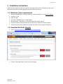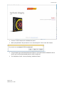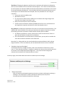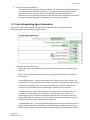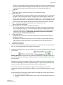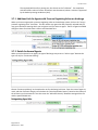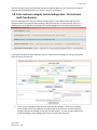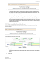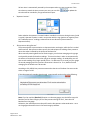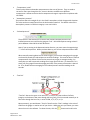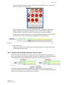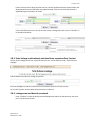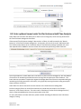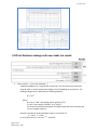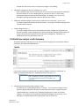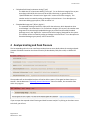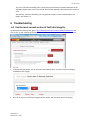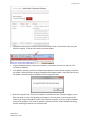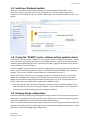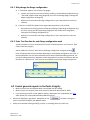
1
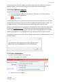
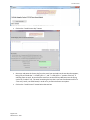
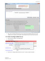
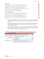
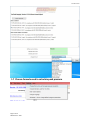
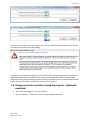
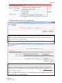
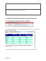
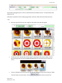
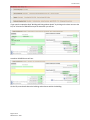
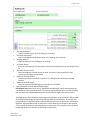
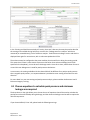
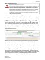
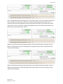
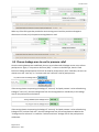
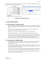
Operation Manual rev-2015-08-25 Software FanTestic Integrity (complying with ISO14520) Retrotec Inc. rev-2015-08-25 FanTestic Integrity Retrotec’s latest Enclosure Integrity Test software Calculation of agent hold time or extended discharge rate, and peak pressure with required vent area, based on measured or estimated enclosure leakage Venting calculator to determine size of required pressure relief vent even before leakage is measured Comprehensive, informative, customizable reports output to Microsoft Word Automatic updates over the Internet Calculations fully compliant with the ISO 14520 standard (2006 edition), and some previous editions Small and versatile data storage of results using an open XML format (fxml) Table of Contents 1 Installation instructions ................................................................................ 4 1.1 1.2 1.3 1.4 1.5 1.6 1.7 1.8 2 Calculators and reference data are in the Tools menu................................. 14 2.1 2.2 3 Minimum system requirements ................................................................................................... 4 Download FanTestic Integrity ....................................................................................................... 4 Start FanTestic Integrity ................................................................................................................ 7 Enter a license key ........................................................................................................................ 7 Select a testing standard to use .................................................................................................... 9 Change language for user interface (and generated reports) .................................................... 10 Choose formula used to calculate peak pressure ....................................................................... 11 Change parameters used for running the program – (advanced operation) ............................. 12 View design concentration values for agents ............................................................................. 14 Calculate Pressure Relief Vent needed for system design.......................................................... 15 Perform an enclosure integrity test ............................................................. 17 3.1 3.2 3.3 3.4 3.5 3.6 3.7 3.7.1 3.7.2 3.8 3.8.1 3.8.2 3.8.3 3.8.4 3.9 3.10 3.11 Set up Door Fan equipment ........................................................................................................ 17 Begin a new test in the software to record Door Fan test.......................................................... 17 Input background test information............................................................................................. 17 Test and technician information ................................................................................................. 18 Equipment ................................................................................................................................... 18 Enter building and enclosure details........................................................................................... 20 Enter Extinguishing Agent Information....................................................................................... 25 Additional Info for Agents with Pressure Regulating Valves on discharge ............................................28 Details for Aerosol Agents .....................................................................................................................28 Enter enclosure integrity test air leakage data – for Enclosure Hold Time Analysis .................. 29 Enter recorded data from a Door Fan test ............................................................................................30 Leakage area calculated from door fan test entries ..............................................................................33 Enter leakage results already calculated from a previous Door Fan test ..............................................34 Leakage area used directly as entered ..................................................................................................34 Enter optional Lower Leaks Test for Enclosure Hold Time Analysis ........................................... 35 Enter values from an optional Upper Leaks Test ........................................................................ 36 Calculate and see hold time analysis results .............................................................................. 36 3.11.1 Click the calculate button to see results ................................................................................................36 Page 2 of 55 ©Retrotec Inc. 2015 rev-2015-08-25 3.11.2 Graph the test data and results .............................................................................................................36 3.12 3.13 4 Analyse Venting and Peak Pressure ............................................................ 39 4.1 4.2 4.3 4.4 4.5 5 6.4.1 6.4.2 6.5 Use the most current version of FanTestic Integrity .................................................................. 48 Install your Windows Updates .................................................................................................... 50 If using the “ADMIN” version, software will not update to latest .............................................. 50 Changing Range configurations .................................................................................................. 50 Why change the Range configuration....................................................................................................51 Enter Test Fan data for each Range configuration used ........................................................................51 Cannot generate reports in FanTestic Integrity .......................................................................... 51 Ask for Support ........................................................................................... 52 7.1 7.2 7.2.1 7.2.2 7.2.3 7.2.4 7.3 8 Save results to a test file (.fxml).................................................................................................. 46 Save results to a different file ..................................................................................................... 46 Open a test file (.fxml) ................................................................................................................ 47 Generate report documents (MS Word) from test data ............................................................ 47 Printing ........................................................................................................................................ 47 Troubleshooting.......................................................................................... 48 6.1 6.2 6.3 6.4 7 Choose equations to calculate peak pressure and minimum leakage area required................. 40 Enter air leakage data used to determine leakage area of PRV ................................................. 41 Choose leakage area to use for pressure relief .......................................................................... 43 Venting and Peak Pressure Analysis test results......................................................................... 44 Graphic showing acceptable range of leakage for enclosure ..................................................... 45 Use the Test results..................................................................................... 46 5.1 5.2 5.3 5.4 5.5 6 Total Enclosure Leakage and Lower leaks test results ................................................................ 37 Hold time analysis results Summary ........................................................................................... 38 Before you ask, update your software........................................................................................ 52 What information to send .......................................................................................................... 52 Find the Log File to Upload ....................................................................................................................52 Find the Test File to Upload ...................................................................................................................53 Find the Settings File to Upload .............................................................................................................53 Create a picture of the error to Upload .................................................................................................53 Where to send the information .................................................................................................. 54 Get a License ............................................................................................... 55 Page 3 of 55 ©Retrotec Inc. 2015 rev-2015-08-25 1 Installation instructions While FanTestic Integrity software may identify clean agent peak pressure and hold time risks, use of this software does not in any way guarantee the elimination of those risks. 1.1 Minimum system requirements Microsoft Windows O/S: XP (SP2 or greater) or newer (Vista/7/8) –current with all updates Processor: 1 GHz RAM: 512 MB Disk space: 600MB (32-bit) or 1.5 GB (64-bit) Microsoft Word: 2007/2010+ (or Word 2003 with 2007 support add-in) Internet connection with Microsoft Internet Explorer (for automatic software updates) .NET 4.0 framework (will update automatically with the FanTestic Integrity installation) 1.2 Download FanTestic Integrity Go to: http://www.retrotec.com/support/software-downloads Click the “Download” button next to FanTestic Integrity Page 4 of 55 ©Retrotec Inc. 2015 rev-2015-08-25 Click the “Install” button on the window that opens. When prompted with “Do you want to run or save setup.exe?” click on the “Run” button. If not prompted, go to the Downloads menu option on your web browser and double-click on the file you have just downloaded (which is called “setup.exe”). The “Application Install – Security Warning” window will open: Page 5 of 55 ©Retrotec Inc. 2015 rev-2015-08-25 click on the “Install” button. If the User Account Control (UAC) asks for permission, you must give administrator permission for the software to install the USB driver. After installation, FanTestic Integrity will open on your desktop. Page 6 of 55 ©Retrotec Inc. 2015 rev-2015-08-25 The first time you run FanTestic Integrity, you need to make some choices about how you will use FanTestic Integrity – access from the “Settings” menu as described in the next sections. 1.3 Start FanTestic Integrity There are two ways to start the program: Click on Windows “Start Menu” “All Programs” ”Retrotec” “FanTestic Integrity”, or click the FanTestic Integrity icon on your desktop. FanTestic Integrity (FTI) will run in demo mode with full functionality for 60 days after you first install. Once the demo version expires, you will not be able to generate the MS Word reports or export your test data to MS Excel. You will still be able to enter test data and see the results on-screen. Obtain a license and instructions for activating the software with the license before your demo expires by contacting [email protected]. The license will be valid for the period of time specified for the license, and once the license expires, you will not be able to generate the MS Word reports or export your test data to MS Excel. You will still be able to enter test data and see the results on-screen. If your demo or license has expired you will see a dialog window similar to the following when you start FanTestic Integrity: 1.4 Enter a license key Open FanTestic Integrity, if not already open. Once in the program click “Settings” Then click “Enter license details”. Page 7 of 55 ©Retrotec Inc. 2015 rev-2015-08-25 Click on the “Install License Key” button then copy and paste the license key from the email you received into the text box that appears, being sure to include the “===START_KEY===” and “===END_KEY===” portion of the key. If selecting from an email, be sure that the email has not inserted any odd items into the string, such as an “emailto” link. The email containing the key that is sent out from Retrotec will be a “Text only” email, not HTML based, in order to try to minimize license corruption. Click on the “Install License” button below the text box. Page 8 of 55 ©Retrotec Inc. 2015 rev-2015-08-25 Next, select a standard, and then fill in the user name and email address and then click “OK”. “Software user’s company” will be filled in automatically from the license that was entered. 1.5 Select a testing standard to use Open FanTestic Integrity, if not already open. Click on Settings: then click on “Change Standard used for new tests” to open the options window. Page 9 of 55 ©Retrotec Inc. 2015 rev-2015-08-25 Next, select a standard from the list, and then click “OK”. Normally you will choose the latest edition of the standard, but access to any available older versions is available in the lower part of the list. Changes can be made any time, but a new test file must be created for the new settings to be used. If a test file is already open when changes are made, you will be warned before the software creates the new file. If you do not let the software create a new file at that point, the old file will remain open with the old settings until you click “File” “New”, or use the “New test” link on the Test History menu, to create a new test using the new standard you chose. 1.6 Change language for user interface (and generated reports) Page 10 of 55 ©Retrotec Inc. 2015 rev-2015-08-25 1.7 Choose formula used to calculate peak pressure Page 11 of 55 ©Retrotec Inc. 2015 rev-2015-08-25 If you choose FIA or VdS, a warning dialog will open, but the choice will be respected after you click OK on the warning and OK on the original dialog. If you choose to use equations relying on peak mass flow rate to calculate peak pressure and minimum leakage required to relieve the peak pressure, entering smaller peak flow rates to override default values may result in under-estimating minimum venting area required. Such an under-estimation would lead to over-pressurization if a smaller than necessary vent is installed. 1.8 Change parameters used for running the program – (advanced operation) Open FanTestic Integrity if it is not already open. Click on “Settings” “Advanced - view or change program parameters” Page 12 of 55 ©Retrotec Inc. 2015 rev-2015-08-25 The dialog window opens with the “Basics” tab showing. “Basics” Tab Choose how automatic readings will be displayed on graphs – only applies to experimental use of automatic control (not yet implemented). Click on the “Application” tab to see the following selections: “Application” Tab For your information, displays the location of the FanTestic Integrity application on your computer, and where test results will be stored. You can turn detailed logging on or off. A new log will be created each day. Creating detailed logs is recommended, so you can send to [email protected] if you have a software problem. Create “Run as Administrator” shortcut – only needed for experimental debugging purposes, for use with automatic control of the DM-2 gauges. Page 13 of 55 ©Retrotec Inc. 2015 rev-2015-08-25 Click “OK” to exit the window and for changes to become effective, or Cancel if you were just viewing the current settings and do not wish to make any changes. 2 Calculators and reference data are in the Tools menu 2.1 View design concentration values for agents If you have ISO14520, 2006 edition or AS-ISO 14520 (2009 edition) or APSAD selected as the standard, the following window will open: If you have BS EN15004, 2008 edition selected as the standard, the following window will open: Page 14 of 55 ©Retrotec Inc. 2015 rev-2015-08-25 2.2 Calculate Pressure Relief Vent needed for system design To open the Venting Calculator, click on the Tools menu and choose the “Calculate Pressure Relief Vent needed for system design” menu option: Alternatively you can click on the “start venting calculator” button in the “Enclosure leakage design” expander interface: Page 15 of 55 ©Retrotec Inc. 2015 rev-2015-08-25 The venting calculator will open: Page 16 of 55 ©Retrotec Inc. 2015 rev-2015-08-25 You may wish to change to ISO14520 for the enclosure leakage standard: 3 Perform an enclosure integrity test 3.1 Set up Door Fan equipment The Door Fan system must be set up properly into the doorway of the enclosure to perform an Enclosure Integrity Test. For instruction on how to set up a Door Fan system, refer to the QuickGuide-Blower Door, which will be downloaded from the Retrotec website: (http://www.retrotec.com/manuals-guides/QuickGuide-Blower%20Door-QG301.pdf) You can also refer to the Operation Manual-Air Leakage Test Systems: (http://www.retrotec.com/manuals-guides/Manual-Door%20Fan%20Operation.pdf) Prior to the test, achieve the minimum and maximum induced pressures in the enclosure desired for your test, to ensure that your fan is on a suitable Range configuration. It is possible that you will have to change Range configuration during a test. For more information on changing Range configuration, see section 6.1. 3.2 Begin a new test in the software to record Door Fan test To start a new test click on “New test” at the top of the test history, or use “File” “New”. Make sure “New Test” at the top of the test history is followed by “ISO 14520”. If not, in the menu, click “Tools” “Settings“ “Change Standard” and choose the radio button for the edition of the ISO 14520 standard to use in calculating results for the test. 3.3 Input background test information Enter your data into all the yellow boxes – the yellow boxes indicate required entry items without default values. They will turn green after entry. Click the button once all the data is entered in order to view the results; gray boxes show the calculated results and are not editable. The user input is split up into several different sections which are detailed in the following sections. Page 17 of 55 ©Retrotec Inc. 2015 rev-2015-08-25 3.4 Test and technician information The second expanding tab in the user interface provides places to enter details about who performed the test, and shows details of the file being used to save the test information, the standard being complied with (ISO in this case), and details of the software license: If you open the expander titled “Test and Technician Info” by clicking on the down arrow to the left, you will see: The following data entry options are available on the left side: Information entered for the test technician will be saved for new tests, and is only editable if the software license is not expired. “Witness name, company” Enter the name of the witnessing authority and the company “Witness phone, e-mail” Enter the contact number and email for the witnessing authority 3.5 Equipment The third expanding tab in the user interface provides places to enter details about the equipment used to perform the test: If you open the expander titled “Equipment” by clicking on the down arrow to the left, you will see: Page 18 of 55 ©Retrotec Inc. 2015 rev-2015-08-25 The number of gauge/fan pairs in the list is determined by the software license. An expired license will allow only one. Information entered for the fan model, gauge model, and serial number will be saved for new tests. “Fan” Select the type of fan that you are using from the picture menu that will appear. To close the “Fan” selection box, click the picture matching the fan you are adding. The fan picture background color will be added highlighted when you are hovering over it with the cursor. If you are allowed to use more than one fan with your software license, you will have an “Add a Test Fan” button on the left side. Click the Page 19 of 55 ©Retrotec Inc. 2015 button once for each of the rev-2015-08-25 fan/gauge pairs you would like to add. You can use the or you can use the button to delete a fan/gauge pair, button to make that fan/gauge pair the primary (placing it as “#1” Fan). “Gauge” Select the gauge type (DM32, DM32-20A, DM-2, DG-700) from the drop down list. You must select the gauge model for FanTestic Integrity to compute results. “S/N“ to enter the serial number of each of the fan and the gauge The first S/N input is to the right side of the “Gauge” input and is to record the serial number of the gauge. The serial number of a Retrotec DM-2 gauge can be found on a gray label at the base (on the bottom end) of the gauge, as well as in the gauge splash screen in the top left corner immediately after turning it on The serial number for a Retrotec DM32 gauge can be found on a black and white label on the back of the gauge, and on the top of the splash screen when the gauge powers on. In the DM32 Settings menu, the serial number can be found in the “Firmware” option. The second S/N input is to the right side of the “Fan” input and is to record the serial number of the fan. If you see “Demo” as the serial number in this drop-down, then you are running a demo license, or you have chosen a fan model which you do not own. You need to choose the model of fan that you own for your fan serial number to show up in the drop down. FanTestic Integrity licenses are specific to particular fans. The serial number of Retrotec Door Fans can be found on a gray label on the Fan Top of the device. “Location” Enter the physical location of the fan. “Fans last calibrated” and ”Gauges last calibrated” Enter the calibration dates of the fan and gauge 3.6 Enter building and enclosure details The fourth expanding tab in the user interface provides places to enter details about the enclosure being tested, the agent and amount of agent being used, calculation method for hold time, and conditions during hold time: Page 20 of 55 ©Retrotec Inc. 2015 rev-2015-08-25 If you open the expander titled “Building and Extinguishant details” by clicking on the down arrow to the left, for all variants of ISO14520 except the Australian you will see: Australian ISO14520 users will see: On the left, enter details about the building and enclosure within the building: Page 21 of 55 ©Retrotec Inc. 2015 rev-2015-08-25 “Building description” Enter a brief description of the building you are testing. “Enclosure Description” Enter a brief description of the enclosure in the building you are testing. “Building Address” Enter the address of the building you are testing. “Customer details” Enter the name and contact information of the person/company that you are doing the test for. “Elevation above sea level” Enter the building’s elevation above sea level. This value is used to perform a small correction to the agent concentration. “Maximum flooded volume” Calculate and enter the enclosure volume as it is defined in ISO 14520 (net protected volume). “Maximum flooded height” Enter the maximum flooded height as it is defined in ISO 14520 “Over-ride default value of 90% of flooded height” Checking the box permits entry of any “Required protected height” which would typically be “the elevation of the protected hazard”. By doing so would mean you were not fully compliant with the letter of the Standard but there are reasons why this might make sense; read on. The 2006 version of this Standard requires agent concentration to be held at 10%, 50% and 90% of the total flooded height for Descending Interface Hold Time calculations. Check with your local jurisdiction to determine what is required because many do not require this conservative approach. Both the 2000 version of ISO and the version about to be released in 2015 require: “At the end of the hold time, the extinguishant concentration at the elevation of the protected hazard shall be not less than 85% of the design concentration”. Page 22 of 55 ©Retrotec Inc. 2015 rev-2015-08-25 In practice, using 90% of the total flooded height for Descending Interface Hold Time calculations will reduce hold times by 50 to 75%. This forces enclosures to be 2 to 4 times tighter to pass which is often difficult, expensive and/or impossible. For this reason, many jurisdictions do not adhere to this requirement but some do. Continual Mixing is often a way to comply with the Standard because mixing maintains the same concentration at all heights making the 90% requirement irrelevant. This is often the only way the enclosure will pass the required hold time because mixing will always yield longer hold times. If the Initial Concentration is greater than the Design the hold time will increase even more. For example, if the Initial is 40%, the Design is 40% and the Minimum is 34% and the hold time is 7.1 minutes, then, if the Initial is increased to 44%, the Design is still 40%, the Minimum is still 34% but the hold time increases to 11 minutes. When increasing the Initial, the Design stays the same but the hold time increases. Do NOT make the common mistake of making the Minimum 85% of the Initial which would nullify the effect of adding extra agent. Instead, always make the Minimum 85% of Design. In order to comply using continual mixing, there must be mechanical or thermodynamic effects during the hold time that would ensure Continual Mixing does occur. Fortunately, these conditions are often present when dedicated HVAC is left running during the hold time or where hot equipment will cause mixing due to convection or where an extended agent discharge is used. Our guidance is to follow the requirements of the AHJ or to continue with past procedures. This software will make calculations in any way you choose but the operator may want to consider the following comments to provide a context should a decision path be needed. 1. If a definitive procedure is in place, continue with it until the new version of ISO is in place that will eliminate the 90% requirement. 2. The vast majority of tests done worldwide and future versions of all standards will not require protection to a mandatory 90%, so over-riding this default is a reasonable action. “Required protected height” If “Over-ride default value of 90% of flooded height” checkbox is checked, enter the minimum protected height. This height is usually measured to the top of the equipment you are trying to protect. If not, FanTestic Integrity will calculate 90% of the flooded height and enter this automatically for you. “Over-ride (He) calculation” Checking the box over-rides the He calculation and instead predicts the time it would take for the agent mixture to fall to the Minimum protected height, Hp. Using Hp assumes the interface has no thickness and will make your test non-compliant but there may be reasons you want to do this which are explained under, “Our guidance”. The ISO 2006 Edition of this Standard requires an equivalent interface height, He, be calculated in order to reduce hold times to allow for the development of a Wide Interface that was theorized to occur. He is only used in Descending Interface calculations where no Continual mixing occurs. Page 23 of 55 ©Retrotec Inc. 2015 rev-2015-08-25 The effect of allowing the software to perform the He calculation will reduce the hold time by 20% for inerts and about 35% for halocarbon chemical agents. This is done to make allowance for the formation of a theoretical Wide Interface that would reduce concentrations in the center of the interface below the Minimum. Since the Wide Interface was demonstrated not to occur and changes to the Standard have been accepted, there are precedents for over-riding the calculation: 1. He was not used in the 2000 version 2. NFPA does not use He 3. The new version of ISO will have a different He calculation that will give longer hold times but not as long as not using He at all. 4. Many countries do not use the He calculation. 5. Previous versions of Retrotec software (CA2001) did not force an He calculation but it was supplied as a separate calculation for those who wanted to use it. Our guidance is to follow the requirements of the AHJ or to continue with past procedures. This software will make calculations in any way you choose but the operator may want to consider the following comments to provide a context should a decision path be needed. 1. If a definitive procedure is in place, continue with it until the new version of ISO is in place that will reduce the impact of He calculations. 2. If the He calculation has not been done in previous tests, you may wish to consider the over-ride to make the evaluation on the same basis. Note that if He is being used now, the new Standard that may be published in 2015, will give longer hold times. If He is not used now, the new Standard will result in shorter hold times. “Equivalent sharp interface height” A calculated value for the height of interest, used in the calculations of hold time in certain cases. If “Over-ride (He) calculation” checkbox is checked, the value in this box will be the same as the value in the “Required protected height box”. If not, then FanTestic Integrity will calculate the He and enter this calculated value in the box. On the top right, enter details about the enclosure conditions prior to discharge “Design temperature” Enter the minimum anticipated temperature that the enclosure could experience during a discharge. This temperature is used to calculate the lowest (worst case) Initial Concentration that could be achieved after a discharge. Page 24 of 55 ©Retrotec Inc. 2015 rev-2015-08-25 “Bias pressure during hold time” Enter the bias pressure during hold time conditions, as it is defined in ISO 14520 (measured or estimated bias pressure during hold time). If the bias pressure at discharge is greater than 25% of the Initial column Pressure, it must be reduced. Even though this IS a requirement, many installations have massive bias pressures and will still hold concentration but require “engineering judgment” that Retrotec can assist with if needed. 3.7 Enter Extinguishing Agent Information On the bottom right of the “Building and Agent details” expander tab, enter details about the extinguishing agent and hold time calculation method: “Calculate Hold time result using:” Select which type of fire suppression system model will be assumed for calculation of the hold time. There are three options, defined according to how the agent behaves after a discharge in the enclosure: “Descending Interface “– Agent is discharged at near-ceiling level into the enclosure. An ‘interface’ with a constant concentration (known as the Initial Concentration) descends from the discharge level as gas leaves the enclosure through leaks. The time it takes for this ‘interface’ to reach the Minimum protected height is defined as the “hold time”. “Continuous Mixing” – Agent is discharged at near-ceiling level into the enclosure. Fans circulate gas throughout the room, resulting in a uniform agent concentration. This concentration begins at Initial Concentration and reduces until it eventually reaches the specified Minimum Concentration. The time it takes for the Initial Concentration to reach the Minimum Concentration is defined as the “hold time”. “Extended Discharge “ – An initial agent discharge achieves the Design Concentration over a short period of time, which is followed by a second Extended discharge rate (actual) from another supply of agent in order to maintain at least the Design concentration for a desired Page 25 of 55 ©Retrotec Inc. 2015 rev-2015-08-25 duration. By measuring the enclosure leakage, the agent loss rate can be calculated, which is calculated as the Extended discharge rate (required). The Enclosure Integrity Test passes if the Extended discharge rate (actual) is greater than the Extended discharge rate (required). “Agent” Select which agent is used for the enclosure’s fire suppression system. “Agent quantity by” Enter the agent quantity and choose whether you are entering agent mass or just entering the agent’s initial concentration directly. The agent mass can be found on a label on the bottles containing the agent; if you have both the agent mass from the bottle and an initial concentration specification, it is advised to use the agent mass. Users of INERGEN or other IG-541 can enter Agent quantity by volume since they may know the quantity as volume. “mass” – calculated and displayed if agent quantity is not entered as mass Mass of agent being discharged. “Initial concentration” [% volume] - calculated, not entered The initial concentration, as a percent of volume, of agent in the enclosure immediately after a complete discharge (i.e. the concentration of agent at the beginning of the Hold time), calculated based on the agent mass, and enclosure details. Initial concentration is expressed as a percentage. A value will be calculated once you have entered both a quantity and the “Maximum flooded volume”. “Design concentration “ The agent design concentration, which will be specified by the fire protection engineer designing the system. For reference, the question mark help icon next to this item brings up a table containing values for design concentration listed in your standard, same as the Tools menu item described in section 2.1. “Minimum concentration” The minimum concentration is the final concentration in the enclosure at the end of the hold time. It is set by default to 85% of the “Design concentration”. For Australian ISO14520 users, the user can choose to over-ride the default value for Minimum concentration: Checking the box allows you to enter any “Minimum concentration” and select a value that is less than 85% of design. By doing so would mean you were not fully compliant with the letter of the Standard. Standards require that, at the end of the hold time, the agent concentration must be greater than 85% of the Design at the Minimum protected height. To place this in perspective, most countries do adhere to this requirement but some do not, notably Australia. The Initial concentration must be equal to or greater than the Design. In cases Initial concentration is greater than the Design, the Minimum must still be based on Design, not the Initial. Entering a Minimum concentration smaller than 85% of Design will increase retention time if: 1. There is Continuous Mixing, or 2. Descending interface is chosen and He is used. If He is not used then there will be no change. Page 26 of 55 ©Retrotec Inc. 2015 rev-2015-08-25 In the case of “Continuous mixing”, the same items are displayed: In the case of “Extended Discharge”, another value will be displayed: The “Planned extended discharge rate” value will also be displayed The entered value represents the planned extended discharge rate for the existing system. The value can be found from the fire suppression system’s specification sheet. For an Extended Discharge situation to pass, the “Planned extended discharge rate” must be greater than the calculated “Required extended discharge rate” in the results section. The required rate is calculated based on how much leakage is entered for the enclosure. “Specified hold time” Page 27 of 55 ©Retrotec Inc. 2015 rev-2015-08-25 The required Hold time for a passing test, also known as the “hold time”. For compliance with ISO 14520 a value of at least 10 minutes must be entered, unless a variance is approved by the Authority Having Jurisdiction (AHJ). 3.7.1 Additional Info for Agents with Pressure Regulating Valves on discharge When you have an agent with a pressure regulating valve on the discharge system, click on the “using a pressure regulating valve” check box. This will remove any agent that was previously selected and you may get a calculation warning which you can ignore until you enter an agent. The list of agents available changes to those for which there is data to calculate hold time. 3.7.2 Details for Aerosol Agents When you select Aerosol as an agent, the type of discharge may revert to “select a type” because the type can only be “Continuous Mixing”. Choose “Continuous Mixing” as the method to use for calculating hold time. Enter the mass of agent as usual, and then FanTestic Integrity will calculate the “Initial Application Density” based on the volume of the enclosure you have entered. You then enter the “Minimum Density” allowed to extinguish the fire and the specified hold time. Page 28 of 55 ©Retrotec Inc. 2015 rev-2015-08-25 FanTestic Integrity cannot calculate peak pressure for Aerosol agents, so the “Peak Pressure Analysis” expander tab will be disabled when you choose “Aerosol” as the agent. 3.8 Enter enclosure integrity test air leakage data – for Enclosure Hold Time Analysis The fifth expanding tab in the user interface provides places to enter details about the Enclosure Leakage by door fan test performed according to ISO 14520 Annex E, and the pass/fail result from comparing the calculated hold time based on the tested leakage area with the specified hold time: If you open the expander titled “Hold time analysis: Total Enclosure Leakage” by clicking on the down arrow to the left, you will see: There are two methods to determine the total enclosure leakage – either enter recorded pressure/flow values from a door fan test performed on the enclosure and have FanTestic Integrity calculate the leakage (“Enter Door fan test values”), or enter a known value for the enclosure leakage (“Enter leakage results from a previous door fan test”). Page 29 of 55 ©Retrotec Inc. 2015 rev-2015-08-25 If “Enter Door fan test values” is selected, you are choosing to use the “Induced Pressures” and “Flows” from a door fan test to calculate Equivalent Leakage Area and the results. This method of entry is selected by default. Alternatively, if “Enter leakage results from a previous door fan test” is selected, you are choosing to enter an “Equivalent Leakage Area” value directly, for instance if you just want to get an idea of what the results would be if this number were true. This is used if you want to experiment with different leakage sizes just to see how the results vary. If this value is entered, you do not have to enter “Induced Pressures” and “Flows” for FanTestic Integrity software to calculate results. 3.8.1 Enter recorded data from a Door Fan test Choose, or leave the default choice as, “Enter Door Fan test values” as the selection under “Total Enclosure Leakage”: And the data entry section will then look like: “Test date” The date the test was started is automatically filled in with the current date in YYYY-MM-DD format “Start time” Page 30 of 55 ©Retrotec Inc. 2015 rev-2015-08-25 24 hour time is automatically entered by the computer when you start a new test. If this time does not match the time you start your test, you can click time that will be recorded in your generated test report. to update the “Operator location” Select whether the operator is located inside or outside the enclosure during the test (inside is typical). Operator location is used in conjunction with the sign (positive or negative) from the “Induced pressure” readings, to determine the test direction (Pressurization or Depressurization). “Bias pressure during fan test” The pressure before a pressurization or depressurization test begins, while the fan is sealed and turned off. Bias pressure values correct the induced pressure readings from pressures other than what is induced by the airflow of the Door Fan. When manually entering data into FanTestic Integrity, set the time averaging on the gauge to at least 60 seconds for baseline readings. This must be done in order to compensate for the effects of wind and to ensure that you get an average reading. On windy days you will have to take readings for a longer period of time. To determine if it is windy, set your gauge 25 second averaging and if the pressure fluctuation is above 2 Pa. If so, double the time averaging for the baseline to 120 seconds. According to ISO 14520, bias pressures measured at the time of the Door Fan test must be within a range of ±3 Pa. If the value entered is outside these bounds, a warning will result similar to the following: Note: If you’ve used the [Baseline] function on a Retrotec gauge, you should first copy this Baseline into FanTestic Integrity as the “Bias pressure during fan test”, then clear the Baseline from the gauge. Otherwise, the induced pressure value will have the bias pressure subtracted twice – once on the gauge and another time in FanTestic Integrity software. Page 31 of 55 ©Retrotec Inc. 2015 rev-2015-08-25 “Temperature, initial” These are the indoor and outdoor temperatures at the start of the test. They are used to correct for flow rates through the fan, since air densities are different at different temperatures. Airflow correction due to temperature change is required for compliance with ISO 14520. “Atmospheric pressure” The pressure due to the weight of air in the Earth’s atmosphere, which changes with elevation. This value can be accurately found from the local weather network. The default value of the Atmospheric pressure in FanTestic Integrity is set at 101.3 kPa. “Induced pressure” The pressure in the enclosure as a result of the airflow induced by the Door Fan. Induced pressures are read from the gauge as “PrA”. ISO 14520 requires testing at least 5 points between 10 and 60 Pa in both directions. Note: If you are testing in the Depressurization direction, you must enter the negative sign, “-“ in front of the pressure. When you have done so, you will see a Depressurization label: When manually entering data into FanTestic Integrity, set the time averaging on the gauge to at least 20 seconds for induced pressure and flow readings. This must be done in order to compensate for the effects of wind and to ensure that you get an average reading. On windy days you will have to take readings for a longer period of time. To determine if it is windy, set your gauge 25 second averaging and check if the pressure fluctuation is above 2 Pa. If so, double the time averaging for the induced pressure and flow readings to 40 seconds. “Test Fan” “Test Fan” data can be input as Fan Pressures, in units of Pa, (which allows FanTestic Integrity to calculate air flow rates through the Door Fan) or can be entered manually as air flow rates through the Door Fan, in units of CFM, m3/h, m3/s, or L/s. Most commonly, you would enter “Test Fan” data from the “Flow” readings in the units of CFM from the gauge, or another unit of your choice. Whichever unit you choose, you must select the unit in the software. To select the unit, click the Page 32 of 55 ©Retrotec Inc. 2015 button and scroll to the rev-2015-08-25 bottom of the pop up window. There you will see the choices of Flow units, click the unit you will be using to enter Flow values: You can also enter the Fan Pressures by entering the “PrB” readings from the Retrotec gauge, along with the Fan Range configuration in use, so that FanTestic Integrity can calculate the Flow. When Fan Pressures are entered, you must select the Range Configuration installed on the Door Fan. To select the Range configuration, click the button and click the picture of the Range configuration in the popup display. “Corrected flow rate” displays the entered or calculated air flow rates through the Door Fan required to achieve the indicated Induced Pressure. 3.8.2 Leakage area calculated from door fan test entries Results are displayed individually for each of Pressurization and Depressurization data sets. If both “Pressurization” and “Depressurization” data sets are completed, the results will appear in a combined Results section, showing the average of the results from each data set. The reason behind performing an air leakage test in both directions is to average out any potential pressure problems there might be in one direction over the other (like blowing open a damper in one direction, but sucking it closed in the other). Page 33 of 55 ©Retrotec Inc. 2015 rev-2015-08-25 If there is bias pressure during the door fan test, it will be applied to both the pressurization and depressurization sets and the values may appear skewed if you do not realize that the bias is applied during the calculation of results: If the entered bias pressure or any of the other values is changed, be sure to press “Calculate” to re-calculate the Results: 3.8.3 Enter leakage results already calculated from a previous Door Fan test Choose “Enter leakage results from a previous Door Fan test” as the selection under “Total Enclosure Leakage”: And the data entry section will change to look like: Enter the leakage area and the n value that was calculated in the previous Door Fan test. Set n as 0.5 if you do not know what the previous test n value was. 3.8.4 Leakage area used directly as entered Press “Calculate” to take the directly entered leakage area value from the data entry area, and put it into the results section. Page 34 of 55 ©Retrotec Inc. 2015 rev-2015-08-25 3.9 Enter optional Lower Leaks Test for Enclosure Hold Time Analysis Lower leaks tests are either Flex Duct tests or Plastic on the Ceiling tests, which are only performed if the Total Enclosure Leakage test has failed. If the entered “Total Enclosure Leakage” data results in a failure, this will be stated in the “Results Summary” of the Total Enclosure Leakage test. At that point, the user clicks on the “Add Lower leaks Test” button at the bottom of the “Hold time analysis: Total Enclosure Leakage” expander tab, and a new expander will be added for the user to enter the results from performing a lower leaks test. The test procedure for a lower leaks test is the same as a Total Enclosure Leakage test, with the addition of some form of neutralizing the leaks that are occurring from the upper part of the enclosure. The lower leaks test procedure is required to negate the leakage above the enclosure’s suspended ceiling by neutralizing the ceiling space (with a Flex Duct), or by physically covering the entire ceiling space (with sheets of plastic air barrier). Lower leaks Test data is entered in the same manner as the Total Enclosure Leakage data. FanTestic Integrity factors in results from both tests to provide new test results in the “Results Summary” of the Lower leaks test. The main result is calculation of a value for the leakage fraction F, which is otherwise defaulted to the most conservative value of 0.5. For more information on Lower leaks tests, please consider attending the Retrotec Level 3 Enclosure Integrity Training. Page 35 of 55 ©Retrotec Inc. 2015 rev-2015-08-25 3.10Enter values from an optional Upper Leaks Test “Upper Leaks” tests are similar to the Lower Leaks test, but you would instead temporarily seal the Lower Leaks and test leakage above. Upper Leaks Test Data is entered in the same manner as the Lower Leaks or the Total Enclosure Leakage tests. FanTestic Integrity factors in a new lower leakage fraction, F, by using the leakage results from the Total Enclosure Leakage, Lower Leaks, and Upper Leaks test to provide new test results in the “Results Summary” of the Upper Leaks test. For more information on Upper Leaks tests, please consider attending the Retrotec Level 3 Enclosure Integrity Training. 3.11Calculate and see hold time analysis results Results are displayed in gray boxes. Remember to click calculate and display the updated results. if any data is changed, in order to 3.11.1 Click the calculate button to see results Always click calculate before generating a report, or recording values any other way. 3.11.2Graph the test data and results FanTestic Integrity provides a graphical display of Induced pressure and fan flow readings by clicking the button. The graphs will come up in a separate window that can be opened or closed at any time. Page 36 of 55 ©Retrotec Inc. 2015 rev-2015-08-25 3.12Total Enclosure Leakage and Lower leaks test results “Flow constant” , k1 and “Flow exponent”, n A Building Leakage Curve is created after at least two “Test Fan” data points have been entered, which is used to estimate the leakage rate of the building at any pressure. The Building Leakage Curve is defined by the following equation: Q = k1 x P n where: Q is the air “Flow” rate through the fan (CFM or m3/h) k1 is the “Flow constant, (CFM/Pan or (m3/h)/Pan) P is the pressure difference between the inside and outside of the enclosure (Pa) n is the “Leakage exponent” Example: calculate the airflow needed to create a 5 Pa pressure if: k1 = 110.2 n = 0.702 Q, the airflow (at 5 Pa) = 110.2 x 50.702 = 341 CFM. Page 37 of 55 ©Retrotec Inc. 2015 rev-2015-08-25 It would take 341 CFM to cause a 5 Pa pressure change in this building. “Equivalent Leakage Area at 10 Pa” (EqLA) [cm2 or sq in] EqLA is defined as the area of a hole (in units of cm2 or sq in) in a thin panel that would leak the same amount of air as the building does at a pressure of 10 Pa. It most closely approximates physical hole sizes found in buildings - for example, a 2 inch by 3 inch rectangular opening would measure about 6 square inches of EqLA. “Maximum allowable leakage at 10 Pa that will maintain xx min hold time”, [sq in or cm2] The largest EqLA allowed by the specified hold time – any larger will require sealing and the enclosure will fail the test. “Lower leakage fraction”, F The Lower leakage fraction is the ratio between the Lower Leakage Area (LLA) and Total Enclosure Leakage. Lower leakage fraction can be calculated by dividing the EqLA from the Lower leaks test by the EqLA from the Total Enclosure Leakage test. Otherwise, it is defaulted to the most conservative value, 0.5. 3.13Hold time analysis results Summary The Results Summary indicates to the user if the Enclosure Integrity Test has passed or failed in compliance with ISO 14520 (2006 edition). If your test has failed, you need to seal up enclosure leakages to lower the “Hold time” or required “Extended discharge rate”, depending on what “Test type” it is. “Calculated hold time (descending interface)“ [min] The Hold time for a Descending Interface “Test type”. For an Enclosure Integrity Test to pass according to ISO 14520, this time must be at least 10 minutes, or greater than the “Specified hold time” entered in the “Extinguishing Agent Info” section of FanTestic Integrity. This number can be increased by sealing up leakages in the enclosure. For a description on Descending Interface type systems, refer to section 3.4. Page 38 of 55 ©Retrotec Inc. 2015 rev-2015-08-25 “Calculated hold time (continuous mixing)” [min] The Hold time for a Continuous Mixing “Test type”. For an Enclosure Integrity Test to pass according to ISO 14520, this time must be at least 10 minutes, or greater than the “Specified hold time” entered in the “Agent Info” section of FanTestic Integrity. This number can be increased by sealing up leakages in the enclosure. For a description on Continuous Mixing type systems, refer to section 3.4. “Extended discharge rate“ [lb/min, kg/min] The extended discharge rate that is required for the enclosure, which depends on how much leakage is in the enclosure. For an Enclosure Integrity Test to pass, this number must be greater than the existing Extended discharge rate, entered as the actual Extended discharge rate (in the “Agent Info” section of FanTestic Integrity), designed for the system. This number can be increased by sealing up leakages in the enclosure. For a description on Extended discharge type systems, refer to section 3.4. 4 Analyse Venting and Peak Pressure The last expanding tab in the user interface provides places to enter details about the venting and peak pressure calculations based on the chosen formula (as described by FSSA, FIA or VdS, or NFPA12 for CO2): The expander will not be enabled and you will not be able to open it if the agent has been chosen as Aerosol. See the document “Explaining Aerosol Calculations” online for details, also accessible from within the program: If you can open the expander titled “Venting and Peak Pressure Analysis” by clicking on the down arrow to the left, you will see: Page 39 of 55 ©Retrotec Inc. 2015 rev-2015-08-25 In the “Venting and Peak Pressure Analysis” section, there are 2 data sets that may be used to describe the venting area available during hold time, as well as the “Leakage area for enclosure” which was measured (or entered directly) in the “Hold time analysis- Total Enclosure Leakage” section and which is displayed here again for convenience, with its value extrapolated to 125 Pa. The enclosure must be configured to the same condition that it would be in during the venting period. This means that if there is some means of pressure relief other than enclosure leakage (via the PRV specified in the dropdown), it must be set to discharge mode. Once this is done, another door fan test is run and this new leakage area is used for peak pressure calculations. In some cases, the venting available with the chosen PRV will be different for a positive peak pressure than a negative peak pressure, so a separate dataset is provided to enter venting information for each direction. For more detail on vent area testing and peak pressure analysis, please consider the Retrotec Level 2 Enclosure Integrity Training. 4.1 Choose equations to calculate peak pressure and minimum leakage area required The drop down on the right allows you to choose the set of equations that will be used to calculate the peak pressure that will develop during discharge, and the minimum leakage area that will be required to relieve that pressure. If you choose NFPA12, FIA or VdS, please heed the following warnings: Page 40 of 55 ©Retrotec Inc. 2015 rev-2015-08-25 If you choose to use equations relying on peak mass flow rate to calculate peak pressure and minimum leakage required to relieve the peak pressure, entering smaller peak flow rates to override default values may result in under-estimating minimum venting area required. Such an under-estimation would lead to over-pressurization if a smaller than necessary vent is installed. 4.2 Enter air leakage data used to determine leakage area of PRV When “no pressure relief vent” is chosen in the “Pressure relief vent (PRV) type” drop down, venting area to relieve positive and negative peak pressure is calculated using “enclosure leaks only “ which is displayed in the “Leakage area for enclosure” data box. The “Leakage area for enclosure” is the leakage taken from the Total Enclosure Leakage section extrapolated to a standard reference condition of 125 Pa which is representative of conditions where most of the peak pressure will be relieved. In this case, the venting datasets are not used. When any of the other PRV types tare chosen, both venting datasets are used, the “Venting datasets express leakage area of:” drop down is used to indicate what was measured (or estimated) in the datasets. When any of the PRV types that provide venting in both directions (for positive and negative pressure) are chosen, both venting datasets are used. If the “Venting datasets express leakage area of:” drop down shows “enclosure and vent”, datasets contain data which resulted from measuring or entering an estimate of the leakage area of the enclosure and vent combined. For measuring the positive venting dataset, the enclosure would have been set up in a condition where dampers were fixed in the position they would assume under +125 Pa, and for the negative venting dataset, the enclosure would have been set up in a condition where dampers were fixed in the position they would assume under -125 Pa. Page 41 of 55 ©Retrotec Inc. 2015 rev-2015-08-25 If the “Venting datasets express leakage area of:” drop down shows “vent only”, datasets contain data which resulted from measuring or entering an estimate of the leakage area of the PRV itself. For measuring the positive venting dataset, the vents would have been fixed in the position they would assume under +125 Pa, and for the negative venting dataset, the vents would have been fixed in the position they would assume under -125 Pa. When any of the PRV types that provide venting only in the positive direction are chosen, only the positive venting dataset is used, and leakage area for negative pressure relief is assumed to be the “Total Enclosure Leakage”. When any of the PRV types that provide venting only in the negative direction are chosen, only the negative venting dataset is used, and leakage area for positive pressure relief is assumed to be the “Total Enclosure Leakage”. Page 42 of 55 ©Retrotec Inc. 2015 rev-2015-08-25 When any of the PRV types that provide the same venting area in both the positive and negative directions are chosen, only the positive venting dataset is used. 4.3 Choose leakage area to use for pressure relief Once the venting datasets are established, the user must indicate which leakage area to use to relieve peak pressure. Again, if “no pressure relief vent (PRV)” is chosen as the PRV type, then the Total Enclosure Leakage extrapolated to 125 Pa will be used for peak pressure relief. Otherwise, the user can choose to use the “vent only” or “enclosure and vent” values for relief of peak pressure. If the venting dataset is expressing the leakage of “vent only “and peak pressure is to be relieved using leakage of “vent only”, then the leakage area from the venting dataset is used directly as the leakage area for the peak pressure calculations. If the venting dataset is expressing the leakage of “vent only “and peak pressure is to be relieved using leakage of the “enclosure and vent”, then the leakage area from the venting dataset is added to the “Leakage area for enclosure” to create the “enclosure and vent” leakage area for the peak pressure calculations. Page 43 of 55 ©Retrotec Inc. 2015 rev-2015-08-25 If the venting dataset is expressing the leakage of “enclosure and vent “and peak pressure is to be relieved using leakage of the “vent only”, then the “Leakage area for enclosure” is subtracted from the leakage area from the venting dataset to create the “enclosure and vent” leakage area for the peak pressure calculations. If the venting dataset is expressing the leakage of “enclosure and vent“ and peak pressure is to be relieved using leakage of “enclosure and vent”, then the leakage area from the venting dataset is used directly as the leakage area for the peak pressure calculations. 4.4 Venting and Peak Pressure Analysis test results Separate results are calculated for positive peak pressure and for negative peak pressure. Calculations vary depending on the equation set chosen to use – FSSA, VdS, or FIA. The equation for this test is set in the drop down, and a default can be chosen from the Settings menu. Negative results are only provided where appropriate: for Halocarbon agents if FSSA or FIA equations are chosen and if leak to volume curve data exists for the agent. Page 44 of 55 ©Retrotec Inc. 2015 rev-2015-08-25 The summary details the predicted peak pressure, the required minimum leakage to keep the pressure under the specified enclosure pressure limit, and any additional vent area that will be required over what is being assumed to provide the leakage for peak pressure relief (vent only or enclosure and vent). The summary includes the following for each Peak pressure [Pa] The peak pressure that the enclosure is predicted to develop during the hold time, based on the leakage being used for positive pressure relief. “Leak to Volume ratio” (LVRpos, LVRneg) [sq in/1000 cu ft or cm2/m3] Used in the FSSA (and FIA for halocarbon) equations, peak pressure development during hold time is a direct function of the Leak to Volume ratio. The Leak to Volume ratio indicates how much leakage there is for a given unit of volume. “Leakage area of enclosure” [sq in or cm2] The leakage area of the enclosure alone, with the result extrapolated to a pressure of 125 Pa. “Leakage area of vent only” [sq in or cm2] The leakage area of the PRV alone, with the result extrapolated to a pressure of 125 Pa. “…… used for positive/negative pressure relief” [sq in or cm2] Lists the leakage area the user has chosen to be used for pressure relief, calculated based on the values in the venting datasets and the Total Enclosure leakage. It is used for the purpose of calculating Peak Pressure during hold time of the fire suppression system. This number is calculated based on the selection in the “For pressure relief use leakage area of” dropdown menu (refer to section 4.3). There can be a different leakage area used for the positive and negative direction since different agents have different pressure release characteristics. Generally, Halocarbon gases create a large negative Peak Pressure with smaller amount of positive Peak Pressure, whereas Inert gases usually create large Peak Pressure only in the positive direction. “Minimum leakage to relieve positive/negative pressure” [sq in or cm2] The smallest leakage area that will allow the peak pressure to stay under the specified enclosure pressure limit and maintain the structural integrity of the enclosure during hold time. “Additional vent area needed” [sq in or cm2] The Additional vent area needed is the calculated amount of leakage that needs to be provided, that does not currently exist based on the current settings. This additional leakage needs to be put in place so that Peak Pressure can be lowered to the point where the structural integrity of the enclosure is not compromised during agent hold time. The additional vent area needed is calculated by subtracting the “… area used for pressure relief” value from the “Minimum leakage to relieve pressure” value. 4.5 Graphic showing acceptable range of leakage for enclosure To see a graphic showing the allowable leakage range, click on the “Show ELA Graph” button below the Peak Pressure results. Leakage needs to be less than that required for hold time but more than that required to be under the allowed enclosure peak pressure limit. The thick blue line shows the acceptable range for the enclosure leakage during discharge. The green triangle marks the leakage measured for the enclosure only. If the green triangle is to the left of the Page 45 of 55 ©Retrotec Inc. 2015 rev-2015-08-25 range, then you need to add venting using a pressure relief vent. If the green triangle is to the right of the range, then you need to seal up the room. 5 Use the Test results 5.1 Save results to a test file (.fxml) When a new test file is created, it is automatically named based on the Standard used (ISO) and the date (yyyy-MM-dd) and time (HHmm) that the file was created, and it has a file extension of .fxml. For example, “ISO 2014-02-28 1642.fxml” would be the name of the file created at 16:42 (4:42pm) on the 28th day of February in the year 2014. When you click “File” “Save”, FanTestic Integrity stores test data into that file. Test files are normally saved on your local C: drive under [MyDocuments]\Retrotec\Tests. Test data can be automatically saved at periodic intervals by turning the Auto Save function on (“File” “Auto save?”). Note that if you change the location of the test file to a remote drive, and then remove the remote drive with FanTestic Integrity running and AutoSave on, the software will not be able to save the file to the remote drive anymore, and may report an error. 5.2 Save results to a different file FanTestic Integrity can store test data (“File” “Save As”), which creates a new test file with the same name as the current test file but with the current date (yyyy-mm-dd) and time (HHMM) added at the end. For example, using the original test file “ISO 2014-02-28 1642.fxml”, if we do a “File” “Save As” at 10:42am on the 3rd of March 2014, the new file will have the suggested file name: “ISO 2014-02-28 1642 [2014-03-03 1042].fxml”. The “SaveAs” function makes it convenient to save the original test and keep it intact, but have a second “Save As” copy in which to manipulate parameters without affecting the original test. The “SaveAs” copy of the file may be changed without affecting the original test data, but the two files are visually linked via the filename. Page 46 of 55 ©Retrotec Inc. 2015 rev-2015-08-25 5.3 Open a test file (.fxml) To open a previous test that has already been completed and saved, there are several options: The main screen for FanTestic Integrity can display previously completed tests in the “Test History” pane on the left hand side (with a photo of the building, if it was included when the test file was created). If you have this option turned on (“Test History” “AutoHide“ not enabled), the list will remain open on the left at all times. Click the name of the test file you would like to open. Go to: “File” “Open” and a pop-up Windows Explorer window will display all tests in the [MyDocuments]\Retrotec\Tests directory which have the file extension “.fxml”. Go to: “Test History” “Show“ – the left hand list of all saved tests will appear, the same as the one displayed on the opening screen for FanTestic. 5.4 Generate report documents (MS Word) from test data FanTestic Integrity includes a built-in template for reports generated from test data, for each of the supported Standards. To generate a report, select “File” “Generate Report (docx – MS Word)”. There are also buttons that you can click in the user interface for your convenience: one below the hold time results, and one below the venting and peak pressure results. The “Generate report” function will automatically create and open a Word document containing a report with the data from your test. These report files will be stored on your local Drive under [MyDocuments]\Retrotec\Reports. Once the Word document is open, you can print it directly. Because the report is created by copying a template document and replacing tags with the actual test data, reports are customizable in Microsoft Word with FanTestic Integrity Pro versions. ISO test reports are generated using the template called “ISO-en.docx” which will be located in the [MyDocuments]\Retrotec\Templates directory after you have created at least one report. If you have chosen the ISO2000 standard, the template used will be “ISO2000-en.docx. Users customize the report output by changing the text in the template file that is used to create the Word document, and as long as the tags remain somewhere in the template, test data will be output to the generated document. If you want to create a language specific report, to match the language you use in the user interface, you can translate the template and call it “ISO-xx.docx” where xx is replaced with the country identifier. Some templates are already provided in translation, and if so, they will automatically be chosen for you if you have changed the language to use in FanTestic Integrity. The report generation function is only available if you have a valid, non-expired license for FanTestic Integrity. If you do not have such a license, you will be limited to seeing results on the screen, and when you generate the .docx report file, it will only show a sample report. The sample report will not contain the results from the test you are viewing on the screen. 5.5 Printing FanTestic Integrity will print the data as-is: only what is on the interface screen. Go to “File” “Print”, and you can either generate a PDF document or print a paper copy using the printer functions in Windows. Page 47 of 55 ©Retrotec Inc. 2015 rev-2015-08-25 The “Print” function essentially prints a screen shot of the FanTestic interface with each of the expander sections open, even if you cannot see all of the expander information on the screen at once. Alternatively, and more effectively, you can generate a report from the data and print the report, see section 5.4 6 Troubleshooting 6.1 Use the most current version of FanTestic Integrity To determine the latest version, go to: http://www.retrotec.com/support/software-downloads and click on the “Is your software up to date?” button beside the “Testing and Reporting Software” title: In the window that opens, click on the down arrow beside “Any” and select FanTestic Integrity instead then click “Apply”. A list of the versions of FanTestic Integrity will be shown, with the latest version at the top: Page 48 of 55 ©Retrotec Inc. 2015 rev-2015-08-25 Compare the online version number to the version number shown in the title bar when you open FanTestic Integrity. If they do not match, you need to update. To get the updated version, ensure your computer is connected to the internet, and click “File” ”Check for Updates”. If an update is available, you will be notified and prompted to restart FanTestic Integrity to perform the update. Starting FanTestic Integrity will download the update installer, and prompt you to start the update. Once the update is installed, FanTestic Integrity will start. Note that using the “File” ”Check for Updates” can declare that your FanTestic Integrity is up to date even when it is not in the following circumstances: your computer is not connected to the internet, you clicked “Skip update” when it was offered at any point, or you are using the “ADMIN” version of the software. This check for updates is a feature of the Click-Once installer technology used for installing the software, not FanTestic itself. Page 49 of 55 ©Retrotec Inc. 2015 rev-2015-08-25 6.2 Install your Windows Updates Make sure all the important and optional updates are installed for Microsoft Windows. This is particularly important for older versions such as Windows XP. FanTestic Integrity expects to the computer to have installed the .NET 4 Framework, XML support, and a Windows Installer version 3.0 or greater. 6.3 If using the “ADMIN” version, software will not update to latest To determine if you are using an “ADMIN” version, check for the word “ADMIN” in the title bar. This will only be the case in very few circumstances, as the “ADMIN” version is a specific fix for problems some computers with limited privileges have in connecting to the DM-2 gauge for automatic control, which is not yet available in FanTestic Integrity. If you see “ADMIN” in the title bar of your FanTestic Integrity while it is running, you should uninstall the version you have installed using the control panel, and DELETE ALL DESKTOP SHORTCUTS to FanTestic Integrity. Then you can re-install from the website link, as described in section 1.2. You will not lose your license key or any settings if you do this uninstall and reinstall. If you actually need to use the ADMIN shortcut which is only needed if you have trouble connecting to your DM-2 gauges for the automatic testing and have determined that the error is “Error 5: Access Denied”, then you will need to carry out the procedure to generate the ADMIN shortcut. Note that using the “File” ”Check for Updates” can declare that your FanTestic Integrity is up to date even when it is not if you are using the “ADMIN” version of the software. This is a feature of the Click-Once installer technology used for installing the software. 6.4 Changing Range configurations It becomes necessary to change Range Configurations during a test due to fan pressure too low (occurs when there is not enough flow through the fan) or the inability to reach a pressure target (occurs when fan speed is at 100% but you cannot reach the desired induced pressure). NOTE: it is recommended that the tester induce pressures over the full range of pressures desired to be tested (e.g.10 and 60 Pa) prior to performing the test, to ensure that one Range configuration can satisfy all pressures, and avoid changing Range configurations. Page 50 of 55 ©Retrotec Inc. 2015 rev-2015-08-25 6.4.1 Why change the Range configuration a) If “TOO LOW” appears as the Flow on the gauge: Increase Fan Pressure (restrict the flow) by installing a smaller Range configuration (e.g. “TOO LOW” appears when using Range C8, put in two more Range plugs to change the Range configuration to Range C6). Make sure to record the new Range configuration in your notes/test form and in the software. b) If the fan is at 100% fan speed but the target induced pressure is not reached: Decrease Fan Pressure (increase the flow) by installing a larger Range configuration (e.g. the fan is running at 100% speed using Range plate C8, remove the C Range plate, leaving the fan on Range configuration B). Make sure to record the new Range configuration in your notes/test form, ad in the software 6.4.2 Enter Test Fan data for each Range configuration used Transfer the data from your notes/test form into the “Induced pressure” and “Test Fan” data fields in FanTestic Integrity. Add an additional “Test Fan” data set for each Range configuration change by clicking . Enter the appropriate Fan Pressure data depending on which Range configuration was used. In the example below, the first three Induced pressures were achieved with Range plate C8; the next three Induced pressures required a smaller Range plate C6, and the Fan Pressure data are therefore on a different line, since each line corresponds to a particular Range configuration. 6.5 Cannot generate reports in FanTestic Integrity Make sure you have an unexpired demo or purchased license installed Make sure you are using the most recent version of Microsoft Word (2007 or 2010) If you are using an earlier version (2003 or earlier), download a free compatibility pack here, which allows you to open/edit/save Word 2007 documents. Results are displayed in gray boxes. Remember to click order to calculate and display the updated results. Always click calculate before generating a report, or recording values any other way. Page 51 of 55 ©Retrotec Inc. 2015 if any data is changed, in rev-2015-08-25 7 Ask for Support If you experience a problem that you cannot fix by troubleshooting, follow these steps to contact technical support at Retrotec. 7.1 Before you ask, update your software First, update your FanTestic Integrity software to the latest version, see section 6.1. Second, update your Windows software using Control Panel – System and Security - Windows Update, see section 6.2. Third, if you are using the DM32 gauge, make sure you have updated the DM32 to the latest firmware version (DM-2 has no way for users to upgrade the firmware). See the DM32 Configurator software manual, section 5, for details on how to do this: http://retrotec.com/manuals-guides/ManualDM32%20Configurator.pdf 7.2 What information to send If you are still having problems after updating, follow the steps below to gather all the files which will describe the problem. We cannot solve your problem without the following information. In your email, describe the problem and when it occurs, and attach the following: The standard are you using ( click “Settings” “Change Standard” to check) Log file from [My Documents]\Retrotec\Logs Test file you are using, file extension .fxml from [My Documents]\Retrotec\Tests Settings.xml file [My Documents]\Retrotec\AppData A screenshot of the software running or having the error the version of Microsoft Windows you are using If you are having an error while generating a report in Microsoft Word, also provide the following the version of Microsoft Office you are using the report template file you are using (.docx) from [My Documents]\Retrotec\Templates the generated report (.docx) from [My Documents]\Retrotec\Reports 7.2.1 Find the Log File to Upload Each test has an associated log file that is saved on your C: drive, in the Retrotec folder. These logs will help Retrotec to determine where the problem occurred. You can access the log files in your local drive, in [My Documents]\Retrotec\Logs. A new log file is created for each day, named Log_yyyy-MM-dd.txt. If you leave FanTestic Integrity running over the course of multiple days, the log file will have the date of the day when FanTestic Integrity was initially started. Page 52 of 55 ©Retrotec Inc. 2015 rev-2015-08-25 7.2.2 Find the Test File to Upload The .fxml test files can be found in your local drive, in [My Documents]\Retrotec\Tests folder, and are saved by default with the date and time in the name. Send the .fxml file having the date you began the test. 7.2.3 Find the Settings File to Upload The Settings.xml file is found in your [My Documents]\Retrotec\AppData folder, and contains information troubleshooting personnel can use to diagnose the problem. 7.2.4 Create a picture of the error to Upload Screenshots are a way to show our Technical Support staff what your error looks like on your screen. This will help us, along with the background information (log, settings, and .fxml files), to determine the best approach to fix the problem. Current versions of Microsoft Windows include the “Snipping Tool” which can be used to make a screen snip of the window or of an area of a window on the screen. The image will be on the Windows clipboard as if it has been “copied” so you can just “paste” it into an email. In older versions you may need to create a document and then capture an image of the screen you are currently looking at. To capture an image of the screen, push the “Print Scrn” button on your keyboard. In order to attach this image as a file for us to view, you must paste it into a document. To do this, open a new Microsoft Word or Paint document, right click on your mouse and select “Paste” (or “Edit” “Paste”). The captured image of your screen should appear in the document. You can now save this document and include it as an attachment when you email the files, or upload them, to Retrotec. Page 53 of 55 ©Retrotec Inc. 2015 rev-2015-08-25 7.3 Where to send the information For Technical Support or to send suggestions, send an email to [email protected] If you have encountered a bug which makes FanTestic crash, send an email to: [email protected] If you prefer, you can submit the information using a Software Support Request directly through the Retrotec website instead of sending the information via email. On www.retrotec.com/support click on the “Login/Signup” button to log in to the website, and then click on the “Request Software Technical Support” button: The request form will open and you can fill out the description of the problem and upload up to five files. Page 54 of 55 ©Retrotec Inc. 2015 rev-2015-08-25 8 Get a License E-mail license pricing inquiries to [email protected] . Once you receive your license key in the mail, ensure that you have the latest version of FanTestic Integrity installed on your computer (refer to section 6.1) and then refer to section 1.4 for detailed instructions on entering the license into the latest version of FanTestic Integrity. You will be able to generate reports containing all the results when you have a valid, non-expired license. Page 55 of 55 ©Retrotec Inc. 2015