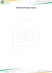
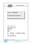
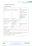
1
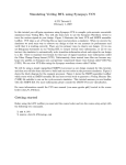
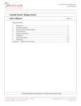
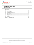
FBDA8281-50
Cascade 4300 HMI Specification
Cascade 4300 4.3” Panel Mount HMI Specification
Model: FBDA8281-50
Table of Contents
1. General Specifications ................................................................................... 2
2. Electrical Specifications and Configuration .................................................... 2
3. External Connectors ...................................................................................... 2
3.1. RS-485 .................................................................................................... 2
3.2. Ethernet................................................................................................... 3
3.3. USB 1.1 Host........................................................................................... 3
3.4. USB 2.0 Device ....................................................................................... 3
4. Internal Connectors........................................................................................ 4
4.1. Connector Layout .................................................................................... 4
4.2. JTAG (J2) ................................................................................................ 5
4.3. System Bus (J7 and J8) .......................................................................... 5
4.4. General Purpose I/O (J10) ...................................................................... 8
4.5. UART, SPI, I2C, and INT (J1) .................................................................. 9
4.6. Ethernet, RS-232, and RS-485 (J3) ...................................................... 10
4.7. Microphone (J97) .................................................................................. 10
4.8. Speaker (J98)........................................................................................ 10
5. Replacing the Operating System Image ...................................................... 11
6. Quality Assurance........................................................................................ 12
7. Mechanical Drawing..................................................................................... 13
7.1. Enclosure .............................................................................................. 13
7.2. Main PCB Outline .................................................................................. 14
7.3. Power Board PCB Outline ..................................................................... 14
Date
4/30/2009
6/1/2009
Page
Rev: 1
Rev: 2
6/23/2009
6/25/2009
1/13/2009
5/12/2010
Rev: 3
Rev: 4
Rev: 5
Rev: 6
Summary
Preliminary Release
Removed separate RS-232 connector
Added part numbers for speaker and mic
Added PCB drawings
Updated OS Image download procedure.
Corrected mating part numbers for J1 and J3.
Clarified pin functions for J3
Updated address
Prepared By: Tony Gray
Approved By: Marty Wakita
12700 Park Central, Suite 750, Dallas, TX 75251
Tel: 972-437-3888
Fax: 972-437- 2562
[email protected]
www.OcularLcd.com
Page 1 of 15
FBDA8281-50
Cascade 4300 HMI Specification
1. General Specifications
Parameter
Screen Size
Display Format
Active Area
Pixel Size
Colors
Brightness
Touch Screen
Outline Dimensions
Weight
Viewing Angle
Speaker
Processor
Speed
Flash Memory
Operating System
Operating Temperature
Storage Temperature
Table 1
Specification
4.3 (Diagonal)
480 RGB x 272
95.04 (W) x 53.856 (H)
198 (W) x 198 (H)
16,777,216 (24-bit)
350 (Maximum)
4-Wire Resistive
148 (W) x 99 (H) x 35 (D)
400 (complete unit)
6 o’clock
2
ARM920T
533
64
Win CE 5.0
0 to 50
-40 to 85
Unit
inch
pixels
mm
μm
colors
cd/m2
─
mm
g
─
watts
─
MHz
MB
─
°C
°C
2. Electrical Specifications and Configuration
Parameter
Power Voltage
Power Current
Table 2
Symbol
Min.
VCC
11.4
ICC
─
Max.
12.6
1
Unit
V
A
Remark
Note 1
Note 2
Note 1: Power plug is 5.5mm outer diameter, 2.10mm inner diameter, center positive.
Note 2: Maximum current includes 0.5A for USB host port.
3. External Connectors
3.1.
RS-485
Tied to UART2 on the processor.
Port is half-duplex.
Connector is standard RJ-11 (phone jack).
12700 Park Central, Suite 750, Dallas, TX 75251
Tel: 972-437-3888
Fax: 972-437- 2562
[email protected]
www.OcularLcd.com
Page 2 of 15
FBDA8281-50
Cascade 4300 HMI Specification
Table 3
Pin No. Symbol
Description
1
Shield Cable shield
2
A
RS-485 A Signal
3
GND
4
GND
5
B
RS-485 B Signal
6
GND
Remarks
Optional
Note 1
Note 1
Note 1: The Request To Send (RTS) line is used for flow control. When RTS is
high the unit is transmitting; when RTS is low the unit is receiving.
3.2.
Ethernet
Connector is standard RJ-45.
Pinout follows standard Ethernet pinout.
Ethernet port is 10/100.
Power over Ethernet (POE) is not supported.
3.3.
USB 1.1 Host
Connector is standard USB Type A.
Pinout follows standard USB Type A pinout.
USB is host at full speed (12 Mbps).
3.4.
USB 2.0 Device
Connector is mini-USB Type B.
Pinout follows standard USB Type B pinout.
USB device supports both full speed (12 Mbps) and high speed (480
Mbps).
12700 Park Central, Suite 750, Dallas, TX 75251
Tel: 972-437-3888
Fax: 972-437- 2562
[email protected]
www.OcularLcd.com
Page 3 of 15
FBDA8281-50
Cascade 4300 HMI Specification
4. Internal Connectors
Connector Layout
J1
4.1.
Table 4
Connector
Designation
J2
J7 and J8
J10
J1
J3
J97
J98
12700 Park Central, Suite 750, Dallas, TX 75251
Tel: 972-437-3888
Fax: 972-437- 2562
Description
JTAG
System Bus
General Purpose I/O
UART, SPI, I2C, and INT
Ethernet, UART, and RS-485
Microphone
Speaker
[email protected]
www.OcularLcd.com
Page 4 of 15
FBDA8281-50
Cascade 4300 HMI Specification
4.2.
4.3.
JTAG (J2)
Connector part number is equivalent to Molex 015-91-0200.
Mating connector is Molex 022-55-2201 or equivalent.
Table 5
Pin No. Symbol
Description
Remarks
1
3.3V
Power
2
3.3V
Power
3
nTRST TAP Reset
Connected to nTRST on processor
4
GND
Ground
5
TDI
TAP Data Input
Connected to TDI on processor
6
GND
Ground
7
TMS
TAP Mode Select
Connected to TMS on processor
8
GND
Ground
9
TCK
TAP Clock
Connected to TCK on processor
10
GND
Ground
11
N/C
No connect
12
GND
Ground
13
TDO
TAP Data Output
Connected to TDO on processor
14
GND
Ground
15
RESET Reset
Drive low to reset entire system
16
GND
Ground
17
N/C
No connect
18
GND
Ground
19
N/C
No connect
20
GND
Ground
System Bus (J7 and J8)
J7 connector part number is equivalent to Samtec FLE-125-01-G-DV-A.
Mating cable is Samtec FFMD-25-S-02.00-01 or equivalent.
Table 6
Pin No. Symbol
Description
Remarks
1
GND
Ground
2
GND
Ground
3
RDATA1 Data Bus 1
4
RDATA0 Data Bus 0
5
RDATA3 Data Bus 3
6
RDATA2 Data Bus 2
7
RDATA5 Data Bus 5
8
RDATA4 Data Bus 4
9
RDATA7 Data Bus 7
10
RDATA6 Data Bus 6
11
RDATA9 Data Bus 9
12
RDATA8 Data Bus 8
13
RDATA11 Data Bus 11
14
RDATA10 Data Bus 10
15
RDATA13 Data Bus 13
12700 Park Central, Suite 750, Dallas, TX 75251
Tel: 972-437-3888
Fax: 972-437- 2562
[email protected]
www.OcularLcd.com
Page 5 of 15
FBDA8281-50
Cascade 4300 HMI Specification
16
17
18
19
20
21
22
23
24
RDATA12
RDATA15
RDATA14
3.3V
3.3V
RADDR16
RADDR17
RADDR18
RADDR23
Data Bus 12
Data Bus 15
Data Bus 14
Power
Power
Address Bus 16
Address Bus 17
Address Bus 18
Address Bus 23
25
nRCS2
Memory Chip Select 2
26
nRCS3
27
nRCS4
28
nRCS5
29
30
nRBEO
nRBE1
31
nRWE
32
nROE
33
34
35
36
37
38
39
40
41
42
43
44
45
46
47
48
49
50
RADDR1
RADDR0
RADDR3
RADDR2
RADDR5
RADDR4
RADDR7
RADDR6
RADDR9
RADDR8
RADDR11
RADDR10
RADDR13
RADDR12
RADDR15
RADDR14
GND
GND
SROM Address 0x1000:0000 to
0x1040:0000
SROM Address 0x1800:0000 to
Memory Chip Select 3
0x1840:0000
SROM Address 0x2000:0000 to
Memory Chip Select 4
0x2040:0000
SROM Address 0x2800:0000 to
Memory Chip Select 5
0x2840:0000
Byte selection
Upper/lower byte selection; used
with 16-bit SRAM
Byte selection
L = Write cycle is active, H =
Write Active
Write cycle is not active
L = Read cycle is active, H = Read
Read Active
cycle is not active
Address Bus 1
Address Bus 0
Address Bus 3
Address Bus 2
Address Bus 5
Address Bus 4
Address Bus 7
Address Bus 6
Address Bus 9
Address Bus 8
Address Bus 11
Address Bus 10
Address Bus 13
Address Bus 12
Address Bus 15
Address Bus 14
Ground
Ground
12700 Park Central, Suite 750, Dallas, TX 75251
Tel: 972-437-3888
Fax: 972-437- 2562
100 mA
100 mA
[email protected]
www.OcularLcd.com
Page 6 of 15
FBDA8281-50
Cascade 4300 HMI Specification
J8 connector part number is equivalent to Samtec FLE-106-01-G-DV-A.
Mating cable is Samtec FFMD-06-S-02.00-01 or equivalent.
Table 7
Pin No. Symbol
Description
Remarks
nWAIT
Bus Wait Request
L = Suspend bus cycle, H = continue; tied
1
to nWAIT input on processor; pulled high
GPIO Port G Bit 3 (also
Tied to EINT11/GPG3 on processor
2
EINT11/GPG3
External Interrupt 11)
3
RESET
Reset
Drive low to reset entire system
GPIO Port G Bit 9 (also
Tied to EINT17/GPG9 on processor
4
EINT17/GPG9
External Interrupt 17)
5
GPG14
GPIO Port G Bit 14
Refer to chapter 5 of the Samsung 2443
6
RSMAVD
SRAM Bus Address Valid
User Manual
L = Read cycle is active, H = Read cycle is
7
nROE
Read Active
not active
Refer to chapter 5 of the Samsung 2443
8
RSMCLK
SRAM Bus Clock
User Manual
9
GPB7
GPIO Port B Bit 7
Refer to chapter 5 of the Samsung 2443
10
RSMBWAIT
SRAM Bus Burst Wait
User Manual
GPIO Port G Bit 5 (also
Tied to EINT13/GPG5 on processor
11
EINT13/GPG5
External Interrupt 13)
12
GND
Ground
12700 Park Central, Suite 750, Dallas, TX 75251
Tel: 972-437-3888
Fax: 972-437- 2562
[email protected]
www.OcularLcd.com
Page 7 of 15
FBDA8281-50
Cascade 4300 HMI Specification
4.4.
General Purpose I/O (J10)
Connector part number is equivalent to Samtec FLE-111-01-G-DV-A.
Mating cable is Samtec FFMD-11-S-02.00-01 or equivalent.
Table 8
Pin No.
Symbol
Description
Remarks
1
GND
Ground
2
GND
Ground
3
GPJ0
GPIO Port J Bit 0
4
nSS1
SPI Active
5
GPJ1
GPIO Port J Bit 1
GPIO Port L Bit 12 (also
Tied to SPIMISO1/GPL12 on processor
6
MISO1/GPL12
SPI Master Input)
7
GPJ2
GPIO Port J Bit 2
GPIO Port L Bit 11 (also
Tied to SPIMOSI1/GPL11 on processor
8
MOSI1/GPL11
SPI Master Output)
9
GPJ3
GPIO Port J Bit 3
GPIO Port L Bit 10 (also
Tied to SPICLK1/GPL10 on processor
10
SCLK1/GPL10
SPI Clock)
11
GPJ4
GPIO Port J Bit 4
12
AIN0
Analog Input 0
Tied to AIN0 on processor
13
GPJ5
GPIO Port J Bit 5
14
AIN1
Analog Input 1
Tied to AIN1 on processor
15
GPJ6
GPIO Port J Bit 6
16
GPJ9
GPIO Port J Bit 9
17
GPJ7
GPIO Port J Bit 7
18
3.3V
Power Supply
100 mA
19
GPJ8
GPIO Port J Bit 8
20
3.3V
Power Supply
100 mA
21
GND
Ground
22
GND
Ground
12700 Park Central, Suite 750, Dallas, TX 75251
Tel: 972-437-3888
Fax: 972-437- 2562
[email protected]
www.OcularLcd.com
Page 8 of 15
FBDA8281-50
Cascade 4300 HMI Specification
4.5.
UART, SPI, I2C, and INT (J1)
Connector part number is equivalent to Molex 87758-2016.
Mating connector is Molex 79107-7009 or equivalent.
Table 9
Pin No.
Symbol
Description
Remarks
1
N/C
No Connect
2
N/C
No Connect
3
IICSCL
I2C Clock
4
N/C
No Connect
5
IICSDA
I2C Data
GPIO Port F Bit 0 (also Tied to EINT0/GPF0 on processor
6
EINT0/GPF0
External Interrupt 0)
7
N/C
No Connect
8
N/C
No Connect
9
N/C
No Connect
GPIO Port E Bit 12
Tied to SPIMOSI0/GPE12 on processor
10
MOSI0/GPE12 (also SPI Master
Output)
11
N/C
No Connect
GPIO Port E Bit 13
Tied to SPICLK0/GPE13 on processor
12
SCLK0/GPE13
(also SPI Clock)
13
GND
Ground
GPIO Port E Bit 11
Tied to SPIMISO0/GPE11 on processor
14 MISO0/GPE112 (also SPI Master
Input)
15
RSTOUT
Reset Output
Driven low when the processor resets
GPIO Port H Bit 0
Tied to TXD0/GPH0 on processor
16
TXD0/GPH0
(also UART Tx)
17
3.3V
Power
100 mA
GPIO Port H Bit 1
Tied to RXD0/GPH1 on processor
18
RXD0/GPH1
(also UART Rx)
19
N/C
No Connect
20
N/C
No Connect
12700 Park Central, Suite 750, Dallas, TX 75251
Tel: 972-437-3888
Fax: 972-437- 2562
[email protected]
www.OcularLcd.com
Page 9 of 15
FBDA8281-50
Cascade 4300 HMI Specification
4.6.
Ethernet, RS-232, and RS-485 (J3)
4.7.
Microphone (J97)
4.8.
Speaker (J98)
Connector part number is equivalent to Molex 87759-2014.
Mating connector is Molex 79107-7010 or equivalent.
Table 10
Pin No.
Symbol
Description
Remarks
1
GND
Ground
2
GND
Ground
3
3.3V
3.3V Power Output
100 mA
4
3.3V
3.3V Power Output
100 mA
5
RXIEthernet RXI6
RXI+
Ethernet RXI+
7
TXO+
Ethernet TXO+
8
TXOEthernet TXI+
9
SPEED
Ethernet Speed
L = 100 Mbps, Float = 10 Mbps
10
LED Link
Ethernet Link Light
11
GND
Ground
12
GND
Ground
13
RS485 B
RS485 B
RS-485 is driven by TXD2 and RXD2
on processor
14
RS485 A
RS485 A
15
GND
Ground
16
GND
Ground
17
12V
12V Power Input
250 mA
18
12V
12V Power Input
250 mA
19
12V
12V Power Input
250 mA
20
12V
12V Power Input
250 mA
21
RS232 Rx RS232 Rx
RS-232 is driven by TXD1 and RXD1
on processor
22
RS232 Tx RS232 Tx
Connector part number is equivalent to Molex 53047-0210.
Mating connector is Molex 51021-0200 or equivalent.
Table 12
Pin No. Symbol
Description
1
MIC
Microphone Input
2
GND
Ground
Connector part number is equivalent to Molex 53047-0210.
Mating connector is Molex 51021-0200.
Table 13
Pin No. Symbol
Description
1
SPK1
Speaker Output 1
2
SPK2
Speaker Output 2
Note: Mating speaker must be 8Ω
12700 Park Central, Suite 750, Dallas, TX 75251
Tel: 972-437-3888
Fax: 972-437- 2562
[email protected]
www.OcularLcd.com
Page 10 of 15
FBDA8281-50
Cascade 4300 HMI Specification
5. Replacing the Operating System Image
You can replace the Windows CE image with your own image. Once you
have built your NK.bin file, follow these steps to load it into the Cascade
4300.
You will need to an RS-232 serial cable between your PC and the Cascade
4300. The RS-232 port is available on an internal connector on the Cascade
4300 PCB. You will also need a USB cable, but it should not be attached at
the beginning of the procedure. The USB device port is located just below
the SD card slot. The connector type is mini-USB Type B.
Once the RS-232 cable is in place, insert the Cascade 4300 CD in your PC
and follow these steps:
1) Make sure that the Cascade 4300 is turned off.
2) On the CD run \Image Downloader\DNW.exe.
3) Go to the Configuration->Options menu. Set the COM port. Set the baud
rate to 115200.
Note: DNW only supports COM1 through COM4. If you are using a higher COM port,
you can use any terminal program for the serial communications part of this
procedure.
Note: If you want DNW to save your options as the default settings, copy the entire
Image Downloader folder to your hard drive and run DNW from there.
4) Set the USB Port Download Address to 0x30200000 (this should be the
default) and select OK.
5) Select Serial Port->Connect.
6) Turn on the Cascade 4300.
7) The boot loader shows a 5 second countdown in the serial window.
Press the space bar during these 5 seconds to enter the EBOOT menu.
8) Connect the USB cable. The title bar of DNW should show [USB:OK].
Note: The first time you attach the USB cable you will be prompted to install the USB
driver. Navigate to the Cascade 4300 CD and select the Image Downloader folder.
When prompted, choose the first entry in the list. When prompted for a CD, navigate
again to the Image Downloader folder.
9) Press 5 to set the startup image to LAUNCH EXISTING.
10) Press 6 to set the Program disk image into SmartMedia card to Enabled.
11) Press F to perform a low level format of the Flash.
12) Press U to start downloading the new NK.bin file.
13) Select USB Port->UBOOT (WINCE500)->UBOOT.
12700 Park Central, Suite 750, Dallas, TX 75251
Tel: 972-437-3888
Fax: 972-437- 2562
[email protected]
www.OcularLcd.com
Page 11 of 15
FBDA8281-50
Cascade 4300 HMI Specification
14) Select your new NK.bin file.
Note: The NK.bin file that shipped with your unit is located on the Cascade 4300 CD
at \OS Image\Default NK.bin.
15) During the download you may see messages stating that some sectors
are not writeable. This is normal.
16) When the download is finished, Done will be displayed.
17) Cycle power to the Cascade 4300 to begin running with the new OS
image.
6. Quality Assurance
Table 14
No.
Test items
Test condition
1
High Temperature Operation Test Ta=60°C Dry 24h
2
Low Temperature Operation Test Cold start @ -20°C
Operational @ 0°C for 24h
3
High Temperature and High
Operational @ 60°C 90%RH for
Humidity Operation Test
240h
±8KV (Contact)
4
Electro Static Discharge Test
±15KV (Air)
Sine wave, 10Hz to 50Hz
5
Vibration Test (non-operating)
1.5mm amplitude
3 axis, 2 hours/axis
12700 Park Central, Suite 750, Dallas, TX 75251
Tel: 972-437-3888
Fax: 972-437- 2562
[email protected]
www.OcularLcd.com
Page 12 of 15
FBDA8281-50
Cascade 4300 HMI Specification
7. Mechanical Drawing
7.1.
Enclosure
12700 Park Central, Suite 750, Dallas, TX 75251
Tel: 972-437-3888
Fax: 972-437- 2562
[email protected]
www.OcularLcd.com
Page 13 of 15
FBDA8281-50
Cascade 4300 HMI Specification
7.2.
Main PCB Outline
7.3.
Power Board PCB Outline
12700 Park Central, Suite 750, Dallas, TX 75251
Tel: 972-437-3888
Fax: 972-437- 2562
[email protected]
www.OcularLcd.com
Page 14 of 15
FBDA8281-50
Cascade 4300 HMI Specification
12700 Park Central, Suite 750, Dallas, TX 75251
Tel: 972-437-3888
Fax: 972-437- 2562
[email protected]
www.OcularLcd.com
Page 15 of 15