1
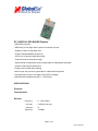
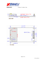
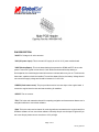
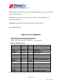
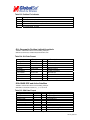
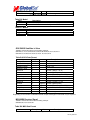
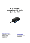
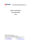
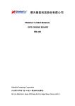
ET-102/ER-102
GPS RECEIVER ENGINE BOARD
PRODUCT GUIDE
Globalsat Technology Corporation (Taiwan)
www.globalsat.com.tw
USGlobalSat, Inc. (USA)
www.usglobalsat.com
Page 1 of 10
ET-102_data.doc
ET-102/ER-102 GPS BOARD Features
*SiRf GPS Architecture
*SiRF StarII (X-Trac) High and low power consumption chip set
* SnapLock 100ms re-acquisition time
* Support standard NMEA 0183 protocol
* All-in-view 12-channel parallel processing
* Cold start under 45 seconds, average
* Optional build-in SuperCap to reserve system data for rapid satellite acquisition
* Superior urban canyon performance
*Foliage Lock for Weak signal tracking
*Built-in super cap to reserve system data for rapid satellite acquisition
*Full-duplex RS-232 port for navigation and control messages.
*Differential GPS capability through 2nd RS-232 port
SPECIFICATIONS
Electrical
Characteristics
Receiver
Frequency
L1, 1575.42 MHz
C/A code
1.023 MHz chip rate
Channels
12
Sensitivity
-170dBW
Page 2 of 10
ET-102_data.doc
Accuracy
Position
15 meters, 2D RMS, SA off
10 meters, 2d RMS, WAAS enable(SA off)
Velocity
Time
0.1 m/s 95% (SA off)
1 microsecond synchronized to GPS time
Datum
Default
WGS-84
Acquisition Time
Reacquisition
Hot start
0.1 sec., average
8 sec., average
Warm start
38 sec., average
Cold start
48 sec., average
Dynamic Conditions
Altitude
18,000 meters (60,000 feet) max
Velocity
515 meters /second (1000 knots) max
Power
Main power input
Current supply
3.3 Vdc ~ 5.5Vdc
60mA typical
25mA on trickle power mode
Backup power
Backup current
+2.5V to +3.6V
10uA typical
Serial Port
Ports
Electrical level
One for GPS, one for DGPS
TTL level (ET-102), Output voltage level: 0~3.5V
RS-232 level (ER-102)
Communication
Code type
GPS Protocol
GPS Output Message
Full duplex asynchronous
ASCII
SiRf binary.NMEA 0183 changeable(Default:NMEA)
SiRf binary>> Position, Velocity, Altitude, Status and control
NMEA 0183>> GGA,GSA,GSV,RMC(VTG and GLL are
optional
Page 3 of 10
ET-102_data.doc
GPS Transfer Rate
DGPS Protocol
Software Command setting (Default:4800bps for NMEA)
RTCM SC-104,ver2.00, type 1,2 and 9
Time Mark
Level
Pulse Duration
Time Reference
Measurement
Active Antenna
TTL
100ms
At the pulse positive edge
Aligned to GPS sec., +/- 1us
--MCX, SMA, SMB, or others OEM specified connector avalible
Connector
Environmental
Characteristics
Temperature
Operating
-40 deg. C to +80 deg. C
Storage
-40 deg. C to +85 deg. C
Humidity
Up to 95% non-condensing
All product specifications subject to change without notice.
PIN ASSIGNMENT
Pin No.
Name
Description
1
VANT
2
VDC
3.8V~6.5V DC Power Input
Input
3
VBAT
Backup Battery
Input
4
VDC
(Shorted with pin 2)
Input
5
PBRES
Push Button Reset Input (Active Low)
Input
6
RESERVED
(Reserved)
7
SELECT
Down-load data from RS232 to flash ROM
(Reserved)
8
RESERVED
(Reserved)
Antenna DC Voltage
Type
Input
Page 4 of 10
ET-102_data.doc
9
RESERVED
(Reserved)
10
GND
Ground
11
TXA
Serial Data Output A (GPS Data)
Output
12
RXA
Serial Data Input A (Command)
Input
13
GND
Ground
14
TXB
Serial Data Output B (No Used)
Output
15
RXB
Serial Data Input B (DGPS Data)
Input
16
GND
Ground
17
RESERVED
(Reserved)
18
GND
Ground
19
TIMEMARK
1PPS Time Mark Output
20
RESERVED
(Reserved)
Output
Page 5 of 10
ET-102_data.doc
DIMENSIONS
21.5mm x 71.12mm x 7mm
Page 6 of 10
ET-102_data.doc
CONNECTOR INTERFACE
PIN DESCRIPTION
*VANT: DC Voltage is for active antenna.
*VDC (DC power input): This is the main DC supply for a 3.8V~6.5V power module board
*VBAT (Backup Batter): This is the batter backup that powers the SRAM and RTC when main
power is removed. Typical current draw is 10uA. Without and external backup battery or
Gold-capacitor, the module/engine board will execute a cold start after every turn on. To achieve the
faster start- capacitor should be installed. To maximize battery lifetime, the battery Voltage should
not exceed the supply voltage and should be between 2.5v and 3.6V.
*PBRES (Push-button reset): This pin provides an active-low reset input to the engine board. It
causes the engine board to reset and start searching for satellites
*SELECT: Do not connect
*TXA: This is the main transmits channel for outputting navigation and measurement data to user’s
navigation software or user written software.
*RXA: This is the main receive channel for receiving software commands to the engine board from
SiRfdemo software or from user written software. Normally this pin must be kept in High and if you
don’t use this pin please connect a resistor to 3.5V pull high
Page 7 of 11
ET-102_data.doc
*TXB: No function as so far (Do not connect)
*RXB: This is the auxiliary receive channel for inputting differential corrections to the engine board
to enable DGPS navigation.
*Time Mark: This pin provides one pulse-per-second output from the engine board that is
synchronized to GPS time.
*GND: GND provides the ground for the engine boards. Connect all grounds
*Others: Do not connect.
NMEA OUTPUT COMMANDS
GGA-Global Positioning System Fixed Data
Table B-2 contains the values for the following example:
$GPGGA, 161229.487,3723.2475,N, 12158.3416,W, 1,07,1.0,9.0,M, 0000*18
Table B-2 GGA Data Format
Name
Example
Units
Description
Message ID
$GPGGA
GGA protocol header
UTC Time
161229.487
hhmmss.sss
Latitude
3723.2475
ddmm.mmmm
N/S Indicator
N
N=north or S=south
Longitude
12158.3416
dddmm.mmmm
E/W Indicator
W
E=east or W=west
Position Fix
1
See Table B-3
Satellites Used
07
Range 0 to 12
HDOP
1.0
Horizontal Dilution of Precision
1
MSL Altitude
9.0
meters
Units
M
meters
Geoid Separation1
meters
Units
M
meters
Age of Diff. Corr.
second Null fields when DGPS is not used
Diff. Ref. Station ID 0000
Checksum
*18
<CR><LF>
End of message termination
SiRF Technology Inc. does not support geoid corrections. Values are WGS84 ellipsoid heights.
Page 8 of 11
ET-102_data.doc
Table B-3 Position Fix Indicator
Value
0
1
2
3
Description
Fix not available or invalid
GPS SPS Mode, fix valid
Differential GPS, SPS Mode , fix valid
GPS PPS Mode, fix valid
GLL-Geographic Position-Latitude/Longitude
Table B-4 contains the values for the following example:
$GPGLL,3723.2475,N,12158.3416,W,161229.487,A*2C
Table B-4 GLL Data Format
Name
Message ID
Latitude
N/S Indicator
Longitude
E/W Indicator
UTC Position
Status
Checksum
<CR><LF>
Example
$GPGLL
3723.2475
n
12158.3416
W
161229.487
A
*2C
Units
Description
GLL protocol header
ddmm.mmmm
N=north or S=south
dddmm.mmmm
E=east or W=west
hhmmss.sss
A=data valid or V=data not valid
End of message termination
GSA-GNSS DOP and Active Satellites
Table B-5 contains the values for the following example:
$GPGSA,A,3,07,02,26,27,09,04,15,,,,,,1.8,1.0,1.5*33
Table B-5 GSA Data Format
Name
Message ID
Mode1
Mode2
Satellite Used1
Satellite Used1
…..
Satellite Used1
PDOP
HDOP
VDOP
Example
$GPGSA
A
3
07
02
1.8
1.0
1.5
Units
Description
GSA protocol header
See Table B-6
See Table B-7
Sv on Channel 1
Sv on Channel 2
Sv on Channel 12
Position dilution of Precision
Horizontal dilution of Precision
Vertical dilution of Precision
Page 9 of 12
ET-102_data.doc
Checksum
<CR><LF>
*33
End of message termination
(1. Satellite used in solution)
Table B-6 Mode1
Value
M
A
Description
Manual-forced to operate in 2D or 3D mode
2Dautomatic-allowed to automatically switch 2D/3D
Table B-7 Mode 2
Value
1
2
3
Description
Fix Not Available
2D
3D
GSV-GNSS Satellites in View
Table B-8 contains the values for the following example:
$GPGSV,2,1,07,07,79,048,42,02,51,062,43,26,36,256,42,27,27,138,42*71
$GPGSV,2,2,07,09,23,313,42,04,19,159,41,15,12,041,42*41
Table B-8 GSV Data Format
Description
Name
Example
Message ID
$GPGSV
GSV protocol header
1
Number of Messages 2
Range 1 to 3
1
Message Number
1
Range 1 to 3
Satellites in View
07
Satellite ID
07
Channel 1(Range 1 to 32)
Elevation
79
degrees Channel 1(Maximum90)
Azimuth
048
degrees Channel 1(True, Range 0 to 359)
SNR(C/No)
42
dBHz
Range 0 to 99,null when not tracking
…….
…….
Satellite ID
27
Channel 4 (Range 1 to 32)
Elevation
27
Degrees Channel 4(Maximum90)
Azimuth
138
Degrees Channel 4(True, Range 0 to 359)
SNR(C/No)
42
dBHz
Range 0 to 99,null when not tracking
Checksum
*71
<CR><LF>
End of message termination
Depending on the number of satellites tracked multiple messages of GSV data may be required.
MSS-MSK Receiver Signal
Table B-9 contains the values for the following example:
$GPMSS,55,27,318.0,100,*66
Table B-9 MSS Data Format
Name
Example
Units
Description
Page 10 of 13
ET-102_data.doc
Message ID
Signal Strength
Signal-to-Noise Ratio
Beacon Frequency
Beacon Bit Rate
$GMSS
55
27
318.0
100
MSS protocol header
SS of tracked frequency
SNR of tracked frequency
Currently tracked frequency
Bits per second
dB
dB
kHz
The MSS NMEA message can only be polled or scheduled using the MSK MNEA input message.
Reference “MSK-MSK Receiver Interface” (Note: Available upon request, not included in this document).
RMC-Recommended Minimum Specific GNSS Data
Table B-10 contains the values for the following example:
$GPRMC,161229.487,A,3723.2475,N,12158.3416,W,0.13,309.62,120598,,*10
Table B-10 RMC Data Format
Name
Message ID
UTC Time
Status
Latitude
N/S Indicator
Longitude
E/W Indicator
Speed Over Ground
Course Over Ground
Date
Magnetic Variation2
Checksum
<CR><LF>
Example
$GPRMC
161229.487
A
3723.2475
N
12158.3416
W
0.13
309.62
120598
Units
knots
degrees
degrees
Description
RMC protocol header
hhmmss.sss
A=data valid or V=data not valid
ddmm.mmmm
N=north or S=south
dddmm.mmmm
E=east or W=west
True
ddmmyy
E=east or W=west
*10
End of message termination
SiRF Technology Inc. does not support magnetic declination. All “course over ground” data are geodetic
WGS48 directions.
VTG-Course Over Ground and Ground Speed
Table B-10 contains the values for the following example:
$GPVTG,309.62,T,,M,0.13,N,0.2,K*6E
Table B-11 RMC Data Format
Name
Message ID
Example
$GPVTG
Units
Description
VTG protocol header
Page 11 of 13
ET-102_data.doc
Course
Reference
Course
Reference
Speed
Units
Speed
Units
Checksum
<CR><LF>
309.62
T
degrees
degrees
M
0.13
N
0.2
K
*6E
knots
Km/hr
Measured heading
True
Measured heading
Magnetic
Measured horizontal speed
Knots
Measured horizontal speed
Kilometers per hour
End of message termination
All specifications subject to change without notice.
Page 12 of 13
ET-102_data.doc