1
D396-14-880
Issue H
Instruction Manual
EXC Turbomolecular Pump Controllers
Description
Item Number
EXC120 Controller
EXC120E Controller
EXC300 Controller
EXC300M Controller
D396-16-000
D396-17-000
D396-14-000
D396-15-000
Manor Royal, Crawley, West Sussex, RH10 2LW, UK
Telephone: +44 (0) 1293 528844 Fax: +44 (0) 1293 533453
http://www.bocedwards.com
We,
BOC Edwards,
Manor Royal,
Crawley,
West Sussex RHlO2LW,UK
declare under our sole responsibility that the product(s)
Turbomolecular Pump Controllers
EXC300
EXC300M
EXC120
EXCl20E
D396-14-000
D396-15-000
D396-16-000
D396-17-000
to which this declaration r,elatesis in conformity with the following standard(s)
or other normative document(s)
IEC1010-1 (1992)
EN61326
(Class B Emissions)
following
Safety Requirements for Electrical Equipment for Measurement,
Control and Laboratory Use.
Electrical Equipment for Measurement, Control and Laboratory Use
-EMC Requirements.
the provisions O1:
73/023/
89/336/
Low Voltage Directive.
Electromagnetic Compatibility Directive
EEC
EEC
0
'i'
~
~
-JD~~
Dr. J.D.
Watson,
Senior
4{f.t(ol
~-Technical
Manager,
VED
Date
and
5H0'"'\~v-.
Place
~
"'
;!4
~
~
CONTENTS
IPSITECH 8039-02
Section
Title
Page
1
1.1
1.2
1.3
1.4
1.5
1.6
1.7
1.7.1
1.7.2
1.7.3
1.7.4
1.7.5
1.8
1.8.1
1.8.2
1.8.3
1.9
1.9.1
1.9.2
1.9.3
1.10
INTRODUCTION
Scope and definitions
Description
Controls and indicators (EXC120/300/300M only)
Bakeout band control (EXC120/300/300M only)
Connection of an Active gauge
Backing pump control (EXC120/300/300M only)
Logic interface
Introduction
Electrical supplies
Control inputs
Status outputs
Analogue outputs
Vent-valve control
Introduction
Vent on Stop
Vent on Fail and Vent on Axial Emergency
Controller Fail conditions
General
Internal Timer
Axial Emergency (EXC300M only)
Electrical connections
1
1
2
3
6
7
7
7
7
8
8
10
10
10
10
11
11
12
12
12
13
13
2
2.1
2.2
2.3
2.4
2.5
2.6
2.7
TECHNICAL DATA
General
Operating and storage data
Mechanical data
Logic interface
Factory settings
Electrical connectors
Fuse ratings
17
17
17
17
17
21
21
21
3
3.1
3.2
3.3
3.4
3.5
3.6
3.7
3.8
3.9
3.10
3.11
INSTALLATION
Unpack and inspect
Fit the Controller
Introduction to Controller electrical connections
Connect the electrical supply
Connect additional earth (ground) bonding (if required)
Connect the EXT pump
Connect the backing pump (EXC120/300/300M only)
Connect the bakeout band (EXC120/300/300M only)
Connect an Active gauge
Connect the logic interface to your equipment
Adjust the Normal speed setpoint
22
22
23
23
27
27
28
28
29
30
30
31
EXC Turbomolecular Pump Controllers
i
Section
3.12
3.13
3.13.1
3.13.2
3.13.3
Title
Page
Adjust the Internal Timer
Configure the Controller
Introduction
Enable/disable the Internal Timer to monitor low pump speed
Vent options
32
32
32
32
33
4
4.1
4.2
4.3
4.4
4.5
4.6
4.7
4.8
4.9
4.10
OPERATION
Start-up
Standby
Bakeout band control (EXC120/300/300M only)
Operation with high inlet pressure
Operation with high pump temperature
The hours counter (EXC300 only)
Normal shutdown
Automatic shutdown after Fail condition
Reset the Controller after Fail condition
Electrical supply failure
34
34
34
35
35
35
36
36
37
37
37
5
5.1
5.2
5.2.1
5.2.2
5.3.3
38
5.4
5.5
MAINTENANCE
Safety
Replace a fuse
Introduction
Replace the electrical supply fuse
Replace the bakeout band fuse (EXC120/300/300M only)
Fault finding
Clean the Controller
38
38
38
38
38
6
6.1
6.2
STORAGE AND DISPOSAL
Storage
Disposal
39
39
39
7
7.1
7.2
7.3
7.3.1
7.3.2
7.3.3
7.3.4
7.3.5
SPARES AND ACCESSORIES
Introduction
Spares
Accessories
Pump-to-controller cable
BX bakeout band (EXC120/300/300M only)
TAV vent-valve
ACX air-cooler
Active vacuum gauges
40
40
40
40
40
41
41
41
42
8
ENGINEERING DIAGRAMS
43
39
39
RETURN OF BOC EDWARDS EQUIPMENT
ii
EXC Turbomolecular Pump Controllers
Illustrations
Figure
Title
Page
1
2
3
4
5
6
7
8
9
10
11
12
13
14
15
16
EXC120 Controller front panel
EXC300/300M Controller front panel (EXC300M shown)
Rear panel of the EXC120 Controller
Rear panel of the EXC120E Controller
Rear panel of the EXC300/300M Controller
EXC120/300/300M Controller dimensions (mm)
EXC120E Controller dimensions (mm)
Schematic diagram of EXC120 & EXC120E Controller electrical connections
Schematic diagram of EXC300 & EXC300M Controller electrical connections
Direct operation of the backing pump
Operation of the backing pump through a contactor
Top cover of the Controller
Hours counter (EXC300 only)
EXC120/120E/300 Controller to EXT pump connections
EXC300M Controller to EXT pump connections
Active Gauge connector
4
5
14
15
16
19
20
25
26
29
29
31
36
43
44
45
Tables
Table
1
2
3
4
5
Title
Technical data
Checklist of contents
Logic interface pins
Selection of vent-valve control options
Active Gauge connector pins
Page
18
22
24
33
45
Associated Publications
Publication title
EXT Pump Accessories
EXT70 and EXT250 Turbomolecular pumps
EXT351 and EXT501 Turbomolecular Pumps
EXT250M Turbomolecular Pump
EXC Turbomolecular Pump Controllers
Publication Number
B580-66-880
B722-01-880
B727-20-880
B735-01-880
iii
(This page deliberately left blank)
iv
EXC Turbomolecular Pump Controllers
1
INTRODUCTION
1.1
Scope and definitions
This manual provides installation, operation and maintenance instructions for the BOC
Edwards EXC120, EXC120E, EXC300 and EXC300M Turbomolecular Pump Controllers. You
must use the Controller as specified in this manual.
Read this manual before you install and operate the Controller. Important safety information is
highlighted as WARNING and CAUTION instructions; you must obey these instructions. The
use of WARNINGS and CAUTIONS is defined below.
WARNING
Warnings are given where failure to observe the instruction could result in injury or death
to people.
CAUTION
Cautions are given where failure to observe the instruction could result in damage to the
equipment, associated equipment or process.
The units used throughout this manual conform to the SI international system of units of
measurement.
In accordance with the recommendations of IEC1010, the following warning symbols appear on
the Controller.
Caution - refer to accompanying documents
Caution - risk of electric shock
Protective conductor terminal
EXC Turbomolecular Pump Controllers
1
1.2
Description
The EXC Controller generates the electrical supply and the control signals necessary to operate
an EXT pump and its accessories.
The Controller has a high-efficiency, auto-ranging power supply which adjusts itself to any
external electrical supply in the specified voltage range (refer to Section 2). The power supply
converts the single-phase electrical supply into a regulated d.c. electrical supply to control the
operation of the EXT pump. The pump has three Hall effect devices which operate as rotor
position sensors. These sensors ensure that the drive current is correctly commutated to the
pump-motor phase-windings. The Hall effect devices also generate a speed signal which the
Controller uses to regulate the rotational speed of the pump.
The Controller has a secondary regenerative supply which uses the d.c. motor of the EXT pump
as a generator. If the electrical supply fails, the regenerative supply provides the Controller with
a back-up source of power without the need for batteries. All Controllers use the regenerative
supply to maintain the electrical supply to the vent-valve until the pump speed falls to below
50% of full rotational speed (see Section 1.8). The EXC300M Controller also uses the regenerative
supply to provide sufficient power to the electromagnetic bearings of the EXT250M pump until
the rotational speed of the pump is low enough for the pump rotor to drop onto the safety
bearings.
The Controllers have a number of safety features which limit the power supplied to the EXT
pump in the event of sustained high pressure or temperature:
•
If the EXT pump inlet pressure rises, the power supplied to the pump-motor increases to
counteract the gas frictional load. The pump rotational speed remains constant until the
Controller peak power level is reached; beyond this power level, the speed of the pump
starts to reduce. If the pump speed falls to below 50% of its full rotational speed, the
Controller may trip into Fail condition, depending on how you have configured the
Controller (see Section 1.9.2).
•
If the Controller detects that its temperature or the pump temperature is too high, it reduces
the power supplied to the pump-motor; the pump may not therefore be able to maintain full
rotational speed if it is too hot. If the pump speed falls to below 50% of its full rotational
speed, the Controller may trip into Fail condition, depending on how you have configured
the Controller (see Section 1.9.2).
You can use the EXC120, EXC300 and EXC300M Controllers as stand-alone controllers.
Alternatively, you can connect the Controller to your own equipment; you can then use either
the Controller or your own equipment to control the system.
The EXC120E Controller has no front-panel controls and can only be operated through the logic
interface. You must therefore connect an EXC120E Controller to your own control equipment.
2
EXC Turbomolecular Pump Controllers
1.3
Controls and indicators (EXC120/300/300M only)
Note: In addition to the controls and indicators on the front panel, the EXC120, EXC300 and EXC300M
Controllers have an electrical supply isolator on the rear panel (see Figures 3 to 5).
The controls and indicators on the front panel of the EXC120, EXC300 and EXC300M Controllers
are shown in Figures 1 and 2 and are described below.
Start/Stop
Use this latching button to alternately Start or Stop the EXT pump. A LED on the button goes on
when EXT Start has been selected. Note that:
•
The button is wired in series with the Start/Stop input on the logic interface (see
Section 1.7.3). The EXT pump will not start until Start is selected from this front panel button
and the Start/Stop input is closed. The Controller is supplied with a wire link to close the
Start/Stop input.
•
If the LED on the button is on, it only means that Start has been selected; it does not
necessarily mean that the pump has successfully started.
•
The Controller delays the Start operation until the Interlocks are closed (refer to
Section 1.7.3); therefore, the EXT pump will not necessarily start to operate when you select
Start. If you select Start and the Interlocks are not closed, the LED on the button will flash.
This button is also used to reset the Controller after Fail or Axial Emergency condition (see
Section 4.9).
Standby
Use this latching button to select pump Standby mode at any time. In Standby, the rotational
speed of the EXT pump is reduced to 70% of its full rotational speed. Selection of Standby
prolongs the life of the pump bearings. Note that:
•
The button is wired in parallel with the Standby input on the logic interface (see
Section 1.7.3) and you can use either the button or the input to select Standby.
•
The LED on the button is on when Standby is selected (either by the button or by the Standby
input).
Heater
Use this switch to switch on the electrical supply to the bakeout band. Note that the Controller
only switches on the electrical supply to the bakeout band when the EXT pump speed reaches the
Normal speed setpoint (see Section 1.7.4).
The LED on the switch is on when the electrical supply to the bakeout band is switched on; this
LED can therefore be used as an indication that the pump has reached Normal speed.
EXC Turbomolecular Pump Controllers
3
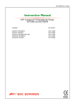
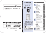
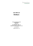
1.
2.
3.
4.
5.
6.
Speed indicator
Heater (bakeout band) switch
Standby button
Start/Stop button
Electrical supply LED
Fail LED
7.
8.
9.
10.
11.
Not used
Pump rotating LED (amber)
Pump speed >25% LED (amber)
Pump speed >50% LED (green)
Pump speed >75% LED (green)
Figure 1 - EXC120 Controller front panel
4
EXC Turbomolecular Pump Controllers
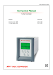
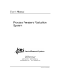
1.
2.
3.
4.
5.
6.
Speed indicator
Heater (bakeout band) switch
Standby button
Start/Stop button
Electrical supply LED
Fail LED
7.
8.
9.
10.
11.
12.
Emergency LED (EXC300M only)
Pump rotating LED (amber)
Pump speed >25% LED (amber)
Pump speed >50% LED (green)
Pump speed >75% LED (green)
Hours counter (EXC300 only)
Figure 2 - EXC300/300M Controller front panel (EXC300M shown)
EXC Turbomolecular Pump Controllers
5
Speed
The speed indicator has 4 LEDs which go on to indicate the rotational speed of the EXT pump.
Each LED goes on when the speed of the pump is above a certain value, represented as a
percentage of the full operating speed of the pump.
Refer to Figures 1 and 2: the bottom LED (8) goes on as soon as the pump rotor starts to rotate; the
next LED (9) goes on when the rotational speed is > 25% of full rotational speed. The first green
LED (10) goes on when the speed is > 50% of full rotational speed; the top LED (11) goes on when
the speed is > 75% of full rotational speed. Note that:
•
When the pump starts, the bottom LED goes on as soon as the pump rotor starts to rotate.
•
When the pump decelerates, the bottom LED goes off as soon as the pump speed falls to
below 10% of full rotational speed.
•
When only the bottom two LEDs are on, the pump speed is below 50% of its full rotational
speed and the Controller may trip into Fail condition, depending on how you have
configured the Controller (see Section 1.9.2).
•
When the pump is at Standby rotational speed, the top LED is off.
Emergency
This LED is only available on the EXC300M Controller. When the LED is on, this indicates an
Axial Emergency condition (refer to Section 1.9.3).
Fail
This LED is on when the Controller has tripped into Fail condition (refer to Section 1.9).
~
This LED is on when the Controller is connected to the electrical supply and the electrical supply
isolator on the rear of the Controller (see Figures 3 and 5) is switched on.
Hours counter
This counter is only available on the EXC300 Controller. The counter shows the total elapsed
time that the EXC300 Controller has operated an EXT pump.
1.4
Bakeout band control (EXC120/300/300M only)
The EXC120, 300 and 300M Controllers can be used to operate a bakeout band.
The Controller will switch on the electrical supply to the bakeout band when the Heater switch
on the front panel is switched on and the EXT pump is at Normal speed (refer to Sections 1.3 and
1.7.4).
6
EXC Turbomolecular Pump Controllers
1.5
Connection of an Active gauge
Note: If you connect a BOC Edwards Active gauge to operate the TMPI control input signal to the logic
interface, you cannot also use another signal to operate the TMPI control input.
You can directly connect a BOC Edwards Active gauge to the Controller (refer to Section 7 for
suitable gauges). For example:
•
You can use the set-point facility of an APG Active Pirani Gauge or an ATC Active
Thermocouple Gauge (which is used to measure system or backing pressure) to operate the
TMPI control input signal to the logic interface.
•
You can connect an AIM Active Inverted Magnetron Gauge and use the Controller TMP
Normal signal to switch the gauge on. This allows you to control the AIM Gauge without the
need to use an additional high pressure gauge (and its associated control equipment) to
interlock the operation of the AIM Gauge to system pressure.
Refer to Section 3.9 for details of the connection of an Active gauge to the Controller.
If you want to use any alternative gauges, you must connect the gauge to its associated control
equipment and then connect the set-point output of the control equipment to the logic interface.
1.6
Backing pump control (EXC120/300/300M only)
The EXC120, EXC300 and EXC300M Controllers can be used to control the operation of a backing
pump through a backing pump relay. The operation of this relay depends on how you have
configured the Controller to operate the vent-valve: refer to Sections 1.8 and 3.13.
1.7
Logic interface
1.7.1
Introduction
The rear panel of the Controller has a logic interface connector (see Figures 3 to 5) which you can
use to connect the Controller to your own equipment. The EXC120 and EXC120E Controllers
have a 17-way connector and the EXC300 and EXC300M Controllers have an 18-way connector.
Signals on the logic interface are of four types:
•
Electrical supplies
These are electrical supplies for accessories connected to your
pump; that is, the vent-valve and the air-cooler.
•
Control inputs
These are switch-type input signals which are used to control the
operation of the pumping system.
•
Status outputs
These outputs identify the status of the pump and the Controller.
•
Analogue output
The speed output provides an indication of the EXT pump speed.
Refer to Table 3 and to Figures 8 and 9 for detailed information about the logic interface pins and
their uses. A general description of the logic interface connections follows.
EXC Turbomolecular Pump Controllers
7
1.7.2
Electrical supplies
Two 24 V supplies are provided, as described below:
Vent-valve supply
This electrical supply is provided to operate a vent-valve fitted to your EXT pump or vacuum
system. The Controller automatically opens the valve when the speed of the pump falls to below
50% of full rotational speed (see Section 1.8). You can also configure the Controller to operate the
valve in other specific conditions: refer to Sections 1.8 and 3.13.
Air-cooler supply
This electrical supply is provided to operate an ACX air-cooler fitted to your EXT pump. The
electrical supply is on whenever the Controller is on. If your pump is water-cooled, you can use
this supply to operate a solenoid-valve to control the flow of water through the water-cooler.
1.7.3
Control inputs
Note: The Controller is supplied with wire links fitted to close the TMP and SYS Interlocks and to close
the Start/Stop input. The Controller cannot start the EXT pump if any of these three inputs are
open.
You can use these signals to control the operation of the EXT pump. The signals are switch-type
inputs in which two pins on the logic interface are linked (closed) when you want to set the
required signal and are unconnected (open) when you do not wish to set the signal.
Two of the inputs (Start/Stop and Standby) have the same functions as the buttons of the same
name on the Controller front panel (on EXC120, EXC300 and EXC300M Controllers). The other
two inputs are Interlocks and the Controller will only operate the EXT pump if both Interlocks
are closed (and if no Fail condition is present).
Start/Stop
Use the Start/Stop input to Start and Stop the EXT pump. Note that on the EXC120, EXC300 and
EXC300M Controllers, the signal is wired in series with the Start/Stop button on the front panel,
so you must close the Start/Stop input and press the Start/Stop button on the front panel to Start
the pump. To stop the pump, either open the input (that is, open the link between the
appropriate logic interface pins), or press the Start/Stop button again.
Standby
Close the Standby input to select pump Standby (refer to Section 1.3). Note that on the EXC120,
EXC300 and EXC300M Controllers, the Standby input is wired in parallel with the Standby
button on the front panel and you can use either the button or the input to select Standby at any
time.
8
EXC Turbomolecular Pump Controllers
TMP Interlock (TMPI)
Use the TMP Interlock to delay the start of the EXT pump until the backing pump has sufficiently
reduced the pressure in the vacuum system. You can therefore control the TMP Interlock either
by a timer or by a pressure switch in the backing pipeline of your system. Note that:
•
If the TMP Interlock is open when Start is selected, the Start LED on the Start/Stop button
will flash.
•
If the TMP Interlock is opened after Start is selected, but with the SYS Interlock open, the
Start LED will continue to flash.
•
If the TMP Interlock is opened after the EXT pump has started, the Controller will trip into
Fail condition.
SYS Interlock (SYSI)
Note: The EXC120E Controller does not have a backing pump relay.
Use the SYS Interlock to interlock the Controller to a system fail or control signal, for example, a
position switch on a door of the vacuum chamber or a start contactor for a backing pump.
When the SYS Interlock opens:
•
the backing pump relay opens (see Section 1.8)
•
the electrical supply to the vent-valve is switched off (see Section 1.8).
Note that:
•
If the SYS Interlock is open when Start is selected, the Start LED on the Start/Stop button will
flash.
•
If the SYS Interlock is opened after Start has been selected, but with the TMP Interlock open,
the Start LED will continue to flash.
•
If the SYS Interlock is opened after the EXT pump has started, the Controller will trip into
Fail condition. If the SYS Interlock then closes again, the vent option you have selected (refer
to Sections 1.8 and 3.13) will determine the operation of the backing pump relay and the
electrical supply to the vent-valve.
EXC Turbomolecular Pump Controllers
9
1.7.4
Status outputs
The Controller provides Normal and Fail status output signals (TMP Normal and TMP Fail)
through volt-free contacts on the logic interface connector. The EXC300M Controller also
provides an Axial Emergency condition signal (also on a volt-free contact). These signals can be
used to control devices in the pumping system or provide remote status output signals. The
signals operate as described below.
1.7.5
TMP Normal
TMP Normal is normally open and closes when the EXT pump
speed reaches the Normal speed setpoint. The Normal speed
setpoint is determined by a potentiometer on the top of the
Controller. The Controller is supplied with the potentiometer
adjusted so that the Normal speed setpoint is 80% of full rotational
speed. You can adjust the Normal speed setpoint as described in
Section 3.11.
TMP Fail
TMP Fail is normally closed and opens when the Controller trips
into Fail condition (see Section 1.9).
Axial Emergency
(EXC300M only)
Axial Emergency is normally closed and opens when an Axial
Emergency is detected (see Section 1.9.3).
Analogue outputs
The Pump Speed analogue output signal is proportional to EXT pump speed. Connect the
output to a suitable meter or indicator to display the pump speed or connect the output to your
control equipment (for example, to operate other components in the pumping system at preset
EXT pump speeds).
1.8
Vent-valve control
1.8.1
Introduction
Notes: 1.
2.
The EXC120E Controller does not have a backing pump relay.
The vent option factory settings are shown in Table 4.
Provided that the SYS Interlock is closed: if the Controller electrical supply fails, the Controller
maintains the electrical supply to the vent-valve until the pump speed falls to below 50% of full
rotational speed. The Controller then switches off the vent-valve electrical supply and opens the
backing pump relay. This feature of the Controller cannot be reconfigured.
10
EXC Turbomolecular Pump Controllers
However, you can use the configuration DIP switches on the Controller (refer to Section 3.13) to
select any one of (or any combination of) the following options:
•
Vent on Stop (Stop selected either by the front-panel button or the Start/Stop input on the
logic interface).
•
Vent on Fail condition.
•
Vent on Axial Emergency condition (only available on the EXC300M Controller: see
Section 1.9.3).
When a selected vent option condition is detected, the Controller:
1.8.2
•
waits approximately 2 seconds, to allow a vacuum system isolation-valve (if fitted) to close,
•
then switches off the electrical supply to the vent-valve,
•
then opens the backing pump relay.
Vent on Stop
Note: If the SYS Interlock opens, a Fail condition will occur and the Controller will switch off the
vent-valve electrical supply: see Sections 1.9.1 and 3.13.
Vent on Stop selected
When you switch on the Controller, the vent-valve electrical supply remains off until Start is
selected. Provided that the SYS Interlock is closed, the Controller switches the vent-valve
electrical supply on when Start is selected.
If Stop is then selected, the Controller switches the vent-valve electrical supply off again.
Vent on Stop not selected
When you switch on the Controller, the vent-valve electrical supply remains off until Start is
selected. Provided that the SYS Interlock is closed, the Controller switches the vent-valve
electrical supply on when Start is selected.
If Stop is then selected, the EXT pump will decelerate. The vent-valve electrical supply will
remain on until the pump speed falls to below 50% of full rotational speed, at which point the
vent-valve electrical supply will be switched off.
1.8.3
Vent on Fail and Vent on Axial Emergency
Note: The Vent on Axial Emergency option is only available on the EXC300M Controller.
If the Controller is configured to Vent on Fail or Vent on Axial Emergency, the Controller will
switch off the vent-valve electrical supply as soon as Fail condition or Axial Emergency
condition is detected.
EXC Turbomolecular Pump Controllers
11
1.9
Controller Fail conditions
1.9.1
General
The Controller will trip into Fail condition if any of the following occurs:
•
The TMP or SYS Interlock opens while the EXT pump is operating (see Note 1 below).
•
The EXT pump does not reach 50% of full rotational speed within a preset time after it starts
(the time set by the adjustable Internal Timer: see Sections 1.9.2 and 3.12).
•
The EXT pump speed falls to below 50% of its full rotational speed (see Note 2 below).
•
The EXT pump speed is too high (above 1.07% of full rotational speed).
•
The pump-to-controller cable is disconnected while the EXT pump is operating.
When the Controller trips into Fail condition, the electrical supply to the EXT pump-motor is
switched off, the TMP Fail status output signal on the logic interface opens and (on the EXC120,
EXC300 and EXC300M Controllers) the Fail LED on the front panel goes on. The operation of the
vent-valve and backing pump relay depends on how you have configured the Controller (refer
to Sections 1.8 and 3.13). To reset the Controller after Fail condition, refer to Section 4.9.
Notes:
1.9.2
1.
If the Controller trips into Fail condition because the SYS Interlock has opened, the
Controller will switch off the vent-valve electrical supply and (for the EXC120, EXC300
and EXC300M Controllers only) will open the backing pump relay. The operation of the
vent-valve in other Fail conditions depends on how you have configured the Controller:
refer to Sections 1.8 and 3.13.
2.
If you enable the Internal Timer (see Sections 1.9.2 and 3.13.2), the Controller will trip into
Fail condition only after the preset time has elapsed.
Internal Timer
Note: The Internal Timer starts when the Controller starts the EXT pump, not when Start is selected
(either by the front-panel button or the logic interface Start/Stop input). For example, if the Start
button is pressed to start the pump when the TMP Interlock is open, the Internal Timer will only
start when the Interlock closes and the Controller starts the pump.
The Internal Timer has two functions:
Firstly, when the EXT pump is started by the Controller, the Internal Timer in the Controller also
starts. If the EXT pump does not reach 50% of full rotational speed within the preset time
measured by the timer, the Controller will trip into Fail condition. This function cannot be
disabled.
12
EXC Turbomolecular Pump Controllers
Secondly, you can configure the Controller to enable or disable the Internal Timer if the pump
speed falls during pump operation:
•
If you disable the Internal Timer, the Controller will trip into Fail condition as soon as the
pump speed falls to below 50% of full rotational speed.
•
If you enable the Internal Timer, the Internal Timer will start as soon as the pump speed falls
to below 50% of full rotational speed; the Controller will trip into Fail condition if the pump
speed is still below 50% of full rotational speed at the end of the preset time.
The Controller is supplied with the Internal Timer enabled and adjusted for a preset time of
8 minutes. You can adjust the timer for your application: refer to Section 3.12.
1.9.3
Axial Emergency (EXC300M only)
The EXT250M pump has sensors which detect the axial displacement of the pump rotor; the
outputs of these sensors are monitored by the Controller.
The Controller trips into Axial Emergency condition if:
•
The displacement of the rotor exceeds set limits for more than 2 seconds.
•
The displacement of the rotor repeatedly exceeds set limits (due to oscillation).
When the Controller trips into Axial Emergency condition, the electrical supply to the
pump-motor is switched off, the Emergency LED on the front panel goes on and the Axial
Emergency status output signal on the logic interface opens. The EXT250M pump
electromagnetic bearings remain active, although the rotor assembly may contact the safety
bearings if the axial loading exceeds the capabilities of the bearing drive.
1.10
Electrical connections
All electrical connections to the Controller are on the rear panel: see Figures 3 to 5.
EXC Turbomolecular Pump Controllers
13
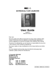
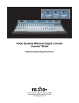
1.
Electrical supply isolator
6.
Active gauge connector
2.
3.
4.
5.
Earth (ground) stud
Bakeout band connector
EXT pump connector
Logic interface connector
7.
8.
9.
10.
Backing pump connector
Bakeout band fuse
Electrical supply fuse
Electrical supply connector
Figure 3 - Rear panel of the EXC120 Controller
14
EXC Turbomolecular Pump Controllers
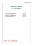
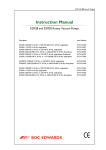
1.
2.
3.
4.
5.
6.
Electrical supply connector
EXT pump connector
Logic interface connector
Active gauge connector
Earth (ground) stud
Electrical supply fuse
Figure 4 - Rear panel of the EXC120E Controller
EXC Turbomolecular Pump Controllers
15
1.
2.
3.
4.
5.
6.
Electrical supply connector
Bakeout band connector
Earth (ground) stud
EXT pump connector
Active gauge connector
Logic interface connector
7.
8.
9.
10.
11.
Cooling-fan
Bakeout band fuse
Backing pump connector
Electrical supply isolator
Electrical supply fuse
Figure 5 - Rear panel of the EXC300/300M Controller
16
EXC Turbomolecular Pump Controllers
2
TECHNICAL DATA
Note: Unless otherwise specified, technical data in the following sections applies to all Controller models.
Refer to Table 1 for other technical data.
2.1
2.2
2.3
General
Performance data
See Table 1
Electrical data
See Table 1 and Sections 2.4, 2.6 and 2.7
Operating and storage data
Ambient operating temperature range
0 to 35 oC
Ambient storage temperature range
-20 to +40 oC
Maximum ambient operating humidity
10 to 95% RH (non-condensing
to DIN 40040)
Maximum operating altitude
3000 m
Mechanical data
Dimensions
Mass
2.4
See Figures 6 and 7
See Table 1
Logic interface
Relay contact rating (resistive load)
Remote control signals
1 A at 25 V d.c.
Control voltage: low (close)
Control voltage: high (open)
< 0.8 V d.c.
4 to 24 V d.c.
Maximum input current (at 24 V)
80 µA
Maximum output current (at 0 V d.c.)
Air-cooler electrical supply
Vent-valve electrical supply
Analogue EXT pump speed output
Output voltage
Maximum output current
EXC Turbomolecular Pump Controllers
160 µA
See Table 1
See Table 1
0 to +5 V d.c., proportional to EXT speed
5 mA
17
Parameter
EXC120
EXC120E
EXC300
EXC300M
Mass
2 kg
1.3 kg
4.6 kg
4.6 kg
Cooling
Natural
convection
Natural
convection
Forced air
Forced air
Electrical supply voltage
90 to 264 V a.c.
90 to 264 V a.c.
90 to 132 or
180 to 264 V a.c.
90 to 132 or
180 to 264 V a.c.
Electrical supply frequency
47 to 63 Hz
47 to 63 Hz
47 to 63 Hz
47 to 63 Hz
Maximum input power
400 VA
260 VA
700 VA
700 VA
Peak inrush current
27 A at 110 V a.c.
54 A at 240 V a.c
27 A at 110 V a.c.
54 A at 240 V a.c.
27 A at 110 V a.c.
54 A at 240 V a.c.
27 A at 110 V a.c.
54 A at 240 V a.c.
Compatible EXT pumps
EXT70, EXT250
EXT351, EXT501
EXT70, EXT250
EXT351, EXT501
EXT70, EXT250
EXT351, EXT501
EXT250M
110 W
110 W
290 W
290 W
Maximum output voltage
90 V peak to peak
90 V peak to peak
90 V peak to peak
90 V peak to peak
Switching frequency
32 kHz
32 kHz
32 kHz
32 kHz
Nominal commutation
frequency
600 Hz to 1.5 kHz
600 Hz to 1.5 kHz
600 Hz to 1.5 kHz
600 Hz to 1.5 kHz
Maximum commutation
frequency
1.07 x nominal
1.07 x nominal
1.07 x nominal
1.07 x nominal
Standby frequency
70% of nominal
70% of nominal
70% of nominal
70% of nominal
-
-
-
4.75 A
Maximum
-
-
-
26 V d.c
Minimum
-
-
-
10 V d.c.
+18 to +26 V d.c.
+18 to +26 V d.c.
+12 to +26 V d.c.
+12 to +26 V d.c.
100 mA
100 mA
100 mA
100 mA
+18 to +26 V d.c.
+18 to +26 V d.c.
+12 to +26 V d.c.
+12 to +26 V d.c.
80 mA
80 mA
80 mA
80 mA
90 to 132 or
180 to 264 V a.c.
-
90 to 132 or
180 to 264 V a.c.
90 to 132 or
180 to 264 V a.c.
150 W
-
150 W
150 W
EXT pump-motor
electrical supply
Maximum continuous
output power
Maximum continuous axial
bearing current
Axial bearing drive voltage
Air-cooler electrical supply
Voltage range
Maximum output current
Vent-valve electrical supply
Voltage range
Maximum output current
Bakeout band electrical
supply
Voltage range
Maximum power
Table 1 - Technical data
18
EXC Turbomolecular Pump Controllers
1.
2.
3.
4.
5.
Front panel
View from top
Clearance for cables
Clearance for ventilation
Panel cut-out
A
B
EXC120
EXC300/EXC300M
Figure 6 - EXC120, EXC300 and EXC300M Controller dimensions (mm)
EXC Turbomolecular Pump Controllers
19
1.
2.
3.
4.
5.
Front panel
Clearance for ventilation
View from top
Clearance for cables
Panel cut-out
Figure 7 - EXC120E Controller dimensions (mm)
20
EXC Turbomolecular Pump Controllers
2.5
Factory settings
Normal speed setpoint
80% of full rotational speed
Internal Timer
Vent options
8 min, enabled
See Table 4
Logic interface: pins linked
on the mating connector
EXC120/E
EXC300/M
2.6
Pins 9 & 10, pins 13 & 14, pins 15 & 16
Electrical connectors
Electrical supply connector socket type
CEE/IEC 320
Earth (ground) stud (on rear panel)
Backing pump relay connector *
M4
Socket type
Maximum voltage
Stak 200
250 V a.c.
Maximum current (a.c. r.m.s. inductive
load, 0.8 pf lagging)
15 A
Bakeout band connector *
Socket type
Maximum power
CEE/IEC/320
150 W
Active gauge connector
Signals on the connector pins
Socket type
See Figure 16 and Table 3
FCC68, 8-way
Manufacturer
Maximum power
Logic interface connector
Socket type (EXC120/120E/300M)
Socket type (EXC300)
Manufacturer
2.7
Pins 8 & 9, pins 12 & 13, pins 14 & 15
Western Electric
3W
MVSTBR 2,5/17-st5,08
MVSTBR 2,5/18-st5,08
Phoenix Combicon
Fuse ratings
Electrical supply fuse
EXC120/EXC120E
EXC300/EXC300M
Bakeout band fuse *
90 to 132 V a.c. electrical supply
180 to 264 V a.c. electrical supply
3.15 A, type T 20 mm
6.3 A, type T 20 mm
1 A, type F 20 mm
0.5 A, type F 20 mm
* Not applicable to the EXC120E Controller.
EXC Turbomolecular Pump Controllers
21
3
INSTALLATION
3.1
Unpack and inspect
Remove all packing materials and check the Controller.
If the Controller is damaged, notify your supplier and the carrier in writing within three days;
state the Item Number of the Controller together with your order number and your suppliers
invoice number. Retain all packing materials for inspection. Do not use the Controller if it is
damaged.
Check that your package contains the items listed in Table 2. If any of these items is missing,
notify your supplier in writing within three days.
If the Controller is not to be used immediately, store the Controller in suitable conditions as
described in Section 6.1.
Qty
1
1
1
1
1
1
1
Description
Check (✔)
EXC Controller
Backing pump relay electrical connector *
Security bracket for backing pump relay connector *
Logic interface electrical connector
Electrical supply cable
In-line filter ✝
Double-sided earth (ground) tab s
❏
❏
❏
❏
❏
❏
❏
* Not supplied with the EXC120E Controller.
✝ Only supplied with the EXC300 and EXC300M Controllers.
s
Only supplied with the EXC300M Controller; only needed if dual earth (ground)
bonding is required.
Table 2 - Checklist of contents
22
EXC Turbomolecular Pump Controllers
3.2
Fit the Controller
WARNING
The Controller contains electrolytic capacitors and, under certain fault conditions, may
emit dangerous fumes. Ensure that the Controller is operated in a well-ventilated area.
CAUTION
You must allow the correct clearances for air circulation and you must fit the EXC120E
Controller onto a thermally conductive surface. If you do not, the performance of the
Controller may be affected at high operating temperatures.
The Controller can be used on a bench-top or can be fitted in a rack or cabinet. You can operate
the EXC120, EXC300 and EXC300M Controllers in a horizontal position or in a vertical position
with the front panel at the top. You can operate the EXC120E Controller in a horizontal position
or in a vertical position with the side vents at the top.
When you fit a Controller in a rack or a cabinet, you must allow 15 mm clearance at the sides of
the Controller for air circulation and you must allow 75 mm clearance at the back of the
Controller for the cables. Do not obstruct the cooling-fan on the EXC300 and EXC300M
Controllers. The size of the front panel cut-out required and the location of the front panel fixing
holes for the EXC120, EXC300 and EXC300M Controllers are shown in Figure 6.
When you fit the EXC120E Controller, you must firmly fit the Controller onto a thermally
conductive material, for example aluminium or steel. The location of the bottom panel
fixing-holes are shown in Figure 7.
3.3
Introduction to Controller electrical connections
When you make the electrical connections to the Controller described in the following sections,
refer to Table 3 for full details of the logic interface connections and refer to Figures 8 and 9 which
show schematic diagrams of the electrical connections. Take note of the following:
•
The backing pump and bakeout band connectors are not available on the EXC120E
Controller.
•
The EXC120 and EXC120E Controllers have a 17-way logic interface connector. The EXC300
and EXC300M Controllers have an 18-way logic interface connector.
You must provide suitable strain-relief on the cables which you fit to the Controller.
EXC Turbomolecular Pump Controllers
23
Pin number
(EXC300/M)
1
Signal
Polarity*
Vent-valve electrical supply: 24 V
Signal
type
+
Pin number
(EXC120/E)
1
Supply
2
Vent-valve electrical supply: 0 V ◆
-
3
Air-cooler electrical supply: 24 V
+
2
3
Supply
{
■
4
Air-cooler electrical supply: 0 V
-
4
5
TMP Normal (closed when pump speed reaches
the Normal speed setpoint)
N/A
5
6
TMP Fail (open when fail condition exists)
N/A
7
Axial Emergency ✝ (open when Axial
Emergency condition exists)
N/A
8
Status output isolated common
N/A
9
+
Start/Stop: Close for Start
10
-
11
+
Standby: Close for Standby
{
{
■
■
12
13
14
15
16
TMPI (TMP Interlock):
Close for EXT pump operation
+
SYSI (SYS Interlock):
Close for backing pump operation
+
-
-
17
Pump speed
18
+
Status
outputs
6
-
7
Control
input
Control
input
Control
input
Control
input
Analogue
output
8
9
}
■
10
11
}
}
12
■
13
14
■
15
16
17
* + = positive, - = negative, N/A = not applicable.
✝ Only available on the EXC300M Controller.
◆ This supply line is raised to +24 V to de-energise the valve coil and vent the system.
■ The EXC Controller is supplied with these pins linked together on the mating connector.
Table 3 - Logic interface pins
24
EXC Turbomolecular Pump Controllers
A
B
Vacuum and control system
EXC Controller
L
N
E
Live electrical supply
Neutral electrical supply
Earth (ground) electrical supply
1.
2.
3.
4.
5.
6.
7.
External electrical supply
Earth (ground)
Electrical supply connector
Electrical supply isolator
Front panel Heater switch *
Bakeout band fuse *
Rear panel bakeout
band connector *
Bakeout band *
Backing pump
10.
11.
Backing pump relay *
Rear panel backing
pump relay connector *
Rear panel Active gauge
connector
Active gauge
Speed indicator
Logic interface connector
External SYS Interlock switch
8.
9.
12.
13.
14.
15.
16.
17.
18.
19.
20.
21.
22.
23.
24.
25.
External TMP Interlock switch
External Remote Standby switch
External Remote Start/Stop switch
TMP Normal output (normally open)
TMP Fail output (normally closed)
Not used
Vent-valve
Air-cooler
Remote indicator equipment
* Not available on the EXC120E Controller
Figure 8 - Schematic diagram of EXC120 & EXC120E Controller electrical connections
EXC Turbomolecular Pump Controllers
25
A
B
Vacuum and control system
EXC Controller
L
N
E
Live electrical supply
Neutral electrical supply
Earth (ground) electrical supply
1.
2.
3.
4.
5.
6.
7.
External electrical supply
Earth (ground)
Electrical supply connector
Electrical supply isolator
Front panel Heater switch
Bakeout band fuse
Rear panel bakeout
band connector
Bakeout band
Backing pump
10.
11.
Backing pump relay
Rear panel backing
pump relay connector
Rear panel Active gauge
connector
Active gauge
Speed indicator
Logic interface connector
External SYS Interlock switch
8.
9.
12.
13.
14.
15.
16.
17.
18.
19.
20.
21.
22.
23.
24.
25.
External TMP Interlock switch
External Remote Standby switch
External Remote Start/Stop switch
TMP Normal output (normally open)
TMP Fail output (normally closed)
Axial Emergency output
(normally closed) *
Vent-valve
Air-cooler
Remote indicator equipment
* EXC300M only
Figure 9 - Schematic diagram of EXC300 & EXC300M Controller electrical connections
26
EXC Turbomolecular Pump Controllers
3.4
Connect the electrical supply
WARNING
High voltages exist in the Controller when it is operating. Ensure that the Controller is
earthed (grounded) and observe all appropriate safety precautions for the safe installation
and handling of electrical equipment. If you do not, there will be a danger of injury or
death to people by electric shock.
Note: If you will use an EXC300 or EXC300M Controller in a commercial or residential environment,
you must fit the in-line filter supplied to the electrical supply connector on the Controller, then fit
the connector on the electrical supply cable to the filter.
1.
3.5
Connect the wires at one end of the electrical supply cable to a suitably rated and fused
electrical supply; if required, connect the wires to a suitably rated plug. Connect the wires as
follows:
•
Connect the green/yellow wire to earth (ground).
•
Connect the brown wire to the live electrical supply.
•
Connect the blue wire to the neutral electrical supply.
2.
On EXC120, EXC300 and EXC300M Controllers, ensure the electrical supply isolator on the
rear panel is in the off position.
3.
Fit the connector on the other end of the electrical supply cable to the electrical supply
connector on the rear of the Controller (see Figures 3 to 5).
Connect additional earth (ground) bonding (if required)
Protective earthing (grounding) for electrical safety of the EXC Controller, EXT pump and
accessories is provided by the electrical supply cables and connectors and the
pump-to-controller cable. However, additional earth (ground) bonding may be required to
improve the reliability of the system by reducing any effects of RFI (radio frequency
interference), particularly if the vacuum system is prone to high voltage discharges or other
radio frequency emissions.
Use good EMC (electromagnetic compatibility) practices and take note of the following EMC
earthing (grounding) guidelines to reduce the susceptibility of the system to RFI:
•
Connect the Controller, the EXT pump and the vacuum chamber to a common earth
(ground) point on the pumping system; this star earth (ground) is typically in the electrical
power distribution box.
•
Clamp the Controller earthing (grounding) terminal between the two lock-nuts provided on
the earth (ground) stud on the rear panel of the Controller.
•
Use suitable heavy duty cable or braid to ensure a low impedance bond to the earth (ground)
point (typically less than 0.1Ω for each leg of the star).
•
Use screened cable for all wiring to the logic interface connector. (The TAV5 vent-valve and
the ACX Air Cooler accessories are provided with screened cable.) Connect each screen to
the Controller earth (ground) stud to ensure that they are properly earthed (grounded).
EXC Turbomolecular Pump Controllers
27
3.6
Connect the EXT pump
Use a pump-to-controller cable (not supplied) to connect the Controller to the EXT pump. Fit the
connectors on the ends of the cable to the appropriate mating-halves on the Controller and on the
EXT pump. The connectors are polarised so you cannot fit a connector in the wrong orientation
and different connector types are used on the Controller and on the EXT pump, so you cannot fit
the cables the wrong way round.
3.7
Connect the backing pump (EXC120/300/300M only)
WARNING
Fit an earth (ground) wire to the backing pump relay electrical connector. If you do not,
the case of the Controller may become live if there is a wiring fault.
Note: To control a backing pump with the EXC120E, use the 24 V d.c. vent-valve electrical supply on the
logic interface to operate the pump through a suitable relay or contactor. This configuration will
provide identical control logic to that for the backing pump relay on the other Controllers.
The single-pole backing pump relay in the Controller provides a switching signal to control the
backing pump electrical supply; it does not provide a backing pump electrical supply. You can
use the backing pump relay to control the backing pump in one of two ways:
•
Directly, as shown in Figure 10
•
Through a contactor, as shown in Figure 11.
Use a suitably rated three-core cable to connect the backing pump to the Controller. If you use an
external contactor, ensure that the contactor is suitably rated for use in this way.
1.
Connect the wires of your backing pump cable to the appropriate pins of the backing pump
relay electrical connector (supplied). The pins of the connector are used as follows:
Pin
1
2
3
2.
28
Use
Live in
Switched live out
Earth (ground)
Connect the other end of your cable to the backing pump and/or the electrical supply, as
appropriate.
EXC Turbomolecular Pump Controllers
1.
EXC backing pump relay
2.
3.
Backing pump motor
EXC Controller
Figure 10 - Direct operation of the backing pump
1.
2.
3.
EXC Backing pump relay
Backing pump motor
EXC Controller
Figure 11 - Operation of the backing pump through a contactor
3.8
Connect the bakeout band (EXC120/300/300M only)
If you have fitted a bakeout band to the EXT pump, insert a suitably rated fuse into the bakeout
band fuse holder, then fit the connector on the bakeout band cable to the heater connector on the
rear of the Controller (see Figures 3 and 5).
EXC Turbomolecular Pump Controllers
29
3.9
Connect an Active gauge
Use a BOC Edwards Active gauge cable (available as an accessory: see Section 7) to connect a
BOC Edwards Active gauge to the Controller through the active gauge connector on the rear of
the Controller (see Figures 3 to 5).
If you want to use the set-point facility on an Active Pirani Gauge or Active Thermocouple
Gauge to operate the TMP Interlock, you must remove the link fitted to the TMP Interlock control
input on the logic interface; that is:
•
On EXC120 and EXC120E Controllers, remove the link between pins 12 and 13.
•
On EXC300 and EXC300M Controllers, remove the link between pins 13 and 14.
If you want to use the Controller TMP Normal relay to enable an Active Inverted Magnetron
Gauge, you must connect the TMP Normal relay isolated common line to the electrical supply
0 V line; that is:
3.10
•
On EXC120 and EXC120E Controllers, link pins 4 and 7.
•
On EXC300 and EXC300M Controllers, link pins 4 and 8.
Connect the logic interface to your equipment
CAUTION
Do not earth (ground) the logic interface 0 V line (pins 2 and 4). If you do, you will
provide an earth (ground) return path for any electrical fault in the pump-motor and this
could damage the Controller or your control equipment.
CAUTION
Do not connect voltages greater than 45 V to the logic interface. If you do, the Controller
will not comply with the low voltage safety recommendations of IEC 1010.
Note: If your backing pump will take more than 30 minutes to reduce the pressure in the vacuum chamber
to 1 mbar, we recommend that you use the TMP Interlock to delay the EXT pump Start until this
pressure is reached.
The Controller is supplied with a mating-plug for the logic interface connector. As supplied, this
mating-plug has three links fitted to close the TMP Interlock and SYS Interlock and to close the
Start/Stop input. If you want to use the Controller for stand-alone operation, you must fit this
mating-plug to the logic interface connector on the rear of the Controller (see Figures 3 to 5).
Use the appropriate pins on the mating-plug to connect your control equipment and accessories
to the Controller, as described in the previous sections and as shown in Table 3 and Figures 8 and
9. Note that, depending on how you want to use the Controller, you may have to remove the
factory fitted links from the mating-plug.
30
EXC Turbomolecular Pump Controllers
3.11
Adjust the Normal speed setpoint
Note: If you set the Normal speed setpoint to be more than 70% of full rotational speed, the TMP Normal
relay will open when you select Standby. The Controller is supplied with the Normal speed
setpoint adjusted to 80% of full rotational speed.
You can adjust the Normal speed setpoint (at which the TMP Normal relay will close: see
Section 1.7.4) between 65 and 95% of full rotational speed.
To adjust the Normal speed setpoint, use a small screwdriver to turn the SET POINT
potentiometer; an access hole is provided on the top cover of the Controller. Figure 12 detail A
shows the approximate Normal speed setpoint settings for different potentiometer adjustments.
Figure 12 - Top cover of the Controller
EXC Turbomolecular Pump Controllers
31
3.12
Adjust the Internal Timer
The Internal Timer can be adjusted between approximately 1 and 30 minutes. The Controller is
supplied with the Internal Timer adjusted to 8 minutes (see Section 1.9.2).
To adjust the Internal Timer, use a small screwdriver to turn the TIMER potentiometer; an access
hole is provided on the top cover of the Controller (see Figure 12).
1.
Turn the potentiometer fully anticlockwise; this position corresponds to the minimum time
of approximately 1 minute.
2.
Turn the potentiometer clockwise to set the required time; one full turn adds approximately
two minutes to the set time. For example, seven full turns give a set delay time of
approximately 15 minutes.
3.13
Configure the Controller
3.13.1
Introduction
The Controller has four DIP switches which can be used to configure the Controller for your
application. The DIP switches are on the top of the Controller (the CONFIG switches shown in
Figure 12). Set the DIP switches as described in the following sections.
3.13.2
Enable/disable the Internal Timer to monitor low pump speed
Note:
If you pump a high gas load with the Internal Timer enabled (DIP switch 1 set to the off position),
the EXT pump may stall before the Controller trips into Fail condition. Ensure that oil which
backstreams from the backing pipeline will not adversely affect your process.
Disable the Internal Timer to provide the greatest protection against backstreaming when Fail
condition occurs; as supplied, the Internal Timer is enabled.
Set DIP switch 1 to enable or disable the use of the Internal Timer when the pump rotational
speed falls to below 50% of full rotational speed during operation (see Section 1.9.2):
32
•
Set DIP switch 1 to 'on' to disable the timer. The Controller will then trip into Fail condition
as soon as the pump rotational speed falls to below 50% of full rotational speed.
•
Set DIP switch 1 to 'off' to enable the timer. The Internal Timer will then start as soon as the
pump rotational speed falls to below 50% of full rotational speed. If the pump speed remains
below 50% of full rotational speed after the preset time, the Controller will trip into Fail
condition.
EXC Turbomolecular Pump Controllers
3.13.3
Vent options
Note:
The Axial Emergency condition is only available on the EXC300M Controller. On other
Controllers, the position of DIP switch 2 can be ignored.
DIP switches 2 to 4 are used to select the vent-valve control options (refer to Section 1.8). Select
the required vent options as shown in Table 4.
Note however, that if the electrical supply to the Controller fails, the Controller will always
switch off the electrical supply to the vent-valve when the EXT pump speed falls to below 50% of
full speed (see Section 1.8.1).
DIP switch positions
2
(Vent on
Axial
Emergency)
3
(Vent on
Fail)
4
(Vent on
Stop)
Off
Off
Off
No optional vent selected: Vent when EXT pump
speed falls to below 50% of full speed after Stop is
selected
Off
Off
On
Vent on Stop
Off
On
Off
Vent on Fail and Vent when EXT pump speed falls
to below 50% of full speed after Stop is selected
Off
On
On
Vent on Fail and Vent on Stop
On ✝
Off ✝
Off ✝
On
Off
On
Vent on Axial Emergency* and Vent on Stop
On
On
Off
Vent on Axial Emergency* and Vent on Fail and
Vent when EXT pump speed falls to below 50% of
full speed after Stop is selected
On
On
On
Vent on Axial Emergency* and Vent on Fail and
Vent on Stop
Vent option(s) selected
Vent on Axial Emergency* and Vent when EXT
pump speed falls to below 50% of full speed after
Stop is selected
* Only available on the EXC300M Controller.
✝ Factory setting
Table 4 - Selection of vent-valve control options
EXC Turbomolecular Pump Controllers
33
4
OPERATION
4.1
Start-up
Note:
If you wish, you can start the backing pump and the EXT pump at the same time; the EXT pump
will not be damaged and can operate as an effective baffle. However, if the system pressure remains
too high for the EXT pump to reach 50% of full rotational speed in the preset time (set by the
Internal Timer), the Controller will trip into Fail condition: refer to Section 3.12 for adjustment of
the Internal Timer.
When Start is selected, if all Interlocks are closed, the Controller will switch on the electrical
supply to the EXT pump and the pump rotor will start to accelerate.
Use the following procedure to start up your system. This procedure assumes that you will
manually operate the vent-valve and the backing pump, however you can configure all EXC
Controllers to automatically operate the vent-valve and you can configure the EXC120, EXC300
and EXC300M Controllers to automatically operate the backing pump (refer to Sections 1.8
and 3.13.3).
4.2
1.
On EXC120, EXC300 and EXC300M Controllers, switch on the electrical supply isolator on
the rear of the Controller (see Figures 3 and 5).
2.
Close the vent-valve (if fitted).
3.
Start the backing pump.
4.
Start the EXT pump:
•
On the EXC120, EXC300 and EXC300M Controllers, press the Start button on the front
panel of the Controller (Figures 1 and 2, item 4) and (if you have connected your
equipment to the logic interface) close the Start/Stop input on the logic interface (see
Section 1.7.3).
•
On the EXC120E Controller, close the Start/Stop input on the logic interface (see
Section 1.7.3).
Standby
You can select Standby in one of two ways:
•
On the EXC120, EXC300 and EXC300M Controllers, select the Standby button on the front
panel of the Controller (Figures 1 and 2, item 3).
•
Use your control equipment to close the Standby input on the logic interface (that is, ensure
that the appropriate pins are linked: see Section 1.7 and Figures 8 and 9).
On the EXC120, EXC300 and EXC300M Controllers, the LED on the Standby button will go on
when the Standby mode is selected (either by the button or the logic interface).
If you select Standby when the pump is operating, the speed of the pump will be reduced to the
Standby speed. If you select Standby before you switch the pump on, the pump will run up to
Standby speed, not up to full speed.
34
EXC Turbomolecular Pump Controllers
4.3
Bakeout band control (EXC120/300/300M only)
Note: As described in Section 3.8, you must insert a suitably rated fuse into the bakeout band fuse holder
before you can use a bakeout band.
Press the Heater switch on the front panel of the Controller (Figures 1 and 2, item 2) to select the
bakeout band on.
The Controller will switch on the electrical supply to the bakeout band when the EXT pump
speed has reached the Normal speed setpoint. The electrical supply to the bakeout band will
switch off if the pump speed drops to below the Normal speed setpoint, if the Controller is
switched off, or if the Controller trips into Fail condition or Axial Emergency condition.
The LED on the Heater switch is on when the electrical supply to the bakeout band is on.
4.4
Operation with high inlet pressure
If the EXT pump inlet pressure rises, the power supplied by the Controller to the pump-motor
will increase to counteract the gas frictional load. The pump rotational speed will remain
constant until the Controller peak power level is reached; beyond this power level, the speed of
the pump will start to reduce.
If the pump speed falls to below 50% of its full rotational speed, the Controller may trip into Fail
condition, depending on how you configured the Controller (see Sections 1.8, 1.9 and 3.13).
Refer to the EXT pump instruction manual for the maximum allowable inlet pressure.
4.5
Operation with high pump temperature
Temperature sensors in the Controller and the EXT pump are monitored by the Controller. If the
Controller detects that the pump temperature is too high, the power supplied to the pump-motor
is reduced; the pump may not therefore be able to maintain full rotational speed if it is too hot.
If the pump speed falls to below 50% of its full rotational speed, the Controller may trip into Fail
condition, depending on how you configured the Controller (see Sections 1.8, 1.9 and 3.13).
Refer to the EXT pump instruction manual for the pump operating temperature ranges.
EXC Turbomolecular Pump Controllers
35
4.6
The hours counter (EXC300 only)
The EXC300 Controller has an hours counter (see Figure 13) which shows the number of hours
that the Controller has operated an EXT pump.
The hours counter has a 7-digit display (with no decimal point), on which the left-hand 5 digits
(2) show the whole numbers of hours and the right-hand two digits (3) show the tenths and
hundredths of hours. For example, if the hours counter shows 0010375", this indicates that the
EXT pump has been operating for 103 hours and 45 minutes.
Figure 13 - Hours counter (EXC300 only)
4.7
Normal shutdown
Use the following procedure to shut down your system. This procedure assumes that you will
manually operate the vent-valve and the backing pump, however you can configure all EXC
Controllers to automatically operate the vent-valve and you can configure the EXC120, EXC300
and EXC300M Controllers to automatically operate the backing pump (refer to Section 3.13).
1.
36
Select Stop:
•
On the EXC120, EXC300 and EXC300M Controllers, press the Start/Stop button on the
front panel of the Controller (Figures 1 and 2, item 4) or open the Start/Stop input on the
logic interface connector (see Section 1.7.3).
•
On the EXC120E Controller, open the Start/Stop input on the logic interface connector
(see Section 1.7.3).
2.
Open the vent-valve before the EXT pump speed is below 50% of full rotational speed.
3.
Switch off the backing pump.
EXC Turbomolecular Pump Controllers
4.8
Automatic shutdown after Fail condition
WARNING
If Start is selected, the Controller will automatically restart the EXT pump when the
electrical supply is restored after an electrical supply failure. Ensure that people cannot be
injured by the rotating rotor blades of the EXT pump.
The EXC120, EXC120E and EXC300 Controllers will automatically switch off the electrical
supply to the EXT pump if the Controller trips into Fail condition (see Section 1.9), though the
EXC300M Controller will continue to provide an electrical supply for the electromagnetic
bearings of the EXT250M pump.
If the SYS Interlock opens (see Section 1.7.3), the Controller will automatically open the
vent-valve and (on the EXC120, EXC300 and EXC300M Controllers) will automatically open the
backing pump relay. The operation of the vent-valve and backing pump in all other Fail
conditions depends on how you have configured the Controller: refer to section 3.13.
4.9
Reset the Controller after Fail condition
Note: You can only reset the EXC300M Controller after an Axial Emergency condition if the EXT pump
speed is below 10% of full rotational speed.
To reset a Fail condition, press the Start/Stop button (Figures 1 and 2, item 4) to select Stop, then
press it again, or (if you have connected your equipment to the logic interface) open the
Start/Stop input on the logic interface for a minimum time of 300 ms and then close the input.
4.10
Electrical supply failure
If the electrical supply to the Controller fails when the EXT pump is rotating:
•
The backing pump shuts down (due to the electrical supply failure).
•
The motor of the EXT pump is used as a generator and the electrical supply for the vent-valve
is maintained until the pump speed falls to 50% of full rotational speed, then the electrical
supply for the vent-valve is switched off.
•
EXC120, EXC120E and EXC300 Controllers will then shut down. On the EXC300M
Controller, the motor of the EXT pump will continue to act as a generator until pump speed
is reduced to approximately 10% of full rotational speed. The EXC300M Controller then
shuts down and the EXT250M pump rotor drops onto its safety bearings.
EXC Turbomolecular Pump Controllers
37
5
Maintenance
5.1
Safety
WARNING
Obey the safety instructions given below and take note of appropriate precautions. If you
do not, you can cause injury to people and damage to equipment.
•
A suitably trained and supervised technician must perform maintenance work.
•
Isolate the Controller and other components in the pumping system from the electrical
supply so that they can not be operated accidentally.
•
Dispose of components safely (see Section 6.2).
5.2
Replace a fuse
5.2.1
Introduction
If a fuse fails immediately after you have replaced it, determine the cause of the failure and
rectify the fault before you use the Controller.
5.2.2
Replace the electrical supply fuse
The electrical supply fuse is an integral part of the electrical supply socket on the rear of the
Controller (see Figures 3 to 5).
5.3.3
1.
Remove the electrical supply plug.
2.
Remove the fuse holder, remove and discard the failed fuse.
3.
Insert a new fuse of the correct rating (refer to Section 2.7) and refit the fuse holder.
Replace the bakeout band fuse (EXC120/300/300M only)
The bakeout band fuse is on the rear of the Controller (see Figures 3 and 5).
38
1.
Turn and pull out the fuse holder.
2.
Remove and discard the failed fuse and replace with a new fuse of the correct rating (refer to
Section 2.7).
3.
Refit the fuse holder.
EXC Turbomolecular Pump Controllers
5.4
Fault finding
If the Controller shuts down because of Fail condition, refer to the appropriate sections of this
manual to determine the cause of the Fail. If necessary, refer to the appropriate fault finding
section of the instruction manual supplied with the EXT pump.
5.5
Clean the Controller
If necessary, use a soft dry cloth to clean the exterior of the Controller.
If you need to clean the interior of the Controller, we recommend that you return the Controller
to your supplier or your nearest BOC Edwards Service Centre.
6
STORAGE AND DISPOSAL
6.1
Storage
Fit protective covers over the electrical connections and store the Controller in clean dry
conditions until required.
When required for use, prepare and install the Controller as described in Section 3 of this
manual.
6.2
Disposal
WARNING
Do not incinerate the Controller. If you do, you may cause injury to people.
Dispose of the Controller and any components safely in accordance with all local and national
safety and environmental requirements.
Do not incinerate the Controller. If the Controller is heated to very high temperatures,
dangerous gases may be emitted and internal components may explode.
EXC Turbomolecular Pump Controllers
39
7
SPARES AND ACCESSORIES
7.1
Introduction
BOC Edwards products, spares and accessories are available from BOC Edwards companies in
Belgium, Brazil, Canada, China, France, Germany, Israel, Italy, Japan, Korea, Singapore,
Switzerland, United Kingdom, U.S.A and a world-wide network of distributors. The majority of
these centres employ Service Engineers who have undergone comprehensive BOC Edwards
training courses.
Order spare parts and accessories from your nearest BOC Edwards company or distributor.
When you order, please state for each part required:
7.2
•
Model and Item Number of your equipment
•
Serial number (if any)
•
Item Number and description of the part.
Spares
Spare
Electrical supply cable (2 m length, unterminated)
Item Number
D385-01-102
Logic interface connector
EXC120/120E Controllers
EXC300/300M Controllers
D396-16-382
D396-15-062
Backing pump relay connector *
D396-14-026
* Not applicable to the EXC120E Controller
7.3
Accessories
7.3.1
Pump-to-controller cable
A pump-to-controller cable must be used with each pump. It is not supplied with the EXT pump
or the EXC Controller. The following cables are available:
Cable
Pump-to-controller cable, 1 m
Pump-to-controller cable, 3 m
Pump-to-controller cable, 5 m
40
Item Number
EXT70/250/351/501EXT250M
D396-18-010
D396-19-010
D396-18-030
D396-19-030
D396-18-050
D396-19-050
EXC Turbomolecular Pump Controllers
7.3.2
BX bakeout band (EXC120/300/300M only)
A BX bakeout band accelerates the degassing of the pump to enable it to achieve lower pressures.
It may also be used to protect the pump from condensation of contaminants. The bakeout bands
are available in 110-120 V or 220-240 V versions and may be powered from a connector on the
rear panel on the EXC120, EXC300 and EXC300M Controllers.
7.3.3
Bakeout band
BX70
Voltage
110 V
Item Number
B580-52-040
BX70
240 V
B580-52-060
BX250
BX250
110 V
240 V
B580-52-041
B580-52-061
BX351
110 V
B580-52-042
BX351
BX501
240 V
110 V
B580-52-062
B580-52-044
BX501
240 V
B580-52-064
TAV vent-valve
A solenoid-operated vent-valve is available for system venting. The valve is 24 V d.c. 2 W,
normally-open, and can be operated automatically from the EXC Controller. The solenoid-valve
is fitted in place of the manual vent-valve, or alternatively can be fitted with an adaptor (supplied
with the valve) and used with any suitable NW10 flanged port on your vacuum system.
7.3.4
Product
Item Number
TAV5 vent-valve
B580-66-010
ACX air-cooler
An ACX air-cooler can be fitted to the EXT pump and can be operated automatically from the
EXC120, EXC300 and EXC300M Controllers. However, please refer to Section 3 of the
instruction manual for the EXT pump to check the suitability of air cooling in a particular
application.
Air-cooler
ACX70
ACX250
ACX350/500
EXC Turbomolecular Pump Controllers
Item Number
B580-53-050
B580-53-150
B580-53-200
41
7.3.5
Active vacuum gauges
A number of Active vacuum gauges which can interface directly to the EXC Controllers are
available. The following are examples of suitable gauges and accessories:
Description
Item Number
APG-M-NW16 Active Pirani Gauge
D021-71-000
APG-L-NW16 Active Pirani Gauge
AIM-S-NW25 Active Inverted Magnetron Gauge
D021-73-000
D145-45-000
ATC-E Active Thermocouple Gauge
D351-08-000
1
ATC-D /8 inch NPT Thermocouple Gauge Tube
1
42
D351-12-000
ATC-M /8 inch NPT Thermocouple Gauge Tube
D351-13-000
Active Gauge Cable, 0.5 m long
Active Gauge Cable, 1 m long
D400-01-005
D400-01-010
Active Gauge Cable, 3 m long
D400-01-030
EXC Turbomolecular Pump Controllers
8
ENGINEERING DIAGRAMS
To assist in fault finding (refer to Section 5), the connections between the Controller and the EXT
pump are shown in Figures 14 and 15.
The Active Gauge connector (which is specific to the EXC Controller) is shown in Figure 16.
A
B
C
D
EXT pump
EXT connector on cable
EXC connector on cable
EXC Controller
1.
2.
3.
4.
5.
6.
DC motor
Speed set resistor
Hall effect device 1
Hall effect device 2
Hall effect device 3
Pump temperature sensor
Figure 14 - EXC120/120E/300 Controller to EXT pump connections
EXC Turbomolecular Pump Controllers
43
A
B
C
D
EXT pump
EXT connector on cable
EXC connector on cable
EXC Controller
1.
2.
3.
4.
5.
6.
7.
8.
DC motor
Speed set resistor
Hall effect device 1
Hall effect device 2
Hall effect device 3
Pump temperature sensor
Magnetic bearing stator
Position sensor
Figure 15 - EXC300M Controller to EXT pump connections
44
EXC Turbomolecular Pump Controllers
Figure 16 - Active Gauge connector
Pin
1
2
3
4
5
6
7
8
Signal
Power supply +24 V d.c.
Power supply 0 V d.c.
Not used
Gauge identification signal
Not used
Controller enable (equivalent to TMP Interlock)
Gauge enable (equivalent to TMP Normal)
Not used
Table 5 - Active Gauge connector pins
EXC Turbomolecular Pump Controllers
45
(This page deliberately left blank)
46
EXC Turbomolecular Pump Controllers