1
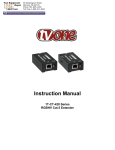
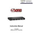
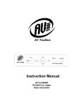
99 Washington Street Melrose, MA 02176 Phone 781-665-1400 Toll Free 1-800-517-8431 Visit us at www.TestEquipmentDepot.com Instruction Manual AVT-3155A PC to Video Scan Converter Table of Contents 1.0 Introduction 2 2.0 Specifications 4 3.0 Checking Package Contents 4 4.0 Connecting the Hardware 4 5.0 Operating The Unit 6 6.0 Troubleshooting 6 7.0 Limited Warranty 6 8.0 Regulatory Compliance 7 9.0 Contact Information 8 Test Equipment Depot - 800.517.8431 - 99 Washington Street Melrose, MA 02176 TestEquipmentDepot.com 1.0 INTRODUCTION Thanks for purchasing this product from the AV Toolbox Division of TV One. The AVT-3155A PC to Video Scan Converter is designed to convert a variety of computer images, ranging from 640x480 to 1600x1200 pixels, to interlaced NTSC or PAL Video. The AVT-3155A provides both Composite and S-Video output signals, and is ideal for use in applications requiring the viewing of PC images on a standard television monitor. This is but one of our complete range of video and audio products. 1.1 Liability Statement Every effort has been made to ensure that this product is free of errors. TV One cannot be held liable for the use of this hardware or any direct or indirect consequential damages arising from its use. It is the responsibility of the user of the hardware to check that it is suitable for his/her requirements and that it is installed correctly. All rights reserved. No parts of this manual may be reproduced or transmitted by any form or means electronic or mechanical, including photocopying, recording or by any information storage or retrieval system without the written consent of the publisher. TV One reserves the right to revise any of its hardware and software following its policy to modify and/or improve its products where necessary or desirable. This statement does not affect the legal rights of the user in any way. All third party trademarks and copyrights are recognised. The TV One logo, AV Toolbox logo, TV One-task and CORIO are the registered Trademarks of TV One. All other trademarks are the property of their respective holders. 1.2 Features Automatically down converts incoming PC images to NTSC or PAL. Support high resolution PC inputs up to UXGA (1600x1200@60Hz). Scales PC video to Composite/S-Video. Supports both NTSC/PAL Television Standards. Provision for Image Overscan and Underscan. Easy to install and simple to operate. Small, palm size footprint. 2 1.3 Getting the Best Results There are many factors affecting the quality of results when scaling video signals. Some basic precautions will ensure the best possible performance from your Scan Converter. Output display device – The quality of the output signal will depend largely upon the type and quality of display device used. For instance, some video projectors just look better than others. Distance between the Scan Converter and the display device – This plays a major role in the final result. Long distances are possible, but special measures should be taken in order to avoid cable losses. These include using high quality (coax-type) VGA cables. Line amplifiers may also be necessary. Output connection cables – Low quality cables are susceptible to interference. They degrade signal quality due to poor matching and cause elevated noise levels. Therefore, cables should be of the best quality. Coax-type computer cables are recommended because of their superior internal shielding characteristics. Interference from nearby electrical devices – These can have an adverse effect on signal quality. For example, an older computer monitor often emits very high electromagnetic fields that can interfere with the performance of video equipment in its proximity. 3 2.0 SPECIFICATIONS Input Format Input Signal Types Output Format Output Signal Types Input Connector Output Connectors Device Control Output Adjustments Weight Dimensions–HxWxD Power Source 3.0 Standard PC Video VGA (640x480) through UXGA (1600x1200) S-Video (SV) or Composite Video (CV) NTSC or PAL Standard 1x HD-15 Composite Video via 1x RCA, S-Video via 1x4 Pin DIN Auto PC resolution sensing, Manual NTSC/PAL Selection Standard Image, Overscan, Underscan 0.22lbs (100g) 0.9”x3.9”x2.5” (24x100x64mm) 100~240VAC to 5VDC Adapter CHECKING PACKAGE CONTENTS Before attempting to use this unit, please check the packaging and make certain the following items are contained in the shipping carton: 1x AVT-3155A PC to Video Scan Converter 1x 100~240VAC to 5VDC Power Adapter 1x User Manual Note: Please retain the original packing material should the need ever arise to return the unit. If you find any items are missing, contact your reseller or TV One immediately. Have the Model Number, Serial Number and Invoice available for reference when you call. 4.0 CONNECTING THE HARDWARE The first step is to connect a PC video source to the input of the AVT-3155A Scan Converter and then connect its output to a display device and lastly connect the AC to DC converter. The drawings below show the locations of the input, outputs, power switch and power connector. The Power Switch and Power “On” LED are located on the top of the unit. 4 Test Equipment Depot - 800.517.8431 - 99 Washington Street Melrose, MA 02176 TestEquipmentDepot.com The NTSC/PAL switch on the front of the AVT-3155A allows selection of the desired television standard. The input side of the AVT3155A is where the HD-15 PC input connector and the 5VDC Power adapter connectors are located. 4.1 The output side of the AVT-3155A is where the S-Video, Composite Video connectors and the Overscan/Underscan switch are located. Connecting the Input Before using the AVT-3155A, make certain that the PC is producing a picture on its regular monitor. If it is, disconnect the monitor and connect an HD-15 to HD15 cable between the output of the PC and the input of the AVT-3155A. If improper operation of the unit occurs and the unit has power, the most likely cause of the problem is a PC output resolution higher than 1600x1200 or the use of a wrong input cable. 4.2 Connecting the Output Determine if the display you will be using accepts an S-Video input or a Composite Video input or both. If you have a choice, you’ll want to use the SVideo input as it will produce the best picture in most cases. Next, position the PAL/NTSC switch to the proper position. In the United States you will generally set the switch to the NTSC position, elsewhere you will set the switch to PAL. 4.3 Connecting Power to the Unit The Scan Converter is shipped with a Power Adapter to convert 100~240VAC@50-60Hz to 5VDC. Connect the DC Output Cord from the Power Adapter to the back of the unit and then plug the Power Adapter into an AC 5 Receptacle. When the unit’s front panel Power Switch is pressed, the Power LED indicator will illuminate. 5.0 OPERATING THE UNIT Once the AVT-3155A is connected to a PC and an appropriate display, apply power and the unit will automatically detect the resolution being output by the PC. You select the proper television standard (NTSC/PAL) and an image will appear on the display. If you wish to make the display’s image smaller or larger, you can move the Underscan/Overscan switch as required. There are no other adjustments required to the AVT-3155A PC to Video Scan Converter. 6.0 TROUBLESHOOTING Other than checking for faulty cables and for a lighted power LED, the only common problem would be choosing a wrong television standard setting. Make certain you have the N TSC/PAL s witch set correctly. Finally, make certain that the PC is not outputting a signal greater than 1600x1200 (UXGA) by reconnecting your monitor and checking the PC’s output resolution on the monitor. If it is greater than 1600x1200, readjust the output to UXGA. After trying the above suggestions sh ould the problem still persist, contact your dealer for additional suggestions before contacting TV One. Should the dealer’s technical personnel be unable to assist you, contact TV One via our support website: http://tvone.crmdesk.com. Create a technical support request on the site and our support team will respond within a short period of time. 7.0 LIMITED WARRANTY LIMITED WARRANTY – With the exceptions noted in the next paragraph, AV Toolbox warrants the original purchaser that the equipment it manufactures or sells will be free from defects in materials and workmanship for a period of one year from the date of purchase. Should this product, in AV Toolbox’s opinion, prove defective within this warranty period, AV Toolbox, at its option, will repair or replace this product without charge. Any defective parts replaced become the property of AV Toolbox. This warranty does not apply to those products which have been damaged due to accident, unauthorized alterations, improper repair, modifications, inadequate maintenance and care, or use in any manner for which the product was not originally intended. Items integrated into AV Toolbox products that are made by other manufacturers, notably computer hard drives and liquid crystal display panels, are limited to the term of the warranty offered by the respective manufacturers. Such specific warranties are available upon request to AV Toolbox. If repairs are necessary under this warranty policy, the original purchaser must obtain a Return Authorization Number from AV Toolbox and return the product to a location 6 designated by AV Toolbox, freight prepaid. After repairs are complete, the product will be returned, freight prepaid. LIMITATIONS - All products sold are "as is" and the above Limited Warranty is in lieu of all other warranties for this product, expressed or implied, and is strictly limited to one year from the date of purchase. AV Toolbox assumes no liability to distributors, resellers or end-users or any third parties for any loss of use, revenue or profit. AV Toolbox makes no other representation of warranty as to fitness for the purpose or merchantability or otherwise in respect of any of the products sold. The liability of AV Toolbox with respect to any defective products will be limited to the repair or replacement of such products. In no event shall AV Toolbox be responsible or liable for any damage arising from the use of such defective products whether such damages be direct, indirect, consequential or otherwise, and whether such damages are incurred by the reseller, end-user or any third party. 8.0 REGULATORY COMPLIANCE The AVT-3155A has been tested for compliance with appropriate FCC and CE rules and regulations. The Power Adaptor/Supplies have been tested for compliance with appropriate UL, CUL, CE, PSE, GS Rules, Regulations and/or Guidelines. These Products and Power Adapters are RoHS Compliant. 9.0 CONTACT INFORMATION Should you have questions or require assistance with this product in areas not covered by this manual, please contact TV One at the appropriate location. 7 Test Equipment Depot - 800.517.8431 - 99 Washington Street Melrose, MA 02176 TestEquipmentDepot.com