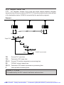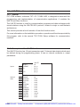
1
Looking for more information?
Visit us on the web at http://www.artisan-scientific.com for more information:
• Price Quotations • Drivers· Technical Specifications. Manuals and Documentation
Artisan Scientific is You~ Source for: Quality New and Certified-Used/Pre:-awned ECJuiflment
• Fast Shipping and DelIve1y
• Tens of Thousands of In-Stock Items
• Equipment Demos
• Hundreds of Manufacturers Supported
• Leasing / Monthly Rentals
Service Center Repairs
Experienced Engineers and Technicians on staff in our
State-of-the-art Full-Service In-House Service Center Facility
• Consignment
InstraView Remote Inspection
Remotely inspect equipment before purchasing with our
Innovative InstraView-website at http://www.instraview.com
We bUy used equipment! We also offer credit for Buy-Backs and Trade-Ins
Sell your excess. underutilized. and idle used equipment. Contact one of our Customer Service Representatives todayl
Talk to a live person: 88EM38-S0URCE fB88-887-68721 I Contact us by email: [email protected] I Visit our website: http://www.artisan-scientific.com
FIPWAY
Connection kit
Contents
___________________________________________________________________________
Section
Page
1 Introduction
1/1
1.1
Preface
1/1
1.2
Documentation structure
1/1
1.3
Description of the FIPWAY connection Kit
1.3-1 General
1.3-2 Functions
1/2
1/2
1/2
1.4
Physical description
1.4-1 TSX MPM 100 module
1.4-2 TSX FPP 20 PCMCIA card
1.4-3 TSX FP CG 010 connection cable
1.4-4 TSX FP ACC4 junction box
1/3
1/3
1/3
1/4
1/4
1.5
FIPWAY link characteristics
1/5
1.6
Hardware installation
1.6-1 Mounting the module in racks
1.6-2 Mounting the PCMCIA card :
1/6
1/6
1/7
2 Software installation
2.1
2.2
Software installation
2.1-1 General
2.1-2 The XTEL-CONF station tool
2/1
2/1
2/1
2/1
COM Service
2/2
2.2-1 General
2/2
2.2-2 Operating principles
2/3
2.2-3 Common memory organization
2/4
2.2-4 Common word configuration
2/5
2.2-5 COM words in multinetwork operation
2/6
2.2-6 System bits and words
2/7
2.2-7 Application example
2/9
___________________________________________________________________________
S/1
Artisan Scientific - Quality Instrumentation ... Guaranteed | (888) 88-SOURCE | www.artisan-scientific.com
FIPWAY
Connection kit
Contents
___________________________________________________________________________
Section
2.3
UNI-TE service
2.3-1 General
2.3-2 Services supported by PLCs
Page
2/11
2/11
2/12
2.4 Application-to-application communication
2.4-1 Point-to-point messages
2.4-2 Broadcast messages
2.4-3 Point-to-point message example
2/13
2/13
2/14
2/15
2.5
Priority communication - telegram
2.5-1 General
2.5-2 Telegram programming
2.5-3 Example of a telegram
2/17
2/17
2/19
2/20
2.6
PLC scan cycle
2/23
2.7
Multinetwork configuration
2.7-1 Configuration of FIPWAY, ETHWAY, MAPWAY or
TELWAY modules
2.7-2 PLC scan time
2/24
3 Maintenance
2/24
2/25
3/1
3.1
Maintenance
3.1-1 Indicator lamps
3.1-2 Indicator lamps on the TSX MPM 100 host module
3.1-3 Indicator lamps on the TSX FPP 20 PCMCIA card
3.1-4 Troubleshooting
3/1
3/1
3/1
3/1
3/2
3.2
Data rate control (message handling)
3/4
___________________________________________________________________________
Artisan
S/2 Scientific - Quality Instrumentation ... Guaranteed | (888) 88-SOURCE | www.artisan-scientific.com
FIPWAY
Connection kit
Contents
___________________________________________________________________________
Section
Page
4 Technical specifications
4.1
4/1
Performance
4/1
4.1-1 Transfer time for application-to-application common words 4/1
4.1-2 Request Transaction Time
4/2
4.1-3 Uploading application programs
4/3
4.1-4 Telegram Transfer Time
4/4
4.1-5 FIPWAY / FIPWAY Bridge Transit Time
4/5
5 Appendix
5/1
5.1
Requests supported by model 40 PLCs
5.1-1 Standard requests
5.1-2 Specific requests
5/1
5/1
5/2
5.2
Standard requests
5.2-1 Read a bit
5.2-2 Read a word
5.2-3 Read objects
5.2-4 Write a bit
5.2-5 Write a word
5.2-6 Write objects
5.2-7 RUN
5.2-8 STOP
5/3
5/3
5/4
5/5
5/10
5/11
5/12
5/15
5/16
5.3
Specific read requests
5.3-1 Read a system bit
5.3-2 Read the memory image of an I/O module
5.3-3 Read a constant word
5.3-4 Read a system word
5.3-5 Read a COM word
5.3-6 Read a timer
5.3-7 Read a monostable
5.3-8 Read a counter
5.3-9 Read a register
5/17
5/17
5/18
5/20
5/21
5/22
5/23
5/24
5/25
5/26
___________________________________________________________________________
S/3
Artisan Scientific - Quality Instrumentation ... Guaranteed | (888) 88-SOURCE | www.artisan-scientific.com
FIPWAY
Connection kit
Contents
___________________________________________________________________________
Section
5.3-10 Read
5.3-11 Read
5.3-12 Read
5.3-13 Read
Grafcet steps
a double word
a constant double word
a Grafcet step
Page
5/27
5/28
5/29
5/30
5.4
Specific write requests
5.4-1 Write a system bit
5.4-2 Write the memory image of an I/O bit
5.4-3 Write a system word
5.4-4 Write a COM word
5.4-5 Write a timer preset
5.4-6 Write a monostable preset
5.4-7 Write the preset value of a counter
5.4-8 Write a register input word
5.4-9 Write a double word
5/31
5/31
5/32
5/33
5/34
5/35
5/36
5/37
5/38
5/39
5.5
Text block reminders
5.5-1 Description
5.5-2 Communication by TXT text block
5.5-3 Communication by SYS text block
5.5-4 Table layout
5/40
5/40
5/40
5/44
5/45
5.6
UNI-TE function reminders
5.6-1 General
5.6-2 Description of the UNI-TE function
5.6-3 Input parameters
5.6-4 Internal data
5.6-5 Error list
5.6-6 Using the UNI-TE function
5.6-7 Example
5/46
5/46
5/46
5/47
5/48
5/49
5/51
5/52
5.7
List of documents to which reference is made
5/53
___________________________________________________________________________
Artisan
S/4 Scientific - Quality Instrumentation ... Guaranteed | (888) 88-SOURCE | www.artisan-scientific.com
Section 11
Introduction
1 Introduction
1.1
Preface
The MPM 100 module operating conditions :
To use the module requires at least the XTEL V52 software workshop updated with
catalogue product TSX R CTG V52E.
When used in PL7-NET multi-network architecture it requires a setup version of V6 or
greater.
The network diagnostics tool NETDIAG accepts module MPM 100 from V6 onwards.
PL7-3 software version have to be 5.8 or more.
1.2
Documentation structure
This documentation is designed for users who wish to set up a FIPWAY network. The
documentation required is the following :
TSX DR FPW E reference manual which describes :
• FIPWAY / FIPIO network operating principles,
• Network installation and checking principles,
• Operating, adjustment and diagnostics functions,
• Technical characteristics of FIPWAY / FIPIO networks,
• A glossary of technical terms specific to networks.
TSX DM FPM 100E user manual (this document) which describes:
• The product,
• Setting up and connecting on the network,
• Network performance,
• Operation with Telemecanique software,
• Network diagnostic functions.
___________________________________________________________________________
1/1
Artisan Scientific - Quality Instrumentation ... Guaranteed | (888) 88-SOURCE | www.artisan-scientific.com
1.3
Description of the FIPWAY connection Kit
1.3-1 General
The FIPWAY TSX FPM 100 connection kit comprises :
• a TSX MPM 100 host module
• a TSX FPP 20 FIPWAY PCMCIA card
• TSX FP CG 010 connection cable
• TSX ACC 04 junction box
• TSX DM FPM 100E user manual
The TSX MPM 100 module is an intelligent module from the TSX series 7 range of PLCs.
It can be installed in Model 40 PLCs (TSX and PMX 47-40 .....107-40). It provides
communication functions between the PLC and any other devices on an X-WAY
architecture.
It can be fitted with a TSX FPP 20 PCMCIA card for connection to a FIPWAY network.
M 100
TSX MP
RUN
DEF
FIPWAY/FIPIO
•••
•• • • •
•
•••••• • • • •
•••• • • • •
••
1.3-2 Functions
The TSX MPM 100 module is fitted with the TSX FPP 20 PCMCIA card for connection
to the FIPWAY network in accordance with the FIP standard and is integrated in the XWAY communication architecture. The network number and the station number are set
by rotating switches integrated in the PCMCIA card (see hardware setup).
___________________________________________________________________________
1/2 Scientific - Quality Instrumentation ... Guaranteed | (888) 88-SOURCE | www.artisan-scientific.com
Artisan
Introduction
1.4
1
Physical description
1.4-1 TSX MPM 100 module
The module is a single format module which can be inserted in a slot in the PLC base
configurations.
The module comprises the following :
1 Metal box physically protecting the electronic circuits and providing protection
against radiated interference.
M 100
TSX MP
2 RUN indicator lamp (green), lit when the
module is running.
RUN
2
DEF
3
3 DEF (ERRor) indicator lamp (red), lit
when there is a module fault.
1
4 Slot for TSX FPP 20 PCMCIA card.
5 Two fixing screws which attach the
module in the rack and ensure electrical
continuity of the ground connection.
4
5
1.4-2 TSX FPP 20 PCMCIA card
The PCMCIA card is made up of an extended type lll format metal box and comprises
the following :
1 Circular switches for coding the network
and station number.
2 ERR indicator lamp (red), lit when there
is a fault in the FIPWAY PCMCIA card
3 COM indicator lamp (yellow), indicates
the transmission/reception of data on
the FIPWAY network.
1
4 Connector for connection to FIPWAY
network.
2
5 Removable cover for mounting the
PCMCIA card in the host module.
3
4
5
___________________________________________________________________________
1/3
Artisan Scientific - Quality Instrumentation ... Guaranteed | (888) 88-SOURCE | www.artisan-scientific.com
1.4-3 TSX FP CG 010 connection cable
1m long, one end fitted with a 20-pin miniature connector, the other end with a
9-pin SUB-D connector, to link the PCMCIA
card with the TSX ACC 4 junction box.
Note :
A 3m long TSX FP CG 030 cable is also available.
1.4-4 TSX FP ACC4 junction box
This junction box is used to connect the
module to the FIPWAY network by
connecting the TSX FPCG 010 cable.
This junction box is also used for line
termination when it is at the end of the
network.
•••
•• • • •
•
•••••• • • • •
•••• • • • •
••
___________________________________________________________________________
1/4 Scientific - Quality Instrumentation ... Guaranteed | (888) 88-SOURCE | www.artisan-scientific.com
Artisan
Introduction
1.5
1
FIPWAY link characteristics
Structure :
Type :
FIP standard open industrial bus
Transmission :
Binary data rate:
1Mbit / s
Medium :
shielded twisted pair
Configuration :
No. of stations :
maximum of 32 per segment, 64 overall maximum
Maximum network
length :
1000m without repeater (1 segment); 5000m with repeater
No. of networks :
127 maximum FIPWAY, ETHWAY, etc
Services :
UNI-TE :
point-to-point requests, 128 bytes maximum,
broadcast message service.
COM :
distributed database of 128 words of 16 bits for the first 32
stations of a segment, 4 words per station.
Service which can be active or inactive in read/write mode.
Shared table :
not supported.
Application-to-application : point-to-point message service, 128 bytes maximum
express data exchanges, 16 bytes maximum for the first 16
stations of a segment, service always active.
Other functions :
transparency of communication with any device in a
TSX 7 architecture via the master device.
Diagnostics, debugging, adjustment and programming of
PLCs.
Data integrity :
frame check on 16 bits.
Supervision :
bus status table, transmission error counters, device status
can be accessed from each PLC.
___________________________________________________________________________
1/5
Artisan Scientific - Quality Instrumentation ... Guaranteed | (888) 88-SOURCE | www.artisan-scientific.com
1.6
Hardware installation
1.6-1 Mounting the module in racks
Model 40 PLCs :
TSX and PMX 47
Slot 0 to 7
maximum of 1 module
TSX and PMX 67
Slot 0 to 7
maximum of 2 modules
TSX and PMX 87
Slot 0 to 7
maximum of 4 modules
TSX and PMX 107
Slot 0 to 7
maximum of 4 modules
Note : TSX MPM 100 modules can only be mounted in a main rack.
The integrated FIP link configured for FIPWAY is considered as a network module.
It must therefore be included when calculating the maximum number of network modules.
On the other hand, the integrated FIP link configured for FIPIO must not be included
as a network module.
Locating devices :
Hardware
The decimal code defined by three locating devices
located at the rear of the module :
719
Software
The software code entered during I/O configuration
on the programming terminal :
15
Important :
Installing : removing modules while powered up :
- the host module must not be installed or removed while powered up,
- the PCMCIA card in the host module must not be installed or removed while the
module is powered up,
- however, it is possible to connect a module to the FIP network via the
TSX FP CG 010 cable on the TSX FP ACC4 junction box when the network is powered
up.
___________________________________________________________________________
1/6 Scientific - Quality Instrumentation ... Guaranteed | (888) 88-SOURCE | www.artisan-scientific.com
Artisan
Introduction
1
1.6-2 Mounting the PCMCIA card :
• position the 20-pin miniature connector end of the TSX FP CG 010 cable (1m long)
on the connector on the PCMCIA card,
• secure the cover with brackets using the two screws (0.2 Nm tightening torque),
• program the network and station numbers using the selector switches,
• insert the PCMCIA card in the host module (powered down) and lock it using the fixing
screws,
• connect the other end of the TSX FP CG 010 cable to the FIP junction box.
Setting the network and station numbers
345
345
01
EF 2
345
89
67 A
01
EF 2
345
01
EF 2
L
789A
BCD
H
BCD
6
89
67 A
BCD
BCD
89
67 A
N
E
T
4
S
T
A
21
01
EF 2
Each selector switch position corresponds to a hexadecimal value between 0 and F.
Possible values therefore range from 00 to FF, or 0 to 256 decimal. The recognition
software however restricts the possible values to 127 for the network number and 63 for
the station number (32 stations per segment or 64 stations over 5 segments). Where
there is an overflow, the PCMCIA card is declared faulty.
In the example above, the network number is H'04' or network 4 in a decimal notation.
The station number is H'15' or station 21 in a decimal notation. The user can write the
selected numbers on the rectangular labels.
___________________________________________________________________________
1/7
Artisan Scientific - Quality Instrumentation ... Guaranteed | (888) 88-SOURCE | www.artisan-scientific.com
___________________________________________________________________________
1/8 Scientific - Quality Instrumentation ... Guaranteed | (888) 88-SOURCE | www.artisan-scientific.com
Artisan
Software installation
2
Section
2
2 Software installation
2.1
Software installation
2.1-1 General
The TSX MPM 100 module fitted with the TSX FPP 20 FIP link must be assigned a single
address on the network. The network address (NET) and station address (STA) are
coded by two selector switches located on the PCMCIA card.
The addresses are coded in hexadecimal notation.
Reminders
• If the PLC needs to exchange telegrams with other modules located on the same
network, then its station address must be - 15,
• If the PLC needs to exchange COM words with other modules located on the same
network, then its station address must be - 31,
• In all other cases (if the module does not need to exchange COM words or telegrams
with other modules located on the same segment but needs to use inter-PLC
exchanges based on text blocks, etc) its station address must be less than 63,
• The network number must be 127 or lower.
2.1-2 The XTEL-CONF station tool
The XTEL-CONF station tool is used to configure rack-mounted devices (selecting the
type of processor, rack-mounted modules, different task periods, etc) and remote I/O
(not applicable for FIPWAY). It is not needed for configuring a FIPWAY link, in fact,
modules with a FIP port operate without an XTEL configuration.
___________________________________________________________________________
2/1
Artisan Scientific - Quality Instrumentation ... Guaranteed | (888) 88-SOURCE | www.artisan-scientific.com
2.2
COM Service
2.2-1 General
The FIPWAY network supports the common word (COM) service of the TSX Series 7
architecture. The complete set of common words form a database which is distributed
among the devices on the same network segment.
Devices which need to exchange common words with other modules located on the
same FIPWAY segment must have a station address of 31 or lower.
Depending on how they have been configured in PL7-3, these stations can access a
common memory zone with 128 words of 16 bits reserved for inter-PLC exchanges.
Each station which supports this service is assigned 4 common words (which can be
written) from the common memory. Words assigned to other stations can only be read.
COM words are updated automatically as they change, without any intervention from the
application program, at the same rate as the normal sequential activity (Master task).
At the start of each Master task scan, when
the inputs are read, the PLC processor
reads all of the COM words in the module
which have altered in the other stations on
the network .
System words and bits are used to monitor
correct operation of the mechanism and to
update COM words.
Master task cycle
on station "n"
Read
COM words
in the
module
Sequential
processing
The user program consists simply of using
PL7-3 instructions on bits or words to read
or write COM words.
Write
station "n"
COM words
At the end of the Master task scan, when the outputs are updated, the PLC processor
writes to the module the COM words which are assigned to it.
Comments :
• At network level, the updating period for COM words is 40 ms.
• The update time for COM words does not depend on either the number of stations or
the network load during message handling.
___________________________________________________________________________
2/2 Scientific - Quality Instrumentation ... Guaranteed | (888) 88-SOURCE | www.artisan-scientific.com
Artisan
Software installation 2
2.2-2 Operating principles
When the COM words of a sender station have been updated by the station processor,
the module broadcasts its common words on the network.
On reception, the modules in all the PLCs using the COM service open the corresponding
zone and make it available to their processor.
The use of a distributed database (COM) is recommended for periodic broadcasting of
status variables, so as not to overload the application program.
Station 0
Station 31 max
Station 1
OPER.
OPER.
Write :
to the station
zone
Read :
possible for
all stations which
support this service
Common memory zone
(128 words of 16 bits)
___________________________________________________________________________
2/3
Artisan Scientific - Quality Instrumentation ... Guaranteed | (888) 88-SOURCE | www.artisan-scientific.com
2.2-3 Common memory organization
F
0
COM 0,0
COM 0,1
COM 0,2
COM 0,3
COM 1,0
COM 1,1
COM 1,2
COM 1,3
COM 31,0
COM 31,1
COM 31,2
COM 31,3
Each word in the memory can be accessed by the syntax COMs,i where :
• s = number of the station on the FIPWAY network (from 0 to 31),
• i= number of the common word (from 0 to 3),
The PLC software enables access to the individual bits of the common words. The
syntax is then COMs,i,x where :
• s = number of the station on the FIPWAY network (from 0 to 31),
• i = number of the common word (from 0 to 3),
• x = number of the bit in the word for bit by bit processing (from 0 to F).
The user program of a PLC whose module has station number "s", writes the data to be
transmitted on the network to its own COM s,i zone and reads data from the zones in
the other stations.
___________________________________________________________________________
2/4 Scientific - Quality Instrumentation ... Guaranteed | (888) 88-SOURCE | www.artisan-scientific.com
Artisan
Software installation 2
2.2-4 Common word configuration
Each FIP module (address 0 to 31 on the FIPWAY network) can be configured to allow
or inhibit read/write of the four common words :
• Read/write active common words
The station transmits its four common words and receives common words transmitted
by other stations,
• Read/write inhibited common words
The station does not transmit its four common words and does not receive common
words transmitted by other stations. The other functions of the FIPWAY network
(point-to-point exchange of messages, UNI-TE service, etc) remain available
Configuration procedure
This is selected when the application is configured using an FTX 507, FTX 417
or PC compatible (PL7-3 language in CONFIGURATION mode).
After selecting : "NETWORK SERVICE CONFIGURATION" a screen is displayed which
offers a number of choices including modification of the activity of the common words
of the station concerned :
For further information on entering the common word configuration viaprogramming
terminals, refer to the "PL7-3 Operating modes" manual.
___________________________________________________________________________
2/5
Artisan Scientific - Quality Instrumentation ... Guaranteed | (888) 88-SOURCE | www.artisan-scientific.com
2.2-5 COM words in multinetwork operation
In a multinetwork architecture, some PLCs are connected to two or more networks (or
segments) of the architecture.
The common memory zone can only be accessed by PLCs connected on the same
segment. These PLCs therefore have access to two or more memory zones.
To distinguish between COM words from different networks, COMxi,j syntax is used :
where x = Logical network identifier
i = Station number
j = Word position.
The logical network identifier takes the value A, B, C or D depending on the number of
interface modules in the bridge station. The identifier letter is attributed dynamically by
the CPU according to the geographical location of the interface module. Each letter
corresponds to a dedicated memory zone which is assigned to the designated network.
The first module takes the value A (or none), the second takes value B, and so on.
The FIP module integrated in the PLC processor always takes the last identifier.
Example
C
P
U
Network connected to the FIPWAY port
integrated in the CPU : identifier C
F
P
W
0 1 2 3 4
F
P
W
5 6 7
V
V
Network connected to the FIPWAY module in slot 1 : identifier A (no identifier for the
first module)
Network connected to the module in slot 5 :
identifier B
Memory zone which is common to the
three networks connected to the PLC
V
COMC0,0
COMC0,1
.....
COMC1,0
.....
COMC8,0
.....
COM0,0
COM0,1
.....
COM1,0
.....
COM8,0
.....
COMB0,0
COMB0,1
.....
COMB1,0
.....
COMB8,0
.....
The logical network identifier does not correspond to a network number but to a
geographical location. The PLC application program is independent of the network
number. The user must ensure that in the application program, the logical identifier
assigned by the PLC corresponds exactly to the network which is actually connected to
the module.
___________________________________________________________________________
2/6 Scientific - Quality Instrumentation ... Guaranteed | (888) 88-SOURCE | www.artisan-scientific.com
Artisan
Software installation 2
2.2-6 System bits and words
The user program utilizes five system bits for testing the correct operation of the network.
These are bits SY11 to SY15.
System
bits
Description
Function
SY11
Updating of
COM words
produced
Normally at 0, this bit is set to 1 when a local station has
transmitted its COM words on the FIPWAY network.
This bit must be reset to 0 by the program or the terminal so
that other transmissions of common words can be checked.
SY12
Network A
operating
Normally at 0, this bit is set to 1 when the local station
module is communicating with at least one other station
on the network. It does not indicate that all stations are
operating. This bit is set to 0 if there is a module fault.
SY13
Network B
operating
Idem SY12
SY14
Network C
operating
Idem SY12
SY15
Network D
operating
Idem SY12
___________________________________________________________________________
2/7
Artisan Scientific - Quality Instrumentation ... Guaranteed | (888) 88-SOURCE | www.artisan-scientific.com
For every PLC station module, three system words are used to test the updating of
common words of the other network stations, and determine out the station numbers.
System words
Module
A
Module
B
Module
C
Module
D
SW64
SW65
SW66
SW67
SW73
SW74
SW75
SW76
SW82
SW83
SW84
SW85
SW91
SW92
SW93
SW94
SW68
SW69
SW70
SW71
SW77
SW78
SW79
SW80
SW86
SW87
SW88
SW89
SW95
SW96
SW97
SW98
SW72
SW81
SW90
SW99
Update indicators
(1 bit per station)
stations 0 to 15
stations 16 to 31
Module network address
Update indicators
The 16 bits in each word represent 16 stations on the network. When a bit is at 1, the
corresponding station has sent its COM words.
The bit should be reset to 0, via the program only, in order to check any new
transmissions of COM words.
In the example in section 2.2-5, the FIP module has identifier B, and uses system words
SW73, SW74 and SW81.
Module network address
This word indicates the network number (0 to 127) and the station number (0 to 63)
corresponding to each module, in the following format :
F
0
8 7
Network no.
Station no.
___________________________________________________________________________
2/8 Scientific - Quality Instrumentation ... Guaranteed | (888) 88-SOURCE | www.artisan-scientific.com
Artisan
Software installation 2
2.2-7 Application example
Transmission and reception of COM words
Materials handling truck can only move forward if the door is open.
Station 0 broadcasts door contact type status information
(door open : B0 = 1, door closed : B0 = 0).
On receiving this information, station 1 controls a materials handling module by
activating or deactivating output O1,0 :
• If the door is open : move the truck forward,
• If the door is closed : stop the truck.
Station 0 program
0
0
1
STATION 0
The status of bit B0 is transferred to bit 0 of COM0,0 in station 0
B0
COM0,0,0
Station 1 program
0
0
1
STATION 1
The status of bit 0 of COM0,0 is transferred to O1,0
COM0,0,0
O1,0
Using system bits and words
The use of system bits and words is not required in all applications. However, when a
station has to check the correct operation of other stations, the following tests can be
performed :
___________________________________________________________________________
2/9
Artisan Scientific - Quality Instrumentation ... Guaranteed | (888) 88-SOURCE | www.artisan-scientific.com
SY12 : performs a global test to check that the network is operating :
0
0
1 SY12
O0,0
SW64 : The user can ensure that within a predefined time (corresponding to a
to
maximum time envelope for transferring all the COM words), the bits on all
SW99 connected stations (using the COM service) have changed from 0 to 1.
Diversion to a network fault management program is possible if one or more of
these bits remain at 0.
Using these system words means that the status of COM words can only be changed
once they have been updated. The user sets the remote station bits to 0 and checks that
they change to 1.
Example
Stations 0, 1 and 2 are connected on the network. Checking from station 0 that stations
1 and 2 are working correctly can be done as follows :
0
1
1
B0
B2
E
C
0
1
2
B0
SW64<>6
T0
0 → SW64
D
R
B0
B2
B1
S
___________________________________________________________________________
2/10 Scientific - Quality Instrumentation ... Guaranteed | (888) 88-SOURCE | www.artisan-scientific.com
Artisan
Software installation 2
2.3
UNI-TE service
2.3-1 General
Reminders
This service uses a question and answer mechanism called REQUEST/CONFIRM.
A device which supports the UNI-TE protocol can be either :
CLIENT : This device initiates communication. It asks a question (reads), and
sends data (writes) or orders (Run, Stop etc). The term "requester" is
sometimes used instead of CLIENT.
SERVER :
This device executes the service requested by the CLIENT and sends a
confirm after execution.
Some devices may be both CLIENT and SERVER simultaneously. For example, a PLC
is a SERVER during its system tasks, (programming, adjustment, diagnostics, and other
functions) and a CLIENT via the text blocks or the UNI-TE user program function
(sending commands, reading status data, etc) in relation to other devices connected on
the network.
On a PLC, UNI-TE requests are sent at the same speed as the master task.
Wherever the active text block is located in
the program, the processor sends the
appropriate request at the end of the scan.
Station "n" master task
scan
Read
UNI-TE
message
At the start of each scan it checks whether
the request has been confirmed.
Both when sending and receiving the FIP
module can handle 4 messages during
each PLC scan.
Sequential
processing
Write
UNI-TE
message
Note :
A summary of the use of text blocks and the UNI-TE function is provided as an appendix
to this manual.
___________________________________________________________________________
2/11
Artisan Scientific - Quality Instrumentation ... Guaranteed | (888) 88-SOURCE | www.artisan-scientific.com
2.3-2 Services supported by PLCs
Server PLC :
A PLC acts as a server when it responds to requests sent by a client (another PLC, a
supervision station, an FTX 507 programming terminal, a computer, etc). The request
is formulated by the sender and then sent to the system gate of the destination PLC.
In such a case, the exchange, with a maximum size of 128 characters, is totally
transparent for the server PLC application program.
Client PLC :
A client PLC sends a command or data object, or asks a question, by means of UNI-TE
requests.
These requests are sent to the destination PLC via a UNITE type OFB (or SYS type
NETWORK text block) with a maximum size of 128 bytes.
Requests which can be sent by the client PLC are :
• Those described later in this document (for inter-PLC dialogue),
• Those intended for a destination which is not a PLC (numerical controller, µVAX etc).
If this is the case, see the equipment manual for details of how to set the address code.
Details of coding standard and specific requests supported by model 40 PLCs are
provided as an appendix to this manual
___________________________________________________________________________
2/12 Scientific - Quality Instrumentation ... Guaranteed | (888) 88-SOURCE | www.artisan-scientific.com
Artisan
Software installation 2
2.4 Application-to-application communication
2.4-1 Point-to-point messages
The TSX FPM 100 FIP module is used for exchanging point-to-point messages. A PLC
connected to the FIPWAY network can :
• at the request of its application program, send a message to another PLC in the
architecture,
• receive a message coming from another PLC.
These messages are sent to their destination via a TXT type NETWORK text block
and are no larger than 128 bytes. They are received by the destination PLC via a
TXT type NETWORK text block.
The messages are contained in the transmission and reception tables of the text blocks.
Logical connection between two stations requires simultaneous :
• Transmission activation (OUTPUT TXTi) of a text block by the application program
of the sender station,
• Reception activation (INPUT TXTi) of a TXT type NETWORK text block by the
application program of the destination station.
The text block parameters are :
TXTi,A : TXTi,A of the sender text block comprises the network and station numbers
of the destination station
TXTi,A of the destination text block comprises the network and station
numbers of the sender station.
TXTi,T : TXTi,T of the sender text block comprises the number of the destination text
block
TXTi,T of the destination text block comprises the number of the message
sender text block.
Regardless of where in the program the
text block is activated, the processor sends
the appropriate message at the end of the
scan.
Both when sending and receiving the FIP
module in the PLC processor can handle 4
messages during each PLC scan.
Station "n" master task
scan
Read
TXT
message
Sequential
processing
Write
TXT
message
___________________________________________________________________________
2/13
Artisan Scientific - Quality Instrumentation ... Guaranteed | (888) 88-SOURCE | www.artisan-scientific.com
Example of parameter programming :
Network 0, station 3
Network 2, station 7
TXT1
R
TXT12
D
R
S
H'0207' ∅ TXT1,A
12 ∅ TXT1,T
D
TXT
TXT
E
T,T: 12
T.A: 0207H
O
Wi
u
T,L: x
I
T,S:
S
T,T: 0
T,A: 0003H
O
Wj
v
T,L: y
I
T,S:
E
3 ∅ TXT12,A
1 ∅ TXT12,T
2.4-2 Broadcast messages
A broadcast message is a message which is sent to all stations on the same network.
Broadcast messages are read by all other stations on the same network as the sender
station, as long as they have a text block configured to receive these messages.
They must be sent by TXT type text blocks :
TXTi,A : Comprises the network number (of the sender station) followed by the
numbers of the destination stations. This number takes the value H’FF’ (eg :
H’01FF’ for all stations connected to network 1).
TXTi,T : Gives the numbers of the destination station text blocks for the message. All
text blocks configured to receive this message must have the same number.
The other parameters must be initialized in the same way as a point-to-point text block.
Remember to ensure that each destination station has a text block configured for
reception (INPUT TXTi) with the number of the sender message text block in its TXTi,T
parameter.
All the rules which apply to text block programming apply to broadcast messages.
___________________________________________________________________________
2/14 Scientific - Quality Instrumentation ... Guaranteed | (888) 88-SOURCE | www.artisan-scientific.com
Artisan
Software installation 2
2.4-3 Point-to-point message example
The TSX 87-455 at address H’0204' (Network 2, Station 4) sends the message
"HIGHER THRES REACHED" to the TSX 47-40 PLC at address H’010C’ (Network 1,
Station H’0C’). In this example, Station 6 is a bridge in the architecture.
Network 1
Station H'0C'
Station 6
Network 2
TXT
Station 4
TXT5
TXT
TXT8
Data
• Sender PLC (Network 2, Address 4) :
- The message is sent by text block TXT8 of the application program,
- Start of transmission table = W100. The transmission table comprises the message
to send,
- There is no reception table.
• Detination PLC (Network 1, Address 12 (or H'0C' in hex)) :
- The message is received by text block TXT5 of the application program,
- Start of reception table = W10,
- There is no transmission table.
Message transmission
• Text block :
- TXT8 is a TXT type NETWORK text block, programmed as OUTPUT TXTi,
- TXT8,A = H’010C’ Network 1, Detination address H’0C’,
- TXT8,T = 5 : This is the destination text block TXT5,
- TXT8,L = 18 : Send 9 words (18 bytes),
- W100 = Reception table address W100 corresponds in this case to the address of
the transmission table as the reception table length is zero.
___________________________________________________________________________
2/15
Artisan Scientific - Quality Instrumentation ... Guaranteed | (888) 88-SOURCE | www.artisan-scientific.com
- Transmission table :
W100
W101
W102
W103
W104
W105
W106
W107
W108
45 (E)
53 (S)
49 (I)
55 (U)
20 (Space)
4C (L)
41 (A)
48 (H)
54 (T)
55 (U)
41 (A)
20 (Space)
54 (T)
54 (T)
49 (I)
45 (E)
54 (T)
4E (N)
Message reception
• Text block:
- TXT5 is a TXT type NETWORK text block, programmed as INPUT TXTi,
- TXT5,A = H’0204' Network 2, Sender station H’04',
- TXT5,T = 8 : This is the sender Text block TXT8,
- TXT5,L = 0 : Transmission table length zero,
- W10 = Reception table address,
- Reception table length = 18 bytes (W10 to W18)
- Confirm TXT5,S = 18, reception of 18 bytes (9 words).
W10
W11
W17
W18
45 (E)
53 (S)
49 (I)
55 (U)
49 (I)
45 (E)
54 (T)
4E (N)
___________________________________________________________________________
2/16 Scientific - Quality Instrumentation ... Guaranteed | (888) 88-SOURCE | www.artisan-scientific.com
Artisan
Software installation 2
2.5
Priority communication - telegram
2.5-1 General
Note : The telegram service is only supported by model 40 PLCs.
A telegram is a specific type of text block used for priority transmission of short messages
(up to 16 bytes) between stations with address 0 to 15 on the same network. It can be
used by any task in the sender PLC (master task, fast task or interrupt task).
When a telegram is sent, the PLC processor immediately sends the message to the
network interface module, without waiting for the end of master task scan.
In reception, as soon as the message is received by the network interface module, an
interrupt is generated and sent to the PLC processor. The destination application
interrupt task (IT task) then reads this telegram and performs any associated actions.
This process enables application program to application program communication in less
than 15 ms. The response time is not affected by the number of stations or the network
load (either COM words or standard messages).
A telegram is sent by a TLG type NETWORK text block. An application program can only
send one telegram per task (IT, FAST or MAST) in each scan to each interface module.
A PLC which contains a number of modules (eg in bridge or data concentrator
applications, etc) can simultaneously send a telegram from each interface module.
IT task Read TLG
I
TCY
P
TSX 7
TSX 7
IT task Fast or Mast
Write TLG
O
TLG text block parameters
The TLG text block comprises the following parameters. They must be defined during
configuration :
• Text block number
TXTi,A
• Type of exchange
TLG
• Type of communication
NETWORK (NET)
• Start of table address
eg : W10
• Reception table length
16 bytes max
• Transmission table length
TXTi,L (16 bytes maximum)
• Type of addressing
Direct or indirect
___________________________________________________________________________
2/17
Artisan Scientific - Quality Instrumentation ... Guaranteed | (888) 88-SOURCE | www.artisan-scientific.com
The TLG text block also comprises :
• Input bits:
Start "transmission"
Start "reception"
Start "transmission reception"
Cancel exchange
Literal language
OUTPUT TXTi
INPUT TXTi
EXCHG TXTi
RESET TXTi
• Output bits:
"Exchange complete"
"Exchange error"
TXTi,D
TXTi,E
• Status word
TXTi,S
• Detination address
TXTi,A
• Number of the destination text block
TXTi,T
Ladder language
S,O = 1
S,I = 1
S,I,O = 1
R=1
TXTi,S
The status word (TXTi,S) contains the number of bytes sent or received (1 to 16) by the
text block in its transmission or reception table when the exchange is correct.
If an exchange error occurs, (bit TXTi,E at 1) TXTi, S takes one of the following values:
1
2
3
4
6
10
13
14
15
:
:
:
:
:
:
:
:
:
Current exchange cancelled by RESET
Message longer than 16 bytes (in transmission)
Power failure
Module failure
Telegram too long for the text block reception buffer
Incorrect text block parameters for indirect addressing
Routing error (cannot access network)
System reconfiguring, module self-testing, etc
Telegram channel busy (in transmission).
This variable can only be read and is significant only when the exchange is completed.
TXTi,A
The destination address (TXTi, A) must be coded using the following format :
F
8 7
Network no.
0 to H'7F'
0
Station no.
0 to H'0F'
Parameters TXTi,L; TXTi,A and TXTi,T can also be modified by program.
___________________________________________________________________________
2/18 Scientific - Quality Instrumentation ... Guaranteed | (888) 88-SOURCE | www.artisan-scientific.com
Artisan
Software installation 2
2.5-2 Telegram programming
Transmission
The transmission of a telegram (TLG) type text block is programmed in the same way
as a TXT type text block.
Transmission is started when input "O" is set to 1 in Ladder language or by the OUTPUT
TXTi instruction in Literal. The TLG text block can be started from the application
program interrupt task, fast task or master task.
If transmission is unsuccessful, (destination PLC powered down, no TLG text block is
configured in Input, etc), the telegram is returned to the sender interface module. This
interface will then generate an interrupt. If an IT task is running and enabled (DMASKINT),
it is executed. The IT task must be acknowledged (ACKINT), otherwise the PLC will
generate a MEM error condition and stop the application.
The use of TXTi,E and TXTi,D bits is described in section 3.2 (data rate control).
Reception
A telegram is received by a TLG type text block.
The telegram destination module must know which text block is ready to receive the
message. To do this, the text block must be set up as INPUT TXTi.
On receipt of a telegram from the network, the module gives it priority, reads it and
generates an interrupt which is sent to the PLC processor. This interrupt starts the
application program interrupt task which must :
• Determine which module generated the interrupt,
• Read the telegram with the "READTLG" instruction".
The module which generated the interrupt is determined by the instruction :
READINT (Ixy;Bi)
x = rack number (0),
y = module slot in the rack (0 to 7).
Bi = Copies the interrupt bit from the module to an internal bit. This bit changes to 1 when
an interrupt is detected.
___________________________________________________________________________
2/19
Artisan Scientific - Quality Instrumentation ... Guaranteed | (888) 88-SOURCE | www.artisan-scientific.com
The telegram is read by the instruction :
READTLG(Ixy;Wi)
x = rack number (0),
y = module slot in the rack (0 to 7).
Wi = read confirm. It takes one of the following values :
0
4
5
6
7
8
9
12
13
14
15
:
:
:
:
:
:
:
:
:
:
:
Reception successful,
Message longer than 16 bytes (in reception),
Incorrect destination address,
Reception module error,
Communication system reconfiguring,
Telegram reception already in progress,
No telegram waiting,
Telegram reception refused,
No TLG text block configured as an Input,
Telegram received with a bad check character (BCC),
Telegram channel busy.
Execution of this instruction copies the message to the reception buffer of the TLG text
block, sets text block bit "D" to 1 and updates word Wi. This telegram is then available
for reading and all related actions.
Transmission - reception
A TLG type text block can be programmed for transmission/reception by the EXCHG
TXTi instruction (or by setting bits S, I and O to 1). Responding to the text block is up to
the application program of the destination PLC. This response must be sent by a TLG
type text block programmed as an OUTPUT. Data reception takes place as described
above (interrupt detection and telegram reading). The data received is then stored in the
reception table of the text block.
.
2.5-3 Example of a telegram
Transmission from the PLC at address H'0204' (Network 2, Station 4) of the message
"ALARM 8" to the PLC at address H'020C' (Network 2, Station H'0C') :
Network 2
Station 4
TXT3
TXT6
TLG
TLG
___________________________________________________________________________
2/20 Scientific - Quality Instrumentation ... Guaranteed | (888) 88-SOURCE | www.artisan-scientific.com
Artisan
Software installation 2
Data
• Sender PLC (Station 4) :
- The telegram is sent by application program text block TXT3,
- Start of transmission table = W100. The transmission table comprises the message
to send,
- There is no reception table.
• Detination PLC (station H'0C') :
- The message is received by application program text block TXT6,
- Start of reception table : W50,
- Length of reception table : 16 bytes,
- There is no transmission table.
Message transmission
• Text block :
- TXT3 is a TLG type NETWORK text block programmed for OUTPUT,
- TXT3,A = H'020C' destination address (Network 2 station H'0C'),
- TXT3,T = 6 : TXT6 is the destination text block,
- TXT3,L = 8 : Transmission of 8 bytes,
- W100 = Reception table address. As there is no reception table (length zero),
W100 corresponds to the transmission table address,
- Transmission table
W100
W101
W102
W103
4C (L)
41 (A)
52 (R)
41 (A)
45 (E)
4D (M)
38 (8)
20 (space)
• Telegram transmission
The telegram is sent from the master task :
< Transfer data to the transmission table
! W152[4] ∅ W100[4]
< Send telegram
! OUTPUT TXT3
___________________________________________________________________________
2/21
Artisan Scientific - Quality Instrumentation ... Guaranteed | (888) 88-SOURCE | www.artisan-scientific.com
Message reception
• Text block :
- TXT6 is a TLG type NETWORK text block programmed for INPUT,
- TXT6,A
= H'0204' sender address (Network 2, Station 4),
- TXT6,T
= 3 : Text block TXT3 is the sender,
- Recept. length = 16 : Transmission of 16 bytes max,
- W50
= Reception table address,
- There is no transmission table, TXT6,L = 0.
The message is received in two steps :
• Master task:
< Activate IT task
! Start CTRL1
< Validate interrupts
! DMASKINT(I 04)
< Set text block TXT6 to receive
! INPUT TXT6
• Interrupt task
< Read the module interrupt
! READINT(I 04;B14)
< If interrupt bit (B14) is present, read the telegram
! IF B14 THEN JUMP L10
< Continue program
! .......
< Read telegram
! L10 : READTLG(I 04;W45) ; RESET B14
< Analyze correct read confirm
! IF [W45 = 0] THEN JUMP L20
< Process errors (analyze W45)
! IF [W45 = ...] THEN ...................
< Number of bytes received and stored in word W30
! L20 : TXT6,S ∅ W30
< Process data received
! W50[W2] ............
< Acknowledge the interrupt
!
ACKINT (I 04)
___________________________________________________________________________
2/22 Scientific - Quality Instrumentation ... Guaranteed | (888) 88-SOURCE | www.artisan-scientific.com
Artisan
Software installation 2
2.6
PLC scan cycle
Only information essential for
understanding the operation of the FIP
module is given.
1Process system bits and words and
update them when they are set by the
system.
System Management
1
2
2 Monitor various parameters including
the presence of the FIP module and if
necessary act on the fault bits SY10 or
Ixy,S.
3 Write to memory the COM word data
which has changed in other stations
and up to 4 messages.
•
•
•
•
Update system bits and words
Monitor PLC operation
Process terminal requests
Route messages
Input Acquisition
3
Load the data to memory:
• Intelligent module messages
• Messages and/or COMi,j
• IWi,j
• Input bits I
4 Execute the user program.
5 Send the COM words assigned to this
station which have changed, and up to
4 messages, to the FIP module.
4
Program
Processing
Update outputs
5
• Write output bits O
• Write OWi,j
• Send network and/or COMi,j
messages
Important
Each master task scan can process in transmission or reception :
• COM words (4 maximum),
• Up to 4 messages at peak network load.
The sum total of all input and output messages (COM + UNITE OFB + TXT or SYS
type text blocks + terminal messages) must not exceed 200 messages per second.
To avoid overloading the PLC, no more than two messages per scan should be
exchanged, either transmission or reception.
___________________________________________________________________________
2/23
Artisan Scientific - Quality Instrumentation ... Guaranteed | (888) 88-SOURCE | www.artisan-scientific.com
2.7
Multinetwork configuration
2.7-1 Configuration of FIPWAY, ETHWAY, MAPWAY or TELWAY modules
In a multinetwork configuration (FIPWAY and/or ETHWAY and/or MAPWAY and/or
TELWAY), there are three possible cases :
• The module is in a station which is at the end of a network drop (stations 1.a, 1.b, 1.c,
2.b, 2.c, 3.b),
• The module is in a station which contains more than one module, and is connected
to different networks without being a bridge in the network architecture (station 1.e/
3.a).
• The module is in a station which is a bridge in the network architecture (station 1.d/
2.a).
station
1.a
station
1.b
station
1.c
Network 1
Bridge
station R1/R2
station
1.d/2.a
station
1.e/3.a
Network 3
Network 2
station
2.b
station
2.c
station
3.b
A bridge module can be configured using PL7-NET installation software. PL7-NET is
part of the X-TEL software workshop.
In the first two cases, the stations do not need to be configured using PL7-NET. All of
the routing information is held by the bridge station on the network to which they are
connected.
In the last case, the station must be configured using PL7-NET.
___________________________________________________________________________
2/24 Scientific - Quality Instrumentation ... Guaranteed | (888) 88-SOURCE | www.artisan-scientific.com
Artisan
Software installation 2
The following operations must be performed :
• Description of the entire network architecture and entry of the name and number (0 to
H’7F') assigned to each network,
• Selection of the stations which form a network and assignment of station addresses
(0 to H’3F’),
• Network interconnection by selection of PLC bridge stations,
• Assignment in each bridge of modules to the different networks,
• Storage of network architecture in a file. For each bridge, this file contains a complete
list of the networks it serves,
• Transfer of this file to all of the bridge stations in the network architecture.
For more information on installation and use of this software, see the "PL7-NET
software" manual.
2.7-2 PLC scan time
The performance of a bridge PLC depends on the master task scan time.
Reminders on PLC scan cycle
Input
acquisition
Scan
time
Processing
Output
Updating
___________________________________________________________________________
2/25
Artisan Scientific - Quality Instrumentation ... Guaranteed | (888) 88-SOURCE | www.artisan-scientific.com
Data routing uses the same features of the FIP module as traditional single network
message handling, ie :
• Directing UNI-TE messages from the PLC processor to the network and vice versa.
These messages are used for accessing variables (all PL7 objects) in read and write
modes, program transfer and management of PLC operating modes,
• Point-to-point communication from application program to application program from
any station in the architecture to any other station, or broadcast communication on the
local network,
• Global network management, particularly routing inter-network messages.
Both when sending and receiving, during each PLC cycle the TSX MPM 100 FIP module
integrated in the PLC processor can handle two messages during continuous operation
and 4 messages at peak periods.
___________________________________________________________________________
2/26 Scientific - Quality Instrumentation ... Guaranteed | (888) 88-SOURCE | www.artisan-scientific.com
Artisan
Maintenance
Section 33
3 Maintenance
3.1
Maintenance
3.1-1 Indicator lamps
Indicator lamps operating on two levels :
• RUN and DEF indicators on the host module
• ERR and COM indicators on the PCMCIA card
3.1-2 Indicator lamps on the TSX MPM 100 host module
RUN indicator : this green lamp indicates the general status of the host module. It is
lit when the host module is operational and active. It goes off as soon as the host module
becomes inoperative.
This indicator lamp lights at start-up and during the self-test phase. It goes off if any fault
is detected which could prevent the host module switching to active state (a self-test
fault or a problem linked to the PCMCIA card). It goes off when expiry of the internal
"watchdog" is detected, and the module then becomes inoperative.
DEF indicator : when this red indicator lamp is lit it indicates that there is a fault on the
host module. It lights at start-up and goes off when the host module and the PCMCIS
card are operational. It is lit in the following circumstances : one of the self-tests is
stopped by an error, during operation it lights briefly when a permanent software fault
is detected (briefly since the host module then resets itself).
3.1-3 Indicator lamps on the TSX FPP 20 PCMCIA card
Two diagnostic indicator lamps are located on the front
panel of the card. They inform the user on the operation
of exchanges between the device holding the PCMCIA
card and the connected device.
The red Error "ERR" (1) indicator lamp (normally off)
displays faults.
1
2
The yellow Communication "COM" (2) indicator lamp
displays line activity.
___________________________________________________________________________
3/1
Artisan Scientific - Quality Instrumentation ... Guaranteed | (888) 88-SOURCE | www.artisan-scientific.com
3.1-4 Troubleshooting
The tables below show the main faults which can be detected as well as the corrective
actions to be performed.
TSX MPM 100 host module :
Symptoms
Probable cause
Corrective action
Indicator lamp failure
Check power supply
Power supply failure
Replace the host module
On start-up :
Module initialization in progress
Wait for initialization to finish
RUN
DEF
RUN
DEF
RUN
On start-up :
Problem detected on PCMCIA
card (absent, not supported,
FIPWAY address invalid).
Check the PCMCIA card
DEF
RUN
DEF
RUN
On start-up :
Self-test fault
Rapid flashing relating to the
code of the test which has failed
(looping back).
Other than at start-up :
Stays on for 2 seconds
then goes off
DEF
RUN
Replace the host module
The module restarts
spontaneously. If the situation
occurs several times, call the
maintenance department.
Normal state of the display during operation.
DEF
___________________________________________________________________________
3/2 Scientific - Quality Instrumentation ... Guaranteed | (888) 88-SOURCE | www.artisan-scientific.com
Artisan
Maintenance
3
TSX FPP 20 PCMCIA card
Depending on their state, the PCMCIA card indicator lamps indicate the communication
operating mode as well as diagnostics of the card.
State of indicator lamps
ERR
COM
Meaning
Corrective action
Device powered down
No dialogue
Check power supply and connection
when card inoperative
Normal operation
NS
LED on
Serious fault
Change the card
Operational fault
Check the configuration and connection
to the communication bus
Operational fault
Check the configuration
LED off
LED flashing.
NS : not significant (The indicator lamp can be in any state).
When the "ERR" indicator lamp on the TSX FPP 20 card is flashing, it indicates an
external fault. These external faults are :
• line fault,
• station already present on the network,
• incorrect coding of the network-station address (coding of selector switches).
___________________________________________________________________________
3/3
Artisan Scientific - Quality Instrumentation ... Guaranteed | (888) 88-SOURCE | www.artisan-scientific.com
3.2
Data rate control (message handling)
Launching a UNI-TE function (or a text block) causes bits UNITEi,READY (or TXTi,D)
and UNITEi,ERROR (or TXTi,E) to change state. The various possible values are :
UNITEi,READY
UNITEi,ERROR
Meaning
0
0
Exchange in progress
1
0
Exchange correctly completed or exchange not launched
1
1
Exchange incorrectly completed
0
1
Exchange not complete, initially launched with an error
(not normally possible)
Power break or disconnection of the destination station
When a UNI-TE function (or a text block set up for EXCHG) sends a request, it changes
to reception mode and remains in that mode until it receives a response. In the event of
a power break or disconnection of the destination station, the sender function (or the text
block) remains blocked. Two outcomes are possible :
• Power failure or disconnection of the destination station during the exchange
Bits UNITEi,READY (or TXTi,D) and UNITEi,ERROR (or TXTi,E) remain at 0.
The sender application program should take this case into account by including a timeout when using the function (or the sender text block).
If no response has been received by the end of the time-out, the function (or the sender
text block) must be re-initialized by setting the UNITEi,RESET bit to 1 (or by the
command RESET TXTi).
• Power failure or disconnection of the destination station before the exchange
is launched
The function (or the sender text block) malfunctions, bits UNI-TEi,READY (or TXTi,D)
and UNI-TEi,ERROR (or TXTi,E) are at 1. Bit 2 of the status word UNI-TEi,STATUS1
changes to 1, (status word TXTi,S takes value 12 and TXTi,V takes value 3).
___________________________________________________________________________
3/4 Scientific - Quality Instrumentation ... Guaranteed | (888) 88-SOURCE | www.artisan-scientific.com
Artisan
Technical Specifications
Section 44
4 Technical specifications
4.1
Performance
4.1-1 Transfer time for application-to-application common words
"TCOM" : Transfer time for application-to-application common words is the time which
elapses between the moment a COM s,i value is written in the application of the source
station and the moment it is read in the application of the destination station.
Example
TXT
TXT
Output TXTi
TXTj,D = 1
TC1
TC1
"Output TXTi"
CPL S
FIP
CPL D
TC2
TC2
"DONE" bit processed
AAT
TC1
Source PLC scan time
TC2
Destination PLC scan time
CPL S
Source FIP module transmission processing time (TSX FPM 100 host
module and TSX FPP 20 FIPWAY PCMCIA card)
FIP
FIPWAY network transit time
CPL D
Destination FIP module transmission processing time.
For a PLC (source and destination) scan time of 50ms, the TCOM transfer time for
common words is 100ms
___________________________________________________________________________
4/1
Artisan Scientific - Quality Instrumentation ... Guaranteed | (888) 88-SOURCE | www.artisan-scientific.com
4.1-2 Request Transaction Time
"RTT" : The UNI-TE Request Transaction Time is the time which elapses between
transmission of a request and processing (by the source), of the confirm which is sent
back.
Example
Start OFBi
OFB
Confirm
Unite
TC1
System
TC1
TC1
TC1
Confirm
CPL S processing
FIP
Start OFBi
CPL S
FIP
CPL D
CPL D
TC2
TC2
RTT
TC1
Source PLC scan time
TC2
Destination PLC scan time
CPL S
Source FIP module transmission processing time
FIP
FIPWAY network transit time
CPL D
Destination FIP module transmission processing time.
With a network and PLC at full load, the typical RTT is 180 ms for a PLC (source and
destination) scan time of 50 ms.
This time depends mainly on the scan time and load factor of the PLC. The network
load factor makes little or no difference.
___________________________________________________________________________
4/2 Scientific - Quality Instrumentation ... Guaranteed | (888) 88-SOURCE | www.artisan-scientific.com
Artisan
Technical Specifications
4
4.1-3 Uploading application programs
"PLT" : Program Load Time is the time required to upload (or download) an application
program via FIPWAY (upload and receive confirm). It depends on the size of the
program to be transferred. The transfer time will therefore be almost entirely unaffected
by the network load factor.
Example
Once logical connection is established, the cycle shown below applies to each program
segment of 128 bytes.
T 507
Upload
PC
Confirm
TC1
CPL S
CPL S
FIP
FIP
CPL D
CPL D
PLC
PLT
FIP
FIPWAY network transit time
CPL D Destination FIP module transmission processing time
PLC
Transfer time to the processor of the destination PLC (PLC stopped).
With a network and PLC at full load, the typical PLT is 1365 bytes per second. An
application program of 40 Kb will be loaded in approximately 30 seconds.
This time is hardly affected by the network load factor.
___________________________________________________________________________
4/3
Artisan Scientific - Quality Instrumentation ... Guaranteed | (888) 88-SOURCE | www.artisan-scientific.com
4.1-4 Telegram Transfer Time
"TTT" : The Telegram Transfer Time is the time which elapses between telegram
transmission by the source station (OUTPUT TXTi) and its reception by the interrupt task
of the destination station (DONE bit accepted by the application program).
Example :
TLG
TLG
Output TXTi
TXTj,D = 1
TC1
TC1
"Output TXTi"
CPL S
FIP
CPL D
TC2
TC2
IT
TTT
"DONE" bit processed
TC1
Source PLC scan time
TC2
Destination PLC scan time
CPL S
Source FIP module transmission processing time
FIP
FIPWAY network transit time
CPL D
Destination FIP module transmission processing time
IT
Interrupt task processing time.
Typical TTT is 18 ms.
It is unaffected by the PLC network load factor and scan time.
___________________________________________________________________________
4/4 Scientific - Quality Instrumentation ... Guaranteed | (888) 88-SOURCE | www.artisan-scientific.com
Artisan
Technical Specifications
4
4.1-5 FIPWAY / FIPWAY Bridge Transit Time
"FFB" : This is the time taken for a message
to move from one FIPWAY network to
another FIPWAY network or vice versa via
TSX MPM 100 modules. It depends on the
processing time for both modules and on
the time required by the bridge PLC
processor to route the message.
TSX MPM 100 module
PLC
TSX MPM 100 module
The FIPWAY / FIPWAY bridge transit time varies from 0.9 times to twice the PLC
scan time. The PLC scan time can vary from 10 ms to 100 ms. The processing time
will be 1 scan time if the PLC scan time is 50 ms with no load.
___________________________________________________________________________
4/5
Artisan Scientific - Quality Instrumentation ... Guaranteed | (888) 88-SOURCE | www.artisan-scientific.com
___________________________________________________________________________
4/6 Scientific - Quality Instrumentation ... Guaranteed | (888) 88-SOURCE | www.artisan-scientific.com
Artisan
Appendix
Section 55
5 Appendix
5.1
Requests supported by model 40 PLCs
5.1-1 Standard requests
Service
Data
(read)
Data
(write)
Run/Stop
mode
Request
Question
Response Meaning
Hex
Dec
Hex
Dec
Read a bit
00
00
30
48
Read a bit (B).
Read a word
04
04
34
52
Read a word (W).
Read objects
36
54
66
102
Read objects (bit, word, word
string etc).
Write a bit
10
16
FE
254
Write a bit (B).
Write a word
14
20
FE
254
Write a word (W).
Write objects
37
55
FE
254
Write objects (bit, word, word
string etc).
RUN
24
36
FE
254
Set a device to RUN
STOP
25
37
FE
254
Set a device to STOP.
___________________________________________________________________________
5/1
Artisan Scientific - Quality Instrumentation ... Guaranteed | (888) 88-SOURCE | www.artisan-scientific.com
5.1-2 Specific requests
Request
Question
Response Meaning
Hex
Dec
Hex
Dec
Read a system bit.
01
01
31
49
Read a system bit (SY).
Read the image of an I/O bit.
02
02
32
50
Read the image of an I/O bit.
Read a constant word.
05
05
35
53
Read a constant word (CW).
Read a system word.
06
06
36
54
Read a system word (SW).
Read a common word.
07
07
37
55
Read a common word (COM).
Read a timer.
09
09
39
57
Read parameters of a timer (T).
Read a monostable.
0A
10
3A
58
Read parameters of a
monostable (M).
Read a counter.
0B
11
3B
59
Read parameters of a counter (C).
Read a register.
0E
14
3E
62
Read parameters of a register (R).
Read Grafcet steps.
2A
42
5A
90
Read a double word.
40
64
70
112
Read a double word (DW).
Read a constant double word
41
65
71
113
Read a constant double word (CDW).
Read a Grafcet step.
4B
75
7B
123
Read the status of a Grafcet step.
Write a system bit.
11
17
FE
254
Write a system bit (SY).
Write the image of an I/O bit.
12
18
FE
254
Write the image of an I/O bit.
Write a system word.
15
21
FE
254
Write a system word (SW).
Write a common word.
16
22
FE
254
Write a common word (COM).
Write a timer preset.
17
23
FE
254
Write preset value of a
Write a monostable preset.
18
24
FE
254
Write preset value of a
Write a counter preset.
19
25
FE
254
Write preset value of a
Write a register input.
1A
26
FE
254
Write a register input (R).
Write a double word.
46
70
FE
254
Write a double word (DW).
Read Grafcet steps (Xi).
timer (T).
monostable (M).
counter (C).
___________________________________________________________________________
5/2 Scientific - Quality Instrumentation ... Guaranteed | (888) 88-SOURCE | www.artisan-scientific.com
Artisan
Appendix
5.2
5
Standard requests
5.2-1 Read a bit
This request reads the value of a bit (0 or 1) and whether it is forced or not.
Request format
Request
Category
Code
Code
Hex.
00/00
Bit
Number
0→7
Confirm format
Positive confirm
Confirm
Code
Hex.
Value
Forcing
30/48
Value
Forcing
: An 8-bit string where the address of the first bit is the highest
multiple of 8 contained in the bit number to be read (modulo 8).
: An 8-bit string used as a forcing indicator for the 8 "value" bits :
• 1 if the bit is forced, the forced value is in the "value" bit
• 0 if the bit is not forced.
Negative confirm
Confirm
Code
Hex.
FD/253
Causes for rejection :
• Unknown request
• Inadequate access rights
• Bit number out of range.
___________________________________________________________________________
5/3
Artisan Scientific - Quality Instrumentation ... Guaranteed | (888) 88-SOURCE | www.artisan-scientific.com
5.2-2 Read a word
This request reads a word (W).
Request format
Request
Category
Code
Code
Hex.
04/04
Word
Number
0→7
Confirm format
Positive confirm
Confirm
Code
Hex.
Value
34/52
Negative confirm
Confirm
Code
Hex.
FD/253
Causes for rejection :
• Unknown request
• Inadequate access rights
• Word number out of range.
___________________________________________________________________________
5/4 Scientific - Quality Instrumentation ... Guaranteed | (888) 88-SOURCE | www.artisan-scientific.com
Artisan
Appendix
5
5.2-3 Read objects
This request reads simple objects (words or word strings etc).
Request format
Request
Category
Type of
Segment
Code
Code
Object
Hex.
36/54
Object
Address
Number of
Objects to Read
0→7
Segment
: Specifies the addressing mode used for the objects to be read and
the position where they are located (in hexadecimal notation).
The segments accessible by TSX Series 7 PLCs are (in hexadecimal notation) :
10 : Common object segment
64 : Internal bit space segment
68 : Internal word space segment
69 : Constant word space segment
6C : Ctrl. user task segment
80 : TSX 7 system object segment
81 : Function block segment
82 : I/O module segment
Type of object
: Specifies the type of object to read :
0 : Text block or in-rack module
1 : Ctrl block
5 : Internal bits with forcing
7 : 16-bit signed integer
8 : 32-bit signed integer
64 : Task period.
Object address
: • The physical or logical address in the segment
• The sequence number of the object in the segment :
- 0 : Current date and time in the common segment
- 1 : Stored date and time in the common segment
- 2 : Current date and time (in hexadecimal notation) in the
common segment
- 0 : Programming port configuration in the system segment.
___________________________________________________________________________
5/5
Artisan Scientific - Quality Instrumentation ... Guaranteed | (888) 88-SOURCE | www.artisan-scientific.com
Read objects (contd)
Confirm format
Positive confirm
Confirm
Code
Hex.
Type of
Object
Data
66/102
Type of object
: Returns the type of object selected when the request is sent.
Negative confirm
Confirm
Code
Hex.
FD/253
Causes for rejection :
•
•
•
•
•
Unknown request
Inadequate access rights
Unknown segment or object
Address out of range
Too many objects for the reception buffer.
Request examples
Read words or double words
Segment
: 68 (internal word segment)
Type of object
: 7 ∅ Wi or 8 ∅ DWi
Object address : Index of the first Wi or DWi to read
Response
: Table of n objects.
Read constant words or constant double words
Segment
: 69 (constant word segment)
Type of object
: 7 ∅ CWi or 8 ∅ CDWi
Object address : Index of the first CWi or CDWi to read
Response
: Table of n objects.
Read programming port configuration
Segment
: 80 (system object segment)
Type of object
: 0 by default
Object address : 0 ∅ programming port configuration
Quantity
: 0 by default
Response
: 1 byte.
___________________________________________________________________________
5/6 Scientific - Quality Instrumentation ... Guaranteed | (888) 88-SOURCE | www.artisan-scientific.com
Artisan
Appendix
5
Read objects (contd)
Read date and time
Segment
: 10 (common object segment)
Type of object
: 0 by default
Object address : 0 ∅ current date and time
1 ∅ stored date and time
Quantity
: 0 by default
Response
: Object address = 0 (current date and time) :
YYYYMMDDHHMMSS.TN
Object address = 1 (stored date and time) :
YYYYMMDDHHMMSS.TP
YYYY = year
MM = month
DD
= day
HH
= hour
MM = minute
SS
= second
T
= tenth of a second
N
= day of the week
P
= AC supply power break code.
Read task period
Segment
: 6C (Ctrl user task segment)
Type of object
: 64 (task period)
Object address : 1 ∅ Interrupt task
2 ∅ Fast task
3 ∅ Master task
4 ∅ Auxiliary task 0
5 ∅ Auxiliary task 1
6 ∅ Auxiliary task 2
7 ∅ Auxiliary task 3
Quantity
: 0 by default
Response
: Task period coded on one byte (1 to 255) observing the time bases
for each task (FAST = 1ms, MAST = 1 ms and AUXi = 10 ms). For
the IT task, the response corresponds to the number of EXEC
cycles triggered.
Read internal bits
Segment
:
Type of object
:
Object address :
Quantity
:
Response
:
64 (internal bit segment)
5 (internal bits with forcing)
Logical number of first internal bit
Number of bits to read modulo 8
Table of n bits containing the bit values followed by another table
of n bits indicating whether the corresponding bit is forced or not.
___________________________________________________________________________
5/7
Artisan Scientific - Quality Instrumentation ... Guaranteed | (888) 88-SOURCE | www.artisan-scientific.com
Read objects (contd)
Read date and time (in hexadecimal notation)
Segment
: 10 (common object segment)
Type of object
: 0 by default
Object address : 2 ∅ current date and time in hexadecimal notation
Quantity
: 0 by default
Response
: Table of eight words indicating :
milliseconds
seconds
minutes
hours
day
month
year
number of the day in the week.
Read text block parameters
Segment
: 81 (function block segment)
Type of object
: 0 (text block)
Object address : Logical number of first text block
Quantity
: Number of consecutive text blocks to read
Response
: Table of bits and words indicating for each text block :
TXTi,D
: bit
(1 = done)
TXTi,E
: bit
(1 = error)
Indirect
: bit
(1 = indirect text block)
Remote
: bit
(1 = remote text block)
Not defined : 4 non-significant bits
Type
: 0 = TXT, 1 = CPL, 2 = TER, 3 = SYS, 5 = TLG
TXTi, A
: word
TXTi, M
: word
TXTi, T
: word
TXTi, C
: word
TXTi, R
: word
TXTi, S
: word
TXTi, L
: word.
Text blocks which are updated in the IT or FAST tasks may be read with apparently
incoherent values. This occurs because the request is handled in the Master task which
is of lower priority than IT or FAST tasks.
___________________________________________________________________________
5/8 Scientific - Quality Instrumentation ... Guaranteed | (888) 88-SOURCE | www.artisan-scientific.com
Artisan
Appendix
5
Read objects (contd)
Read a CTRL block
Segment
:
Type of object
:
Object address :
Quantity
:
Response
:
81 (function block segment)
1 (Ctrl block)
Logical number of first Ctrl block
Number of consecutive Ctrl blocks
Table of bytes structured as follows :
Configured task : Bit 0 = configured
Bits 1 to 7 non-significant
Active task
: Bit 0 = active
Bit 1 to 7 non-significant
Period
: 0 to 255. For the IT task, this field
corresponds to the activation number of this
task since initialization of the application.
Read a rack-mounted I/O module
Segment
: 82 (I/O module segment)
Type of object
: 0 (in-rack module)
Object address : Module address defined as follows :
Bits 8 to 11 : station number
Bits 3 to 6 : rack number
Bits 0 to 2 : module number
The other bits are not significant.
Quantity
: 1
Response
: Table of bytes structured as follows :
- Default byte : see request to read the memory image of an I/O
module
- Configuration byte : see request to read the memory image of an
I/O module
- Byte indicating the configured extension code
- Byte indicating the physical value (bit 0 = acknowledgment error,
bit 1 = parity error, the other bits are not significant)
- Byte indicating the extension code of the physical module.
___________________________________________________________________________
5/9
Artisan Scientific - Quality Instrumentation ... Guaranteed | (888) 88-SOURCE | www.artisan-scientific.com
5.2-4 Write a bit
This request sets a bit to 1 or 0.
Request format
Request
Category
Code
Code
Hex.
10/16
Bit
Number
Bit
Value
0→7
Bit value
: 0 ∅ state 0
1 ∅ state 1.
Confirm format
Positive confirm
Confirm
Code
Hex.
FE/254
Negative confirm
Confirm
Code
Hex.
FD/253
Causes for rejection :
• Unknown request
• Inadequate access rights
• Bit number out of range.
___________________________________________________________________________
5/10 Scientific - Quality Instrumentation ... Guaranteed | (888) 88-SOURCE | www.artisan-scientific.com
Artisan
Appendix
5
5.2-5 Write a word
This request writes the contents of a word.
Request format
Request
Category
Code
Code
Hex.
14/20
Word
Number
Word
Value
0→7
Confirm format
Positive confirm
Confirm
Code
Hex.
FE/254
Negative confirm
Confirm
Code
Hex.
FD/253
Causes for rejection :
• Unknown request
• Inadequate access rights
• Word number out of range.
___________________________________________________________________________
5/11
Artisan Scientific - Quality Instrumentation ... Guaranteed | (888) 88-SOURCE | www.artisan-scientific.com
5.2-6 Write objects
This request writes simple objects (words, word strings etc).
Request format
Request
Category
Type of
Code
Segment
Code
Object
Hex.
37/55
Object
Address
Number of
Objects to Write
Data
0→7
Segment
: Specifies the mode and addressing field (in hexadecimal :
10 : Common object segment
64 : Internal bit space segment
68 : Internal word space segment
69 : Constant word space segment
6C : Ctrl user task segment
80 : TSX 7 system object segment.
Type of object
: Specifies the type of object to write :
5 : Internal bits
7 : 16-bit signed integer
8 : 32-bit signed integer
64 : Task period.
Object address
: •
•
Physical or logical address in the segment.
Sequence number of the object in the segment :
- 0 : Current date and time in the common segment
- 1 : Programming port configuration in the system segment.
Confirm format
Positive confirm
Confirm
Code
Hex.
FE/254
___________________________________________________________________________
5/12 Scientific - Quality Instrumentation ... Guaranteed | (888) 88-SOURCE | www.artisan-scientific.com
Artisan
Appendix
5
Write objects (contd)
Negative confirm
Confirm
Code
Hex.
FD/253
Causes for rejection :
•
•
•
•
Unknown request
Inadequate access rights
Unknown object
Last object address out of range.
Request examples
Write words or double words
Segment
: 68 (internal word segment)
Type of object
: 7 ∅ Wi or 8 ∅ DWi
Object address : Index of the first Wi or DWi to write
Quantity
: Number
Data
: Table of n objects.
Write constant or constant double words
Segment
: 69 (constant word segment)
Type of object
: 7 ∅ CWi or 8 ∅ CDWi
Object address : Index of the first CWi or CDWi to write
Quantity
: Number
Data
: Table of n objects.
Write date and time
Segment
: 10 (common object segment)
Type of object
: 0 by default
Object address : 0 ∅ current date and time
Quantity
: 0 by default
Data
: 17 ASCII characters that contain the date and time :
YYYYMMDDHHMMSS.TN,
YYYY = year
MM = month
DD
= day
HH
= hour
MM = minute
SS
= second
T
= tenth of a second
N
= day of the week.
___________________________________________________________________________
5/13
Artisan Scientific - Quality Instrumentation ... Guaranteed | (888) 88-SOURCE | www.artisan-scientific.com
Write programming port configuration
Segment
: 80 (system object segment)
Type of object
: 0 by default
Object address
: 0 ∅ programming port configuration
Quantity
: 0 by default
Data
: 1 byte describing the new configuration.
Write task period
Segment
: 6C (Ctrl user task segment)
Type of object
: 64 (task period)
Object address
: 2
∅
Fast task
3
∅
Master task
4
∅
Auxiliary task 0
5
∅
Auxiliary task 1
6
∅
Auxiliary task 2
7
∅
Auxiliary task 3
Quantity
: 0 by default.
Data
: New task period within the time bases for each task (FAST = 1 ms,
MAST = 1 ms and AUXi = 10 ms).
Write internal bits
Segment
:
Type of object
:
Object address
:
Quantity
:
Data
:
64 (internal bit segment)
5 (internal bits)
Logical number of the first internal bit
Number of bits to write modulo 8
Table of bytes containing the bit values, each byte represents
eight bits (bit forcing cannot be written)
___________________________________________________________________________
5/14 Scientific - Quality Instrumentation ... Guaranteed | (888) 88-SOURCE | www.artisan-scientific.com
Artisan
Appendix
5
5.2-7 RUN
This request sets a device to run.
Request format
Request
Category
Code
Code
Hex.
24/36
0→7
Caution
: Depending on the type of device, prior reservation may be required.
Confirm format
Positive confirm
Confirm
Code
Hex.
FE/254
Negative confirm
Confirm
Code
Hex.
FD/253
Causes for rejection :
• Unknown request
• Inadequate access rights
• No reservation.
___________________________________________________________________________
5/15
Artisan Scientific - Quality Instrumentation ... Guaranteed | (888) 88-SOURCE | www.artisan-scientific.com
5.2-8 STOP
This request stops a device.
Request format
Request
Category
Code
Code
Hex.
25/37
0→7
Caution
: Depending on the type of device, prior reservation may be required.
Confirm format
Positive confirm
Confirm
Code
Hex.
FE/254
Negative confirm
Confirm
Code
Hex.
FD/253
Causes for rejection :
• Unknown request
• Inadequate access rights
• No reservation.
___________________________________________________________________________
5/16 Scientific - Quality Instrumentation ... Guaranteed | (888) 88-SOURCE | www.artisan-scientific.com
Artisan
Appendix
5.3
5
Specific read requests
5.3-1 Read a system bit
This request reads a system bit (SY).
Request format
Request
Category
Code
code
Hex.
00/00
System
bit
number
0→7
Confirm format
Positive confirm
Confirm
Code
Hex.
Value
31/49
Value
: An 8-bit string where the address of the first bit is the highest multiple
of 8 contained in the system bit number to be read (modulo 8).
Only the bit which corresponds to the desired bit is significant.
Negative confirm
Confirm
Code
Hex.
FD/253
Causes for rejection :
• Unknown request
• Inadequate access rights
• Bit number out of range.
___________________________________________________________________________
5/17
Artisan Scientific - Quality Instrumentation ... Guaranteed | (888) 88-SOURCE | www.artisan-scientific.com
5.3-2 Read the memory image of an I/O module
This request reads the image memory of an I/O module.
Request format
Request
Category
Code
Code
Hex.
02/02
I/O Module
Location
0→7
Module location
:
Bit 0 ∅ 2 : Module number
Bit 3 ∅ 6 : Rack number
Bit 7 ∅ 15 : Reserved (0).
Confirm format
Positive confirm
Confirm
Code
Hex.
Fault
Code
Configuration
Value
Forcing
32/50
Fault code
: Bit 7
Bit 6 to 4
Bit 0 to 3
= Fault : (0 = no, 1 = yes)
= 0
= Type of fault :
0000 : OK
0001 : Terminal block or process fault
0010 : Module absent
0011 : Module failure
0100 : Not an I/O module
0101 : Incompatible with configuration
0110 : Not configured
0111 : Self-test error.
Configuration
: Bit 7
: Configuration exists (0 = no, 1 = yes)
Bit 6
: Defined type (0 = no, 1 = yes)
Bit 0 ∅ 5 : if type = 1 ∅ catalogue type number
if type = 0 ∅ default type number.
Value
: The state of the module I/O bits. If it is an 8-bit module, the MSB
contains zeros that are not significant. "Value" is only significant
if the fault bit = 0 (bit 7) and the configuration bit = 1 (bit 7).
___________________________________________________________________________
5/18 Scientific - Quality Instrumentation ... Guaranteed | (888) 88-SOURCE | www.artisan-scientific.com
Artisan
Appendix
5
Read the memory image of an I/O module (contd)
Forcing
: Forcing status bits :
• 0 : The bit is not forced
• 1 : The bit is forced, its forcing state is displayed in the "value"
parameter.
Negative confirm
Confirm
Code
Hex.
FD/253
Causes for rejection :
• Unknown request
• Inadequate access rights
• Module number out of range.
___________________________________________________________________________
5/19
Artisan Scientific - Quality Instrumentation ... Guaranteed | (888) 88-SOURCE | www.artisan-scientific.com
5.3-3 Read a constant word
This request reads a constant word (CW).
Request format
Request
Category
Code
Code
Hex.
05/05
Word
Number
0→7
Confirm format
Positive confirm
Confirm
Code
Hex.
Value
35/53
Negative confirm
Confirm
Code
Hex.
FD/253
Causes for rejection :
• Unknown request
• Inadequate access rights
• Word number out of range.
___________________________________________________________________________
5/20 Scientific - Quality Instrumentation ... Guaranteed | (888) 88-SOURCE | www.artisan-scientific.com
Artisan
Appendix
5
5.3-4 Read a system word
This request reads a system word (SW..).
Request format
Request
Category
Code
Code
Hex.
06/06
Word
Number
0→7
Confirm format
Positive confirm
Confirm
Code
Hex.
Value
36/54
Negative confirm
Confirm
Code
Hex.
FD/253
Causes for rejection :
• Unknown request
• Inadequate access rights
• Word number out of range.
___________________________________________________________________________
5/21
Artisan Scientific - Quality Instrumentation ... Guaranteed | (888) 88-SOURCE | www.artisan-scientific.com
5.3-5 Read a COM word
This request reads a COM (common) word.
Request format
Request
Category
Code
Code
Hex.
07/07
Station
Number
Word
Number
0→7
Confirm format
Positive confirm
Confirm
Code
Hex.
Station
Size
Value
37/55
Station size
:
The number of COM words handled.
Negative confirm
Confirm
Code
Hex.
FD/253
Causes for rejection :
•
•
•
•
•
Unknown request
Inadequate access rights
Word number out of range
RAM cannot be executed
Station number out of range.
___________________________________________________________________________
5/22 Scientific - Quality Instrumentation ... Guaranteed | (888) 88-SOURCE | www.artisan-scientific.com
Artisan
Appendix
5
5.3-6 Read a timer
This request reads all the parameters of a timer.
Request format
Request
Category
Code
Code
Hex.
09/09
Timer
Number
0→7
Confirm format
Positive confirm
Confirm
Code
Hex.
Time
Base
Timer
Timer
Timed-out Running
Type
of
Preset
Preset
Value
Current
Value
39/57
Time base
:
Timer timed-out
:
Timer running
:
Type of preset
:
0
1
2
3
0
1
0
1
0
1
∅
∅
∅
∅
∅
∅
∅
∅
∅
∅
10 ms
100 ms
1 sec
1 min
no
yes
no
yes
preset cannot be modified
preset can be modified.
Negative confirm
Confirm
Code
Hex.
FD/253
Causes for rejection
:
• Unknown request
• Inadequate access rights
• Timer number out of range
• RAM cannot be executed.
___________________________________________________________________________
5/23
Artisan Scientific - Quality Instrumentation ... Guaranteed | (888) 88-SOURCE | www.artisan-scientific.com
5.3-7 Read a monostable
This request reads all the parameters of a monostable.
Request format
Request
Category
Code
Code
Hex.
0A/10
Timer
Number
0→7
Confirm format
Positive confirm
Confirm
Code
Hex.
Time
Base
Monostable
Running
Type
of
Preset
Preset
Value
Current
Value
3A/58
Time base
:
Monostable running
:
Type of preset
:
0
1
2
3
0
1
0
1
∅
∅
∅
∅
∅
∅
∅
∅
10 ms
100 ms
1 sec
1 min
no
yes
preset cannot be modified
preset can be modified
Negative confirm
Confirm
Code
Hex.
FD/253
Causes for rejection
:
•
•
•
•
Unknown request
Inadequate access rights
Monostable number out of range
RAM cannot be executed.
___________________________________________________________________________
5/24 Scientific - Quality Instrumentation ... Guaranteed | (888) 88-SOURCE | www.artisan-scientific.com
Artisan
Appendix
5
5.3-8 Read a counter
This request reads all the parameters of a counter.
Request format
Request
Category
Code
Code
Hex.
0B/11
Counter
Number
0→7
Confirm format
Positive confirm
Confirm DownUpcount Counter
Code
count
Overflow Running
Hex. Overflow
Type
of
Preset
Preset
Value
Current
Value
3B/59
Downcount overflow
Upcount overflow
Type of preset
: 1 if the current counter value has gone from 0 to 9999.
: 1 if the current counter value has gone from 9999 to 0.
: 0 ∅ preset cannot be modified
1 ∅ preset can be modified.
Negative confirm
Confirm
Code
Hex.
FD/253
Causes for rejection
: •
•
•
•
Unknown request
Inadequate access rights
Counter number out of range
RAM cannot be executed
___________________________________________________________________________
5/25
Artisan Scientific - Quality Instrumentation ... Guaranteed | (888) 88-SOURCE | www.artisan-scientific.com
5.3-9 Read a register
This request reads all the parameters of a register.
Request format
Request
Category
Code
Code
Hex.
0E/14
Register
Number
0→7
Confirm format
Positive confirm
Confirm
Register Register Register
Code
Type
Empty
Full
Hex.
Register
Length
Input
Word
Output
Word
3E/62
Register type
: 0
1
Register empty : 0
1
Register full
: 0
1
=
=
=
=
=
=
FIFO register
LIFO register
no
yes
no
yes
Negative confirm
Confirm
Code
Hex.
FD/253
Causes for rejection :
•
•
•
•
Unknown request
Inadequate access rights
Register number out of range
RAM cannot be executed.
___________________________________________________________________________
5/26 Scientific - Quality Instrumentation ... Guaranteed | (888) 88-SOURCE | www.artisan-scientific.com
Artisan
Appendix
5
5.3-10 Read Grafcet steps
This request reads the Grafcet step activity bits (XI).
Request format
Request
Category
Code
Code
Hex.
2A/42
Portion
Number
0→7
Portion number
: 0
1
2
3
=
=
=
=
portion
portion
portion
portion
[X0 ••••• X127]
[X128••• X255]
[X256••• X383]
[X384••• X511]
Confirm format
Positive confirm
Confirm
Code
Hex.
Data
5A/90
Data
: A succession of 128 bits corresponding to the step number in the
selected portion :
bit i = 0 : step Xi inactive,
bit i = 1 : step Xi active.
Negative confirm
Confirm
Code
Hex.
FD/253
Causes for rejection :
•
•
•
•
Unknown request
Inadequate access rights
Portion number out of range
No reservation.
___________________________________________________________________________
5/27
Artisan Scientific - Quality Instrumentation ... Guaranteed | (888) 88-SOURCE | www.artisan-scientific.com
5.3-11 Read a double word
This request reads a double word (DW).
Request format
Request
Category
Code
Code
Hex.
40/64
Word
Number
0→7
Confirm format
Positive confirm
Confirm
Code
Hex.
Double Word
Value
70/112
Negative confirm
Confirm
Code
Hex.
FD/253
Causes for rejection :
•
•
•
•
Unknown request
Inadequate access rights
Word number out of range
Odd word number.
___________________________________________________________________________
5/28 Scientific - Quality Instrumentation ... Guaranteed | (888) 88-SOURCE | www.artisan-scientific.com
Artisan
Appendix
5
5.3-12 Read a constant double word
This request reads a constant double word (CDW).
Request format
Request
Category
Code
Code
Hex.
41/65
Constant Double
Word Number
0→7
Confirm format
Positive confirm
Confirm
Code
Hex.
Constant Double
Word Value
71/113
Negative confirm
Confirm
Code
Hex.
FD/253
Causes for rejection :
•
•
•
•
Unknown request
Inadequate access rights
Word number out of range
Odd word number.
___________________________________________________________________________
5/29
Artisan Scientific - Quality Instrumentation ... Guaranteed | (888) 88-SOURCE | www.artisan-scientific.com
5.3-13 Read a Grafcet step
This request reads the state of a Grafcet step.
Request format
Request
Category Type of
Code
Reserved
Code
Step
Hex.
4B/75
0→7
MacroStep
Number
Step
Number
00
Type of step
: 0 : Grafcet step
1 : Macro-step
2 : Macro-step entry step
3 : Macro-step exit step
4 : Macro-step step.
: Comprises the number of the required macro-step or 0 if the step
type is 0.
: Comprises the number of the required step or 0 if the step type
is 1, 2 or 3.
Macro-step nbr.
Step number
Confirm format
Positive confirm
Confirm
Code
Hex.
Active
Step
7B/123
Not Used
00
Active step
Inhibited step
Not Used Inhibited
00
: 0
1
: 0
1
∅
∅
∅
∅
00
no
yes
no
yes
Negative confirm
Confirm
Code
Hex.
FD/253
Causes for rejection :
• Unknown request
• Inadequate access rights
• Step number out of range.
___________________________________________________________________________
5/30 Scientific - Quality Instrumentation ... Guaranteed | (888) 88-SOURCE | www.artisan-scientific.com
Artisan
Appendix
5.4
5
Specific write requests
5.4-1 Write a system bit
This request writes a system bit (SY....)
Request format
Request
Category
Code
Code
Hex.
11/17
System Bit
Number
Bit
Value
0→7
Bit value
: 0 ∅ state 0
1 ∅ state 1.
Confirm format
Positive confirm
Confirm
Code
Hex.
FE/254
Negative confirm
Confirm
Code
Hex.
FD/253
Causes for rejection :
• Unknown request
• Inadequate access rights
• Bit number out of range.
___________________________________________________________________________
5/31
Artisan Scientific - Quality Instrumentation ... Guaranteed | (888) 88-SOURCE | www.artisan-scientific.com
5.4-2 Write the memory image of an I/O bit
This request writes the memory image of an I/O bit.
As memory image processing is used, no check is made to ensure that the module exists
or is operating correctly.
Request format
Request
Category
Code
Code
Hex.
12/18
I/O Module
Location
I/O
Bit
Number
Bit
Value
0→7
Module location :
I/O bit number
Bit value
Bit 0 ∅ 2 : Module number
Bit 3 ∅ 6 : Rack number
Bit 7 ∅ 15 : Reserved (0).
: 0 to 7 for an 8-bit module
0 to F for a 16-bit module.
: 0 or 1.
Confirm format
Positive confirm
Confirm
Code
Hex.
FE/254
Negative confirm
Confirm
Code
Hex.
FD/253
Causes for rejection :
•
•
•
•
Unknown request
Inadequate access rights
I/O module number out of range
I/O bit number out of range.
___________________________________________________________________________
5/32 Scientific - Quality Instrumentation ... Guaranteed | (888) 88-SOURCE | www.artisan-scientific.com
Artisan
Appendix
5
5.4-3 Write a system word
This request reads a system word (SW..).
Request format
Request
Category
Code
Code
Hex.
15/21
System Word
Number
Word
Value
0→7
Confirm format
Positive confirm
Confirm
Code
Hex.
FE/254
Negative confirm
Confirm
Code
Hex.
FD/253
Causes for rejection :
• Unknown request
• Inadequate access rights
• System word number out of range.
___________________________________________________________________________
5/33
Artisan Scientific - Quality Instrumentation ... Guaranteed | (888) 88-SOURCE | www.artisan-scientific.com
5.4-4 Write a COM word
This request writes a COM (common) word.
Request format
Request
Category
Code
Code
Hex.
16/22
Station
Number
COM Word
Number
Value
0→7
Confirm format
Positive confirm
Confirm
Code
Hex.
FE/254
Negative confirm
Confirm
Code
Hex.
FD/253
Causes for rejection :
•
•
•
•
Unknown request
Inadequate access rights
Word number out of range
RAM cannot be executed.
___________________________________________________________________________
5/34 Scientific - Quality Instrumentation ... Guaranteed | (888) 88-SOURCE | www.artisan-scientific.com
Artisan
Appendix
5
5.4-5 Write a timer preset
This request writes the preset value of a timer (T), if it can be modified.
Request format
Request
Category
Code
Code
Hex.
17/23
Timer
Number
Preset
Value
0→7
Preset value
: Between 0 and 9999
(H'0' to H'270F').
Confirm format
Positive confirm
Confirm
Code
Hex.
FE/254
Negative confirm
Confirm
Code
Hex.
FD/253
Causes for rejection :
•
•
•
•
•
•
Unknown request
Inadequate access rights
Timer number out of range
Preset value cannot be modified
Preset value out of range
RAM cannot be executed.
___________________________________________________________________________
5/35
Artisan Scientific - Quality Instrumentation ... Guaranteed | (888) 88-SOURCE | www.artisan-scientific.com
5.4-6 Write a monostable preset
This request writes the preset value of a monostable (M), if it can be modified.
Request format
Request
Category
Code
Code
Hex.
18/24
Monostable
Number
Preset
Value
0→7
Preset value
: Between 0 and 9999
(H'0' to H'270F').
Confirm format
Positive confirm
Confirm
Code
Hex.
FE/254
Negative confirm
Confirm
Code
Hex.
FD/253
Causes for rejection :
•
•
•
•
•
•
Unknown request
Inadequate access rights
Monostable number out of range
Preset value cannot be modified
Preset value out of range
RAM cannot be executed.
___________________________________________________________________________
5/36 Scientific - Quality Instrumentation ... Guaranteed | (888) 88-SOURCE | www.artisan-scientific.com
Artisan
Appendix
5
5.4-7 Write the preset value of a counter
This request writes the preset value of a counter (C).
Request format
Request
Category
Code
Code
Hex.
19/25
Counter
Number
Preset
Value
0→7
Preset value
: Between 0 and 9999
(H'0' to H'270F').
Confirm format
Positive confirm
Confirm
Code
Hex.
FE/254
Negative confirm
Confirm
Code
Hex.
FD/253
Causes for rejection :
•
•
•
•
•
•
Unknown request
Inadequate access rights
Counter number out of range
Preset value cannot be modified
Preset value out of range
RAM cannot be executed.
___________________________________________________________________________
5/37
Artisan Scientific - Quality Instrumentation ... Guaranteed | (888) 88-SOURCE | www.artisan-scientific.com
5.4-8 Write a register input word
This request writes a register input word (R).
Request format
Request
Category
Code
Code
Hex.
1A/26
Register
Number
Input Word
Value
0→7
Confirm format
Positive confirm
Confirm
Code
Hex.
FE/254
Negative confirm
Confirm
Code
Hex.
FD/253
Causes for rejection :
• Unknown request
• Inadequate access rights
• Register number out of range.
___________________________________________________________________________
5/38 Scientific - Quality Instrumentation ... Guaranteed | (888) 88-SOURCE | www.artisan-scientific.com
Artisan
Appendix
5
5.4-9 Write a double word
This request writes a double word (DW).
Request format
Request
Category
Code
Code
Hex.
46/70
Register
Number
Double Word
Value
0→7
Confirm format
Positive confirm
Confirm
Code
Hex.
FE/254
Negative confirm
Confirm
Code
Hex.
FD/253
Causes for rejection :
•
•
•
•
Unknown request
Inadequate access rights
Word number out of range
Odd word number.
___________________________________________________________________________
5/39
Artisan Scientific - Quality Instrumentation ... Guaranteed | (888) 88-SOURCE | www.artisan-scientific.com
5.5
Text block reminders
5.5-1 Description
A text block is a programming object which can be used by the user program for
exchanging data (word tables) with various entities. There are five types of text block
which characterize the type of exchange that can be performed. The various types of text
block and the exchanges they can perform are listed below :
TXT type User program × Another user program
CPL type User program × Intelligent module, UNI-TELWAY bus or FIPIO
fieldbus
TER type User program × PLC programming port
SYS type User program × Connected device system
TLG type User program × Another user program
(short high-priority messages).
Dialogue between a PLC and other devices connected to the FIPWAY network uses
TXT type text blocks for application-to-application exchanges (word table transfers), and SYS type text blocks for UNI-TE message handling service or the UNITE function (see section 5.6).
Dialogue between a PLC and other devices connected to the FIPIO fieldbus uses
CPL type text blocks or the UNI-TE function.
5.5-2 Communication by TXT text block
TXT text block functions comprise :
• A text block number
TXTi
• An exchange type
TXT
• A communication type
NETWORK (NET)
• A start of table address
eg : W10
• A reception table length
eg : 12 bytes
• A transmission table length
TXTi,L (in bytes)
• Input bits :
Literal Language
Ladder Language
Start transmission
OUTPUT TXTi
S,O = 1
Start reception
INPUT TXTi
S,I = 1
Start transmission and reception
EXCHG TXTi
S,I,O = 1
Cancel exchange
RESET TXTi
R=1
• Output bits :
Exchange complete
TXTi,D
Exchange error
TXTi,E
• A status word
TXTi,S
• A report word (usable when
TXTi,S = 12)
TXTi,V
• Destination text block number
TXTi,T
• Destination address
TXTi,A
___________________________________________________________________________
5/40 Scientific - Quality Instrumentation ... Guaranteed | (888) 88-SOURCE | www.artisan-scientific.com
Artisan
Appendix
5
The text function exchanges data as word tables which are organized as shown below :
• A transmission table comprising internal words (Wi) or constant words (CWi)
• A reception table comprising internal words (Wi), which allow the destination station
to store the data received.
TXTi,D :
This bit changes to 1 when the text block completes its exchange (see
section 4.2 for more information)
TXTi,E :
This bit changes to 1 if an exchange error occurs (see section 4.2 for more
information).
TXTi,S :
This word comprises the number of bytes received in the reception table
of the text block if the exchange is correct. If an exchange error occurs, TXTi,S takes the
following values :
1
:
Exchange cancelled by RESET
2
:
Transmission table length error
3
:
Mains failure (see section 4.2)
4
:
Module failure
5
:
Parameter error or too many active TXTs
6
:
Message received is too long
10
:
Incorrect addressing of the indirect text block
12
:
Message refused (see parameter TXTi,V)
13
:
Routing error
14
:
Resource error
20
:
Other error.
TXTi,V :
If parameter TXTi,S is set to 12 (message refused), word TXTi,V
indicates the cause of refusal :
1
:
Inadequate bus resources
2
:
Inadequate line resources
3
:
Cannot access destination
4
:
Line error
5
:
Length error
6
:
Network failure
7
:
Address error
8
:
Unknown request code
9
:
Inadequate CPU resources
10
:
Time-out exceeded
255
:
Other error.
TXTi,A :
Comprises the destination address (network, station) in the form :
TXTi,A = H’
Network nbr. Station nbr.
1 byte
1 byte
If the messages are broadcast to all stations on the same network segment (broadcast
messages), the station number is set to H’FF’. Transmission of broadcast messages to
all stations on the entire network is not possible.
___________________________________________________________________________
5/41
Artisan Scientific - Quality Instrumentation ... Guaranteed | (888) 88-SOURCE | www.artisan-scientific.com
The reception table length is set when the text block is configured. It cannot be changed
by the user program.
The address of the word table to send and that of the reception table where the words
received are stored can be specified in two ways :
•
By direct addressing (the address is the first word of the table)
•
By indirect addressing (the address is stored in a table).
Direct addressing
The text block reception table is stacked on top of the transmission table as shown
below. The start address (ADDR BUFFER) and the length (in bytes) of the reception
table (RECEPTION LENGTH) are defined when the text block is configured.
Wi
Reception
table
Reception table length (in bytes) :
RECEPTION LENGTH
Transmission
'table
The transmission table length is defined by the user program in variable TXTi,L of the
text block. It can be changed during program execution.
Example
Text block number TXT0
Start of reception table : W10
Reception table length : 12 bytes
Transmission table length : TXT0,L =
8 bytes
R
TXT0
TXT
TM
TCO
T,V O
O W10
12 D
I T,L,8
T,S ?
S
D
E
W10
W11
W12
W13
W14
W15
Reception
W16 Transmission
W17
W18
W19
Special cases
When the text block is only used to send data :
• The reception table length can be zero
• The start of table address "ADDR BUFFER" is also the transmission table address
• The table can be located in the internal words (Wi) or in the constant words (CWi).
___________________________________________________________________________
5/42 Scientific - Quality Instrumentation ... Guaranteed | (888) 88-SOURCE | www.artisan-scientific.com
Artisan
Appendix
5
Indirect adressing
The text block transmission and reception tables are defined by a six-word
addressing table which must be loaded with the information listed below:
Type of word in the transmission table
(0 = internal word, 1 = constant word)
Wi or CWi
Transmission table start address
Transmission table length in bytes
Type of word in the reception table
(must be 0 : internal word)
Reception table start address
Reception table length in bytes
Only the start address (Wi ou CWi) of the addressing table is defined when the
text block is configured.
Example
Text block TXT1, indirect addressing, addressing
table = W20
R
TXT1
TXT D
TM0000H
S LOCAL E
TCO
O T,V O
W20
I
I
T,L,0
T,S ?
W20
W21
W22
W23
W24
W25
1
40
12
0
80
18
Adressing table
CW40
CW41
CW42
CW43
CW44
CW45
W80
W81
W82
W83
W84
W85
W86
W87
W88
Transmission
Reception
The addressing table defines the transmission and reception tables. It is composed of
internal words W20 à W25, which contain the following information :
W20 : indicates the type of words in the transmission table : 1 = constant word,
W21 : indicates the address of the transmission table: 40 → CW40,
W22 : indicates the length of the transmission table : 12 bytes or 6 words. The last word
in the transmission table is therefore the constant word CW45,
W23 : indicates the type of words in the reception table : 0 = internal word,
W24 : indicates the address of the reception table : 80 → W80,
W25 : indicates the length of the reception table : 18 bytes or 9 words. The last word
in the reception table is the internal word W88.
___________________________________________________________________________
5/43
Artisan Scientific - Quality Instrumentation ... Guaranteed | (888) 88-SOURCE | www.artisan-scientific.com
5.5-3 Communication by SYS text block
The SYSTEM (SYS) text block is used to communicate with certain system functions of
a device connected to FIPWAY (PLCs or non-AEG Schneider Automation device). This
type of communication uses UNI-TE requests.
SYS text blocks comprise :
• A text block number
TXTi
• An exchange type
SYS
• A communication type
NETWORK (NET)
• A start of table address
eg : W10
• A reception table length
eg : 4 bytes
• A transmission table length
TXTi,L (in bytes)
• UNI-TE request code
TXTi,C
• An exchange report
TXTi,V
• A destination address
TXTi,A
• A status word
TXTi,S
• Input bits :
Literal Language
Ladder Language
Start transmission
OUTPUT TXTi
S,O = 1
Start reception
INPUT TXTi
S,I = 1
Start transmission and reception
EXCHG TXTi
S,I,O = 1
Cancel exchange
RESET TXTi
R=1
• Output bits :
Exchange complete
Exchange error
TXTi,D
TXTi,E
Parameters TXTi,D; TXTi,E; TXTi,A; TXTi,S and TXTi,V have the same meaning as
those in TXT type text blocks.
TXTi,C : Comprises the code of the request to execute, in the form :
TXTi,C = H’
Category code
Request code
1 byte
1 byte
’
The category is that of the source. It takes the value 07. The other codes are
reserved.
The request code is that of the request used (refer to the list of UNI-TE requests
in the Appendix).
The request data is located in the text block transmission table. The report is located in
the reception table if the text block was programmed as EXCHG.
TXTi,V : This word comprises the code written by the system, indicating exchange
validity.
All other programming is performed in the same way as a TXT text block. The other bits
and words have the same meaning.
___________________________________________________________________________
5/44 Scientific - Quality Instrumentation ... Guaranteed | (888) 88-SOURCE | www.artisan-scientific.com
Artisan
Appendix
5
Example
TXTi,A = H’0105' corresponds to a destination station at address 5 on network 1
TXTi,C = H’0706' corresponds to a PLC sending the "read system word" request
(request code H’06').
5.5-4 Table layout
The relationships between the structure of a report request and the parameters of a text
block are :
Transmission
Request Category
Byte
code
code
Byte
Word
Transmission table
1st word
2nd word
TxTi, C = H' 07
'
Reception
Confirm Byte
Word
Byte
Reception table
1st word
2nd word
TxTi, V = H' 00
'
___________________________________________________________________________
5/45
Artisan Scientific - Quality Instrumentation ... Guaranteed | (888) 88-SOURCE | www.artisan-scientific.com
5.6
UNI-TE function reminders
5.6-1 General
PL7-COM software, reference TXT L PL7 CMM V42E, is designed to assist with the
programming and implementation of communication applications. It contains the
UNI-TE and other functions.
The UNI-TE function is used for communication programs and data exchanges with
remote stations using the UNI-TELWAY protocol, located in single or multi-network
architectures.
This section provides a brief reminder of how this function works.
For more information on the installation procedure, operation and functions provided by
this program, refer to the manual "PL7-COM, Setup software for communication
modules".
5.6-2 Description of the UNI-TE function
The UNI-TE function has 18 input parameters and 13 internal data objects which must
be defined during the programming phase. It has no internal constants or output
parameters.
Inputs
Internal
data
RESET
FORMAT
P0
...
P15
:
:
:
:
:
UNI-TE
bit
ptr_w
ptr_w
ptr_w
ptr_w
READY
ERROR
STATUS0
STATUS1
NET
STATION
GATE
MODULE
CHANNEL
LOCERR
TXTERR
LENGTH
TIMEOUT
:
:
:
:
:
:
:
:
:
:
:
:
:
bit
bit
word
word
word
word
word
word
word
word
dword
word
word
___________________________________________________________________________
5/46 Scientific - Quality Instrumentation ... Guaranteed | (888) 88-SOURCE | www.artisan-scientific.com
Artisan
Appendix
5
5.6-3 Input parameters
Parameter
Type
RESET
bit
(3)
Initializes the function and cancels the current exchange.
Internal data objects ERROR, STATUS0 and STATUS1 are
reset to 0.
FORMAT
word
(1)
Edit format for performing conversions in the transmission
buffer. Some conversion codes do not require an input
parameter Pi.
P0..P15
word
(1)
Input parameters assigned to the edit format. Parameter P0 is
assigned to the first conversion code which requires a Pi
parameter. P1 is assigned to the second conversion code
which requires a Pi parameter, etc.
(1)
(2)
(3)
(4)
Access
Description
Read in Adjust mode (data mode, etc).
Read in Program and Adjust modes (data mode, etc).
Read in Program and Adjust modes (data mode, etc).
Write in Adjust mode (data mode, etc).
Read in Program and Adjust modes (data mode, etc).
Write in Program and Adjust modes (data mode, etc).
Access in write in Program mode is obtained with the [PARAM] dynamic soft key.
___________________________________________________________________________
5/47
Artisan Scientific - Quality Instrumentation ... Guaranteed | (888) 88-SOURCE | www.artisan-scientific.com
5.6-4 Internal data
Parameter Type
Access
Description
READY
bit
(2)
Indicates whether the function is being executed or not. It is set to
0 during execution and returns to 1 once execution is complete.
This bit can be accessed directly via UNITEi,READY.
ERROR
bit
(2)
Error bit which is set to 1 when an error occurs during generation
or transfer of the transmission buffer. It is reset to 0 after a RESET.
STATUS0
word
(2)
Identifies the cause of an error by setting the corresponding error
bit to 1 (see section 5.7-5).
STATUS1
word
(2)
Identifies the cause of a message refusal by setting the
corresponding error bit to 1 (see section 5.7-5).
NET
word
(4)
Network number of the target application entity. Its default value is
0.
STATION
word
(4)
Station number of the target application entity. Its default value is
254.
GATE
word
(4)
Gate number of the target application entity. Its default value is 0.
MODULE
word
(4)
Module number of the target application entity. Its default value is
0.
CHANNEL word
(4)
Channel number of the target application entity. Its default value is
1.
LOCERR
word
(2)
Location of the first error encountered when analyzing the edit
FORMAT. This data object is useful when debugging the application.
TXTERR
double
(2)
Value of the code which caused the first FORMAT definition
error.
LENGTH
word
(2)
Number of characters received during a character reception phase.
TIMEOUT
word
(4)
Maximum time allowed for executing the function, ie to analyze the
command and send the data to the module. It is expressed as a
multiple of 100 ms. Its default value is 0, corresponding to an
indefinite time-out for transmission and reception.
(1), (2), (3) and (4) : See section 5.6-3.
___________________________________________________________________________
5/48 Scientific - Quality Instrumentation ... Guaranteed | (888) 88-SOURCE | www.artisan-scientific.com
Artisan
Appendix
5
5.6-5 Error list
Function status depending on the state of ERROR and READY bits
ERROR
READY
Function status
0
0
Transmission or reception in progress.
0
1
Transmission or reception completed correctly.
1
0
Cannot normally exist.
1
1
Transmission or reception ended on error.
The cause of the error will be found in words STATUS0 and
STATUS1.
Internal data object STATUS0
bit0
bit1
bit2
bit3
bit4
bit5
bit6
bit7
bit8
bit9
bit10
bit11
bit12
bit13
bit14
bit15
= 1
= 1
:
:
:
:
Not used.
Not used.
Syntax error
More than 128 characters generated
=
=
=
=
1
1
1
1
:
:
:
:
Characters received not used by FORMAT
An odd or zero number of hexadecimal characters
No end of format character (e)
Error accessing PL7 objects : Overflow, write not allowed
= 1
= 1
:
:
:
:
Not used.
Not used.
Negative confirm
Message refused ; refer to STATUS1.
:
:
:
:
Exchange cancelled by power break, a RESET command or a software error.
Not used.
Communication error.
System error : inadequate resources.
= 1
= 1
= 1
___________________________________________________________________________
5/49
Artisan Scientific - Quality Instrumentation ... Guaranteed | (888) 88-SOURCE | www.artisan-scientific.com
Internal data object STATUS1
bit0
bit1
bit2
bit3
=
=
=
=
1
1
1
1
:
:
:
:
Inadequate Bus resources
Inadequate Line resources
Cannot access destination
Line error
bit4
bit5
bit6
bit7
=
=
=
=
1
1
1
1
:
:
:
:
Length error
Network failure
Address error
Unknown request code
bit8
bit9
bit10
bit11
= 1
= 1
:
:
:
:
Inadequate CPU resources
Time-out exceeded
Not used.
Not used.
:
:
:
:
Not used.
Not used.
Not used.
Not used.
bit12
bit13
bit14
bit15
___________________________________________________________________________
5/50 Scientific - Quality Instrumentation ... Guaranteed | (888) 88-SOURCE | www.artisan-scientific.com
Artisan
Appendix
5
5.6-6 Using the UNI-TE function
Reminders on application development methodology with the UNI-TE function
The UNI-TE function uses a number of predefined requests (eg read a word, write a bit,
etc). The coding of these predefined requests is contained in two files supplied with
PL7-COM :
• UTWREQ.SCY is a symbol definition file where each symbol corresponds to a request
(eg Write a word : CW100 : Wr_w)
• UTWREQ.CST is an initialization file for the constant words associated with the
symbols (this file actually comprises the detailed coding of the requests).
Reading these two files provides immediate access to the predefined requests. To do
so :
• Import the files UTWREQ.SCY and UTWREQ.CST located in the
XPROSYS\OFB\COMM directory, into the PL7-3\MOD directory
• Run XTEL-SDBASE to load the symbols from UTWREQ.SCY into the symbol
database
• Run PL7-3 to automatically assign XTEL-SDBASE mnemonic symbols to the first 115
constant words (CW0 to CW114)
• In PL7-3 CONSTANT mode, read the UTWREQ.CST file to automatically write the
coding of the requests into the constant words previously defined.
The complete list of predefined requests is provided in the manual "PL7-COM, Setup
software for communication modules", part D, section 3. Other requests may also be
added. For more information on this possibility, refer to the same documentation.
Execution of the function
It is advisable to link execution of the EXEC UNI-TEi instruction to a rising edge
condition, to avoid continuous transmission.
___________________________________________________________________________
5/51
Artisan Scientific - Quality Instrumentation ... Guaranteed | (888) 88-SOURCE | www.artisan-scientific.com
5.6-7 Example
In the network architecture illustrated below, Station 1 on Network 3 sends a table
comprising 50 words (W200 to W249) to Station 5 on Network 6 (from W1000 on).
S1
S2
S3
S4
S1
S2
S5
Data
• Write objects request : Wr_obj
• Number of words to send : 50 (W200 to W249)
• Destination Station 5 on Network 6 (from W1000 on)
FUNCTION
• The request is sent by the UNITE0 function in the application program of Station 1 on
Network 3, on the rising edge of bit B16
Program
< Destination address coding
! 6∅UNI-TE0,NET; 5∅UNI-TE0,STATION; 0∅UNI-TE0,GATE
< Send W200 to W249 from S1/N3 to W1000 to W1049 in S5/N6
! IF RE(B16)•UNI-TE0,READY
THEN EXEC UNI-TE0(;Wr_obj;S_wi;T_wi;W10;W11;W12;W200)
•
•
•
•
•
•
•
Wr_obj
S_wi
T_wi
W10
W11
W12
W200
=
=
=
=
=
=
=
Write objects request
Internal word segment
16-bit integer type
Address of the first word to write to destination, W10 = 1000
Number of objects to write, W11 = 50, (50 words)
Number of bytes to send, W12 = 100 (50 words = 100 bytes)
Start of the word table to send.
Once the request has been sent correctly, the UNITE0,READY bit returns to 1.
___________________________________________________________________________
5/52 Scientific - Quality Instrumentation ... Guaranteed | (888) 88-SOURCE | www.artisan-scientific.com
Artisan
Appendix
5.7
5
List of documents to which reference is made
When setting up a FIPWAY or FIPIO application, it may be necessary to refer to the
following manuals :
• "PL7-COM, Setup software for communication modules", reference
TXT DM PL7 CMM V5E, for using the UNI-TE function
• "PL7-NET software", reference TXT DM PL7-NET V5E, for using PL7-NET
• "FIPWAY / FIPIO Reference Manual", reference TXT DR FIP V5E, for installation,
connection, setup, etc of various devices and products on a FIPWAY / FIPIO network
• "TSX 7 and PMX 7 model 40, Setup", reference TSX DM PR40E, for setup and
management of processor indicator lamps
• "PL7-3 Languages, V5 Operating Modes, reference TSX DM PL7 3 V5E", for
configuring common words on model 40 PLCs
• "X-TEL Software workshop", reference TXT DM XTEL V5E, for using the XTEL-CONF
tool (configuring rack-mounted devices)
• "Installation manual for TBX modules", reference TSX DM TBX T V5E, for using TBX
modules.
___________________________________________________________________________
5/53
Artisan Scientific - Quality Instrumentation ... Guaranteed | (888) 88-SOURCE | www.artisan-scientific.com
___________________________________________________________________________
5/54 Scientific - Quality Instrumentation ... Guaranteed | (888) 88-SOURCE | www.artisan-scientific.com
Artisan
Looking for more information?
Visit us on the web at http://www.artisan-scientific.com for more information:
• Price Quotations • Drivers· Technical Specifications. Manuals and Documentation
Artisan Scientific is You~ Source for: Quality New and Certified-Used/Pre:-awned ECJuiflment
• Fast Shipping and DelIve1y
• Tens of Thousands of In-Stock Items
• Equipment Demos
• Hundreds of Manufacturers Supported
• Leasing / Monthly Rentals
Service Center Repairs
Experienced Engineers and Technicians on staff in our
State-of-the-art Full-Service In-House Service Center Facility
• Consignment
InstraView Remote Inspection
Remotely inspect equipment before purchasing with our
Innovative InstraView-website at http://www.instraview.com
We bUy used equipment! We also offer credit for Buy-Backs and Trade-Ins
Sell your excess. underutilized. and idle used equipment. Contact one of our Customer Service Representatives todayl
Talk to a live person: 88EM38-S0URCE fB88-887-68721 I Contact us by email: [email protected] I Visit our website: http://www.artisan-scientific.com