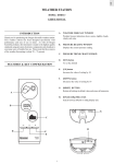
1
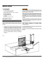
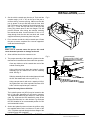
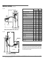
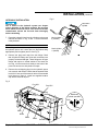
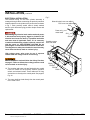
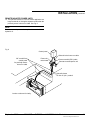
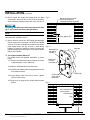
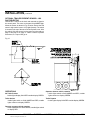
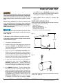
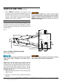
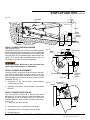
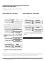
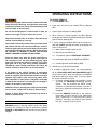
Pit Mounted Vehicle Restraint
SLP3000 and HH3000 Vehicle Restraints
This manual applies to SLP3000 and
HH3000 vehicle restraints manufactured
beginning September 2012 with the serial
numbers 61057072 and higher.
Do not install, operate or service this product unless you
have read and understand the Safety Practices, Warnings,
Installation and Operating Instructions contained in this
User’s Manual. Failure to do so could result in death or
serious injury.
User’s Manual
Installation, Operations,
Maintenance and Parts
Part No. 6011489B
table of contents
Introduction..................................................................2
Safety Signal Words....................................................2
Safety Practices..........................................................3
Installation ..................................................................4
Trailer Presence Sensor (Optional)........................... 12
Start-Up Test..............................................................13
Operating Instructions...............................................17
Planned Maintenance................................................19
Solenoid and Proximity Switch Locations.................. 20
Wiring Diagram..........................................................21
Hydraulic Schematic..................................................24
PLC Diagnostics........................................................25
Troubleshooting.........................................................30
Parts List...................................................................34
Warranty Information.................................................47
Distributor Information...............................................48
introduction
Welcome and thank you for choosing this vehicle restraint.
This User’s Manual contains information that you need to safely install, operate and maintain the vehicle restraint.
It also contains a complete parts list and information about ordering replacement parts. Please keep and read
this User’s Manual before using your new vehicle restraint.
safety signal words
You may find safety signal words such as DANGER, WARNING, CAUTION or NOTICE throughout this User’s
Manual. Their use is explained below:
This is the safety alert symbol. It is used
to alert you to potential personal injury
hazards. Obey all safety messages that
follow this symbol to avoid possible death or injury.
Indicates an imminently hazardous situation which, if
not avoided, will result in death or serious injury.
Indicates a potentially hazardous situation which,
if not avoided may result in minor or moderate
injury.
Indicates a potentially hazardous situation which,
if not avoided, could result in death or serious
injury.
Notice is used to address practices not related to
personal injury.
2
6011489B — SLP3000 and HH3000 Vehicle Restraints
©2012 4Front Engineered Solutions, Inc.
September 2012
safety practices
maintenance and service PRECAUTIONS
Read these safety practices before installing, operating
or servicing the vehicle restraint. Failure to follow these
safety practices could result in death or serious injury.
Before doing maintenance or service be certain that the
power is disconnected and properly tagged or locked out.
Failure to follow these safety practices may result in death
or serious injury.
READ AND FOLLOW THE OPERATING INSTRUCTIONS
IN THIS MANUAL BEFORE OPERATING THE VEHICLE
RESTRAINT. If you do not understand the instructions,
ask your supervisor to teach you how to use the vehicle
restraint.
If the vehicle restraint does not operate properly using the
procedures in this manual, BE CERTAIN TO MANUALLY
CHOCK THE VEHICLE WHEELS BEFORE LOADING OR
UNLOADING. Call your local distributor for service.
Improper installation of vehicle restraint could result in
death or serious injury to dock workers or other users
of the vehicle restraint.
Be certain to follow the installation instructions in this
manual.
INSTALLATION AND OPERATION
Use by untrained people can cause property damage, bodily
injury and/or death. Your supervisor should teach you the
safe and proper way to use the vehicle restraint. Read and
follow the complete operating instructions on page
17 before use. DO NOT USE THE VEHICLE RESTRAINT IF
IT IS NOT WORKING RIGHT. Tell your supervisor it needs
repair.
Do not operate the restraint with equipment, material, or
people directly in front of the restraint.
Place barricades around pit on dock floor and driveway
while installing, maintaining or repairing vehicle restraining
device.
Do not stand in the driveway between the dock and a backing
vehicle.
All electrical troubleshooting and repair must be done by a
qualified technician and meet all applicable codes.
Before doing any electrical work, make certain the power is
disconnected and properly tagged or locked out.
If it is necessary to make troubleshooting checks inside the
control box with power on, USE EXTREME CAUTION. Do
not place fingers or uninsulated tools inside the control box.
Touching wires or other parts inside the control box could
result in electrical shock, serious injury or death.
Keep hands and feet clear of the hook mechanisms at all
times. Stay clear of the restraint when it is moving.
Do not load or unload any vehicle unless you make certain
the vehicle restraint has securely hitched the vehicle’s RIG
(rear impact guard) and set the brakes. If the vehicle restraint
does not hitch the RIG for any reason, BE CERTAIN TO
MANUALLY CHOCK THE VEHICLE WHEELS BEFORE
LOADING OR UNLOADING.
Before chocking vehicle wheels or engaging the vehicle
restraint, dump air from air ride suspensions and set parking
brake.
September 2012
6011489B — SLP3000 and HH3000 Vehicle Restraints
©2012 4Front Engineered Solutions, Inc.
3
installation
tools required
3/8" Allen Wrench
1-1/8" Deep Socket (1/2" Drive)
1/2" x 12" lg. Socket Extension
Torque Wrench (1/2" Drive) - 250 ft lb Capable
3/4" Open End Wrench
7/8" Open End Wrench
15/16" Open End Wrench
Arc Welder
Small Slotted Screwdriver (#0)
preliminary checks
NOTE:
When installing the vehicle restraint with all Kelley® dock
levelers, all Serco® AB dock levelers, and all 6' long Serco®
hydraulic dock levelers the dock leveler must be built for 24"
pit depth.
1. Prepare pit for the vehicle restraint as indicated on the pit
drawings (form 6001890). These drawings will confirm
or establish: unit location and elevation requirements,
control box and light locations, and electrical runs. This
pit planning will be done best with the participation of
all involved parties (contractor, installer, electrician, end
user, etc.). Careful planning is the key to trouble-free
installation.
Before installation read and follow the Safety Practices
on page 3. Failure to follow these safety practices could
result in death or serious injury.
READ AND FOLLOW THE OPERATION INSTRUCTIONS
IN THIS MANUAL BEFORE OPERATING THE VEHICLE
RESTRAINT. If you do not understand the instructions,
ask your supervisor to teach you how to use the vehicle
restraint.
Improper installation of the vehicle restraint could result
in death or serious injury to dock workers or other users
of the vehicle restraint.
Place barricades around pit on dock floor and driveway
while installing, maintaining or repairing vehicle
restraining device.
Be certain bystanders in the driveway stand clear when
vehicle restraint is operated.
Be certain to follow the installation instructions in this
manual.
Fig. 1
4
6011489B — SLP3000 and HH3000 Vehicle Restraints
©2012 4Front Engineered Solutions, Inc.
September 2012
installation, continued
2. Set the vehicle restraint pan into the pit. Tack weld the
crossbar angle (1-1/2" x 40") to the top of the pan to
reinforce during concrete pouring. Make sure that the
pan is square in the pit and flush with the front dock
wall. The bottom front should be flush with grade level.
See Fig. 1. Cover the top and front of the unit with
heavy poly plastic taped to the box flanges. This will
prevent concrete from fouling the restraint mounting
face and anchor bolts. Line drill 6 holes 1/2" dia. x 5.5"
deep through front face into the front dock wall. Install
supplied anchors by hammering them into place.
Fig. 2
Lift here
3. Pour concrete around the vehicle restraint pan. Vibrate
the pour to ensure complete fill to remove trapped air
under and around the pan.
Make sure no concrete enters the pan as this could
cause abnormal operation or damage to the unit.
4. Allow sufficient time for the concrete to set.
5. The proper assembly of the hydraulic cylinders into the
restraint box is essential to ensure trouble free operation.
Fig. 3
3/4" flat washer
Lock nut 3/4-10 UNC, grd 8
(250ft lbs torque required)
Clean any debris out of the restraint box and off the
embed mounting bolts.
Using a hoist and chain lower the hydraulic cylinder
assembly into the restraint box over the mounting
studs. See Fig. 2.
Slide the assembly flush with embed plate and install
the 3/4" flat washer and lock nut (see Fig. 3).
Using a torque wrench, with a min. capacity of 250 ftlbs, tighten each nut ot the required incriments of 50
ft-lbs. until the required torque is reached.
Alignment block
Tighten Mounting Nuts to 250 ft lbs.
The hydraulic power unit (HPU) may be located on the
left or right side depending on the leveler geometry.
The associated tables list the offsets for each leveler
used. Fig. 4A shows the HPU installed for most 4Front
Engineered Solutions, Inc. dock levelers. Fig. 4B shows
the HPU installed in its recommended position for PAL
and mechanical levelers.
6. Anchor the hydraulic power unit onto the pit floor using
the supplied anchor bolts. A minimum of 2 each of the
1/2 x 3-3/4 bolts required through the base flange of the
Hydraulic Power Unit (supplied).
September 2012
6011489B — SLP3000 and HH3000 Vehicle Restraints
©2012 4Front Engineered Solutions, Inc.
5
installation, continued
Fig. 4A
Dock Leveler
"A"
Leveler Size Dimension
Width Length AB
Kelley® aFX, HP, HK
All
6
16 32
Kelley aFX, HP, HK
All
8
16 54
Kelley® aFX
All
10
16 80
Kelley HP, HK
All
10
16 54
Serco® HL, HD, HFC, HLR, HLQ
6
6
22 32
Serco HL, HD, HFC, HLR, HLQ 6.5 & 7
6
25 32
Serco® HL, HD, HFC, HLR, HLQ
8
22 54
Serco HL, HD, HFC, HLR, HLQ 6.5 & 7
8
25 54
Serco® HL, HD, HFC, HLR, HLQ
10
22 54
Serco HL, HD, HFC, HLR, HLQ 6.5 & 7
10
25 54
Kelley® CM, Serco® WL, WS, PAL
6
22 32
Kelley CM, Serco WL, WS, PAL 6.5 & 7
6
25 32
Kelley® CM, Serco® WL, WS, PAL
8
22 54
Kelley CM, Serco WL, WS, PAL 6.5 & 7
8
25 54
Kelley® CM, Serco® WL, WS, PAL
10
22 54
Kelley CM, Serco WL, WS, PAL 6.5 & 7
10
25 54
Serco® AB
6
6
22 32
Serco AB
6.5 & 7
6
25 32
Serco® AB
6
8
22 54
Serco AB
6.5 & 7
8
25 54
Serco® AB
6
10
22 80
Serco AB
6.5 & 7
10
25 80
®
®
®
Hydraulic
power unit
"B"
6
®
Pit floor
®
Front of pit, driveway
KELLEY CM, SERCO WL, WS, PAL
Fig. 4B
6
®
"A"
®
®
®
Pit floor
6
®
®
"B"
6
®
®
Hydraulic
power unit
6
®
NOTE:
6' and 8' Kelley® HK and HP and all Serco® 6' hydraulic dock
levelers use 4" riser kit part number 6001844. Assemblies
using Kelley® aFX with 24" hook pit box may require a split
axle shaft for the pan roller assembly. Reference kit #713-825
and instructions form #5583.
Front of pit, driveway
ALL OTHER LEVELERS
6
6011489B — SLP3000 and HH3000 Vehicle Restraints
©2012 4Front Engineered Solutions, Inc.
September 2012
installation, continued
HYDRAULIC INSTALLATION
Fig. 6
Hold down
cylinder
Dirt or debris in the hydraulic system can hamper
proper operation of the vehicle restraint. Do not allow
dirt or debris to enter the hoses. If the hoses do become
contaminated, remove the line and clean thoroughly
before reinstalling.
7. Route the hydraulic lines from the cylinders to the pump
manifold as shown in Fig. 6 and 7. Hoses should be
neatly dressed.
NOTE:
Elbow fitting on the hold down cylinder must point towards
the hydraulic power unit. Loosen jam nut, align elbow fitting
appropriately and re-tighten jam nut. See Fig. 5.
Reservoir
fill port
Hook cylinder
2 (restract)
Hook cylinder
1 (extend)
8. Remove the plugs and caps from the fittings Check
that all hydraulic fittings are clean and connections are
properly connected and tight. These fittings are JIC type
fittings and require no thread sealant. If the hoses are
too long, coil the excess hose neatly at the base of the
power unit and secure with plastic tie straps.
9. Remove the red shipping plug from the hydraulic power
unit reservoir and discard. Check that the hydraulic fluid
level is full. If not, top off the reservoir to the recommended
level shown on page 13. Install the supplied breather
cap into the reservoir fill port.
Fig. 5
Port HC1
Port HC2
Hook
Cylinder
Hold down
cylinder port HDC
10:00
Hold
down
cylinder
60°
2:00
Jam nut
PRS 1
PRS 4
PRS 3
September 2012
PRS 2
Port HDC
6011489B — SLP3000 and HH3000 Vehicle Restraints
©2012 4Front Engineered Solutions, Inc.
7
installation, continued
Electrical INSTALLATION
The electrical wiring for the hook cylinder assembly is
managed through cables connecting the proximity switches
located under the hook cylinder to the junction box as shown
in Fig. 7. Each proximity switch cable is clearly marked
and the quick disconnect plug provides simple access and
replacement.
Before doing any electrical work, make certain the power
is disconnected and properly tagged or locked off. All
electrical work must be done by a qualified technician
and must meet all applicable codes. If it is necessary
to make troubleshooting checks inside the control box
with the power on, USE EXTREME CAUTION. Do not
place fingers or uninsulated tools inside the control box.
Touching wires or other parts inside the control box may
cause electrical shock, death or serious injury.
Fig. 7
Solenoid valve home run cable
PS1 home run cable
SV3
Power unit
motor leads
SV1
SV2
Proximity sensor
home run cable
High voltage power wires must be run in separate
conduit from low voltage control circuit wiring.
Before installation read and follow the Safety Practices
on page 3. Failure to follow these safety practices could
result in death or serious injury.
10. The restraint and power unit are fitted with color coded
home run cables for the proximity sensors, pressure
switch, and solenoid valves. These cables are 30' long
and can be run directly to the control panel. See page 23
Fig. 24.
PRS1
PRS4
PRS3
PRS2
11. The motor shall be wired directly from the control panel
to the motor J-box.
8
6011489B — SLP3000 and HH3000 Vehicle Restraints
©2012 4Front Engineered Solutions, Inc.
September 2012
installation, continued
Remote mounted power units
12. The hydraulic hoses for a remote mount application are
longer and shall run through a separate conduit than the
proximity sensor’s home run cable. See Fig. 8.
NOTE:
Remote mounted power units require 44 oz. of additional
hydraulic oil.
Fig. 8
Control panel
Solenoid valve home run cable
3/4" conduit from
control panel
for proximity sensor
home run cable
Power unit
motor leads
Pressure switch (PS1) cable
Remote mounted power unit
Hydraulic hoses
run thru 4" (min.) conduit
Leveler not shown for clarity.
September 2012
6011489B — SLP3000 and HH3000 Vehicle Restraints
©2012 4Front Engineered Solutions, Inc.
9
installation, continued
16. Mount control box inside the building with the lights
centered 60" above the floor, to the left of the doorway.
Allow sufficient clearance to dock door track. See Fig. 9.
Fig. 9
Mount control box on left
side of door opening.
mounting hardware by others.
Connecting 24V lights to the 120V control panel terminals
10, 11, OL1 or OL2 will destroy the light fixture.
NOTE:
For 120V exterior lights, use wiring kit 6003336. Installation
instructions are included in the kit.
17. Mount and wire outside 24V LED signal light assembly
into the control box to terminals 7 for RED, 8 for GREEN
and 9 for common. Terminals are located on the control
panel output board. See Fig. 10 and 11. (See Wiring
Diagram on page 23.) Make sure when mounting the
light assembly that the Red light is on top and the Green
light is on the bottom.
18.The Optional Audible Alarm Kit
For Audible Alarm Kit 6003335 installation in control
panel.
18.1Remove knockout from bottom of panel. (knockout
is approximately 1-1/8" in diameter).
Eye level, approx. 60"
Fig. 10
Red light
Red lead from
red light to
terminal 7
Black lead
common
to terminal 9
18.2Remove threaded collar from alarm face.
18.3Feed face of Audible Alarm through hole (knockout)
from inside the panel.
18.5Plug the 2 pin plug into the Output board's Alarm
Socket.
Green light
Green lead from
green light to
terminal 8
18.4Screw plastic collar over face of alarm. Tighten
collar to secure alarm.
Fig. 11
Allow clearance for
seal or shelter
External light
Sign
Approx. 90"
10 6011489B — SLP3000 and HH3000 Vehicle Restraints
©2012 4Front Engineered Solutions, Inc.
September 2012
installation, continued
19. The Leveler Stored Sensor
For leveler stored sensor installation/termination to
control panel.
19.1To enable the leveler stored sensor feature flip
the input board dip switch position “3” to the OFF
position. Input 10 LED on the PLC will go out.
19.2The sensor 625-203 is a 4 wire device. First
terminate the Positive lead (brown wire) to any “C”
terminal on the input board.
19.3Terminate the Negative lead (blue wire) to any “OV”
terminal on the input board.
19.4Terminate the Load or Switched lead (black wire) to
the “19” terminal on the input board.
19.5Tape (insulate) the unused white wire.
22. Permanently mount the vehicle driver’s instruction sign
on the outside wall under the signal light. Allow sufficient
clearance for dock seals/shelters. See Fig. 11.
23. Wire motor to control box. See Wiring Diagram on page 21.
24. Wire solenoids on manifold to control box. Plug electrical
cords from junction box into the appropriate solenoid
coils. See Wiring Diagram on pages 23.
25. Connect proximity switch cables from junction box to
the appropriate terminals in the control box. See Wiring
Diagram on pages 23.
26. After wiring motor, solenoids and proximity switches,
neatly tie-wrap electrical cords together that go to
junction box.
20. The leveler interlock (optional)
For installation of leveler interlock/termination to control
panel:
20.1Identify interlock control circuit wiring from dock
leveler (1 pair of wires).
NOTE:
A fused disconnect is required for each vehicle restraint as a
means of disconnecting and limiting incoming power to the
control box. This disconnect is supplied by others. For correct
dual element time delay motor rated fuse size refer to wiring
diagram on page 21.
20.2Terminate these 2 wires from the leveler to terminals
13 and 14 on the output board connector terminals
in the control panel.
27. Check that the fused disconnect for this installation is
a lockable type and meets all applicable electrical and
safety codes.
NOTE:
Termination is not polarity sensitive allowing installation to
either terminal with either wire. This interlock circuit is fused
at 2 amps.
28. Mount the fused disconnect near the control box and
wire power to it from an available power source.
21. The Vehicle Presence Sensor (Optional)
For vehicle presence sensor installed terminaton see
schematic on page 23.
21.1The sensor is a 4 wire device. First terminate the
positive lead (brown wire) to any "C" terminal on
the input board.
29. Run power wires from the fused disconnect to the control
box.
30. The vehicle restraint is now ready for start-up and test.
Be sure to securely close the control box enclosure at
this time.
21.2Terminate the negative lead (blue wire) to any "0V"
terminal on the input board in the panel.
21.3Terminate the load lead (black wire) to the "17"
terminal on the input board in the panel.
21.4Tape (insulate) the unused white wire.
September 2012
6011489B — SLP3000 and HH3000 Vehicle Restraints
©2012 4Front Engineered Solutions, Inc.
11
installation, continued
Optional Trailer Present sensor – LS8
photoelectric
LS8 senses a vehicle at the dock and transmits a signal to
the control panel. This turns on the panel face AMBER light.
Mount the sensor as shown in Fig. 12 below. Ensure the LS8
sensor's logic switch is set to L/O (Light Operate). The switch
is located on the top of the sensor under a plastic cover. Wire
the switch. Wire the sensor into the panel per schematic on
page 23 and step 21 on page 11. When a vehicle is present
at the door, PLC Input 8 will go on.
Fig. 12
OPERATIONS
Operator releases vehicle restraint
• Inside lights switch to Solid AMBER and RED, outside
lights continue to display GREEN.
Trailer Arrives
• Inside lights switch to Solid AMBER and RED, outside
lights continue to display GREEN.
Trailer Departs
• Inside lights display Solid RED outside display GREEN.
No Trailer Present
• Inside lights display Solid RED outside display GREEN.
Operator engages vehicle restraint
• Inside lights switch to Solid GREEN, outside lights switch
to display RED.
12 6011489B — SLP3000 and HH3000 Vehicle Restraints
©2012 4Front Engineered Solutions, Inc.
September 2012
start-up and test
Do not service this product unless you have read and
followed the Safety Practices, Warnings, and Operation
instructions contained in this manual. Failure to follow
these safety practices could result in death or serious
injury.
Before doing maintenance or service, remove power
at the fused disconnect. Disconnect must be properly
tagged or locked out during maintenance or service of
equipment. Failure to disconnect power may result in
death or serious injury.
Before putting the vehicle restraint into service, there
are preparations and functional checks that must be
made. They are:
and green. Push the RELEASE pushbutton to reset
the lights. The inside light will switch to red and the
outside lights will switch to flashing green.
6. Check hydraulic fluid in reservoir. If required, add
hydraulic oil.
Acceptable Hydraulic Oils
A petroleum based, all weather hydraulic fluid with a viscosity
of 15 CST @ 40°C (100°F), such as:
Shell Tellus T 15
Mobil Aero HFA (49011)
Exxon Univis: HV13, N15, J13
Texaco Aircraft Oil #1554
U.S. Oil Co., Inc #ZFI-5606 (low temp.)
Fig. 13
1) Bleeding air from the hydraulic cylinders and lines.
2) Checking operating range of vehicle restraint without
vehicle backed into dock.
34-1/2"
1. Turn power on at fused disconnect.
2. Activate service mode by simultaneously pressing and
holding the ENGAGE and RELEASE pushbuttons for
5 seconds. Release both pushbuttons as soon as both
panel lamps extinguish.
3. Rotate and release the RESTRAINT OVERRIDE switch.
Observe PLC input status light #1. If motor rotation is
correct, the hold down cylinder should immediately drive
the hook cylinder downward, turning on PRS1. If the
motor runs and no motion occurs, interchange motor
power wires T1 and T2 (three phase motors only).
8"
Fig. 14
4. To clear service mode and return to normal operation,
simultaneously press and hold the ENGAGE and
RELEASE pushbuttons for 2 seconds, Alternatively,
service mode will exit if no pushbuttons are pressed for
60 seconds. See page 25 for details of service mode.
5. Push ENGAGE pushbutton. The hook should lower,
fully extend, fully raise, and partially retract. Finding no
vehicle, the hook will extend, fully lower, fully retract into
the pit and the alarm (if equipped) will sound. The motor
should shut off. The inside lights should change to red
and amber flashing. Rotate the selector switch to the
RESTRAINT OVERRIDE position to silence the alarm
(if equipped). The inside lights will change to amber
September 2012
* Use service mode to jog hook into position before checking
oil level. (Ref. page 25)
6011489B — SLP3000 and HH3000 Vehicle Restraints
©2012 4Front Engineered Solutions, Inc.
13
start-up and test, continued
7. Press ENGAGE pushbutton and measure lower
and upper limits of the vertical operating range. The
operating range should be 8" and 34.5" respectively.
See Fig. 13. It is important to verify that the PRS1 signal
remains on (PLC input 1) when the hook is lowered,
especially as the hook is retracting.
Before doing maintenance or service remove power
at the fused disconnect. Disconnect must be properly
tagged or locked out during maintenance or service of
equipment. Failure to disconnect power may result in
death or serious injury.
NOTE:
The upper and lower limits of the operating range given in
manual are for the dock height and pit depth indicated on the
pit drawing. These limits may not be attainable if variations
in dock height and/or pit depth exist. Consult factory if this
situation occurs.
Fig. 15
14.55
30.50
(±0.375)
30.00
8.62
Inside pit box
6.00
7.37
RIG
(rear
impact
guard)
Grade level
15.82
HOOK CYLINDER OPERATING RANGE
(Without Optional Cover)
Adjustment of the pressure relief above the maximum
range could result in damage to the power unit or
cylinders.
Hook raises rapidly. Stand clear to the side of the hook
when making measurements or adjustments.
Adjustment of the hook cylinder can be achieved through
various means. The full working range is noted in Fig. 13.
Proximity Switch 1 controls the lower travel limit of the hook.
The Proximity Switch (PRS1) should be factory set at 3/32"
away from the sensor block and ready for service. Use the
following instructions to fine tune the hook position to fit your
installation. See Fig. 17.
1. Adjustment of the sensor block counterclockwise (CCW)
lowers the hook.
2. Adjusting of the sensor block clockwise (CW) Raises
the hook.
14 6011489B — SLP3000 and HH3000 Vehicle Restraints
©2012 4Front Engineered Solutions, Inc.
September 2012
start-up and test, continued
Fig. 16
Cover plate
24.39
8.62
6.00
7.37
RIG
(rear
impact
guard)
Grade level
15.82
HOOK CYLINDER OPERATING RANGE
(With Optional Cover)
For applications requiring a pit cover the hook cylinder height will
need to be adjusted to prevent hitting the cover. For shallow pits
26" and lower the cyclinder stop bolt will need to be replaced with
the longer option. The hook assembly ships with a stock bolt 5/818UNF x 1-1/2. that can adjust hook height between 30-32". Use
5/8-18UNF x 1-3/4 bolt for 24-30" hook height range.
Fig. 17
Sensor
block
Adjustment
Hook raises rapidly. Stand clear to the side of the hook
when making measurements or adjustments.
HOOK CYLINDER ADJUSTMENTS
Proximity Switch 1 controls the lower travel limit of the hook.
The Proximity Switch (PRS1) should be factory set at 3/32"
away from the sensor block and ready for service. Use the
following instructions to fine tune the hook position to fit your
installation. See Fig. 17.
1. Adjustment of the sensor block counterclockwise
(CCW) lowers the hook.
3/8" Allen socket
3/32" gap
Fig. 18
Jam nut
Proximity
switch
(PRS1)
Adjusting bolt
(optional)
2. Adjusting of the sensor block clockwise (CW) Raises
the hook.
HOOK CYLINDER UPPER TRAVEL
The hook cylinder is fitted with a stop bolt that allows
adjustment of the hook maximum height depending upon
the application or with cover plates. See Fig. 16. The bolt is
located between the upper cylinder trunnion mount blocks.
See Fig. 18.
1. Loosen the jam nut on the bolt .
2. Adjusting the bolt in, increases the hook height.
3. Adjusting the bolt out, decreases the hook height.
4. Retighten jam nut.
September 2012
6011489B — SLP3000 and HH3000 Vehicle Restraints
©2012 4Front Engineered Solutions, Inc.
15
start-up and test, continued
The following testing sequence are recommended for the
initial check out of the Restraint operation. The cylinder and
line should be purged and free of air.
HOOK CYLINDER TEST — NO VEHICLE
1. Apply power to the control panel.
2. With the restraint in stored position (UP).
3. Check the panel lights and exterior lights.
Control Panel Lights
R
A
G
Exterior Lights
RED ONLY
R
G
GREEN FLASHING
4. Push the ENGAGE button on the panel. The restraint
will cycle through its motion. Lower-extend-raise and
retract, finding no vehicle. The restraint will return to
stored position and the alarm will sound (if equipped).
The motor will shut off and the lights will show:
Control Panel Lights
R
A
G
Exterior Lights
RED & AMBER FLASHING
R
G
RED FLASHING
5. Rotate the selector switch to the RESTRAINT
OVERRIDE to silence the alarm (if equipped). The lights
will show:
Control Panel Lights
R
A
G
Exterior Lights
GREEN & AMBER
R
G
HOOK CYLINDER TEST — WITH VEHICLE
1. Position the vehicle with a RIG (rear impact guard) at
dock.
2. Push ENGAGE. The restraint will cycle through its
motion and latch the RIG. The motor should shut off
and lights will show:
Control Panel Lights
Exterior Lights
R
A
G
GREEN ONLY
R
G
RED FLASHING
3. Push the RELEASE button and the restraint should
return to stored position in the pit. The lights will show:
Control Panel Lights
Exterior Lights
R
A
G
RED ONLY
R
G
GREEN FLASHING
4. If the restraint or lights do not operate as stated above
steps, refer to the troubleshooting guide starting on
page 30.
NOTE:
If 120V lights are used, they will not flash.
RED FLASHING
6. Push the RELEASE button to reset the lights to:
Control Panel Lights
Exterior Lights
R
A
G
RED ONLY
R
G
GREEN FLASHING
7. If the restraint or lights do not operate as stated above
steps, refer to the troubleshooting guide starting on
page 30.
Dock leveler can now be installed in pit per dock leveler’s installation instructions. When placing dock leveler in pit, make
sure all components of the vehicle restraint including hydraulic hoses and electrical cords do not interfere with dock leveler.
If any welding is done in the pit, make sure to cover all components of vehicle restraint and disconnect power.
16 6011489B — SLP3000 and HH3000 Vehicle Restraints
©2012 4Front Engineered Solutions, Inc.
September 2012
operating instructions
to chock vehicle:
Before operating the vehicle restraint, read and follow the
Safety Practices, Warnings, and Operation instructions
contained in this manual. Use by untrained people could
result in death or serious injury.
Do not use the Restraint if it looks broken or does not
seem to work right. Tell your supervisor at once.
Keep hands and feet clear at all times. Stay clear of the
vehicle restraint when it is moving.
Do not load or unload any vehicle unless you make certain
the vehicle restraint has securely hitched the vehicle’s
RIG (rear impact guard) and set the brakes. If the vehicle
restraint does not hitch the vehicle’s RIG for any reason,
BE CERTAIN TO MANUALLY CHOCK THE VEHICLE
WHEELS BEFORE LOADING OR UNLOADING.
Enter the vehicle only when the green signal light on
the control box is on. You must check the green signal
light each time that the vehicle is entered. If the green
light goes off at any time during loading operations,
immediately cease loading operations and check the
vehicle restraint to insure that it is securely hitched.
If the power to the vehicle restraint is interrupted,
immediately cease operations and check the unit. When
power is reapplied, the restraint will usually not require
operator input unless hook was moving when power
was interrupted. If, when power is reapplied, inside light
is flashing red and hook is not moving press engage or
release as desired to reset restraint.
Vehicles leaving or moving when loading and unloading
are in process, could result in death or serious injury.
Failure to follow these safety practices may result in
death or serious injury.
NOTE:
To stop the restraint, simultaneously press the ENGAGE and
RELEASE buttons to halt the restraint at any time during
its travel. The restraint can then be restarted by pressing
ENGAGE or RELEASE and will resume from the position it
stopped.
September 2012
1. Press ENGAGE button.
2. Inside light will switch from steady Red to flashing
Red.
3. Outside lights will switch to flashing Red.
4. When vehicle is properly hitched, the Red flashing
inside light will switch to a Green steady light. Outside
light will remain flashing Red.
5. If vehicle cannot be hitched, Red light will continue to
flash with Amber light and fault alarm (if equipped) will
sound. If this occurs:
5.1 Make certain vehicle brakes are set.
5.2 Manually chock vehicle tires.
5.3 Turn selector switch to RESTRAINT OVERRIDE.
5.4 Inside lights will switch to Amber and Green .
5.5 Outside lights will remain flashing Red.
6. Vehicle may now be loaded/unloaded.
7. If a restraint malfunction occurs, the visual indication
will be a SOLID RED AND FLASHING AMBER LIGHT
on the control panel. When this happens, the Amber
light will be flashing a trouble code. This may happen
for various reasons that require:
7.1 To return restraint to the home position, Press
and hold the RELEASE pushbutton selector
switch.- This will activate the ARTH mode.
Continue to hold until the restraint is stored. If
the fault is cleared, the restraint can now be reengaged.
7.2 Press the ENGAGE pushbutton. If the cause of
failure has not been cleared it may malfunction
again. Repeat step 7.1 to return the hook to home
position if necessary. Use manual wheel chocks
until unit is repaired. Call for service.
6011489B — SLP3000 and HH3000 Vehicle Restraints
©2012 4Front Engineered Solutions, Inc.
17
operating instructions, continued
to Release vehicle:
1. Store dock leveler. (If present remove manual wheel
chocks.)
2. Press RELEASE pushbutton.
3. Inside lights will switch to flashing red.
4. Outside lights will continue to flash red.
5. After hook is stored, inside lights switch to steady red.
Outside light will switch to flashing green.
NOTE:
To stop the restraint, simultaneously press the ENGAGE and
RELEASE buttons to halt the restraint at any time during
its travel. The restraint can then be restarted by pressing
ENGAGE or RELEASE and will resume from the position it
stopped.
NOTE:
If 120V lights are used, they will not flash.
6. Vehicle may now pull out.
RESTRAINT OVERRIDE MODE (Lights Only)
In some instances it is desirable to put the restraint into
RESTRAINT OVERRIDE mode without extending the hook
out of the pan. An example would be if a lift gate vehicle is
positioned at the dock.
to chock vehicle :
1. Make certain vehicle brakes are set.
2. Manually chock vehicle tires.
3. Turn selector switch to RESTRAINT OVERRIDE.
4. Inside lights will switch from steady Red to Amber and
Green. Outside lights will switch from flashing Green
to flashing Red.
5. Vehicle may now be loaded/unloaded.
to release vehicle
(when in restraint override):
1. Store dock leveler. If present, remove manually placed
chock.
2. Press Release button.
3. Inside light will switch to Red.
4. Outside light will flash GREEN.
5. Vehicle may now pull out.
18 6011489B — SLP3000 and HH3000 Vehicle Restraints
©2012 4Front Engineered Solutions, Inc.
September 2012
PLANNED maintenance
Fig. 19
Before doing any electrical work (including changing
bulbs), make certain the power is disconnected and
properly tagged or locked off.
Do not service this product unless you have read and
followed the Safety Practices, Warnings, and Operation
instructions contained in this manual. Failure to follow
these safety practices could result in death or serious
injury.
Grease
trunnions
After checking lights, be certain lights are returned to
the proper display. If no vehicle is at the dock, or the
vehicle is not chocked, the red inside light should be lit
and green outside light should be flashing. If a vehicle
is at the dock and RIG (rear impact guard) is hitched, the
green inside light should be lit and the red outside light
should be flashing.
Daily
quarterly
1. Operate the vehicle restraint to assure that it operates
smoothly.
1. Grease hook and hold down cylinder trunnions. Remove
trunnion caps and spray with a liberal amount of white
lithium grease. See Fig. 19.
2. Check all lights and optional fault alarm (if equipped) to
ensure they are in proper working order.
3. Inspect dock bumpers. Worn, torn, or missing bumpers
must be replaced.
MONTHLY
1.Check fluid level on the reservoir. If required add hydraulic
oil. See Fig. 14.
2.Check all operating, warning, and caution labels and signs
to be sure they can be read. Replace them if required.
2. Check all operating, warning, and caution labels and
signs to be sure they can be read. Replace them if
required.
3. Inspect dock bumpers. Worn, torn, or missing bumpers
must be replaced.
as required
1. Clean debris out of pan in pit.
3.Check for loose, frayed and damaged wires or hydraulic
leaks.
September 2012
6011489B — SLP3000 and HH3000 Vehicle Restraints
©2012 4Front Engineered Solutions, Inc.
19
solenoid and proximity switch locations
SOLENOID 1: Lowers hook when energized.
Fig. 20
SOLENOID 2: Extends hook when energized.
Port HDC
SOLENOID 3: Extends hook when energized.
SV3
Port HC2
SV2
PRS1: On when hook is fully lowered.
PRS2: On when hook is not fully extended.
Port HC1
SV3
Port HDC
PRS3: On when hook is not in working range (when hook
does not hitch a rear impact guard).
PRS4: On when hook is fully retracted.
SV1
Pressure
switch (PS1)
Fig. 21
Port HC1
Port HC2
PRS 1
PRS 4
PRS 3
PRS 2
Note: Orientation of prox leads. PRS 1-PRS 4
20 Port HDC
6011489B — SLP3000 and HH3000 Vehicle Restraints
©2012 4Front Engineered Solutions, Inc.
September 2012
wiring diagram
Fig. 22
Before doing any electrical work, make certain
the power is disconnected and properly tagged or
locked off. All electrical work must be done by a
qualified technician and meet all applicable codes.
If it is necessary to make troubleshooting checks
inside the control box with the power on, USE
EXTREME CAUTION. Do not place your fingers or
uninsulated tools inside the control box. Touching
wires or other parts inside the control box could
result in electrical shock, death or serious injury.
Use caution when wiring outside lights. Be sure
of the voltage rating of the light assembly you are
installing.
Damage to outside lights caused by improper hookup over voltage is NOT covered by warranty.
VOLTAGE
120
208
240
BCPD
25A
15A
12.5A
SINGLE PHASE PANEL REFERENCE
FUSE F2 MOTOR FLA
PANEL FLA
4A
14A
17.67A
2.5A
7A
10.56A
2A
6A
8.83A
SERCO P/N
6003330V1
6003330V2
6003330V3
KELLEY P/N
6003331V1
6003331V2
6003331V3
SERCO P/N
6003330V4
6003330V5
6003330V6
6003330V7
6003330V8
KELLEY P/N
6003331V4
6003331V5
6003331V6
6003331V7
6003331V8
USE CLASS CC TIME DELAY FUSES
VOLTAGE
208
240
380
480
575
BCPD
8A
7A
4A
4A
3A
THREE PHASE PANEL REFERENCE
FUSE F2 MOTOR FLA
PANEL FLA
2.5A
4A
5.75A
2A
3.6A
5.03A
1A
2A
2.52A
1A
1.8A
2.52A
0.8A
1.5A
2.25A
USE CLASS CC TIME DELAY FUSES
September 2012
6011489B — SLP3000 and HH3000 Vehicle Restraints
©2012 4Front Engineered Solutions, Inc.
21
wiring diagram, continued
Fig. 23
Switch, N.O.
when hook fully extended
ON when hook fully retracted
Engage
Release
Optional door Closed
Optional Leveler Stored
22 6011489B — SLP3000 and HH3000 Vehicle Restraints
©2012 4Front Engineered Solutions, Inc.
September 2012
wiring diagram, continued
Fig. 24
September 2012
6011489B — SLP3000 and HH3000 Vehicle Restraints
©2012 4Front Engineered Solutions, Inc.
23
hydraulic schematic
Fig. 25
PS1 factory set
@ 250 PSI
Hold down
cylinder
Hook cylinder
HC1
HC2
HDC
SV3
Valve
block
2
SV2
1
1
2
1
2
CV2
5 PSI
SV1
3
2
1
2
1
CV1
5 PSI
P1
R1
Hydraulic pump primary relief pressure set at 600 PSI.
24 6011489B — SLP3000 and HH3000 Vehicle Restraints
©2012 4Front Engineered Solutions, Inc.
September 2012
plc diagnostics
Service
All electrical troubleshooting and repair must be done by
a qualified technician and meet all applicable codes. The
diagnostic and service modes are meant for installation
and troubleshooting only.
Do not service this product unless you have read and
followed the Safety Practices, Warnings, and Operating
Instructions in this manual. Failure to follow these safety
practices could result in death or serious injury.
Keep hands and feet away from the restraint when in
Diagnostics Mode. Operation may return as soon as
the fault is cleared. Failure to keep clear could result in
death or serious injury.
This mode provides full manual control and a means to
drive the restraint for a user determined amount of time in all
supported directions. This mode is not subject to sequencing,
proximity switch status or timeouts.
To activate Service mode: simultaneously press and hold
Engage and Release pushbuttons for 5 seconds. All
panel lamps will extinguish.
To clear Service mode and return to normal operation:
simultaneously press and hold Engage and Release
pushbuttons for 2 seconds. Panel lamps will resume the
state held before Service mode activation or assume a
new condition based on new input variables. Unit will
exit Service mode automatically if no panel buttons are
pressed in a 60 second time interval.
Diagnostics
This mode will be entered when a restraint malfunction
occurs which is defined as a movement error or proximity
switch failure. Dynamic monitoring will trap movement and
intermittent restraint failures. The amber lamp will serve
to report these failures by flashing a trouble code. Trouble
code definitions are referenced in this manual on page 27.
Automatic Return to Home (ARTH)
This feature will return the restraint to its home position in
the event of restraint malfunction. This mode can only be
entered when a restraint malfunction has occurred. This
will be the preferred recovery mode for the standard user
because it does not require the user to visually monitor the
restraint while operating. To initiate this mode, Press and
hold the RELEASE pushbutton switch and continue to hold
until the restraint is stored. Upon commencement, the unit
will automatically begin a predetermined sequence and
reset when it has reached the home position. The sequence
can be terminated at any time by releasing the release
pushbutton switch and can be reactivated as long as
the restraint malfunction exists. This mode of operation does
not acknowledge proximity switches or run timeouts. It runs
along a predetermined path for a predetermined time to
allow for proper storage of the restraint following a restraint
malfunction.
September 2012
When restraint leaves service mode it may move or raise
rapidly. Stay clear of hook at all times.
While Service mode is active, press and hold the Engage
pushbutton to extend the hook. Likewise press and hold
the Release pushbutton to retract the hook. Rotate the
RESTRAINT OVERRIDE switch to drive the hook down,
then release and rotate again to release the hook. Each time
the RESTRAINT OVERRIDE switch is sequenced the unit
will switch between driving the hook down and releasing it
to the raised position. These commands can be issued in
any order and will maintain the ordered drive motion for as
long as the switches are held active. This implementation is
intended to smooth installation efforts.
6011489B — SLP3000 and HH3000 Vehicle Restraints
©2012 4Front Engineered Solutions, Inc.
25
plc diagnostics, continued
PositionInside Light Flash Rate
Home
Red
N/A
Moving
Red (flashing)
Medium
Stopped
Red (flashing)
Slow
Hitched
Green N/A
RESTRAINT OVERRIDE
Green and Amber
N/A
Trailer Not Found
Red (flashing), Amber (flashing) and horn (pulsing)
Slow
Restraint Malfunction
Red (on) and Amber (flashing)
Code
and ARTH mode
Service Mode
None
N/A
Outside light flashes green only when all conditions are safe for the vehicle to arrive or depart, i.e. restraint and dock
leveler stored with no alarms present. It flashes red by default.
26 6011489B — SLP3000 and HH3000 Vehicle Restraints
©2012 4Front Engineered Solutions, Inc.
September 2012
plc diagnostics, continued
Diagnostics
If a restraint malfunction has occurred:
● Inside Amber lamp is flashing a trouble code.
● Engage and Release functions are disabled.
● Inside Red lamp is on.
To identify the specific problem, count the flashes of the
Amber lamp and compare the number to the table below.
The count sequence will be repeated until the restraint
malfunction is cleared. A two second pause between flash
sequences is employed.
A single, slow repeated, red flash is not an error. The restraint
power has been stopped either by using intervention or
power loss. Press Engage or Release to continue.
Trouble CodeTrouble Definition
2
Lower/Raise timeout:
Failure to detect PRS1 on while fully lowered or off when raised.
3
Extend timeout:
Failure to detect PRS2 off while fully extended
4
Retract to RIG timeout:
Failure to dectect PS1 or PRS3 on while seeking ICC
5
Full retract timeout:
Failure to detect PRS4 on while retracting to home position
6
Reaction timeout:
Slow cylinder response or proximity switch failure (PRS2/3/4)
7
Hook is not stored or at least one of the following proximity switches has failed (PRS2/3/4)
8
PS1 failure
9
PS1 on while retracting to home position or fully retracted while PRS4 is off
(possible obstruction present)
Static proximity switch failure (PRS2/3/4)
10
11
September 2012
Master motor run timeout:
Motor has exceeded its maximum allowed run time
6011489B — SLP3000 and HH3000 Vehicle Restraints
©2012 4Front Engineered Solutions, Inc.
27
plc diagnostics, continued
Control Panel — LED Display
The vehicle restraint is controlled by a solid state
Programmable Logic Controller (PLC) which reads input
signals from the pushbuttons and proximity sensors, and
closes the appropriate output relays to the motor and to the
warning lights.
Input Signals
0 - Engage pressure switch (On when pressure indicated), PS1
1 - Lowered proximity switch (On when fully lowered), PRS1
2 - Extended proximity switch (Off when fully extended), PRS2
3 - Working range proximity switch (Off when in working range), PRS3
4 - Retracted proximity switch (On when fully retracted), PRS4
5 - Restraint Override (momentarily off when selected)
6 - Engage pushbutton
7 - Release pushbutton
8 - Optional Trailer Presence Sensor* (DIP switch position 4)
9 - Optional Door Closed switch (DIP switch position 2)
10 - Optional Leveler stored switch (DIP switch position 3)
11 - Spare Input
12 - Spare Input
13 - Spare Input
Output Signals
0 - Inside Red light
1 - Inside Amber light
2 - Inside Green light
3 - Outside light relay (red when off)
4 - Solenoid valve 1 (Lowers hook when on)
5 - Solenoid valve 2 (Extends or lowers hook when on)
6 - Solenoid valve 3 (Extends or raises hook when on)
7 - Motor
8 - Audible Alarm (Optional)
9 - Leveler Interlock
*Restraint Panels Only. Master panels may be in a different
location.
0
1
2
3
4
5
6
7
8
9 10 11 12 13
INPUTS
STAT
ERR
RUN
PWR
OUTPUTS
0
1
2
3
4
5
6
7
8
9
TWIDO PLC DISPLAY
28 6011489B — SLP3000 and HH3000 Vehicle Restraints
©2012 4Front Engineered Solutions, Inc.
September 2012
plc diagnostics, continued
The chart below shows all of the valid conditions for the PLC unit in normal operation.
6
7
8
9 10 11 12 13
1
STAT
RUN
0
ERR
PWR
INPUTS
F
0
2
3
4
OUTPUTS
1
2
3
4
5
6
7
8
5
6
7
8
9 10 11 12 13
9
INPUTS
PWR
RUN
ERR
STAT
E E E
F
0
0
1
2
3
4
OUTPUTS
6
7
8
1
2
3
4
5
5
6
7
8
9 10 11 12 13
2
3
4
1
2
3
4
5
7
8
5
6
7
8
9 10 11 12 13
9
INPUTS
OUTPUTS
1
2
3
4
5
6
7
8
Restraint Override
selected
9
6
7
8
9 10 11 12 13
5
4
6
7
8
9 10 11 12 13
1
2
3
5
OUTPUTS
6
7
8
9
INPUTS
E
OUTPUTS
F
0
1
0
2
3
4
1
2
3
4
5
6
7
8
9
5
6
7
8
9 10 11 12 13
INPUTS
E E E
F
0 1
0
1
2
3
4
5
OUTPUTS
2
3
4
5
6
7
8
9
6
7
8
9 10 11 12 13
2
3
4
5
6
7
8
9 10 11 12 13
INPUTS
0
F F
0 1
1
2
3
4
5
6
7
OUTPUTS
F
8 9
INPUTS
E E E E
OUTPUTS
PWR
STAT
E
F
0
Unsucessful hitch
(TNF)
0
PWR
STAT
1
ERR
0
OUTPUTS
6
Step 8
Hook retracting
9
INPUTS
F
0
Step 7
Hook lowering
4
ERR
5
3
STAT
4
2
STAT
9
STAT
8
STAT
7
5
INPUTS
STAT
6
F
0 1
RUN
5
4
ERR
4
3
ERR
3
2
E
ERR
ERR
STAT
3
2
1
ERR
RUN
2
1
0
PWR
PWR
1
0
Step 6
Hook extending
(releasing)
RUN
9 10 11 12 13
PWR
8
RUN
7
PWR
6
RUN
5
RUN
4
0
ERR
Step 4
Hook engaging
(Seeking RIG)
3
OUTPUTS
RUN
Step 3
Hook raising
2
INPUTS
PWR
Step 2
Hook extending
1
RUN
Step 1
Hook lowering
0
PWR
Home
Hook fully retracted
(stored)
0
1
2
3
4
5
6
7
8
9
On
September 2012
0
1
2
3
4
5
6
7
8
INPUTS
STAT
ERR
RUN
OUTPUTS
0
1
2
3
4
F
Flashing
E
LED on or off (either condition may be
present during sequence)
9 10 11 12 13
E
PWR
Step 5
Hook fully engaged
(RIG contacted)
5
6
7
8
9
6011489B — SLP3000 and HH3000 Vehicle Restraints
©2012 4Front Engineered Solutions, Inc.
29
troubleshooting
Use the Troubleshooting Guide if the vehicle restraint fails
to perform properly. Find the condition that most closely
matches your situation, and make the recommended
adjustments.
Before doing maintenance or service remove power
at the fused disconnect. Disconnect must be properly
locked out during maintenance or service of equipment.
Failure to disconnect power may result in death or
serious injury.
Some of the following steps will be taken with the power
on and the control box open. Only qualified electrical
personnel should access the control box while under
power.
Do not service this product unless you have read and
followed the Safety Practices, Warnings, and Operation
instructions contained in this manual. Failure to follow
these safety practices could result in death or serious
injury.
Hook raises rapidly. Stand clear to the side of the hook
when making adjustments.
PROBLEM
POSSIBLE CAUSE
1.Lights on Control Panel or
outside lights not working.
2.Unit not operational - Control Panel receiving power.
30 SOLUTION
a) Disconnect Switch OFF
a) Check that the fused disconnect switch
is on.
b) Mis-wired power to control panel or
blown fuse
b) Check all transformers and fuses for
power. See wiring diagram on page 21.
c) Bulb/LEDs Burned out.
c) Replace bulb or LED board.
a) The PLC run and power LED’s
should be on and the ERR should
be off.
a) Check for 120V on L&N Terminals of
PLC.
b) If RUN LED is flashing a
programming error has occurred
or the program has been lost or
damaged.
b) PLC needs new Program.
6011489B — SLP3000 and HH3000 Vehicle Restraints
©2012 4Front Engineered Solutions, Inc.
September 2012
troubleshooting, continued
PROBLEM
POSSIBLE CAUSE
3.Restraint Operates Slowly.
SOLUTION
a) Contaminated, wrong type or low
hydraulic fluid.
a) Add fluid to reservoir. Do not overfill.
Change fluid as required.
b) Damaged or blocked hydraulic hose.
b) Remove blockage in hose. Replace as
required.
c) Blocked valve.
c) Remove blockage in valve or replace.
a) Incorrectly wired solenoid valve.
a) Check wiring to solenoid valve.
b) Low hydraulic fluid.
b) Add fluid as required.
c) Low system pressure.
c) Check wiring to pressure switch.
d) Incorrectly wired or adjusted proximity switch.
d)Check wiring to proximity switch.
a) Solenoid “1” spool stuck ON.
a)Remove “SV1” valve from manifold block. Check for contamination or blockage. Replace if damaged.
b) PRS2 not properly adjusted or not
working.
b) Check wiring to PRS2. (PRS2
should be off when hook is fully extended.)
6.Restraint extends from stored position without fully lowering.
a) PRS1 not adjusted properly.
a)Adjust PRS1 and target (See Fig. 16,
page 14)
7.When Engaging, hook lowers and extends, but will not retract.
a) Solenoid valves SV2, SV3 stuck or
incorrectly wired.
a)Inspect SV1, SV2. Check wiring to valves.
8.Restraint extends from stored position without lowering.
a) PRS1 out of adjustment.
a) Adjust PRS1 as per Fig. 16, page 14.
b) SV1 Stuck OFF or not receiving
signal or energizing.
b) Check SV1 Operation, check valve for contamination.
9.Restraint does not lower from stored position.
a) SV1 stuck OFF.
a-c) Check wiring to proximity sensors,
solenoid valves, and pressure switch.
b) SV1 not energizing.
b) SV1 not receiving signal.
c) SV1 receiving signal - not
energizing.
c) Possible bad coil or valve.
d) Obstruction in pit.
d) Check pit and clear pit of debris.
4.Restraint does not fully extend.
5.Restraint lowers, fully extends but does not raise.
September 2012
6011489B — SLP3000 and HH3000 Vehicle Restraints
©2012 4Front Engineered Solutions, Inc.
31
troubleshooting, continued
PROBLEM
POSSIBLE CAUSE
SOLUTION
10. Restraint partially lowers from stored position.
a) Obstruction preventing motion.
a) Check cylinder for motion.
b) System pressure too low.
b) Increase pressure per procedure on
page 33.
11.Restraint fully lowers from
stored position but does not
extend.
a) PS1 out of adjustment.
a) Adjust PRS1 as per Fig. 16, page 15.
12.Restraint does not tightly engage RIG (gap between hook and RIG)
a) PRS1 set to low.
a)Adjust PS1 as per Fig. 16, page 33.
13.Restraint extends from RIG and a) SV2 or SV3 stuck ON.
lowers but does not retract.
b) PRS1 out of adjustment.
a) Check valves for obstruction.
14.Pump does not shut off after engaging.
a) PS1 set too high.
a) Adjust PS1 as per page 33.
15.Motor shuts off prematurely.
a) PLC output to motor contactor is
OFF.
a) Refer to PLC diagnostics on page 25.
b) Motor overload relay is tripping.
b) Set overload relay to full load current
as shown on motor nameplate.
16. Hook lifts too fast.
Engagement with trailer RIG too
hard.
a)Flow restrictor behind HDC port in
manifold too loose.
a)Adjust fitting at HDC port in manifold in.
Gap should be approx 1/16-1/8". Adjust
until hook cyclinder travel is about 1-2
sec rise time.
17. Hook does not lift.
a)Flow restrictor behind HDC port in
manifold too loose.
a)Remove fitting clean port and flow
restrictor. Note orientation - groove
must face HDC titting.
32 b) Adjust PRS1.
6011489B — SLP3000 and HH3000 Vehicle Restraints
©2012 4Front Engineered Solutions, Inc.
September 2012
troubleshooting, continued
NOTE:
The following steps require a hydraulic pressure gage. Obtain
a 2-1/2" liquid filled pressure gage with a 1000 PSI full scale
reading. Using suitable adapters, attach a 1/4" to 3/8" ID
hydraulic hose approx. 3 feet long to the gage. Terminate the
other end of the hose with a female #8 JIC swivel nut fitting.
Connect the center leg of a #8 JIC “run tee” to the hose. The
top of the tee has a female JIC swivel nut directly opposite a
male JIC. With this gage setup, you should remove the hose
fitting from manifold port HC2, and reconnect using the tee.
The gage is now “teed” into the line, without disturbing the
hydraulic circuit.
Procedure for setting the SLP/hh3000
pressure switch and primary relief valve
Tip: Buy a #8 JIC male plug and a female cap #8 JIC fitting.
Use these to seal up and protect the gage tee when not in
use.
Switch on control panel.
1. Verify the reservoir is filled to the correct level with ISO15
hydraulic fluid.
2. Unscrew threaded cap from hydraulic power unit primary
relief pressure valve. Do not lose the cap.
3. Turn relief pressure adjusting screw counterclockwise
(CCW) approx. 3-turns. NOTE: Be careful not to completely
unscrew the adjustment! This adjusting screw compresses
a spring. STOP turning CCW as soon as the spring
resistance feels loose, with threads still engaged.
8. Press ENGAGE, and when the hook cylinder swings
all the way down, carefully adjust PRS1 target until the
sensor turns on (sensor will light up). Be careful, as the
hook will immediately begin to extend when PRS1 turns
on. NOTE: PRS1 must turn on without hesitation as the
hook cylinder swings all the way down.
Procedure for sOLENOID VALVE REPAIR
OR REPLACEMENT
The hydraulic valves used in the SLP/HH are mechanical
components subject to blockage if contamination is allowed
into the hydraulic system. The following steps define removal,
inspection and installation of the valves.
REMOVAL
1. Remove coil retaining nut.
2. Remove coil by sliding off valve body.
3. Remove valve using a box wrench. Do not use an
adjustable wrench or pliers - damage to valve will occur.
INSPECTION
1. Carefully wipe off valve with clean rag (do not dry o-ring
on spool). WD-40® or similar spray can be used to clean
the valve.
2. Check valve block for contaminants. Clean using air
pressure or WD-40® or similar spray.
4. Loosen prox. sensor PRS1 target, and rotate it all the way
CCW (up and rearward). PRS1 must NOT turn on while
making these adjustments.
Do not stick sharp objects into valve or valve body.
Damage to critical seal surfaces could occur.
5. With Selector Switch in the NORMAL OPERATION
position, press the ENGAGE pushbutton. While the
motor is running, turn the relief pressure adjusting screw
CLOCKWISE (CW) until the gage reads 160-170 PSI.
1. Lightly lubricate with oil, replace valve in block and tighten
to 30 ft lbs.
6. With the motor running, and the gage indicating 160170 PSI, adjust the pressure switch, PS1, until the PLC
pressure switch input light just turns ON. NOTE: CCW
rotation will make PS1 turn on at a lower pressure.
7. Press the ENGAGE pushbutton, and slowly turn the
primary relief valve CLOCKWISE, just enough to allow
the hold down cylinder to swing all the way down. When
the hook cylinder is fully lowered, slowly turn the relief
valve CW until the gage reads 600 PSI. Replace relief
valve cap.
INSTALLATION
2. Install coil and nut, tighten to 3 ft lbs.
Overtightening nut may damage the coil.
3. Test valve by operating coil. Replace valve if problem
persists and after all other troubleshooting steps have
been performed.
WD-40® is a registered trademark of the WD-40 Company.
September 2012
6011489B — SLP3000 and HH3000 Vehicle Restraints
©2012 4Front Engineered Solutions, Inc.
33
Parts list — Pan
Fig. 29
To ensure proper function, durability and safety of the
product, only replacement parts that do not interfere with
the safe, normal operation of the product must be used.
Incorporation of replacement parts or modifications that
weaken the structural integrity of the product, or in any
way alter the product from its normal working condition at
the time of purchase from 4Front Engineered Solutions,
Inc. may result in product malfunction, breakdown,
premature wear, death or serious injury.
7 (x2)
6
Fig. 26
2
3
1
4
5
Item
1
Quantity Description
Part Number
1
SLP Pit Box Telescoping assy 24"
6001823
1
SLP Pit Box Telescoping assy 26"
6001825
1
SLP Pit Box Telescoping assy 28"
6001827
1
SLP Pit Box Telescoping assy 30"
6001829
2
2
Extrusion, Weather Seal
6001798
3
2
Brush, Weather Seal
6001799
4
6
Fastener, STS #12-14 TEKS
215702
5
6
Spike Anchor
6001910
6
1
Pit Cover (Optional)
6004767
7
4
Edge Strip, Cover
6001984
34 6011489B — SLP3000 and HH3000 Vehicle Restraints
©2012 4Front Engineered Solutions, Inc.
September 2012
parts list
Fig. 27
29
15
28
29
3
9
23
10
22
7
23
27
21
25
14
1
18
13
24
20
19
8
17
12
16
6
16
5
30
6
3
2
5
11
33
4
6
25
29
26
23
September 2012
6011489B — SLP3000 and HH3000 Vehicle Restraints
©2012 4Front Engineered Solutions, Inc.
35
parts list, continued
Item
Quantity Description
Part Number
1
1
Hook Cylinder Assy
6001548
2
1
Track, Guide
156-134
3
4
Proximity Switch
6001861
4
2
Bolt, Hex Hd, 5/16-18 X 1/2, ZP
000804
5
2
Pw 5/16 Bolt Size- 3/8 Hole
234-091
6
6
Lw, 5/16 Med Zinc Pld Bulk
234-291
7
1
Trunnion
6001767
8
2
Tilt Bracket
6001781
9
1
Proximity Switch Bracket
6001816
10
2
Keeper, Trunnion Hook Cylinder
713-625
11
1
Rod, End
156-157
12
1
Rod, Guide
156-133
13
4
Ln, 3/4-10, Nylon, ZP
214-558
14
4
Pw 3/4 Bolt Size, 13/16 Hole
234-141
15
4
Bolt, Hex Hd, 1/2-13 X 1, ZP
000102
16
6
Bolt, Hex Hd, 5/16-18 X 3/4, ZP
212052
17
2
KEEPER, HOLD DOWN
156131
18
1
Prox Sensor Block
6001782
19
2
Bolt, Hex Hd, 1/2-13 X 3, Util, ZP
000275
20
1
Bolt, Hex Hd, 5/8-11 X 3, Zp
000466
21
1
Nut, Lock, 5/8-11
000028
22
2
Nut, Lock, 1/2-13 ZP
000035
23
3
Elbow, 90 Deg
206-221
24
1
Screw, Sckt Hd Cap, 1/2-13x1 1/4, ZP
6001821
25
2
Nut, Jam, 5/8-18 Unf, ZP (Optional)
131-550
26
1
Hold Down Cylinder
713-695
27
1
Hhmb, 5/8-18 Unf X 1 Lg, ZP (Optional 1-3/4 Lg with cover)
6001820
28
4
Lw, 1/2, Med Zinc Pld Bulk
000066
29
3
Hose Assy, 1/2 ID X 13/16 OD X 60LG (6' and 8' leveler)
Hose Assy, 1/2 ID X 13/16 OD X 88LG (10' leveler)
6001874
6006897
30
1
Home run cable, 8 lead, QD, 10M
6008848
31
1
Serial tag (NOT SHOWN)
6009761
32
1
Owner’s Manual (not shown)
6011489
33
1
Cord set, QD, SLP, PRS1-PRS4
6010344
36 6011489B — SLP3000 and HH3000 Vehicle Restraints
©2012 4Front Engineered Solutions, Inc.
September 2012
Parts list — Power unit, continued
Fig. 28
18
14
10
4
5
20
13
8
1
16
2
7
23
12
24
11
17
13
9
4
4
3
September 2012
25
6011489B — SLP3000 and HH3000 Vehicle Restraints
©2012 4Front Engineered Solutions, Inc.
37
Parts list — Power unit, continued
Item
Quantity Description
Part Number
1
1
HYDRAULIC POWER UNIT, SLP/HH, 120-220V/1/50-60, BHGR
HYDRAULIC POWER UNIT, SLP/HH, 208-480V/3/50-60, BHGR
HYDRAULIC POWER UNIT, SLP/HH, 575V/3/50-60, BHGR
HYDRAULIC POWER UNIT, SLP/HH, 24VDC0, BHGR
6012583
6012584
6012584
6012596
2
1
CABLE GRIP, 1/2" HUB, 5/8 CABLE
533424
3
1
BRACKET WDMT PUMP, WALL MNT, -BHGR
6012018
4
2
FTG, 90° Elbow, 8-JIC-F SWIVEL X 8-JIC-M, STL, (8 V5OX-S)
313586
5
1
FTG, STR THD CONN, 8-JIC-M x 6-SAE ORB-M, STL , (
6006640
6
1
FTG , 90° SWIVEL NUT ELBOW, 8-JIC-F SWIVEL X 8-JIC-M, STL, (8-C6XS)
6011446
7
1
CABLE ASSY, PS1, SLP/HH, 10M
6011461
8
3
MOLDED SOLENOID CORD , DIN 43650 PLUG, 2M
6008052
9
1
SOLENOID VALVE, NO, POPPET, 2W-2P LOAD HOLDING, SAE-8, (SV2)
6011480
10
1
SOLENOID VALVE, NC, PILOT OPERATED POPPET,SAE 10, 2W-2P, LOAD HOLDING, (SV3)
6011481
11
1
VALVE, 3W-2P, DIRECTION CONTROL SPOOL , SAE-8, (SV1)
6011478
12
1
PRESSURE SWITCH-ADJ, 250 PSI , 2 Spade,
6011483
13
2
COIL,1/2 SOLENOID, 24VAC DTL
COIL,1/2 SOLENOID, 24VDC DTL
6011937
6011939
14
1
COIL, 5/8 SOLENOID, 24 VAC, DTL
COIL, 5/8 SOLENOID, 24 VDC, DTL
6011945
6012125
15
4
SLEEVE ANCHOR, 1/2" X 3-3/4" LG.
131260
16
1
RETAINING NUT, 1/2" SOLENOID
6011725
17
1
LONG RETAINER NUT, 1/2" SOLENOID
6011726
18
1
RETAINER NUT, 5/8" SOLENOID,
6011727
19
1
RESERVOIR KIT, .7 GAL, STEEL, (STEEL TANK, FILTER, SEAL, MNTG SCREWS)
6012632
20
1
BREATHER CAP W/ DIPSTICK
6012637
21
1
LABEL, SINGLE PHASE
LABEL, TRIPLE PHASE
921026
921027
22
1
LABEL, 120 VOLT
LABEL, 208 VOLT
LABEL, 220 VOLT
LABEL, 480 VOLT
LABEL, 575 VOLT
LABEL, 24 VOLT DC
921051
921050
921052
921053
921054
6010601
23
1
POWER CABLE, SO 14/4 X 42" LG (1 PH MTR)
POWER CABLE, SO 14/3 X 42" LG (3 PH MTR)
172607
172603
24
4
5/16-18UNC X 1" LG RD HD CARG BOLT, ZP
6010662
25
4
5/16-18UNC FLANGED HEX NUT, SERRATED, ZP
6010661
38 6011489B — SLP3000 and HH3000 Vehicle Restraints
©2012 4Front Engineered Solutions, Inc.
September 2012
Parts list — control box
Fig. 29
16
10 23 27
9 24 28
8 25 29
11 13 14
12 13 15
11 13 14
18
26
17
1
2
4
19
20
6
5
3
September 2012
21
22
7
6011489B — SLP3000 and HH3000 Vehicle Restraints
©2012 4Front Engineered Solutions, Inc.
39
Parts list — control box, continued
Kelley® 6003331V1 6003331V2 6003331V3 6003331V4 6003331V5 6003331V6 6003331V7 6003331V8
Serco® 6003330V1 6003330V2 6003330V3 6003330V4 6003330V5 6003330V6 6003330V7 6003330V8
Item Description
120V 1Ph
208V 1Ph
240V 1Ph
208V 3Ph
240V 3Ph 380V/3/50
480V 3Ph
600V 3Ph
1
Transformer 350va, 120v to 24v
Transformer 200va, 208v to 24v
Transformer 200VA, 380V to 120V/24V
Transformer 200VA 480/240V to 120V/24V
Transformer 200VA 600V to 120V/24V
2
Contactor 18A, 24VAC coil 50/60 Hz
Contactor 9A, 24VAC coil 50/60 Hz
3
Overload 12 - 18 amps
Overload 9 - 13 amps
Overload 4 - 6 amps
Overload 2.5 - 4 amps
1
1
6000474
4
Fuse holder 1 pole**
1
2
2
2
2
2
2
2
6000557
5
PLC
1
1
1
1
1
1
1
1
6001056
6
Hydraulic restraint input board assembly
1
1
1
1
1
1
1
1
6003317
7
Hydraulic restraint output board assembly
1
1
1
1
1
1
1
1
6003318
8
Light base — oval
1
1
1
1
1
1
1
1
823111
9
Light base — amber, rectangle
1
1
1
1
1
1
1
1
823107
10 Light base — red, rectangle
1
1
1
1
1
1
1
1
823107
11
2
2
2
2
2
2
2
2
6000506
12 Selector switch, spring return to left, 2 position
1
1
1
1
1
1
1
1
631219
13 Body, mounting collar
3
3
3
3
3
3
3
3
6000515
14 Block, contact, normally open
2
2
2
2
2
2
2
2
632228
15 Block, contact, normally closed
1
1
1
1
1
1
1
1
632229
16 Panel face label (Kelley )
1
1
1
1
1
1
1
1
6001941
1
1
1
1
1
1
1
1
6001940
17 Terminal, endplate
2
2
2
2
2
2
2
2
6000539
18 Terminal, 2 conductor
5
5
5
5
5
5
5
5
6000542
19 9 Pole female field terminal
1
1
1
1
1
1
1
1
6004803
20 5 Pole female field terminal
1
1
1
1
1
1
1
1
6004801
1
Part No.
Panel face label (Serco®)
1
Push button, universal
®
1
1
1
1
1
6000443
AP2775
6001048
AP2773
1
AP2774
1
6000467
1
1
6000457
1
6000477
1
1
1
1
1
1
1
1
1
1
6000476
6000475
*2 each included in replacement bulb kit 637-144 LRU package
** See table on page 21 for Class CC fuse size.
40 6011489B — SLP3000 and HH3000 Vehicle Restraints
©2012 4Front Engineered Solutions, Inc.
September 2012
Parts list — control box, continued
Kelley® 6003331V1 6003331V2 6003331V3 6003331V4 6003331V5 6003331V6 6003331V7 6003331V8
Serco® 6003330V1 6003330V2 6003330V3 6003330V4 6003330V5 6003330V6 6003330V7 6003330V8
Item Description
480V 3Ph
600V 3Ph
Part No.
1
1
1
6004801
1
1
1
1
6006472
1
1
1
1
1
6003335
2
2
2
2
2
2
6006375
2
2
2
2
2
2
2
6006376
2
2
2
2
2
2
2
2
6006377
26 110V outside light kit (optional)
1
1
1
1
1
1
1
1
6003336
27 Lens Only, Red, Rectangular
1
1
1
1
1
1
1
1
823100
28 Lens Only, Amber, Rectangular
1
1
1
1
1
1
1
1
823102
29 Lens Only, Green, Oval
1
1
1
1
1
1
1
1
AP0027
120V 1Ph
208V 1Ph
240V 1Ph
208V 3Ph
20 5 Pole female field terminal
1
1
1
1
1
21 10 Pole female field terminal
1
1
1
1
22 Audible alarm (optional)
1
1
1
23 Red led
2
2
24 Amber led
2
25 Green LED
September 2012
240V 3Ph 380V/3/50
6011489B — SLP3000 and HH3000 Vehicle Restraints
©2012 4Front Engineered Solutions, Inc.
41
Parts list — iNPUT/OUTPUT BOARDS, continued
Fig. 30
6
10
3
9
4
5
2
8
1
7
19
18
14
17
15
16
20
21
22
23
24
12
13
25
11
26
27
42 6011489B — SLP3000 and HH3000 Vehicle Restraints
©2012 4Front Engineered Solutions, Inc.
September 2012
Parts list — iNPUT/OUTPUT BOARDS
ItemQuantity
Part Description
1
1
Complete SLP/HH input card assembly
2
1
PLC interface header
3
1
Input card power supply fuse LED
4
1
Input card power supply fuse- 0.25A
5
1
Dip Switch - Input option selection 6
1
Field terminal connector
7
1
Manufacturing Terminal connector
8
1
Input expansion 9
1
9 position field terminal block
6004803
10
1
5 position field terminal block
6004801
11
1
Complete SLP/HH output card assembly
6003318
12
1
PLC interface header
13
1
Outside lights flasher control switch
14
1
10 position field terminal block
6006472
15
1
Terminal opening tool
6004806
16
1
LED indicator - Solenoid 1
17
1
LED indicator - Solenoid 2
18
1
LED indicator - Solenoid 3
19
1
LED indicator - Exterior Lights
20
1
LED indicator - Main Board Power
21
1
Fuse - Interlock
AGC 2A
22
1
Fuse - Main Board Power
AGC 8A
23
1
Alarm Output port
24
1
Auxillary port
25
1
expansion board interface port
26
1
Solenoids 2 and 3 control relay
27
1
Manufacturing Terminal connector
September 2012
Part Number
6003317
3AG 0.25A
6011489B — SLP3000 and HH3000 Vehicle Restraints
©2012 4Front Engineered Solutions, Inc.
43
Parts list — OUTSIDE LIGHTS
Fig. 31
Optional Traffic Lights
Standard Compact Lights
9
5
1
7
2
3
20"
11.44"
6
24"
8
4
12"
Item
14"
6.322"
3.913"
Quantity Description
9"
Part Number
1
1
Light Assembly 120V - Complete (Includes items 2-5)
8-9519
2
2
Light Bulb 120V, 69 WATT 823-072
3
1
Lens - Red 823-043
4
1
Lens - Green 823-044
5
2
Visor
823-042
6
1
Light Assembly Complete (Compact Lights) 6007798
24V, LED (Includes items 7 and 8)
7
1
Red Light Assembly (LED) 6007800
8
1
Green Light Assembly (LED)
6007801
9
1
Sign - MOVE ON GREEN ONLY 709-832
44 6011489B — SLP3000 and HH3000 Vehicle Restraints
©2012 4Front Engineered Solutions, Inc.
September 2012
NOTES
September 2012
6011489B — SLP3000 and HH3000 Vehicle Restraints
©2012 4Front Engineered Solutions, Inc.
45
NOTES
46 6011489B — SLP3000 and HH3000 Vehicle Restraints
©2012 4Front Engineered Solutions, Inc.
September 2012
limited warranty information
4FRONT ENGINEERED SOLUTIONS® warrants that this VEHICLE RESTRAINT will be free from flaws in material
and workmanship under normal use for a period of one (1) year from the earlier of 1) 60 days after the date of initial
shipment by 4FRONT ENGINEERED SOLUTIONS®, or 2) the date of installation of the VEHICLE RESTRAINT by
the original purchaser, provided that the owner maintains and operates the VEHICLE RESTRAINT in accordance
with this User’s Manual. In the event that this VEHICLE RESTRAINT proves deficient in material or workmanship
within the applicable limited warranty period, 4FRONT ENGINEERED SOLUTIONS® will, at its option:
1.Replace the VEHICLE RESTRAINT, or the deficient portion of either, without charge to the
owner (excluding any cost of removal or reinstallation which shall be the sole responsibility of the
purchaser); or
2.Alter or repair the VEHICLE RESTRAINT, on site or elsewhere, without charge to the owner.
The limited warranty stated in the preceding paragraph IS EXCLUSIVE AND IT IS IN LIEU OF ANY OTHER
GUARANTEES AND WARRANTIES, EXPRESS OR IMPLIED. The limited warranty does not cover any failure
caused by improper installation, abuse, negligence, or failure to maintain and adjust the VEHICLE RESTRAINT
properly. Parts requiring replacement due to damage resulting from vehicle impact, abuse, or improper operation
are not covered by this warranty. 4FRONT ENGINEERED SOLUTIONS® disclaims any responsibility or liability
for any loss or damage (including, without limitation, direct, indirect or consequential damages, or lost profits or
production time) that results from the use of unauthorized replacement parts or modification of the VEHICLE
RESTRAINT. 4FRONT ENGINEERED SOLUTIONS® sole obligation with regard to a VEHICLE RESTRAINT
that proves to be deficient in material or workmanship shall be as set forth in its standard warranty above (i.e.,
4FRONT ENGINEERED SOLUTIONS® will, at its option, repair or replace the VEHICLE RESTRAINT or portion
thereof, without charge to the purchaser.).
This limited warranty does not cover any failure caused by improper installation, abuse, negligence, or failure to
properly maintain and adjust the VEHICLE RESTRAINT. This limited warranty will be void or of no effect if the
original purchaser does not notify 4FRONT ENGINEERED SOLUTIONS® warranty department within ninety (90)
days after the product deficiency is discovered. Parts requiring replacement due to damage resulting from vehicle
impact, abuse, or improper operation are not covered by this warranty. 4FRONT ENGINEERED SOLUTIONS®
disclaims any responsibility or liability for any loss or damage that results from the use of unauthorized replacement
parts or modification of the VEHICLE RESTRAINT.
THERE ARE NO WARRANTIES, EXPRESS OR IMPLIED, WHICH EXTEND BEYOND THE DESCRIPTION
ON THE FACE HEREOF, AND THERE IS NO WARRANTY OF MERCHANTABILITY OR OF FITNESS FOR A
PARTICULAR PURPOSE.
4FRONT ENGINEERED SOLUTIONS® warranties extend only to the VEHICLE RESTRAINT itself.
4FRONT ENGINEERED SOLUTIONS® DISCLAIMS all warranties, express or implied, responsibility or liability
for loss or damage of any kind associated with the installation or maintenance of the VEHICLE RESTRAINT,
including any liability for premature product wear, product failure, property damage or bodily injury arising from
improper installation or maintenance of the VEHICLE RESTRAINT.
September 2012
6011489B — SLP3000 and HH3000 Vehicle Restraints
©2012 4Front Engineered Solutions, Inc.
47
Please direct questions about your vehicle restraint to your local distributor.
Your local distributor is:
Corporate Head Office:
1612 Hutton Dr. Suite 140
Carrollton, TX. 75006
Tel. (972) 466-0707
Fax (972) 323-2661
©2012 4Front Engineered Solutions, Inc.
Part No. 6011489B