1
AlphaEclipse 2500/2600/3500 Sign
Installation Manual
(For the most recent update, go to http://www.adaptivedisplays.com/support/eclipse)
Read Safety section before starting, see page 4.
Mechanical installation, see page 14.
How many signs are installed?
TWO OR MORE SIGNS
ONE SIGN
• Go to STEP 4.
Must all signs display the same message at the same time?
YES
All signs must be the same size.
NO
• Use Master/Master sign-to-sign connection,
see page 26. Then go to STEP 4.
• Use Master/Slave sign-to-sign connection, see
page 27. Then go to STEP 4.
How will messages be sent from a computer to the sign(s)?
Method
Directions
CONVERTER BOX III (RS485)
• See page 29. Then go to STEP 5.
FIBER OPTIC
• See page 30. Then go to STEP 5.
ETHERNET
• See page 31. Then go to STEP 5.
EXTERNAL CONNECTION BOX
• For an RS232 connection, see page 32. Then go to STEP 5.
• For an RS485 connection, see page 33. Then go to STEP 5.
MODEM
• See page 34. Then go to STEP 5.
WIRELESS
• For a Locus transceiver, see page 35. Then go to STEP 5.
• For an Alpha RF900 transceiver, see page 36. Then go to
STEP 5.
• For a MaxStream XTend 900MHz Transceiver, see page 37.
Then go to STEP 5.
Electrical installation, page 21.
Use AlphaNET v2.0.3 or greater software to send messages to the sign(s)
© Copyright 2004 - 2006 Adaptive Micro Systems LLC. All rights reserved.
Adaptive Micro Systems • 7840 North 86th Street • Milwaukee, WI 53224 USA • 414-357-2020 • 414-357-2029 (fax) • http://www.adaptivedisplays.com
Trademarked names appear throughout this document. Rather than list the names and entities that own the trademarks or insert a trademark symbol with each mention of the trademarked
name, the publisher states that it is using names for editorial purposes and to the benefit of the trademark owner with no intention of improperly using the trademark.
The following are trademarks of Adaptive Micro Systems: Adaptive, Alpha, AlphaLert, AlphaNET, AlphaNet plus, AlphaEclipse, AlphaEclipse RoadStar, AlphaEclipse StreetSmart,
AlphaPremiere, AlphaTicker, AlphaVision, AlphaVision InfoTracker, Automode, BetaBrite, BetaBrite Director, BetaBrite Messaging Software, Big Dot, Director, EZ KEY II, EZ95, PagerNET,
PPD, PrintPak, Serial Clock, Smart Alec, Solar, TimeNet.
The distinctive trade dress of this product is a trademark claimed by Adaptive Micro Systems LLC.
Due to continuing product innovation, specifications in this manual are subject to change without notice.
February 14, 2006
9711-6024A
February 14, 2006
AlphaEclipse 2500/2600/3500 Sign Installation Manual (9711-6024A)
Contents
Introduction . . . . . . . . . . . . . . . . . . . . . . . . . . . . . . . . . . . . . . . . . . . . . . . . . . . . . . . . . . . . . . . . . . . . . . . . . . . . . . . . . . . . . .3
Revision history . . . . . . . . . . . . . . . . . . . . . . . . . . . . . . . . . . . . . . . . . . . . . . . . . . . . . . . . . . . . . . . . . . . . . . . . . . . . . . . . . . . . . . . . . . . . . . . . . . . . . . .3
Related documentation . . . . . . . . . . . . . . . . . . . . . . . . . . . . . . . . . . . . . . . . . . . . . . . . . . . . . . . . . . . . . . . . . . . . . . . . . . . . . . . . . . . . . . . . . . . . . . . . . .3
Safety . . . . . . . . . . . . . . . . . . . . . . . . . . . . . . . . . . . . . . . . . . . . . . . . . . . . . . . . . . . . . . . . . . . . . . . . . . . . . . . . . . . . . . . . . . .4
Warnings and cautions . . . . . . . . . . . . . . . . . . . . . . . . . . . . . . . . . . . . . . . . . . . . . . . . . . . . . . . . . . . . . . . . . . . . . . . . . . . . . . . . . . . . . . . . . . . . . . . . . .4
Battery backup . . . . . . . . . . . . . . . . . . . . . . . . . . . . . . . . . . . . . . . . . . . . . . . . . . . . . . . . . . . . . . . . . . . . . . . . . . . . . . . . . . . . . . . . . . . . . . . . . . . . . . . .4
Equipment overview . . . . . . . . . . . . . . . . . . . . . . . . . . . . . . . . . . . . . . . . . . . . . . . . . . . . . . . . . . . . . . . . . . . . . . . . . . . . . . . .5
AlphaEclipse 2500/2600 description. . . . . . . . . . . . . . . . . . . . . . . . . . . . . . . . . . . . . . . . . . . . . . . . . . . . . . . . . . . . . . . . . . . . . . . . . . . . . . . . . . . . . . . .5
AlphaEclipse 3500 description . . . . . . . . . . . . . . . . . . . . . . . . . . . . . . . . . . . . . . . . . . . . . . . . . . . . . . . . . . . . . . . . . . . . . . . . . . . . . . . . . . . . . . . . . . . .9
Equipment identification . . . . . . . . . . . . . . . . . . . . . . . . . . . . . . . . . . . . . . . . . . . . . . . . . . . . . . . . . . . . . . . . . . . . . . . . . . . . . . . . . . . . . . . . . . . . . . . .12
Temperature protection . . . . . . . . . . . . . . . . . . . . . . . . . . . . . . . . . . . . . . . . . . . . . . . . . . . . . . . . . . . . . . . . . . . . . . . . . . . . . . . . . . . . . . . . . . . . . . . .13
Equipment symbols . . . . . . . . . . . . . . . . . . . . . . . . . . . . . . . . . . . . . . . . . . . . . . . . . . . . . . . . . . . . . . . . . . . . . . . . . . . . . . . . . . . . . . . . . . . . . . . . . . .13
EMI compliance . . . . . . . . . . . . . . . . . . . . . . . . . . . . . . . . . . . . . . . . . . . . . . . . . . . . . . . . . . . . . . . . . . . . . . . . . . . . . . . . . . . . . . . . . . . . . . . . . . . . . .13
Installation . . . . . . . . . . . . . . . . . . . . . . . . . . . . . . . . . . . . . . . . . . . . . . . . . . . . . . . . . . . . . . . . . . . . . . . . . . . . . . . . . . . . . .14
Mechanical Installation . . . . . . . . . . . . . . . . . . . . . . . . . . . . . . . . . . . . . . . . . . . . . . . . . . . . . . . . . . . . . . . . . . . . . . . . . . . . . . . . . . . . . . . . . . . . . . . . .14
Guidelines for mechanical installation . . . . . . . . . . . . . . . . . . . . . . . . . . . . . . . . . . . . . . . . . . . . . . . . . . . . . . . . . . . . . . . . . . . . . . . . . . . . . . . . . . . . . . . . . . . . . . . . 14
Support structure design . . . . . . . . . . . . . . . . . . . . . . . . . . . . . . . . . . . . . . . . . . . . . . . . . . . . . . . . . . . . . . . . . . . . . . . . . . . . . . . . . . . . . . . . . . . . . . . . . . . . . . . . . . 14
Ventilation requirements for open-air sign mounting. . . . . . . . . . . . . . . . . . . . . . . . . . . . . . . . . . . . . . . . . . . . . . . . . . . . . . . . . . . . . . . . . . . . . . . . . . . . . . . . . . . . . 15
Ventilation requirements for monument-style sign mounting . . . . . . . . . . . . . . . . . . . . . . . . . . . . . . . . . . . . . . . . . . . . . . . . . . . . . . . . . . . . . . . . . . . . . . . . . . . . . . 16
Temperature probe mounting (optional) . . . . . . . . . . . . . . . . . . . . . . . . . . . . . . . . . . . . . . . . . . . . . . . . . . . . . . . . . . . . . . . . . . . . . . . . . . . . . . . . . . . . . . . . . . . . . . 19
Wireless transceiver antenna mounting (optional). . . . . . . . . . . . . . . . . . . . . . . . . . . . . . . . . . . . . . . . . . . . . . . . . . . . . . . . . . . . . . . . . . . . . . . . . . . . . . . . . . . . . . . 20
Electrical installation . . . . . . . . . . . . . . . . . . . . . . . . . . . . . . . . . . . . . . . . . . . . . . . . . . . . . . . . . . . . . . . . . . . . . . . . . . . . . . . . . . . . . . . . . . . . . . . . . . .21
Guidelines for electrical installation . . . . . . . . . . . . . . . . . . . . . . . . . . . . . . . . . . . . . . . . . . . . . . . . . . . . . . . . . . . . . . . . . . . . . . . . . . . . . . . . . . . . . . . . . . . . . . . . . . 21
Open the sign. . . . . . . . . . . . . . . . . . . . . . . . . . . . . . . . . . . . . . . . . . . . . . . . . . . . . . . . . . . . . . . . . . . . . . . . . . . . . . . . . . . . . . . . . . . . . . . . . . . . . . . . . . . . . . . . . . . 21
Connect communication wire. . . . . . . . . . . . . . . . . . . . . . . . . . . . . . . . . . . . . . . . . . . . . . . . . . . . . . . . . . . . . . . . . . . . . . . . . . . . . . . . . . . . . . . . . . . . . . . . . . . . . . . 21
Ground the sign . . . . . . . . . . . . . . . . . . . . . . . . . . . . . . . . . . . . . . . . . . . . . . . . . . . . . . . . . . . . . . . . . . . . . . . . . . . . . . . . . . . . . . . . . . . . . . . . . . . . . . . . . . . . . . . . . 22
Networking . . . . . . . . . . . . . . . . . . . . . . . . . . . . . . . . . . . . . . . . . . . . . . . . . . . . . . . . . . . . . . . . . . . . . . . . . . . . . . . . . . . . . .25
Sign-to-sign connections . . . . . . . . . . . . . . . . . . . . . . . . . . . . . . . . . . . . . . . . . . . . . . . . . . . . . . . . . . . . . . . . . . . . . . . . . . . . . . . . . . . . . . . . . . . . . . .25
Master/Master sign-to-sign wiring. . . . . . . . . . . . . . . . . . . . . . . . . . . . . . . . . . . . . . . . . . . . . . . . . . . . . . . . . . . . . . . . . . . . . . . . . . . . . . . . . . . . . . . . . . . . . . . . . . . 26
Master/Slave sign-to-sign wiring . . . . . . . . . . . . . . . . . . . . . . . . . . . . . . . . . . . . . . . . . . . . . . . . . . . . . . . . . . . . . . . . . . . . . . . . . . . . . . . . . . . . . . . . . . . . . . . . . . . . 27
Computer-to-sign connections . . . . . . . . . . . . . . . . . . . . . . . . . . . . . . . . . . . . . . . . . . . . . . . . . . . . . . . . . . . . . . . . . . . . . . . . . . . . . . . . . . . . . . . . . . .28
Converter Box III (RS485) computer-to-sign connection. . . . . . . . . . . . . . . . . . . . . . . . . . . . . . . . . . . . . . . . . . . . . . . . . . . . . . . . . . . . . . . . . . . . . . . . . . . . . . . . . . 29
Fiber optic computer-to-sign connection . . . . . . . . . . . . . . . . . . . . . . . . . . . . . . . . . . . . . . . . . . . . . . . . . . . . . . . . . . . . . . . . . . . . . . . . . . . . . . . . . . . . . . . . . . . . . .30
Ethernet computer-to-sign connection. . . . . . . . . . . . . . . . . . . . . . . . . . . . . . . . . . . . . . . . . . . . . . . . . . . . . . . . . . . . . . . . . . . . . . . . . . . . . . . . . . . . . . . . . . . . . . . . 31
External connection box (RS232) computer-to-sign connection . . . . . . . . . . . . . . . . . . . . . . . . . . . . . . . . . . . . . . . . . . . . . . . . . . . . . . . . . . . . . . . . . . . . . . . . . . . . 32
External connection box (RS485) computer-to-sign connection . . . . . . . . . . . . . . . . . . . . . . . . . . . . . . . . . . . . . . . . . . . . . . . . . . . . . . . . . . . . . . . . . . . . . . . . . . . . 33
Modem computer-to-sign connection . . . . . . . . . . . . . . . . . . . . . . . . . . . . . . . . . . . . . . . . . . . . . . . . . . . . . . . . . . . . . . . . . . . . . . . . . . . . . . . . . . . . . . . . . . . . . . . . 34
Wireless (Locus transceiver) computer-to-sign connection. . . . . . . . . . . . . . . . . . . . . . . . . . . . . . . . . . . . . . . . . . . . . . . . . . . . . . . . . . . . . . . . . . . . . . . . . . . . . . . . 35
Wireless (Alpha RF900 transceiver) computer-to-sign connection . . . . . . . . . . . . . . . . . . . . . . . . . . . . . . . . . . . . . . . . . . . . . . . . . . . . . . . . . . . . . . . . . . . . . . . . . . 36
Wireless (MaxStream XTend 900MHz Transceiver) computer-to-sign connection . . . . . . . . . . . . . . . . . . . . . . . . . . . . . . . . . . . . . . . . . . . . . . . . . . . . . . . . . . . . . . 37
Appendix . . . . . . . . . . . . . . . . . . . . . . . . . . . . . . . . . . . . . . . . . . . . . . . . . . . . . . . . . . . . . . . . . . . . . . . . . . . . . . . . . . . . . . . .38
Serial address of a sign. . . . . . . . . . . . . . . . . . . . . . . . . . . . . . . . . . . . . . . . . . . . . . . . . . . . . . . . . . . . . . . . . . . . . . . . . . . . . . . . . . . . . . . . . . . . . . . . .38
Opening and Closing an AlphaEclipse 2500/2600 sign . . . . . . . . . . . . . . . . . . . . . . . . . . . . . . . . . . . . . . . . . . . . . . . . . . . . . . . . . . . . . . . . . . . . . . . . .39
Opening and Closing an AlphaEclipse 3500 sign . . . . . . . . . . . . . . . . . . . . . . . . . . . . . . . . . . . . . . . . . . . . . . . . . . . . . . . . . . . . . . . . . . . . . . . . . . . . .41
RS485 termination . . . . . . . . . . . . . . . . . . . . . . . . . . . . . . . . . . . . . . . . . . . . . . . . . . . . . . . . . . . . . . . . . . . . . . . . . . . . . . . . . . . . . . . . . . . . . . . . . . . .44
DIP switch settings . . . . . . . . . . . . . . . . . . . . . . . . . . . . . . . . . . . . . . . . . . . . . . . . . . . . . . . . . . . . . . . . . . . . . . . . . . . . . . . . . . . . . . . . . . . . . . . . . . . .45
Shop drawings . . . . . . . . . . . . . . . . . . . . . . . . . . . . . . . . . . . . . . . . . . . . . . . . . . . . . . . . . . . . . . . . . . . . . . . . . . . . . . . . . . . . . . . . . . . . . . . . . . . . . . .48
Figure 3: 11700000-01C AlphaEclipse 2500/2600 Series Product Specifications (sheet 1 of 2) . . . . . . . . . . . . . . . . . . . . . . . . . . . . . . . . . . . . . . . . . . . . . . . . . . . . 49
Figure 4: 11700000-01C AlphaEclipse 2500/2600 Series Product Specifications (sheet 1 of 2) Sign Dimensions and Current Requirements Table . . . . . . . . . . . . 50
Figure 5: 11700000-01C AlphaEclipse 2500/2600 Series Product Specifications (sheet 2 of 2) . . . . . . . . . . . . . . . . . . . . . . . . . . . . . . . . . . . . . . . . . . . . . . . . . . . . 51
Figure 6: 11700000-01C AlphaEclipse 2500/2600 Series Product Specifications (sheet 2 of 2) Fan Spacing Table . . . . . . . . . . . . . . . . . . . . . . . . . . . . . . . . . . . . . 52
Figure 7: 11600000-19J AlphaEclipse 3500 Series B Product Specifications (sheet 1 of 2) . . . . . . . . . . . . . . . . . . . . . . . . . . . . . . . . . . . . . . . . . . . . . . . . . . . . . . . 53
Figure 8: 11600000-19J AlphaEclipse 3500 Series B Sales Drawing (sheet 1 of 2) Sign Dimensions and Current Requirements Table . . . . . . . . . . . . . . . . . . . . . . 54
Figure 9: 11600000-19J AlphaEclipse 3500 Series B Sales Drawing (sheet 2 of 2) . . . . . . . . . . . . . . . . . . . . . . . . . . . . . . . . . . . . . . . . . . . . . . . . . . . . . . . . . . . . . . 55
Figure 10: 11600000-19J AlphaEclipse 3500 Series B Sales Drawing (sheet 2 of 2) Fan Spacing Table . . . . . . . . . . . . . . . . . . . . . . . . . . . . . . . . . . . . . . . . . . . . . . 56
2
Contents
AlphaEclipse 2500/2600/3500 Sign Installation Manual (9711-6024A)
February 14, 2006
Introduction
Revision history
Revision
Date
Notes
9711-6024
June 21, 2004
First Release. This manual replaces the “AlphaEclipse 2500/2600 sign
Installation manual” (9711-7001) and the “AlphaEclipse 3500 Sign
Installation manual” (9711-6015).
9711-6024A
June 30, 2005
Information on TEMP/SYNC wiring was corrected and MaxStream XTend
transceiver was added. Also, information on not using GFI-protected
outlets was added.
9711-6024A
February 14, 2006
Information on wiring the 6-position adapter was added, see “External
connection box (RS232) computer-to-sign connection” on page 32.
Related documentation
Part #
Introduction
Manual title
Description
9707-1004
How to use the IR Message Loader to
Display Messages on AlphaEclipse Signs
Shows how to create messages, transfer messages to an
IR Message Loader, connect the loader to a sign, and then
send the message from the loader to the sign.
9708-8081
AlphaNET Version 3.0 User Manual
Explains the software used to create and send messages
to the sign
9711-6016
AlphaEclipse Signs Master/Slave
configuration
Explains how to connect a Master and a Slave
AlphaEclipse 2500, 2600, or 3500 signs.
9711-6017
AlphaEclipse Master/Master Configuration
Explains how to connect two Master AlphaEclipse 2500,
2600, and 3500 signs.
9711-6023
Troubleshooting Guide for AlphaEclipse
2500, 2600, and 3500 Signs
Provides comprehensive troubleshooting information on
serial, wireless, and modem communication for
AlphaEclipse 2500, 2600, and 3500 signs.
TechMemo
#00-0005
Preventing Electrostatic Discharge (ESD)
Damage
Explains the dangers associated with electrostatic
discharge damage and how it can be prevented by
following static control procedures.
TechMemo
#01-0011
US Robotics 56k modem setup for
AlphaEclipse and Alpha signs
Explains how to set up US Robotics V.90 and V.92 56k
fax/modem.
TechMemo
#02-0006
Cleaning AlphaEclipse 1500, 2500, 2600,
and 3500 outdoor LED signs
Describes how to clean the exterior of AlphaEclipse 1500,
2500, 2600, and 3500 outdoor LED signs.
TechMemo
#05-0004
6-Position Adapter Wiring (pn 4331-0604)
Describes how to correctly wire an adapter in order to
create an RS232 connection to a sign.
3
February 14, 2006
AlphaEclipse 2500/2600/3500 Sign Installation Manual (9711-6024A)
Safety
Warnings and cautions
&285$17'(
)8,7((/(9(
+D]DUGRXVYROWDJH
+,*+/($.$*(
&855(17
5DFFRUGHPHQW
DODWHUUH
LQGLVSHQVDEOH
DYDQWOH
UDFFRUGHPHQW
DXUHVHDX
&RQWDFWZLWKKLJKYROWDJH
PD\FDXVHGHDWKRUVHULRXV
LQMXU\
$OZD\VGLVFRQQHFWSRZHUWR
XQLWSULRUWRVHUYLFLQJ
(DUWKFRQQHFWLRQ
HVVHQWLDOEHIRUH
FRQQHFWLQJ
VXSSO\
Other warnings and cautions are posted in appropriate locations throughout this manual.
Battery backup
In the event of power loss, a backup battery in an AlphaEclipse sign provides power in order to save messages
and time settings.
A backup battery is located on a sign’s controller board under the turbo driver board (dashed line below). The
backup battery should only be replaced by a qualified Adaptive technician.
Backup Battery
Controller board - the dashed line is the location of the turbo driver board.
7!2.).'
!$6%24%.#)!
$ANGEROFEXPLOSIONIFBATTERYIS
INCORRECTLYREPLACED2EPLACEONLY
WITHTHESAMEOREQUIVALENTTYPE
RECOMMENDEDBYTHEMANUFACTURER
$ISPOSEOFUSEDBATTERIESACCORDING
TOTHEMANUFACTURERgSINSTRUCTIONS
3-!%N
7!2.5.'
!6%24)33%-%.4
3-!&R
4
3-!3P
!66%24%.:!
3-!'E
3-!)T
Safety
AlphaEclipse 2500/2600/3500 Sign Installation Manual (9711-6024A)
February 14, 2006
Equipment overview
AlphaEclipse 2500/2600 description
Outside view
G
H
A 3-line sign (128x48
LED matrix) is shown.
Other sign sizes are
similar.
Front view
F
E
C
C
D
I
Exhaust air out
Exhaust air out
Exhaust air out
B
Back view
A
Side view
Fresh air in (bottom of sign)
Item
Name
Description
A
Power conduit opening
Access for electrical power. Must be sealed with weather-proof conduit during installation.
B
Signal conduit opening
Access for RS232/RS485 communication signals and for wireless transceiver option. Must be sealed with
weather-proof conduit during installation.
C
Lifting Hooks
Used to lift the sign. These should NOT be used to mount the sign.
D
Fan covers
Weather-resistant louvers allow air movement through sign.
E
Locking latches
Locks the sign door closed
F
Door Handle
Used to open the sign door.
G
Sign door
Opens for access to internal sign components. Metal safety bars hold the door open. The door can be
removed from its hinges.
H
LED lens cover
Polycarbonate lens cover in the sign door.
Equipment overview
5
February 14, 2006
AlphaEclipse 2500/2600/3500 Sign Installation Manual (9711-6024A)
Used to attach sign to mounting structure
Unit Size
96 x 16
96 x 32
96 x 48
96 x 64
96 x 80
128 x 16
128 x 32
128 x 48
I
Mounting brackets
128 x 64
128 x 80
160 x 16
160 x 32
160 x 48
160 x 64
160 x 80
192 x 16
192 x 32
192 x 48
192 x 64
192 x 80
6
Quantity of Mounting
Brackets
4
4
4
4
4
4
4
4
4
4
4
4
6
6
6
4
4
6
6
6
Equipment overview
AlphaEclipse 2500/2600/3500 Sign Installation Manual (9711-6024A)
February 14, 2006
Inside view
D
E
C
D
F
E
G
A
C
D
E
C
B
H
B
I
J
A
D
Item
A
Q
D
P
O
N
Name
D
M
L
K
Description
A
5-volt power supply
Provides power to the LED and the Controller boards.
B
Safety bar
Keeps sign door from closing when the sign door is raised.
C
5-volt distribution terminal
Distributes 5-volt power to LED boards.
D
120/240-volt distribution terminal
Distributes 120/240-volt power to the fans and power supplies.
Exhaust fan, 55 CFM, 120V
For 1-LED row sign.
Exhaust fan, 55 CFM, 240V
Exhaust fan, 110 CFM, 120V
For 2-LED rows sign.
Exhaust fan, 110CFM, 240V
E
Exhaust fan, 170 CFM, 120V
For 3-LED rows sign.
Exhaust fan, 170 CFM, 240V
Exhaust fan, 220 CFM, 120V
For 4- and 5-LED rows sign.
Exhaust fan, 220 CFM, 240V
F
Exhaust fan thermostat
Turns on exhaust fans when the temperature inside of unit is at or above 30°C (85°F). The location
of this thermostat varies depending on the size of the sign.
G
Shutdown thermostat
Shuts down the sign when the temperature inside of the unit exceeds 82°C (180°F). During
shutdown, only the sign’s fans will operate.
H
Telephone service hookup (part of
modem option)
Used to connect a 4-wire telephone line to a modem.
Used to connect an RS232 or RS485 network to the sign:
RS485 +
RS485 -
I
Signal I/O terminal block
SHIELD
RS232 TXD
RS232 RXD
A one-line sign does not include a Serial
I/O terminal block. Instead, connections
are made directly to the Serial Port on the
controller board.
SGL GND
J
Photocell
Equipment overview
Used to dim the sign’s LEDs.
7
February 14, 2006
K
AlphaEclipse 2500/2600/3500 Sign Installation Manual (9711-6024A)
Signal conduit opening
Access for RS232/RS485 communication signals and the wireless transceiver option. Must be
sealed with weather-proof conduit during installation.
Controls sign operation.
3%2)!,0/24
LED row 5
connector
6CC6
'.$
232X$
234X$
3()%,$
23n
23
Photocell
connector
4%-039.#0/24
LED row 1
connector
23n
23
3()%,$
'.$
6##6
LED row 2
connector
L
LED row 3
connector
Controller board
LED row 4
connector
Serial Board
Turbo extender board
LED row 5
LED row 4
LED row 3
LED row 2
LED row 1
Modem kit, 120V (option)
Allows sending messages to sign via a modem (option).
Modem kit, 240V (option)
M
Transceiver kit, 120V (option)
Allows sending messages to sign via a wireless transmitter (option).
Transceiver kit, 240V (option)
N
Fiber optic modem (option)
Allows sending messages to sign via fiber optic mini-modems (option).
Power switch
Used to disconnect sign from power source. An intermittent switch on this assembly allows exhaust
fans to be turned in order to test their operation.
Used to connect the sign to an appropriate power supply. Two surge suppressors are used per sign.
O
Power supply terminal block
Surge suppressors
8
P
Power conduit opening
Access for electrical power. Must be sealed with weather-proof conduit during installation.
Q
240V modem transformer and
fuses (option)
Used as part of the 240V modem option.
Equipment overview
AlphaEclipse 2500/2600/3500 Sign Installation Manual (9711-6024A)
February 14, 2006
AlphaEclipse 3500 description
Outside view
Shown below is a 2-line sign (64x16 LED matrix).
Other sign sizes are similar.
G
H
I
Front view
F
E
D
D
J
C
B
A
Side view
Back view
Item
Name
Description
A
Power conduit
Access for electrical power. Must be sealed with weather-proof conduit during installation.
B
Signal and temperature probe conduit
Access for communication signals and temperature probe. Must be sealed with weather-proof
conduit during installation.
C
Wireless transceiver antenna conduit
Access for antenna for optional wireless transceiver.
D
Lifting hook
Used to lift the sign. should NOT be used to mount the sign.
E
Fan covers
Weather-resistant louvers allow air movement through the sign.
F
Locking latch
Locks the sign closed. Requires key (included). Number of latches depends on the width of the
sign.
G
Door
Opens for access to internal sign components. Gas cylinders hold the open door in place.
H
LED lens cover
Polycarbonate lens cover in front access cover.
I
Photocell
Senses available light and dims the LEDs at sunset. The LEDs are dimmed by 50% (default
setting).
J
Mounting brackets
Used to attach the sign to a structure.
Equipment overview
9
February 14, 2006
AlphaEclipse 2500/2600/3500 Sign Installation Manual (9711-6024A)
Inside view
Shown below is a 4-line sign.
Other sign sizes are similar.
C
A
D
O
P
E
B
N
A
F
C
G
H
I
O
Item
Name
M
L
K
J
Description
Internal fan, 120V
A
Circulates air in the sign.
Internal fan, 240V
B
Power supply
Supplies power to fans, controller board, and LED boards.
Exhaust fan, 120V
C
Dissipates heat from sign.
Exhaust fan, 240V
Controller board
Controls sign operation.
Turbo Extender board
Plugs into the controller board.
D
10
Equipment overview
AlphaEclipse 2500/2600/3500 Sign Installation Manual (9711-6024A)
February 14, 2006
Modem kit, 120V
Allows sending messages to sign via a modem (optional).
Modem kit, 240V
E
Transceiver kit, 120V
Allows sending messages to sign via a wireless transmitter (optional).
Transceiver kit, 240V
Used to connect an RS232 or RS485 network to the sign:
RS485 +
RS485 F
Signal I/O terminal block
SHIELD
RS232 TXD
RS232 RXD
A one-line sign does not include a Serial
I/O terminal block. Instead, connections
are made directly to the Serial Port on the
controller board.
SGL GND
G
Wireless transceiver antenna conduit
opening
Used to connect antenna to the optional wireless transceiver.
H
Signal wire conduit opening
Used to run a RS232 or RS485 signal wire or fiber optic cable to sign.
I
Photocell
Contains light-sensitive photocell used to dim the sign’s LEDs.
J
Power line conduit opening
Wires from power supply terminal block are run through this opening to a suitable power source.
Used to connect the sign to an appropriate power supply.
K
Power supply terminal block
Surge suppressors
L
Power switch
Used to disconnect sign from power source.
M
Line filter
Removes electrical noise (EMOI) from power supply connection.
N
Exhaust fan thermostat
Turns on exhaust fan when inside of unit gets too hot.
O
5V connection terminal
Provides power to LED boards.
P
120/240V connection terminal
An all-plastic terminal strip that provides power to the power supplies and fans.
Equipment overview
11
February 14, 2006
AlphaEclipse 2500/2600/3500 Sign Installation Manual (9711-6024A)
Equipment identification
Equipment identification labels are located inside and on the back of a sign.
A
-/$%,./
3%2)%3
6/,43
(Z
!-03
!%-#X2
"
6
(Z
!
B
C
()
&
E
86
490%2%.#,/352%
4(%$)34).#4)6%42!$%$2%33/&4()302/$5#4)3!
42!$%-!2+/&!$!04)6%-)#2/3934%-3,,#
Item
D
$GDSWLYH0LFUR6\VWHPV//&
0LOZDXNHH:LVFRQVLQ86$
Name
Description
AEMC2601 - 128X48R
LED lamp color:
• A = Amber
• R = Red
Width (pixel columns)
Height (pixel rows)
A
Model number
LED lamp viewing angle:
• 00 = 30 degree
• 01 = 70 degree
LED pitch:
• 25 = 0.45-inch pitch (AlphaEclipse 2500 sign)
• 26 = 0.60-inch pitch (AlphaEclipse 2600 sign)
• 35 = 1.40-inch pitch (AlphaEclipse 3500 sign)
12
B
Series letter
Revision level of sign.
C
Electrical information
Input voltage, frequency, and total aperage of sign.
D
Date of manufacture
Month, day, and year the sign was made.
E
Serial number
Consecutive, unique identification number
Equipment overview
AlphaEclipse 2500/2600/3500 Sign Installation Manual (9711-6024A)
February 14, 2006
Temperature protection
In order to protect itself from damage, a sign will automatically turn on its exhaust fans and dim or turn off its
LEDs when the sign reaches a predetermined internal temperature.
Internal sign temperature:
LEDs:
< 30°C
(86°F)
30° - 49°C
(86° - 120°F)
Normal brightness
Controller board:
On
Power supplies:
On
Exhaust fans:4
Off
50° - 70°C
(122° - 158°F)
71° - 81°C
(160° - 178°F)
Dim1
Off2
82°C or greater
(180°F)
Off3
On
NOTES:
1
Between 50° - 60°C (122° - 140°F), LED brightness can decrease between 62.5% - 100% of normal, depending on display load.
Between 60° - 65°C (140° - 149°F), LED brightness can decrease between 50% - 87.5% of normal, depending on display load.
Between 65° - 70°C (149° - 158°F), LED brightness can decrease between 37.5% - 75% of normal, depending on display load.
(Display load means the number of LEDs that are on. For example, a graphic that lights up most of a sign’s LEDs will have more of a display load than a
simple text message that lights up only some LEDs.)
2
When the LEDs are turned off because the sign is too hot, two LEDs in the left most corner will remain on to indicate a thermal shutdown.
3
All LEDs will be off.
4
At or above 30° C (86° F), the exhaust fans are switched on by the exhaust fan thermostat. If the temperature drops to 20° C (67° F), then the exhaust fans
are turned off.
Equipment symbols
Chassis ground
Main power (I = On, 0 = Off)
Preventing electrostatic discharge damage
!44%.4)/.
/"3%26%02%#!54)/.3
%,%#42/34!4)#
3%.3)4)6%$%6)#%
This equipment contains components that may be damaged by “static electricity”,
or electrostatic discharge. To prevent this from happening, be sure to follow the
guidelines in Adaptive Tech Memo 00-0005, “Preventing Electrostatic Discharge
(ESD) Damage,” available on our Web site at http://www.adaptivedisplays.com.
EMI compliance
This equipment has been tested and found to comply with the limits for a Class A digital device, pursuant to
Part 15 of the FCC Rules. These limits are designed to provide reasonable protection against harmful interference
when the equipment is operated in a commercial environment.
This equipment generates, uses, and can radiate radio frequency energy and, if not installed and used in
accordance with installation guidelines, may cause harmful interference to radio communications. Operation of
this equipment in a residential area is likely to cause harmful interference, in which case the user will be required
to correct the interference at his own expense.
Equipment overview
13
February 14, 2006
AlphaEclipse 2500/2600/3500 Sign Installation Manual (9711-6024A)
Installation
Mechanical Installation
Guidelines for mechanical installation
Because every sign installation is unique, there is no single procedure for mounting AlphaEclipse signs.
This section is only intended as a guide. A set of sign shop drawings is attached to the end of this manual.
These drawing should aid in most any type of installation.
All installations, superstructure designs, and connections must be designed and approved by a
qualified structural engineer. Call Adaptive Micro Systems at 1-800-558-7022 for contact information for
structural engineering consultants.
•
Only use the sign’s mounting support brackets to mount a sign. Mounting to any other part of the sign will
void the warranty.
•
Drill holes as needed in the sign’s steel framework for fasteners, but consult the attached shop drawings
for excluded areas. Drilling holes in any of these excluded areas will void the sign’s warranty. When drilling
holes, follow these guidelines:
–
–
•
Connections must be analyzed by a structural engineer.
Dissimilar metals should be isolated to avoid galvanic corrosion.
Any area on the sign’s frame that had paint removed during mounting must be recoated with a paint
recognized by UL test #1332. Failure to repaint the area will result in accelerated corrosion of the sign’s structure.
Adaptive Micro Systems is not responsible for any failure in the sign’s structure because of this. (POLAN HS Plus
Polyurethane Enamel is used to paint the sign’s frame during manufacturing.)
Support structure design
The design of a sign’s support structure depends on a number of factors:
14
•
mounting methods
•
building codes
•
foundation
•
sign size
•
sign weight
•
sign height
•
wind loading
Installation
AlphaEclipse 2500/2600/3500 Sign Installation Manual (9711-6024A)
February 14, 2006
Ventilation requirements for open-air sign mounting
If the sign will be mounted to a solid surface like a wall where air flow is not restricted, then refer to the
illustrations below for sign mounting ventilation requirements.
Otherwise, if the sign will be mounted in a location where air flow is restricted, then see “Ventilation
requirements for monument-style sign mounting” on page 16.
AlphaEclipse 2500/2600 sign open-air mounting ventilation
Lifting bolt
Only for lifting, not for mounting sign.
Remove hooks after mounting sign
Mounting support bracket (upper)
Fan cover
On AlphaEclipse 2500/2600 signs,
all the fans on the back of a sign
exhaust hot air from inside the
sign.
The mounting support brackets and lifting
hooks are steel.
For adequate air circulation for an AlphaEclipse 2500
or 2600 sign, allow at least 3 inches of clearance
below the fan covers and the fresh air intakes at
bottom of the sign.
Stainless steel bolts are used to attach the
mounting support brackets to the sign.
Exhaust air
Adaptive recommends isolating the fresh air intakes
from the exhaust fans.
The sign case is aluminum.
Mounting support bracket (lower)
Fresh air intakes
AlphaEclipse 3500 sign open-air mounting ventilation
Fan covers
On AlphaEclipse 3500 signs, fans on the back left side of a sign intake
air. Fans on the back right side exhaust hot air from inside the sign.
Lifting hooks
Only for lifting, not for mounting sign.
Remove hooks after mounting sign.
Allow at least 1.5 inches of clearance below each fan cover.
Mounting support bar (upper)
Fresh air in (left side fans)
Exhaust air out (left side fans)
Mounting Support Bracket (lower)
For adequate are circulation with an AlphaEclipse 3500, sign, allow at least 1.5
inches of clearance below the fan covers.
Adaptive recommends isolating the fresh air intakes from the exhaust fans.
Installation
15
February 14, 2006
AlphaEclipse 2500/2600/3500 Sign Installation Manual (9711-6024A)
Ventilation requirements for monument-style sign mounting
Unlike open-air sign mounting, a sign that is enclosed has restricted air flow. Follow the requirements below
for monument-style sign mounting.
AlphaEclipse 2500/2600 sign monument-style ventilation
Monument-style mounting
Back view cutaway
Exhaust air opening
(See Table 1, “Alpha Eclipse 2500/2600
sign monument ventilation requirements,”
on page 16.)
Monument-style mounting
Front view
Monument-style mounting
Side view cutaway
3 in (minimum) below sign
Fresh air opening
(see Table 1: "Alpha Eclipse 2500/2600 sign monument ventilation requirements" below)
Table 1: Alpha Eclipse 2500/2600 sign monument ventilation requirements
AlphaEclipse 2500 sign
AlphaEclipse 2600 sign
16
Total # of fans
Exhaust air opening size
(minimum)
2
16 sq. in.
3
24 sq. in.
4
32 sq. in.
3
48 sq. in.
4
64 sq. in.
5
80 sq. in.
Fresh air opening size (minimum)
Allow 2 square inches per 1 inch of sign length.
Example: a 60-inch long sign requires a 120 sq. in
(60*2) fresh air opening
Installation
AlphaEclipse 2500/2600/3500 Sign Installation Manual (9711-6024A)
February 14, 2006
AlphaEclipse 3500 sign monument style ventilation
Unlike an AlphaEclipse 2500/2600 sign where all the fan covers exhaust air, on an AlphaEclipse 3500 sign,
only the right side fan covers exhaust air while the left side fan covers intake fresh air.
Monument-style mounting
Back view cutaway
Exhaust air opening
(see Table 2: "AlphaEclipse 3500
sign monument-style ventilation
requirements" below)
Fresh air opening
(see Table 2:
"AlphaEclipse 3500
sign monumentstyle ventilation
requirements"
below)
Install a metal baffle somewhere between the fresh and exhaust
air fan covers. The baffle should extend from the lower support
bar to the upper support bar. The purpose of this baffle is to
prevent exhaust air from entering the fresh air fan covers.
Monument-style mounting
Front view
Monument-style mounting
Side view cutaway
Table 2: AlphaEclipse 3500 sign monument-style ventilation requirements
AlphaEclipse 3500 sign
Installation
Total # of fans
Exhaust air opening size
(minimum)
Fresh air opening size
(minimum)
2
16 sq. in.
16 sq. in.
4
32 sq. in.
32 sq. in.
6
48 sq. in.
48 sq. in.
8
64 sq. in.
64 sq. in.
17
February 14, 2006
AlphaEclipse 2500/2600/3500 Sign Installation Manual (9711-6024A)
Lifting the sign
Use the two lifting hooks on the sign with a lifting bar to raise the sign:
NOTE: After mounting the sign, remove the lifting hooks.
7!2.).'
#RUSHHAZARD
$ONOTLIFTSIGN
WITHMORETHANA
DEGREETILT
0OSSIBLECRUSHHAZARD
!LWAYSUSELIFTINGBAR
TOLIFTTHESIGN/THERWISE
EYEBOLTSMAYBREAKAND
SIGNMAYFALLCAUSING
SERIOUSINJURYORDEATH
3-
,IFTINGBAR
2)'(47!9
4/,)&43)'.
18
7!2.).'
7!2.).'
0OSSIBLECRUSHHAZARD
!LWAYSUSEEYEBOLTSTOLIFT
SIGN/THERWISETHESIGN
MAYFALLCAUSINGSERIOUS
INJURYORDEATH
3-
3-
Lifting hooks
72/.'7!9
4/,)&43)'.
Installation
AlphaEclipse 2500/2600/3500 Sign Installation Manual (9711-6024A)
February 14, 2006
Temperature probe mounting (optional)
NOTE: Complete this section only if your sign is equipped with a temperature probe.
Guidelines for temperature probe mounting
•
Choose a location where air movement is not restricted by nearby walls or other obstructions. A lightcolored background is preferable to a dark-colored mounting background. A location above vegetation is
preferable to a location above asphalt or concrete.
•
Mount the temperature probe at least one foot below the eave of a protected overhang so convection
currents (rising hot air flow) are not trapped around the temperature probe. Make sure convection
currents are not blocked by the mounting plates.
•
A location on the north side of a building or other large structure will afford protection from the afternoon
sun. Mount the temperature probe at least 6 feet off the ground. Shield the probe from the effect of the
direct sun, reflected heat, or any nearby sources of heat, such as chimneys, vents, or HVAC ducts.
Installation
1.
Mount the temperature probe vertically using the mounting plate on each side of the probe. The
temperature probe can be mounted on either a flat or a curved surface. Run the temperature probe cable
into the sign through the signal wire conduit opening.
2.
Connect the temperature probe to the sign as shown:
If a temperature probe will be mounted to a heat-conducting surface, like
metal, prevent the temperature probe’s metal case from conducting heat
from this surface by:
• placing a non-heat conducting material, like wood board, between the
surface and the probe.
• using plastic bolts to mount the temperature probe or plastic washers
under the heads of metal screws. (This is necessary only if the
mounting screws make contact with the heat-conducting surface.)
Mount temperature probe so
that the screw holes face up.
4%-039.#0/24
ON4URBO%XTENDERBOARD
Controller board
23n
23
3()%,$
'.$
6##6
2ED
"LACK
$RAIN UNINSULATED
'REEN
7HITE
4EMPERATUREPROBECABLE
PN!7'
Turbo extender board
Installation
19
February 14, 2006
AlphaEclipse 2500/2600/3500 Sign Installation Manual (9711-6024A)
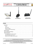
Wireless transceiver antenna mounting (optional)
NOTE: Complete this section only if your sign is equipped with a wireless transceiver.
Guidelines for antenna mounting
•
Install the antenna and bracket on a support structure other than the sign or the sign’s mounting brackets.
Do NOT drill a hole in the sign enclosure.
•
Install the antenna in a location that will allow optimum line-of-sight transmission and reception of signals
between the sending transceiver and the antenna. Do not install the antenna so that the sign is between the
sending transceiver and the receiving antenna.
•
Install the antenna in an unobstructed area, keeping adequate clearance from any objects that could block
the signal.
•
Install the antenna in a more elevated location than the sign and, if possible, keep it vertical.
Installation
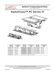
Mount the wireless antenna as shown:
The antenna should NOT be mounted
on the sign itself.
Inside the sign, a 2-foot cable (pn 1160-9008A)
connects the wireless transceiver to the 20-foot
antenna cable.
20-foot cable antenna cable
(pn 1160-9009A)
Figure 1: Wireless antenna mounting
20
Installation
AlphaEclipse 2500/2600/3500 Sign Installation Manual (9711-6024A)
February 14, 2006
Electrical installation
Electrical installation should only be attempted by a qualified electrician. Electrical connection must comply
with all applicable national and local codes.
&285$17'(
)8,7((/(9(
+D]DUGRXVYROWDJH
+,*+/($.$*(
&855(17
5DFFRUGHPHQW
DODWHUUH
LQGLVSHQVDEOH
DYDQWOH
UDFFRUGHPHQW
DXUHVHDX
&RQWDFWZLWKKLJKYROWDJH
PD\FDXVHGHDWKRUVHULRXV
LQMXU\
$OZD\VGLVFRQQHFWSRZHUWR
XQLWSULRUWRVHUYLFLQJ
(DUWKFRQQHFWLRQ
HVVHQWLDOEHIRUH
FRQQHFWLQJ
VXSSO\
Guidelines for electrical installation
•
Inspect all internal sign cabling for proper connection and seating.
•
All power wiring must be from circuit breaker-protected lines. However, a sign should NOT be connected
to a GFI-protected circuit.
•
A two-pole disconnect device must be installed in the building wiring for each branch circuit supplying
the sign.
•
The sign must be properly grounded according to the applicable codes (for example, NEC ARticle 250 and
600, and IEEE 1100-1999).
•
Run separate conduits for signal wires (for example, RS232, RS485) and for power wires. However, fiber
optic wire may be run in the same conduit with power wires.
•
All electrical connections must be watertight.
•
Use minimum 80° C copper wire only.
Utiliser uniquement un fil en cuivre pouvant supporter 85° C minimum.
•
Torque terminals to a minimum of 7 in/lbs and a maximum of 10in/lbs.
Serrer les bornes a 0,79 N/m minimum, mais pas a plus de 1,13 N/m.
Open the sign
1.
Open the sign.
•For an AlphaEclipse 2500/2600 sign, see “Opening and Closing an AlphaEclipse 2500/2600 sign” on
page 39.
•For an AlphaEclipse 3500 sign, see “Opening and Closing an AlphaEclipse 3500 sign” on page 41.
Connect communication wire
2.
If two signs are installed together, wire the two as either master/master (page 26) or master/slave
(page 27).
3.
Connect the sign(s) to a computer (“Computer-to-sign connections” on page 28).
Connect power to the sign
4.Run power wires to the sign using waterproof conduit.
Installation
120V
240V
LINE 1
LINE
LINE 2
NEUTRAL
GROUND
GROUND
Power Supply Terminal block
5.Connect power wires to the power supply terminal
block
•For AlphaEclipse 2500/2600 sign current requirements,
see Figure 4 on page 50.
•For AlphaEclipse 3500 sign current requirements, see
Figure 8 on page 54.
21
February 14, 2006
AlphaEclipse 2500/2600/3500 Sign Installation Manual (9711-6024A)
!DAPTIVE%XPLAINS
Why is it necessary to run two conduits to a sign?
It is not always necessary. Two conduits are only necessary when communication wire, like RS485 wire, is run to a sign from a
computer or from another sign. In these cases, one conduit would contain the sign’s power wires and the other conduit the
communication wires.
If power and communication wires are put in the same conduit, there is a chance the communication wires might pick up electrical
interference from the power wires. For example, when a live power cord is placed next to a stereo speaker wire, the interference from
this cord may cause the speaker to hum. In the case of a sign, this same effect could disrupt messages sent to the display.
On the other hand, fiber optic cable and power wires can share the same conduit because fiber optic cable is immune to electrical
interference.
Ground the sign
6.
The sign must be properly grounded in order to provide three types of protection:
•
Ground fault protection (see page 23) -- The sign must be wired to provide a permanent, low impedance
pathway to carry sign ground fault current. This is necessary in order to quickly clear a sign ground fault
by opening the power circuit to the sign.
Earth grounding a sign through some type of ground rod bonded to the sign is not sufficient ground fault protection.
•
Lightning strike protection (see page 23) -- An improperly wired sign could radiate electromagnetic fields
(EMF) that may damage or interfere with electronic equipment in or near the sign (see NEC Article 250.6)
•
Electronic equipment protection (see page 23) -- An improperly wired sign could radiate electromagnetic
fields (EMF) that may damage or interfere with electronic equipment in or near the sign (see NEC Article
250.6).
The sign grounding point
should be
connected to the earth ground (for example,
a grounding rod).
22
Installation
AlphaEclipse 2500/2600/3500 Sign Installation Manual (9711-6024A)
February 14, 2006
Ground fault protection
3IGNWITH'ROUND&AULT0ROTECTION
GROUNDFAULTCURRENTPATH
0ANEL
3ERVICE
3IGN
.
'ROUNDFAULT
.
"ECAUSEALOWRESISTANCEPATHWAYHASBEENPROVIDED
THELARGEAMOUNTOFCURRENTTHATFLOWSALONGTHISPATHWAY
WILLCAUSEABREAKERTOTRIPANDTHECIRCUITTOOPEN
,IGHTNING
ELECTRODE
,IGHTNING
ELECTRODE
3IGNWITHOUT'ROUND&AULT0ROTECTION
GROUNDFAULTCURRENTPATH
3ERVICE
0ANEL
3IGN
.
.
'ROUNDFAULT
.OGROUND
CONNECTION
.OPATHFORFAULTCURRENT
,IGHTNING
ELECTRODE
"ECAUSEOFTHERELATIVELYHIGHRESISTANCEOFANEARTHGROUND
ONLYASMALLAMOUNTOFCURRENTWILLFLOWTHROUGHTHELIGHTNINGELECTRODE
4HISSMALLCURRENTFLOWWILLPROBABLYNOTBEENOUGHTOOPENTHECIRCUIT
!SARESULTTHESIGNCASEWILLBECOMEASHOCKHAZARD
ANDPOSSIBLYAFIREHAZARDIFTHECURRENTLEVELISHIGHENOUGH
,IGHTNING
ELECTRODE
Lightning strike protection
A sign bonded to an earth ground has a means of dissipating the high voltage and current from a lightning
strike. The resistance of the grounding electrode should be as low as possible. However, damage can still occur to
a sign’s electronic equipment from lightning voltage transients.
Though some surge protection is incorporated into a sign, to protect a sign from high-voltage lightning
transients, surge protectors need to be installed at the panel boards (see NEC Article 280 and 284).
Electronic equipment protection
A common cause for the failure of sensitive electronic equipment is the presence of objectionable current (also
called objectionable neutral current) on grounding and bonding paths.
Objectionable neutral current can be caused by:
•
Errors in installation wiring
Installation
23
February 14, 2006
•
AlphaEclipse 2500/2600/3500 Sign Installation Manual (9711-6024A)
Improper neutral-to-case bonds (illustrated below)
/BJECTIONABLE.EUTRAL#URRENTCAUSEDBY)MPROPER.EUTRALTO#ASE"OND
NORMALCURRENTPATH
OBJECTIONABLENEUTRALCURRENTPATH
3ERVICESIDE
,OADSIDE
3ERVICE
0ANEL
3IGN
.
,IGHTNING
ELECTRODE
•
.
"ECAUSEOFANIMPROPERNEUTRALTOCASECONNECTIONSHOWNABOVE
ASHOCKHAZARDWILLBECREATEDBECAUSEOFPOTENTIALLYHAZARDOUSCURRENT
FLOWINGONCONDUCTIVESURFACESLIKETHESIGNgSHOUSING
)NADDITIONTHISCURRENTFLOWMAYCAUSEELECTROMAGNETICINTERFERENCE
THATDISRUPTSTHESIGNgSINTERNALELECTRONICS
,IGHTNING
ELECTRODE
Equipment-grounding conductor used to carry neutral current -- This situation arises when no separate
grounding wire is present when connecting power to a sign. NEC Article 250.32(B)(2) does permit a
neutral-ground bond to be used in a separate structure if all of the following three conditions are met:
(1) an equipment grounding connector is not run with the supply to the structure
(2) there are no continuous metallic paths bonded to the grounding system in both structures involved
(3) equipment ground fault protection has not been installed on the common AC service
Adaptive does not recommend using the equipment-grounding connector to carry neutral current as permitted by NEC 250.32(B)(2)
because it creates a potentially hazardous situation. For example, a future installer might connect cabling between the two structures
and this could create a dangerous parallel current path.
!DAPTIVE%XPLAINS
How can you tell if objectionable neutral current is present?
A true RMS microohm multimeter can be used to measure the voltage difference between the neutral and ground conductors. Though a
difference of OV is ideal, the voltage difference should not exceed 0.5V.
Test the sign’s exhaust fans
24
7.
Apply power to the sign.
8.
Push 1 on the sign’s internal power switch.
9.
If the exhaust fans are not already on, press the fan test button. All the exhaust fans should start.
Installation
AlphaEclipse 2500/2600/3500 Sign Installation Manual (9711-6024A)
February 14, 2006
Networking
AlphaEclipse signs can be connected together into a network of two or more signs (see “Sign-to-sign
connections” on page 25).
Also, in order to display messages, a sign must be connected to a computer that is running AlphaNET
software (see “Computer-to-sign connections” on page 28).
Sign-to-sign connections
Two or more signs can be set up as either
•
Master/Master signs (page 26) -- two or more signs that can display a different message. While the same
message could be sent to both Master signs, the messages may not appear at exactly the same time on the
signs
•
Master/Slave signs (page 27) -- all these signs display the same message at the same time. In this setup,
one sign is configured as the Master and all the others as Slave signs.
NOTE: When two or more signs are connected together, they must be properly terminated. See “RS485
termination” on page 44.
!DAPTIVE%XPLAINS
Does it matter if signs are set up as Master/Master or Master/Slave?
Only if it matters to you. the only difference between the two ways is that Master/Slave signs will all display the same message at the
same time. For example, this could be important if you have two signs mounted back-to-back near a highway. If these signs are set up as
Master/Slave signs, then highway traffic in both directions would see the same message.
How are signs set up to be Master/Master?
Signs are configured at the factory.
Is there any way to tell whether a sign is a Master or a Slave sign by just looking at it?
Probably not without turning the sign off and then on again. For more information, see “Serial address of a sign” on page 38.
Can a pair of Master/Master signs be changed to a Master/Slave pair (or vice versa)?
Yes -- by wiring the sign correctly and then by using AlphaNET software:
(1) First, wire the signs as Master/Master (page 26) or Master/Slave (page 27).
(2) You will need to know the serial address of the sign(s) you want to change. To find the address(es), turn the sign(s) off and then on
again. The serial address(es) will appear in the sign’s startup messages (see “Method 2” on page 38).
(3) Next, start the AlphaNET Diagnostics software by selecting Start > Programs > AlphNET > Diagnostics. Once Diagnostics starts,
check configure Sign (Advanced) and then click Select. Click OK at the prompt.
(4) Click Select Address and enter the serial address of the sign you wish to change. Then click OK.
(5) Check Set Other Options. Select either master or Slave from the Master/Slave pull down. Then click Send.
Networking
25
/VERVIEW
7IRING
$)0SWITCHES
!LPHA%CLIPSE
!LPHA%CLIPSE
3%2)!,
0/24
3%2)!,0/24
3%2)!,
4URBO
0/24
%XTENDER
BOARD
$)0SWITCHES
"ANK
3%2)!,0/24
-!34%23)'.
"ANK
"ANK
/.
4URBO
%XTENDER
BOARD
"ANK
3IGNALWIRE
CONDUIT
4%-039.#0/24
$)0SWITCHES
3%2)!,0/24
-!34%23)'.
'REEN
9ELLOW
"LACK
7HITE
2ED
3%2)!,
4URBO
0/24
%XTENDER
BOARD
$)0SWITCHES
"ANK
3%2)!,0/24
-!34%23)'.
"ANK
3ERIALADDRESSSWITCH/.
3ERIALADDRESSSWITCH/.
/.
3%2)!,
0/24
"ANK
3IGNALWIRE#ONTROLLERBOARDTOPVIEW
#ONTROLLERBOARDTOPVIEW
CONDUIT
'REEN
9ELLOW
"LACK
7HITE
2ED
4URBO
%XTENDER
BOARD
/NSOMESIGNSCONNECTIONSAREMADE
DIRECTLYTOTHE#ONTROLLERBOARDgS3%2)!,0/24
DIRECTLYTOTHE#ONTROLLERBOARDgS3%2)!,0/24
4%-039.#0/24
!
!
!
!
!
!
"LACK
"23!
"LACK !
2ED "23!
"23"
9ELLOW !
"23"
3()%,$
"3()%,$
NOTCONNECTED
!
"3()%,$
"2348$
'REEN !
"2348$
"2328$
2ED
!
"2328$
"'.$ 7HITE
!
"'.$
3%2)!,)/TERMINALBLOCK
3%2)!,)/TERMINALBLOCK
/NSOMESIGNSCONNECTIONSAREMADE
"LACK
9ELLOW
NOTCONNECTED
'REEN
2ED
7HITE
/.
"ANK
4%-039.
"LACK
2ED
3()%,$
-!34%23)'.SERIALADDRESS
-!34%23)'.SERIALADDRESS
23TERMINATION/.SWITCHESANDBOTH/.
23TERMINATION/.SWITCHESANDBOTH/.
23TERMINATION/.SWITCHESANDBOTH/.
23TERMINATION/.SWITCHESANDBOTH/.
)FTHISSIGNISCONNECTEDTOA#ONVERTER"OX)))TURNSWITCHESANDBOTH/&&
$2!7).'2%6)3)/.
)FTHISSIGNISCONNECTEDTOA#ONVERTER"OX)))TURNSWITCHESANDBOTH/&&
$
3ERIALADDRESSSWITCH/.
3ERIALADDRESSSWITCH/.
$)0SWITCHES
'REEN
9ELLOW
"LACK
7HITE
2ED
#ONTROLLERBOARDTOPVIEW
#ONTROLLERBOARDTOPVIEW
/NSOMESIGNSCONNECTIONSAREMADE
DIRECTLYTOTHE#ONTROLLERBOARDgS3%2)!,0/24
DIRECTLYTOTHE#ONTROLLERBOARDgS3%2)!,0/24
4%-039.#0/24
-!34%23)'.
'REEN
9ELLOW
"LACK
7HITE
2ED
!
!
!
!
!
!
"LACK
"23!
"LACK !
"LACK
2ED "23!
"23"
9ELLOW !
2ED
"23"
3()%,$
"3()%,$
NOTCONNECTED
3()%,$
!
"3()%,$
"2348$
'REEN !
23OUTDOORCABLE
"2348$
23OUTDOORCABLE
"2328$
2ED
PN
!
"2328$
PN
"'.$ 7HITE
!
"'.$
3%2)!,)/TERMINALBLOCK
3%2)!,)/TERMINALBLOCK
/NSOMESIGNSCONNECTIONSAREMADE
"LACK
9ELLOW
NOTCONNECTED
'REEN
2ED
7HITE
-!34%23)'.SERIALADDRESS
-!34%23)'.SERIALADDRESS
4WOSIGNSCONNECTEDASA-ASTER-ASTERPAIRCANEACHDISPLAYAUNIQUEMESSAGEUNLIKEA-ASTER3LAVESIGNPAIRWHICHALWAYSDISPLAYSTHESAMEMESSAGEATTHESAMETIME
4WOSIGNSCONNECTEDASA-ASTER-ASTERPAIRCANEACHDISPLAYAUNIQUEMESSAGEUNLIKEA-ASTER3LAVESIGNPAIRWHICHALWAYSDISPLAYSTHESAMEMESSAGEATTHESAMETIME
)NA-ASTER-ASTERSIGNPAIRAMESSAGECANBEDISPLAYEDON-ASTERSIGNBYSENDINGTHEMESSAGETOSERIALADDRESSORDISPLAYEDON-ASTERSIGNBYSENDINGITTOSERIALADDRESS
)NA-ASTER-ASTERSIGNPAIRAMESSAGECANBEDISPLAYEDON-ASTERSIGNBYSENDINGTHEMESSAGETOSERIALADDRESSORDISPLAYEDON-ASTERSIGNBYSENDINGITTOSERIAL
!LSOAMESSAGECANBEDISPLAYEDONBOTH-ASTERSIGNSBYBROADCASTINGTHEMESSAGETOSERIALADDRESS
!LSOAMESSAGECANBEDISPLAYEDONBOTH-ASTERSIGNSBYBROADCASTINGTHEMESSAGETOSERIALADDRESS
4ODISPLAYTHETEMPERATUREONSIGNSINA-ASTER-ASTERNETWORKATEMPERATUREPROBEMUSTBECONNECTEDTOEACHSIGN/THERWISETHEWORD%22WILLAPPEARINPLACEOFTHETEMPERATURE
4ODISPLAYTHETEMPERATUREONSIGNSINA-ASTER-ASTERNETWORKATEMPERATUREPROBEMUSTBECONNECTEDTOEACHSIGN/THERWISETHEWORD%22WILLAPPEARINPLACEOFTHETEM
)NA-ASTER-ASTERSIGNNETWORKTHETIMEISSYNCHRONIZEDWHENEVERAMESSAGEISSENTUSING!LPHA.%4SOFTWARE
)NA-ASTER-ASTERSIGNNETWORKTHETIMEISSYNCHRONIZEDWHENEVERAMESSAGEISSENTUSING!LPHA.%4SOFTWARE
-ASTER-ASTERSIGNCONNECTION
-ASTER-ASTERSIGNCONNECTION
/VERVIEW
7IRING
26
$)0SWITCHES
February 14, 2006
AlphaEclipse 2500/2600/3500 Sign Installation Manual (9711-6024A)
Master/Master sign-to-sign wiring
Networking
/VERVIEW
7IRING
Networking
$)0SWITCHES
3%2)!,
0/24
4URBO
%XTENDER
BOARD
"ANK
23OUTDOORCABLE
PN
4%-039.#0/24
232ED
23"LACK
3()%,$
/.
23TERMINATION/.SWITCHESANDBOTH/.
)FTHISSIGNISCONNECTEDTOA#ONVERTER"OX)))THENSWITCHESANDBOTH/&&
3ERIALADDRESSSWITCH/.
$)0SWITCHES
3%2)!,0/24
"ANK
#ONTROLLERBOARDTOPVIEW
-!34%23)'.
'REEN
9ELLOW
"LACK
7HITE
2ED
23OUTDOORCABLE
PN
3IGNALWIRE
CONDUIT
"LACK
9ELLOW
NOTCONNECTED
'REEN
2ED
7HITE
!
!
!
!
!
!
"23!
"23"
"3()%,$
"2348$
"2328$
"'.$
3%2)!,
0/24
4URBO
%XTENDER
BOARD
3ERIALADDRESSSWITCH/.
-ASTER3LAVEMODE3LAVESWITCH/.
23TERMINATION/.SWITCHESANDBOTH/.
$)0SWITCHES
3%2)!,0/24
"ANK
#ONTROLLERBOARDTOPVIEW
3,!6%3)'.
'REEN
9ELLOW
"LACK
7HITE
2ED
3%2)!,)/TERMINALBLOCK
"LACK
2ED
3()%,$
/NSOMESIGNSCONNECTIONSAREMADE
DIRECTLYTOTHE#ONTROLLERBOARDgS3%2)!,0/24
"23!
"23"
"3()%,$
"2348$
"2328$
"'.$
"ANK
$2!7).'2%6)3)/.
4%-039.#0/24
232ED
23"LACK
3()%,$
"LACK
2ED
3()%,$
3,!6%3)'.SERIALADDRESS
3%2)!,)/TERMINALBLOCK
!
!
!
!
!
!
4HE-ASTER
AND
3LAVESIGNS
MUSTBETHE
SAMESIZE
/NSOMESIGNSCONNECTIONSAREMADE
DIRECTLYTOTHE#ONTROLLERBOARDgS3%2)!,0/24
"LACK
9ELLOW
NOTCONNECTED
'REEN
2ED
7HITE
-!34%23)'.SERIALADDRESS
)N-ASTER3LAVESIGNNETWORKTHETIMEISSYNCHRONIZEDATTHESTARTOFEACHHOURANDWHENEVERAMESSAGEISSENTUSING!LPHA.%4SOFTWARE
4ODISPLAYTHETEMPERATUREONSIGNSINA-ASTER3LAVENETWORKATEMPERATUREPROBEMUSTBECONNECTEDTOTHE-ASTERSIGN
4ODOTHISSENDALLMESSAGESTOSERIALADDRESSORTOALLTHESERIALADDRESSESANDSOON
/.
!LPHA%CLIPSE
4WOSIGNSCONNECTEDASA-ASTER3LAVEPAIRWILLBOTHDISPLAYTHESAMEMESSAGEATTHESAMETIME-ESSAGESSHOULDBESENTTOBOTHTHE-ASTERAND3LAVESIGNS
-ASTER3LAVESIGNCONNECTION
AlphaEclipse 2500/2600/3500 Sign Installation Manual (9711-6024A)
February 14, 2006
Master/Slave sign-to-sign wiring
27
February 14, 2006
AlphaEclipse 2500/2600/3500 Sign Installation Manual (9711-6024A)
Computer-to-sign connections
In order to display messages, a sign must be connected to a computer that is running AlphaNET software.
(This computer is referred to as the “messaging computer”).
There are a number of ways to connect the messaging computer to a sign:
Wire
There are several ways to connect a sign directly to a computer:
•
Converter box III (page 29) -- using RS485 outdoor wire (pn 7124-0203), a sign can be connected to a
computer that could be up to 4000 feet away from the sign.
•
Fiber optic (page 30) -- using a factory installed fiber optic mini-modem inside a sign and another minimodem attached to a computer, a sign can be connected to a computer that could be up to 2 miles away
from the sign. Fiber optic cable is immune to electrical interference so the cable can be placed in the same
conduit as the sign’s power wires.
•
Ethernet (page 31) -- a sign can be connected to an Ethernet network by wiring a Lantronix MSS485
interface to a sign.
•
External connection box (page 32 and page 33) -- usually placed close to the sign. Messages are sent to the
sign by connecting a computer or IR Message Loader to the connection box.
Modem
By placing a factory installed modem inside a sign and attaching another modem to a computer, messages can
be sent to a sign through ordinary phone lines (page 34).
Wireless
For this option, a factory installed wireless transceiver is placed inside the sign and another transceiver is
connected to a computer. Wireless transceivers can connect to a sign up to 40 miles away, but actual distance can
vary greatly depending on the local environment, obstructions, electrical interference, and so on (page 35, page 36
and page 37).
28
Networking
/VERVIEW
7IRING
Networking
$)0SWITCHES
'.$"LUE
2328$/RANGE
2348$'REEN
232ED
3()%,$
23"LACK
3%2)!,0/24ON#ONTROLLERBOARD
"ANK
3ERIALADDRESSSWITCH/.
23TERMINATION/.SWITCHESANDBOTH/.
$)0SWITCHES
3%2)!,0/24
#ONTROLLERBOARD$)0SWITCHES
#ONVERTER"OX)))
PN
3()%,$
232ED
23"LACK
3ETTHISSWITCH
TO4%2-).!4%$
/.
!LSOEACHSIGNSHOULDHAVEITSOWNUNIQUESERIALADDRESS
THEFIRSTSIGNSHOULDBESETTOSERIALADDRESSASSHOWN
THESECONDSIGNSHOULDBESETTOSERIALADDRESSANDSOON
3()%,$
]
&ROM
#ONVERTER
"OX)))
$2!7).'2%6)3)/.
232ED
23"LACK
3%2)!,0/24ON#ONTROLLERBOARD
-%4(/$3%2)!,0/24CONNECTION
)FMORETHANONESIGNISCONNECTEDTOA#ONVERTER"OX)))
THENTHE$)0SWITCHSETTINGSWILLBEDIFFERENT
&OREXAMPLEONLYTHE#ONVERTER"OX)))ANDTHELASTSIGN
ONTHENETWORKNEEDTOBETERMINATED!LLOTHERSIGNSSHOULD
HAVETHEIRTWO23TERMINATION$)0SWITCHESSETTO/&&
5SETHE$)0SWITCHSETTINGSSHOWNONTHELEFT
WHENCONNECTINGASINGLESIGNTOA#ONVERTER"OX)))
-%4(/$/THERWISEWIRETHE#ONVERTER"OX)))DIRECTLYTOTHE
3%2)!,0/24ONTHESIGNgS#ONTROLLERBOARDRIGHT
-%4(/$)FASIGNHASA3%2)!,)/TERMINALBLOCKTHENWIRETHE
#ONVERTER"OX)))TOTHISBLOCKABOVE
4HEREARETWOMETHODSOFWIRINGA#ONVERTER"OX)))TOASIGN
3%2)!,)/
TERMINALBLOCK
"ANK
3()%,$
23
23
#ONVERTER"OX)))PN
)NORDERTODISPLAYMESSAGESONASIGNTHEMESSAGINGCOMPUTER
MUSTBECONNECTEDTOTHESIGNSUCHASWITHA#ONVERTER"OX)))
!LPHA%CLIPSE
-ESSAGINGCOMPUTERRUNNING
!LPHA.%4SOFTWARE
23CABLE
PN
23OUTDOORCABLE
PN
-%4(/$3%2)!,)/TERMINALBLOCKCONNECTION
!LPHA%CLIPSESIGN
FEET
UPTOFEET
#ONVERTER"OX)))23
AlphaEclipse 2500/2600/3500 Sign Installation Manual (9711-6024A)
February 14, 2006
Converter Box III (RS485) computer-to-sign connection
29
/VERVIEW
7IRING
3()%,$"LACKLARGEWIRE
2348$'REEN
2328$7HITE
'.$"LACK
62ED
3%2)!,0/24ON#ONTROLLERBOARD
3ERIALADDRESSSWITCH/.
23TERMINATION/.SWITCHESANDBOTH/.
$)0SWITCHES
"ANK
"ANK
)NSIDESIGN
&IBEROPTICMINIMODEMS
"LACK"OX-%!&34
&IBEROPTIC
MODEM
48$
28$
/.
28$
48$
&IBEROPTIC
MODEM
$2!7).'2%6)3)/.
$"TO$"CABLEPINOUT
FIBEROPTICMODEMTOMESSAGINGCOMPUTER
$"
$"
$#$
2328$
2348$
$42
'.$
$32
243
#43
NOTCONNECTED !LSOEACHSIGNSHOULDHAVEITSOWNUNIQUESERIALADDRESS
THEFIRSTSIGNSHOULDBESETTOSERIALADDRESSASSHOWN
THESECONDSIGNSHOULDBESETTOSERIALADDRESSANDSOON
&OREXAMPLEONLYTHEFIRSTANDTHELASTSIGNSINTHENETWORK
NEEDTOBETERMINATED!LLOTHERSIGNSSHOULDHAVETHEIR
TWO23TERMINATION$)0SWITCHESSETTO/&&
)FMORETHANONESIGNISCONNECTEDTOAFIBEROPTIC
MODEMTHENTHE$)0SWITCHSETTINGSWILLBEDIFFERENT
5SETHE$)0SWITCHSETTINGSSHOWNONTHELEFT
WHENCONNECTINGASINGLESIGNTOAFIBEROPTICMODEM
4HISWIRINGSHOWNHEREASSUMESEACH
MODEMISSETTO$#%
4HEDEFAULTSETTINGIS$#%
4HEFIBEROPTICMODEMSCANBECONFIGURED
ASEITHER$#%OR$4%DEVICES
!DAPTER
PN
)NORDERTODISPLAYMESSAGESONASIGNTHEMESSAGINGCOMPUTER
MUSTBECONNECTEDTOTHESIGNSUCHASWITHFIBEROPTICMODEMS
&IBEROPTICMODEMSALLOWAMESSAGINGCOMPUTERTOCONNECT
TOASIGNUPTOMILESAWAYFROMTHECOMPUTER4HEFIBEROPTIC
-ESSAGINGCOMPUTER
RUNNING!LPHA.%4SOFTWARE MODEMSSENDDATATOASIGNOVERANOPTICAL23CONNECTION
$"TO$"CABLE
"LACK"OX"#
!LPHA%CLIPSE
28
3%2)!,0/24
UPTOMILES
&IBEROPTICCABLES
28
#ONTROLLERBOARD$)0SWITCHES
&IBEROPTICMODEMADAPTER
INSIDESIDEPN
!LPHA%CLIPSESIGN
28
$!4!
48
&IBEROPTICCONNECTION
28
$!4!
30
$!4!
$!4!
48
48
48
$)0SWITCHES
February 14, 2006
AlphaEclipse 2500/2600/3500 Sign Installation Manual (9711-6024A)
Fiber optic computer-to-sign connection
Networking
23OUTDOORCABLE
PN
'.$"LUE
2328$/RANGE
"ANK
3ERIALADDRESSSWITCH/.
23TERMINATION/.SWITCHESANDBOTH/.
$)0SWITCHES
3%2)!,0/24
"ANK
/.
&LOAT3()%,$SWITCH/&&
/&&
]
&ROM
,ANTRONIX
-33
$2!7).'2%6)3)/.
WIRE23SWITCHESAND/.
WIRE23TERMINATIONON
SWITCH/.SWITCH/&&
WIRE28BIASINGSWITCHESAND/.
/.
3()%,$
232ED
23"LACK
3%2)!,0/24ON#ONTROLLERBOARD
-%4(/$3%2)!,0/24CONNECTION
,ANTRONIX-33$)0SWITCHES
!LSOEACHSIGNSHOULDHAVEITSOWN
UNIQUESERIALADDRESSTHEFIRSTSIGNSHOULD
BESETTOSERIALADDRESSASSHOWN
THESECONDSIGNSHOULDBESETTOSERIAL
ADDRESSANDSOON
5SETHE$)0SWITCHSETTINGSSHOWN
ONTHELEFTWHENCONNECTINGASINGLE
SIGNTOA,ANTRONIX-33
)FMORETHANONESIGNISCONNECTED
TOA,ANTRONIX-33THENTHE
$)0SWITCHSETTINGSWILLBEDIFFERENT
&OREXAMPLEONLYTHELASTSIGNSHOULD
HAVEITSTWO23TERMINATION$)0
SWITCHESSETTO/&&
-%4(/$/THERWISEWIRETHE,ANTRONIX-33DIRECTLYTOTHE
3%2)!,0/24ONTHESIGNgS#ONTROLLERBOARDRIGHT
-%4(/$)FASIGNHASA3%2)!,)/TERMINALBLOCKTHENWIRETHE
,ANTRONIX-33TOTHISBLOCKABOVE
4HEREARETWOMETHODSOFWIRINGA,ANTRONIX-33TOASIGN
CONSOLE
2348$'REEN
,!.42/.)8
,ANTRONIX-33PN!
SERIAL
232ED
3%2)!,)/
TERMINALBLOCK
OK
3()%,$
23"LACK
3%2)!,0/24ON#ONTROLLERBOARD
48!
48"
3()%,$
-334
-ESSAGINGCOMPUTER
RUNNING!LPHA.%4SOFTWARE
"ECAUSEAN!LPHA%CLIPSESIGNCANNOTBECONNECTEDDIRECTLYTOAN
%THERNETNETWORKTHE,ANTRONIX-33MUSTBEUSEDASANINTERFACE
!LSOSINCETHELENGTHOFAN%THERNET,!.ISVIRTUALLYUNLIMITED
THEMESSAGINGCOMPUTERCOULDBEVERYFARAWAYFROMASIGN
)NORDERTODISPLAYMESSAGESONASIGNTHEMESSAGINGCOMPUTER
MUSTBECONNECTEDTOTHESIGNSUCHASWITHA,ANTRONIX-33
!LPHA%CLIPSE
LINK
#ONTROLLERBOARD$)0SWITCHES
3()%,$
232ED
23"LACK
3()%,$
2ED
"LACK
"!3%4
%THERNET
,ANTRONIX-33
PN!
SERIAL
-334
OK
-%4(/$3%2)!,)/TERMINALBLOCKCONNECTION
!LPHA%CLIPSESIGN
VDC
RESET
"!3%4
UPTOFEET
CONSOLE
SERIAL
/VERVIEW
7IRING
SERIAL
POWER
$)0SWITCHES
LINK
VDC
POWER
RESET
Networking
,!.42/.)8
"!3%4
%THERNETCONNECTION
AlphaEclipse 2500/2600/3500 Sign Installation Manual (9711-6024A)
February 14, 2006
Ethernet computer-to-sign connection
31
Overview
Wiring
32
DIP switches
6-position Modular Network Adapter
(pn 4331-0604)
Blue or
White
Bank 2
Bank 1
ON
METHOD 2: Otherwise, wire the box directly to the SERIAL PORT on the sign's Controller board (right).
Also, each sign should have its own, unique serial address:
the first sign should be set to serial address 01 (as shown),
the second sign should be set to serial address 02, and so on.
If more than one sign is connected to a connection box,
then the DIP switch settings will be different.
For example, only the first and the last signs in the network
need to be terminated. All other signs should have their
two, RS485 termination DIP switches set to OFF.
Use the DIP switch settings shown on the left
when connecting a single sign to an External connection box.
METHOD 1: If a sign has a SERIAL I/O terminal block, then wire the box to this block (above).
}
DRAWING REVISION 2
Wire from White terminal
Wire from Red terminal
From
External
connection
box
SERIAL PORT (on Controller board)
Wire from Green terminal
2
3
4
RJ12-to-DB9 cable
(pn 1036-9010)
connects to computer
GND (Blue)
Serial address = 01 (switch #1 ON)
RS485 termination = ON (switches #1 and #2 both ON)
DIP switches
SERIAL PORT
GND wire must be
connected to the White
wire on the 6-position
Modular Adapter
Green Yellow
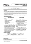
There are two methods of wiring an External connection box to a sign:
SERIAL I/O
terminal block
GND
RS232 TXD
RS232 RXD
White or
Blue
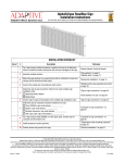
External connection box (RS232) computer-to-sign connection
METHOD 2 — SERIAL PORT connection
The RS232 External connection box can be up to 50 feet from a sign.
The computer must have an external 9-pin RS232 COM port available.
In order to display messages on a sign or troubleshoot a sign,
a messaging computer can be connected directly to a sign.
AlphaEclipse™ 2500/2600/3500
RS232 RXD (Orange)
RS232 TXD (Green)
RS485 - (Red)
SHIELD
RS485 + (Black)
SERIAL PORT (on Controller board)
Controller board DIP switches:
6
7
2
3
4
Red Black
RS232 External connection box (dotted line below)
This is just a waterproof enclosure
with a 6-position Modular Network Adapter inside.
RS485 outdoor cable (pn 7124-0203) can be used if the bare shield wire is connected
to the white terminal (GND) on the 6-position Modular Network Adapter.
External connection box
METHOD 1 — SERIAL I/O terminal block connection:
Sign mounting pole
AlphaEclipse™ sign
External connection box (RS232) — for a computer connection
February 14, 2006
AlphaEclipse 2500/2600/3500 Sign Installation Manual (9711-6024A)
Networking
/VERVIEW
7IRING
Networking
$)0SWITCHES
'.$"LUE
2328$/RANGE
2348$'REEN
232ED
3()%,$
23"LACK
3%2)!,0/24ON#ONTROLLERBOARD
"ANK
!LPHA%CLIPSE
9ELLOW
"LACK
POSITION-ODULAR.ETWORK!DAPTER
PN
'REEN
2ED
23%XTERNALCONNECTIONBOXDOTTEDLINEBELOW
4HISISJUSTAWATERPROOFENCLOSURE
WITHAPOSITION-ODULAR.ETWORK!DAPTERINSIDE
"ANK
/.
!LSOEACHSIGNSHOULDHAVEITSOWNUNIQUESERIALADDRESS
THEFIRSTSIGNSHOULDBESETTOSERIALADDRESSASSHOWN
THESECONDSIGNSHOULDBESETTOSERIALADDRESSANDSOON
)FMORETHANONESIGNISCONNECTEDTOACONNECTIONBOX
THENTHE$)0SWITCHSETTINGSWILLBEDIFFERENT
&OREXAMPLEONLYTHEFIRSTANDTHELASTSIGNSINTHENETWORK
NEEDTOBETERMINATED!LLOTHERSIGNSSHOULDHAVETHEIR
TWO23TERMINATION$)0SWITCHESSETTO/&&
5SETHE$)0SWITCHSETTINGSSHOWNONTHELEFT
WHENCONNECTINGASINGLESIGNTOAN%XTERNALCONNECTIONBOX
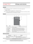
-%4(/$/THERWISEWIRETHEBOXDIRECTLYTOTHE3%2)!,0/24ONTHESIGNgS#ONTROLLERBOARDRIGHT
-%4(/$)FASIGNHASA3%2)!,)/TERMINALBLOCKTHENWIRETHEBOXTOTHISBLOCKABOVE
4O
)2-ESSAGE
,OADER
]
&ROM
%XTERNAL
CONNECTION
BOX
$2!7).'2%6)3)/.
23
23
3()%,$
3%2)!,0/24ON#ONTROLLERBOARD
-%4(/$3%2)!,0/24CONNECTION
4HISCONNECTIONBOXISTYPICALLYATTACHEDNEARTHEBASEOFTHESIGNgSMOUNTINGPOLE
!N23%XTERNALCONNECTIONBOXALLOWSAN)2-ESSAGE,OADERTODOWNLOADMESSAGESTOASIGN
)NORDERTODISPLAYMESSAGESONASIGNAN)2-ESSAGE,OADERCANBEUSEDTOTRANSFERMESSAGESFROM
ACOMPUTERTOAN!LPHA%CLIPSESIGN&ORMOREINFORMATIONSEE(OWTOUSETHE)2-ESSAGE,OADERTO
$ISPLAY-ESSAGESON!LPHA%CLIPSE3IGNSPN
4HEREARETWOMETHODSOFWIRINGAN%XTERNALCONNECTIONBOXTOASIGN
3ERIALADDRESSSWITCH/.
23TERMINATION/.SWITCHESANDBOTH/.
$)0SWITCHES
3%2)!,0/24
#ONTROLLERBOARD$)0SWITCHES
3()%,$
23
23
3%2)!,)/
TERMINALBLOCK
%XTERNALCONNECTIONBOX
23OUTDOORCABLEPN
-%4(/$3%2)!,)/TERMINALBLOCKCONNECTION
3IGNMOUNTINGPOLE
!LPHA%CLIPSESIGN
%XTERNALCONNECTIONBOX23FORAN)2-ESSAGE,OADER
AlphaEclipse 2500/2600/3500 Sign Installation Manual (9711-6024A)
February 14, 2006
External connection box (RS485) computer-to-sign connection
33
/VERVIEW
7IRING
34
$)0SWITCHES
'.$"LUE
2328$/RANGE
2348$'REEN
232ED
3()%,$
23"LACK
3%2)!,0/24ON#ONTROLLERBOARD
"ANK
3ERIALADDRESSSWITCH/.
23TERMINATION/.SWITCHESANDBOTH/.
$)0SWITCHES
3%2)!,0/24
#ONTROLLERBOARD$)0SWITCHES
-%4(/$3%2)!,)/TERMINALBLOCKCONNECTION
2ECEIVINGMODEMINSIDESIGNPN
!LPHA%CLIPSESIGN
-ODEMCONNECTION
"ANK
/.
]
&ROM
MODEM
3URGESUPRESSORBOARD
2%$
2).'
'REEN4)0
2ED2).'
'2%%.
4)0
]
4O
TELEPHONE
SERVICE
WIRETO$"CABLE
PN
!LSOEACHSIGNSHOULDHAVEITSOWNUNIQUESERIAL
ADDRESSTHEFIRSTSIGNSHOULDBESETTOSERIAL
ADDRESSASSHOWNTHESECONDSIGNSHOULD
BESETTOSERIALADDRESSANDSOON
)FMORETHANONESIGNISCONNECTEDTOAMODEM
THENTHE$)0SWITCHSETTINGSWILLBEDIFFERENT
&OREXAMPLEONLYTHEFIRSTANDTHELASTSIGNSIN
THENETWORKNEEDTOBETERMINATED!LLOTHERSIGNS
SHOULDHAVETHEIRTWO23TERMINATION$)0
SWITCHESSETTO/&&
5SETHE$)0SWITCHSETTINGSSHOWNONTHELEFT
WHENCONNECTINGASINGLESIGNTOAMODEM
2*
PHONE
CORD
FROM
MODEM
3%2)!,)/
TERMINALBLOCK
'.$7HITE
2328$2ED
2348$"LACK
'.$7HITE
2328$2ED
2348$"LACK
]
/.
&ROM
MODEM
$2!7).'2%6)3)/.
!4(2".97
-ODEM!4COMMANDSETUPSTRING
3WITCH/.-ODEMIGNORES$42
3WITCH/.$ISPLAYRESULTCODES
3WITCH/.$ONOTECHOOFFLINECOMMANDS
3WITCH/.2ECOGNIZE!4COMMANDS
WIRETO$"CABLE
PN
3%2)!,0/24ON#ONTROLLERBOARD
-ODEM$)0SWITCHSETTINGS
-%4(/$3%2)!,0/24CONNECTION
-ODEMSCANCONNECTTOASIGNTHATISALMOSTANYWHERE
(OWEVERASIGNMUSTHAVEITSOWNPHONELINE
)NORDERTODISPLAYMESSAGESONASIGNTHEMESSAGINGCOMPUTER
MUSTBECONNECTEDTOTHESIGNSUCHASWITHAPAIROFTELEPHONE
MODEMSA4RANSMITTINGMODEMATTACHEDTOTHEMESSAGING
COMPUTERANDA2ECEIVINGMODEMATTACHEDTOASIGN
4HEREARETWOMETHODSOFWIRINGTHE2ECEIVINGMODEM
TOASIGN
-%4(/$)FASIGNHASA3%2)!,)/TERMINALBLOCK
THENWIRETHEMODEMTOTHISBLOCKLEFT
-%4(/$/THERWISEWIRETHEMODEMDIRECTLYTOTHE
3%2)!,0/24ONTHESIGNgS#ONTROLLERBOARDRIGHT
-ESSAGINGCOMPUTER
RUNNING!LPHA.%4SOFTWARE
SUPPLIEDWITHMODEM
23CABLE
4RANSMITTINGMODEMPN
!LPHA%CLIPSE
February 14, 2006
AlphaEclipse 2500/2600/3500 Sign Installation Manual (9711-6024A)
Modem computer-to-sign connection
Networking
/VERVIEW
7IRING
Networking
$)0SWITCHES
'.$"LUE
2328$/RANGE
2348$'REEN
232ED
3()%,$
23"LACK
3%2)!,0/24ON#ONTROLLERBOARD
"ANK
"ANK
]
&ROM
TRANSCEIVER
WIRETO$"CABLE
PN
/.
!LSOEACHSIGNSHOULDHAVEITSOWNUNIQUESERIALADDRESS
THEFIRSTSIGNSHOULDBESETTOSERIALADDRESSASSHOWN
THESECONDSIGNSHOULDBESETTOSERIALADDRESSANDSOON
)FMORETHANONESIGNISCONNECTEDTOATRANSCEIVER
THENTHE$)0SWITCHSETTINGSWILLBEDIFFERENT
&OREXAMPLEONLYTHEFIRSTANDTHELASTSIGNSINTHE
NETWORKNEEDTOBETERMINATED!LLOTHERSIGNSSHOULD
HAVETHEIRTWO23TERMINATION$)0SWITCHESSETTO/&&
5SETHE$)0SWITCHSETTINGSSHOWNONTHELEFT
WHENCONNECTINGASINGLESIGNTOAWIRELESSTRANSCEIVER
-%4(/$/THERWISEWIRETHE2ECEIVETRANSCEIVERDIRECTLY
TOTHE3%2)!,0/24ONTHESIGNgS#ONTROLLERBOARDRIGHT
-%4(/$)FASIGNHASA3%2)!,)/TERMINALBLOCKTHEN
WIRETHE2ECEIVETRANSCEIVERTOTHISBLOCKABOVE
'.$7HITE
2328$"LACK
2348$2ED
]
&ROM
TRANSCEIVER
$2!7).'2%6)3)/.
WIRETO$"CABLE
PN
3%2)!,0/24ON#ONTROLLERBOARD
-%4(/$3%2)!,0/24CONNECTION
7IRELESSTRANSCEIVERSCANCONNECTTOASIGNTHATISUPTOMILESAWAY!CTUAL
DISTANCEDEPENDSONTHELOCALENVIRONMENTOBSTRUCTIONSELECTRICAL
INTERFERENCEANDSOON
)NORDERTODISPLAYMESSAGESONASIGNTHEMESSAGINGCOMPUTERMUSTBE
CONNECTEDTOTHESIGNSUCHASWITHAPAIROFWIRELESSTRANSCEIVERSA-ASTER
TRANSCEIVERATTACHEDTOTHEMESSAGINGCOMPUTERANDA2ECEIVETRANSCEIVER
ATTACHEDTOASIGN
!LPHA%CLIPSE
4HEREARETWOMETHODSOFCONNECTINGTHE2ECEIVEWIRELESS
TRANSCEIVERTOASIGN
3%2)!,)/
TERMINALBLOCK
'.$7HITE
2328$"LACK
2348$2ED
-ESSAGINGCOMPUTER
RUNNING!LPHA.%4SOFTWARE
23CABLE
SUPPLIEDWITHTRANSCEIVER
-ASTERTRANSCEIVER
3ERIALADDRESSSWITCH/.
23TERMINATION/.SWITCHESANDBOTH/.
$)0SWITCHES
3%2)!,0/24
#ONTROLLERBOARD$)0SWITCHES
-%4(/$3%2)!,)/TERMINALBLOCKCONNECTION
2ECEIVETRANSCEIVERINSIDESIGN
!LPHA%CLIPSESIGN
7IRELESSCONNECTION,OCUSTRANSCEIVER
AlphaEclipse 2500/2600/3500 Sign Installation Manual (9711-6024A)
February 14, 2006
Wireless (Locus transceiver) computer-to-sign connection
35
/VERVIEW
7IRING
36
$)0SWITCHES
"ANK
#OAXCABLEFEET
PN!
/.
3%2)!,0/24ON#ONTROLLERBOARD
!LSOEACHSIGNSHOULDHAVEITSOWNUNIQUESERIALADDRESS
THEFIRSTSIGNSHOULDBESETTOSERIALADDRESSASSHOWN
THESECONDSIGNSHOULDBESETTOSERIALADDRESSANDSOON
)FMORETHANONESIGNISCONNECTEDTOATRANSCEIVER
THENTHE$)0SWITCHSETTINGSWILLBEDIFFERENT
&OREXAMPLEONLYTHEFIRSTANDTHELASTSIGNSINTHE
NETWORKNEEDTOBETERMINATED!LLOTHERSIGNSSHOULD
HAVETHEIRTWO23TERMINATION$)0SWITCHESSETTO/&&
$2!7).'2%6)3)/.
!LPHA2&TRANSCEIVERSHAVEANINDOORTRANSMISSIONRANGE
OFTOFEETANDANOUTDOORRANGEOFFEETLINEOFSITE
)NORDERTODISPLAYMESSAGESONASIGNTHEMESSAGINGCOMPUTERMUSTBE
CONNECTEDTOTHESIGNSUCHASWITHAPAIROFWIRELESSTRANSCEIVERSASERVER
TRANSCEIVERATTACHEDTOTHEMESSAGINGCOMPUTERANDACLIENTTRANSCEIVER
ATTACHEDTOASIGN
!LPHA%CLIPSE
5SETHE$)0SWITCHSETTINGSSHOWNONTHELEFT
WHENCONNECTINGASINGLESIGNTOAWIRELESSTRANSCEIVER
6$#2ED
6$#"LACK
48$"ROWN
28$/RANGE
%'.$"LACK
-ESSAGINGCOMPUTER
RUNNING!LPHA.%4SOFTWARE
!LPHA2&E
WIRELESSTRANSCEIVER
"ANK
!LPHA2&3ERVER
3ERIALADDRESSSWITCH/.
23TERMINATION/.SWITCHESANDBOTH/.
$)0SWITCHES
3%2)!,0/24
#ONTROLLERBOARD$)0SWITCHES
!NTENNA
CONNECTION
3IGN
CASING
#LIENTTRANSCEIVERINSIDESIGN
!LPHA%CLIPSESIGN
23CABLE
SUPPLIEDWITHTRANSCEIVER
7IRELESSCONNECTION!LPHA2&TRANSCEIVER
February 14, 2006
AlphaEclipse 2500/2600/3500 Sign Installation Manual (9711-6024A)
Wireless (Alpha RF900 transceiver) computer-to-sign connection
Networking
/VERVIEW
7IRING
'.$"LUE
2328$/RANGE
2348$'REEN
232ED
3()%,$
23"LACK
3%2)!,0/24ON#ONTROLLERBOARD
"ANK
3ERIALADDRESSSWITCH/.
23TERMINATION/.SWITCHESANDBOTH/.
$)0SWITCHES
3%2)!,0/24
#ONTROLLERBOARD$)0SWITCHES
-%4(/$3%2)!,)/TERMINALBLOCKCONNECTION
"ANK
3%2)!,)/
TERMINALBLOCK
]
&ROM
-AX3TREAM
4RANSCEIVER
WIRETO$"CABLE
PN
/.
'.$7HITE
2328$"LACK
2348$2ED
]
&ROM
-AX3TREAM
4RANSCEIVER
WIRETO$"CABLE
PN
3%2)!,0/24ON#ONTROLLERBOARD
!LSOEACHSIGNSHOULDHAVEITSOWNUNIQUESERIALADDRESS
THEFIRSTSIGNSHOULDBESETTOSERIALADDRESSASSHOWN
THESECONDSIGNSHOULDBESETTOSERIALADDRESSANDSOON
)FMORETHANONESIGNISCONNECTEDTOATRANSCEIVER
THENTHE$)0SWITCHSETTINGSWILLBEDIFFERENT
&OREXAMPLEONLYTHEFIRSTANDTHELASTSIGNSINTHE
NETWORKNEEDTOBETERMINATED!LLOTHERSIGNSSHOULD
HAVETHEIRTWO23TERMINATION$)0SWITCHESSETTO/&&
5SETHE$)0SWITCHSETTINGSSHOWNONTHELEFT
WHENCONNECTINGASINGLESIGNTOAWIRELESSTRANSCEIVER
-%4(/$/THERWISEWIRETHE2ECEIVETRANSCEIVERDIRECTLY
TOTHE3%2)!,0/24ONTHESIGNgS#ONTROLLERBOARDRIGHT
-%4(/$)FASIGNHASA3%2)!,)/TERMINALBLOCKTHEN
WIRETHE2ECEIVETRANSCEIVERTOTHISBLOCKABOVE
FOOTCOAXCABLE
PN!
-OUNTINGHARDWARE
$ONOTATTACHTOSIGN
-(ZANTENNAPN
4OANTENNAE
CONNECTION
-%4(/$3%2)!,0/24CONNECTION
!TBAUD-AX3TREAM84ENDTRANSCEIVERSHAVEANINDOORTRANSMISSION
RANGEOFUPTOFEETANDANOUTDOORRANGEOFUPTOMILESLINEOFSITE
ACTUALDISTANCEMAYVARY
4HEREARETWOMETHODSOFCONNECTINGTHE2ECEIVEWIRELESS
TRANSCEIVERTOASIGN
'.$7HITE
2328$"LACK
2348$2ED
TOPOWER
INSIDESIGN
!LPHA%CLIPSE
)NORDERTODISPLAYMESSAGESONASIGNTHEMESSAGINGCOMPUTERMUSTBE
CONNECTEDTOTHESIGNSUCHASWITHAPAIROFWIRELESSTRANSCEIVERSASERVER
TRANSCEIVERATTACHEDTOTHEMESSAGINGCOMPUTERANDACLIENTTRANSCEIVER
ATTACHEDTOASIGN
-AX3TREAM4RANSCEIVERINSIDESIGN
-ESSAGINGCOMPUTER
RUNNING!LPHA.%4SOFTWARE
WIRETO$"CABLE
PN
-AX3TREAM84ENDHOSTTRANSCEIVER
!LPHA%CLIPSESIGN
#LIENTTRANSCEIVERINSIDESIGN
!LPHA%CLIPSE
SIGN
23CABLE
SUPPLIEDWITHTRANSCEIVER
!LPHA%CLIPSE
SIGN
Networking
$)0SWITCHES
7IRELESSCONNECTION-AX3TREAM84END-(Z4RANSCEIVER
AlphaEclipse 2500/2600/3500 Sign Installation Manual (9711-6024A)
February 14, 2006
Wireless (MaxStream XTend 900MHz Transceiver) computer-to-sign connection
37
February 14, 2006
AlphaEclipse 2500/2600/3500 Sign Installation Manual (9711-6024A)
Appendix
Serial address of a sign
The serial address of a sign is a number used to identify one sign from another when messages are sent.
Each AlphaEclipse is factory programmed with a serial address. Though a sign’s address can be changed, it is
usually not necessary or desirable to do so.
There are two ways to determine a sign’s serial address:
Method 1
Look on the back of the sign. A label similar to the following will identify a sign’s serial address and whether
the sign is set up as a Master or a Slave sign:
Master/Master sign labels
Master/Slave sign labels
Method 2
Remove power to the sign and then reapply power. A series of startup messages will appear on the sign. Look
for text similar to the following:
38
Hex
Decimal
00
0
01
1
.
.
09
9
0A
10
0B
11
0C
12
0D
13
0E
14
0f
15
“M” = Master sign
“S” = Slave sign
Serial address of
sign in hexadecimal
ECLIPSE
M-096x016
SER ADDR
OC HEX
Sign display size in pixels (length X height)
Appendix
AlphaEclipse 2500/2600/3500 Sign Installation Manual (9711-6024A)
February 14, 2006
Opening and Closing an AlphaEclipse 2500/2600 sign
Remove power from the sign
1.
Remove power from the sign.
7!2.).'
(AZARDOUSVOLTAGE
#ONTACTWITHHIGHVOLTAGE
MAYCAUSEDEATHORSERIOUS
INJURY
!LWAYSDISCONNECTPOWERTO
UNITPRIORTOSERVICING
3-!
Unlock and open the door
2.
Use the pn 6811-7149 latchkey to open the locking latches which are located along the lower edge of the
sign’s front.
7!2.).'
0OSSIBLEFALLHAZARD
2EMAINCLEAROFDOOR
WHENOPENING
)NSTALLPROPBARWHEN
DOORISOPEN
3-"
Latch key
(pn 6811-7149)
Locking latches
3.
Stand away from the front of the unit. Then lift the door upward. Swing each safety bar up and attach it to
the bolt inside the sign using the supplied wing nut. (See Figure 2 on page 40.)
Raise the LED boards
4.
Remove the rail screws (circled below) at the bottom of each internal vertical rail. The number of rail
screws varies with the size of the sign:
LED boards
Appendix
39
February 14, 2006
AlphaEclipse 2500/2600/3500 Sign Installation Manual (9711-6024A)
5.
Carefully lift the LED boards up by placing your fingers in the mounting rail holes-- not underneath an
LED board.
6.
Unfasten each red prop rod from underneath the LED boards. Then place each rod in its fastener hole:
Safety bar
Prop rod
Figure 2: Safety bar and prop rod
7.
After the LED boards are raised and all the prop rods are fastened, turn off the signs internal power switch
by pressing 0 on the switch.
Closing the sign
1.
Push 1 on the sign’s internal power switch
2.
Raise each red prop rod out of its hole and fasten each rod to a clip underneath the LED boards
NOTE: If a prop rod is not fastened, it could swing free and damage internal sign components.
40
3.
Lower the LED boards.
4.
Refasten rail screws to the internal vertical rails.
5.
Unfasten each safety bar and place inside the sign.
6.
Lower the sign’s door.
7.
Using the latch key, turn each locking latch to lock the door shut.
8.
Apply power to the sign.
Appendix
AlphaEclipse 2500/2600/3500 Sign Installation Manual (9711-6024A)
February 14, 2006
Opening and Closing an AlphaEclipse 3500 sign
Remove power from the sign
1.
Remove power from the sign.
7!2.).'
(AZARDOUSVOLTAGE
#ONTACTWITHHIGHVOLTAGE
MAYCAUSEDEATHORSERIOUS
INJURY
!LWAYSDISCONNECTPOWERTO
UNITPRIORTOSERVICING
3-!
Open the AlphaEclipse 3500 sign
2.
Use the pn 6811-6061 latch key to unlock and open the latches along the lower edge of the sign’s front:
7!2.).'
0OSSIBLEFALLHAZARD
2EMAINCLEAROFDOOR
WHENOPENING
)NSTALLPROPBARWHEN
DOORISOPEN
3-"
Locking Latches
pn 6811-6061 latch key
3.
Appendix
Locking latch, closed, with latch
key inserted
Turn latch key 90 to the left to
release initial lock tension
Turn latch key 180 to the left to
fully unlock the case
Stand away from the sign. Then lift the sign door upward.
41
February 14, 2006
4.
AlphaEclipse 2500/2600/3500 Sign Installation Manual (9711-6024A)
Remove the wing nut from each safety bar. Then swing each safety bar down and attach it to the bolt
outside the sign using the wing nut.
Safety Bar
42
Wing nut
5.
Remove the rail screws (circled below) at the bottom of each internal vertical rail. The number of rail
screws varies with the size of the sign:
6.
Carefully lift the LED boards up by placing your hands underneath the mounting rails -- not underneath
an LED board:
RIGHT WAY to Lift
WRONG WAY to Lift
Appendix
AlphaEclipse 2500/2600/3500 Sign Installation Manual (9711-6024A)
7.
February 14, 2006
Lower and fasten each red prop rod:
Prop rod
Close the sign
8.
Push 1 on the sign’s internal power switch.
9.
Raise each red prop rod and fasten each rod to a clip underneath the LED boards.
NOTE: If a prop rod is not fastened, it could swing free and damage internal sign components.
10. Lower the LED boards.
11. Refasten the rail screws to the internal vertical rails.
12. Unfasten each safety bar and place inside the sign.
13. Lower the sign’s door.
14. use the locking latch to lock the door shut.
15. Apply power to the sign.
Appendix
43
February 14, 2006
AlphaEclipse 2500/2600/3500 Sign Installation Manual (9711-6024A)
RS485 termination
What is RS485 termination?
When signs are connected together using TS485 wiring, it is necessary to terminate each end of the network to
ensure that the signs communicate with each other.
If signs are not correctly terminated, messages could display improperly.
When is termination used?
RULE: Terminate the first and the last sign in a network:
4ERMINATED
/.%3)'.
4ERMINATED
4ERMINATED
23
47/3)'.3
4ERMINATED
.OT4ERMINATED
23
4(2%%3)'.3
4ERMINATED
4ERMINATED
23
.OT4ERMINATED
23
&/523)'.3
.OT4ERMINATED
23
4ERMINATED
23
RULE: If a Converter Box III is used, treat the converter box as if it were a sign:
4ERMINATED
4ERMINATED
23
#ONVERTER"OX)))/.%3)'.
4ERMINATED
To terminate a Converter Box III, set
the switch on the back of the unit
#ONVERTER"OX)))47/3)'.3
4ERMINATED
23
.OT4ERMINATED
23
#ONVERTER"OX)))4(2%%3)'.3
4ERMINATED
.OT4ERMINATED
23
.OT4ERMINATED
23
#ONVERTER"OX)))&/523)'.3
4ERMINATED
.OT4ERMINATED
23
4ERMINATED
23
.OT4ERMINATED
23
.OT4ERMINATED
23
4ERMINATED
23
How to terminate and un-terminate a sign
1.
Open the sign
•
For AlphaEclipse 2500/2600 signs see “Opening and Closing an AlphaEclipse 2500/2600 sign” on page 39
•
For AlphaEclipse 3500 signs see “Opening and Closing an AlphaEclipse 3500 sign” on page 41.
2.
On the controller board, set or un-set Bank 1 DIP switches #1 and #2:
"ANK
$)0SWITCHES
/.
44
s 4OTERMINATEASIGNSETSWITCHESANDTO/.
s 4OUNTERMINATEASIGNSETSWITCHESANDTO/&&
Appendix
AlphaEclipse 2500/2600/3500 Sign Installation Manual (9711-6024A)
February 14, 2006
DIP switch settings
Sign operation settings (Bank 1 and Bank 2 DIP switches)
* indicates that this DIP switch setting
can be set using the AlphaNET
Diagnostics software.
Controller board
(side view)
Bank 2
Bank 1
ON
*Data format
*Diagnostics
*Serial address *Memory
clear
*Master/Slave
*Test
mode
Bank 2 DIP switches
10
Description
Off
Off Normal messaging (default)
Off
On
On
Off All LEDs are lit to test for uniform LED display
On
Software override — When enabled, prevents
setting DIP switches from software, and the
sign will operate using the current DIP switch
settings. DIP switches 9 and 8 on Bank 1 must
also be both on.
On
Goes through several test patterns to test for
unlit LEDs and other irregularities.
Memory
Clear
9
Description
Off
Do NOT clear memory (default))
On
Clear memory on powerup
9
8
Off
Off Normal mode (default)
On
On
Off Display temperature test
Production test mode
Software override — When enabled,
prevents setting DIP switches from
software, and the sign will operate using the
current DIP switch settings. DIP switches
10 and 9 on Bank 2 must also be both on.
On
Description
Off 8N1 — 8 data bits, No parity, 1 stop bit (default)
7E2 — 7 data bits, Even parity, 2 stop bits
7
Master/
Slave
Off Master mode (default)
Slave mode
Off
Off
0
00
Off
Off
Off
Off
Off
Off
On
1
01
Off
On
On 4800
On
Off
Off 9600
On
Off
On 19200
On
On
Off 38400
On
On
On Autobaud (see NOTE below)
Off
Off
Off
Off
On
Off
2
02
Off
Off
Off
Off
Off
On
On
3
03
.
.
.
.
.
.
.
.
.
.
.
.
.
.
.
.
.
.
.
.
.
.
.
.
.
.
.
On
On
On
On
On
Off
On
125
7D
On
On
On
On
On
On
Off
126
7E
On
On
On
On
On
On
On
127
7F
5
4
Off
Off
3
Off
Off
On 1200
Off
On
Off 2400
Description
Off Autobaud (see NOTE below)
NOTE: When Autobaud is on, the sign will automatically try
to set itself to the baud rate and data format (8N1 or 7E2) of
the transmitting modem. Also, make sure that Data format
(Bank 2, switch 8) is set to Off.
2
Termination
Off
Baud rate
Off
1 (LSB)
Off
2
Off
3
Off
4
Off
5
Hex
On
Dec
Address
Description
6
On
7 (MSB)
Data
format
Serial address (address 0 = default)
Appendix
Description
Off
On
8
RS485
Termination
Bank 1 DIP switches
Test
Mode
Diagnostics
10
*Baud
1
Description (see )
Off Off Termination off (default)
On On Termination on
45
February 14, 2006
AlphaEclipse 2500/2600/3500 Sign Installation Manual (9711-6024A)
Sign size settings (Bank 3 DIP switches)
* indicates that this DIP switch setting can be set
using the AlphaNET Diagnostics software.
Controller board
(back view)
ON
*Driver board height
*Sign height (lines)
*Sign length (columns)
Sign height and sign length DIP Switches
Sign size is typically represented in pixels, like 160 (columns) x 48 (rows). This means the sign is 160 pixels long and 48 pixels high. In AlphaEclipse 2500/2600
signs, each line is 16 pixels high. So a 160 x 48 sign has a Sign height = 3 (48/16) and a Sign length = 160.
,%$LINE
PIXELS
,%$LINE
PIXELS
,%$LINE
!LPHA%CLIPSESIGNEXAMPLE
XSIGNSIGNLENGTHXSIGNHEIGHT
!LPHA%CLIPSESIGNEXAMPLE
XSIGNSIGNLENGTHXSIGNHEIGHT
,%$LINE
PIXELS
PIXELS
,%$LINE
,%$LINE
Bank 3 DIP switches
Sign height (lines)
Sign length (columns)
10
46
9
8
7
Description
6
5
4
Description
Off
Off
Off
Off
64 columns (default)
Off
Off
Off
Off
Off
On
16 columns
Off
Off
On 2 lines
Off
Off
On
Off
32 columns
Off
On
Off 3 lines
Off
Off
On
On
48 columns
Off
On
On 4 lines
Off
On
Off
Off
64 columns
On
Off
Off 5 lines
Off
On
Off
On
80 columns
On
Off
On 6 lines
Off
On
On
Off
96 columns
On
On
Off 7 lines
On
On
On 8 lines
Off
On
On
On
112 columns
On
Off
Off
Off
128 columns
On
Off
Off
On
144 columns
On
Off
On
Off
160 columns
On
Off
On
On
176 columns
On
On
Off
Off
192 columns
On
On
Off
On
208 columns
Off 1 line (default)
Not valid for
2500/2600 signs
Driver board height
3
Description
On
On
On
Off
224 columns
Off 8-row high (default)
On
On
On
On
240 columns
On
16-row high — use for a 2500/2600 sign
Appendix
AlphaEclipse 2500/2600/3500 Sign Installation Manual (9711-6024A)
February 14, 2006
Using AlphaNET software to set DIP switches
AlphaNET software version 2.0.3 and greater can be used to set the Bank 1, 2, or 3 DIP switches explained
previously. Version 2.0.3 is documented below.
1.
To do this, select the AlphaNET Diagnostics software:
2.
Select Configure Sign (Advanced) > Select Address:
Select the serial address(es)
of the signs you want to
configure.
3.
Select one or more of the available options (Set Sign Size, Set Serial Address, and so on) and click on Send:
Before changing any
of these options, make
sure this box is
checked.
To set the sign to its
DIP switch settings,
check this box.
Appendix
47
February 14, 2006
AlphaEclipse 2500/2600/3500 Sign Installation Manual (9711-6024A)
Shop drawings
The following drawings are attached:
AlphaEclipse 2500/2600 sign
•
11700000-01C AlphaEclipse 2500/2600 Series Product Specifications (page 49)
AlphaEclipse 3500 sign
•
48
11600000-19J AlphaEclipse 3500 Series B Sales Drawing (page 53)
Appendix
Appendix
6(5,$/:,5(/(66
(175<+2/(
/2&$7,21$5($
7<3
32:(5(175<+2/(6
/2&$7(',17+,6$5($
%$&.9,(:
)52179,(:
3$1(//$7&+
86(>PP@$/$1:5(1&+7223(1
&
',63/$<:,'7+
$
&$6(:,'7+
7239,(:
%
&$6(
+(,*+7
'(7$,/$
6&$/(
0,1
5(9
$
%
&
'(6&5,37,21
83'$7('0,1,080&/($5$1&(',67$1&(
5(48,5(0(17
5(/($6(')25352'8&7,21
$''('3$*($1'$''(')$1/2&$7,216
(&2
'5=
%<
6$$
6$$
'$7(
6$$
$33529('%<
&+(&.('%<
'5$:1%<
;
;;
;;;
$1*/(6
'$7(
'$7(
'$7(
6,=(
1RUWKWK6WUHHW
0LOZDXNHH:,86$
028177+(6,*172
7+(6(%5$&.(7621/<
02817,1*72$1<
27+(53$5762)
7+(6,*1:,//
92,'7+(:$55$17<
'2&80(1712
6+7
RI
&
5(9,6,21
$/3+$(&/,36(6(5,(6
352'8&763(&,),&$7,216
7+,6'5$:,1*,67+(3523(57<2)$'$37,9(0,&526<67(06//&$1'6+$//127%('83/,&$7(':,7+2873(50,66,21
6&$/(
&
7,7/(
6,'(9,(:23(1
(
&29(523(1
:(,*+7OEV ',0$ ',0% ',0& ',0' ',0( &855(17# &855(17#
',0(16,216$5(,1&+$1'72/(5$1&(6
$5($6)2//2:681/(6627+(5:,6(63(&,),('
127(6
81,76+2:1,6$1$/3+$(&/,36(;
5(&200(1'(',138792/7$*(9RU9
5(&200(1'(',1387)5(48(1&<+(57=
6,'(9,(:
0,1&/($5$1&(
)259(17,1*
$
$OSKD(FOLSVHBB[5$
$OSKD(FOLSVHBB[5$
$OSKD(FOLSVHBB[5$
$OSKD(FOLSVHBB[5$
$OSKD(FOLSVHBB[5$
$OSKD(FOLSVHBB[5$
$OSKD(FOLSVHBB[5$
$OSKD(FOLSVHBB[5$
$OSKD(FOLSVHBB[5$
$OSKD(FOLSVHBB[5$
$OSKD(FOLSVHBB[5$
$OSKD(FOLSVHBB[5$
$OSKD(FOLSVHBB[5$
$OSKD(FOLSVHBB[5$
$OSKD(FOLSVHBB[5$
$OSKD(FOLSVHBB[5$
$OSKD(FOLSVHBB[5$
$OSKD(FOLSVHBB[5$
$OSKD(FOLSVHBB[5$
$OSKD(FOLSVHBB[5$
$//2:
0,1&/($5$1&(
%(/2:)$1&29(56
)$1&29(5
/('3LWFK
GLJLWFRGH
/('/DPS7\SH
GLJLWFRGH
GHJUHHODPS
GHJUHHODPS
:LGWK3L[HO&ROXPQV
[+HLJKW3L[HO5RZV
$66(0%/<02'(/12
$OSKD(FOLSVHBB[5$
$OSKD(FOLSVHBB[5$
$OSKD(FOLSVHBB[5$
$OSKD(FOLSVHBB[5$
$OSKD(FOLSVHBB[5$
$OSKD(FOLSVHBB[5$
$OSKD(FOLSVHBB[5$
$OSKD(FOLSVHBB[5$
$OSKD(FOLSVHBB[5$
$OSKD(FOLSVHBB[5$
$OSKD(FOLSVHBB[5$
$OSKD(FOLSVHBB[5$
$OSKD(FOLSVHBB[5$
$OSKD(FOLSVHBB[5$
$OSKD(FOLSVHBB[5$
$OSKD(FOLSVHBB[5$
$OSKD(FOLSVHBB[5$
$OSKD(FOLSVHBB[5$
$OSKD(FOLSVHBB[5$
$OSKD(FOLSVHBB[5$
For a larger version of this data
table, see Figure 4 on page 50
'
',63/$<
+(,*+7
02817,1*%5$&.(76$5($'-867$%/(
,)%5$&.(76$5(029('7+(172548(%2/7672/%6)7
47<2)%5$&.(76:,//9$5<%$6('2102'(/
5HGODPS$PEHUODPS
0RGHO1XPEHU([SODQDWLRQ BBB[5$
AlphaEclipse 2500/2600/3500 Sign Installation Manual (9711-6024A)
Figure 3: 11700000-01C AlphaEclipse 2500/2600 Series Product Specifications (sheet 1 of 2)
February 14, 2006
Figure 3: 11700000-01C AlphaEclipse 2500/2600 Series Product Specifications (sheet 1 of 2)
49
50
/('3LWFK
GLJLWFRGH
/('/DPS7\SH
GLJLWFRGH
GHJUHHODPS
GHJUHHODPS
:LGWK3L[HO&ROXPQV
[+HLJKW3L[HO5RZV
5HGODPS$PEHUODPS
0RGHO1XPEHU([SODQDWLRQ BBB[5$
$OSKD(FOLSVHBB[5$
$OSKD(FOLSVHBB[5$
$OSKD(FOLSVHBB[5$
$OSKD(FOLSVHBB[5$
$OSKD(FOLSVHBB[5$
$OSKD(FOLSVHBB[5$
$OSKD(FOLSVHBB[5$
$OSKD(FOLSVHBB[5$
$OSKD(FOLSVHBB[5$
$OSKD(FOLSVHBB[5$
$OSKD(FOLSVHBB[5$
$OSKD(FOLSVHBB[5$
$OSKD(FOLSVHBB[5$
$OSKD(FOLSVHBB[5$
$OSKD(FOLSVHBB[5$
$OSKD(FOLSVHBB[5$
$OSKD(FOLSVHBB[5$
$OSKD(FOLSVHBB[5$
$OSKD(FOLSVHBB[5$
$OSKD(FOLSVHBB[5$
$66(0%/<02'(/12
$OSKD(FOLSVHBB[5$
$OSKD(FOLSVHBB[5$
$OSKD(FOLSVHBB[5$
$OSKD(FOLSVHBB[5$
$OSKD(FOLSVHBB[5$
$OSKD(FOLSVHBB[5$
$OSKD(FOLSVHBB[5$
$OSKD(FOLSVHBB[5$
$OSKD(FOLSVHBB[5$
$OSKD(FOLSVHBB[5$
$OSKD(FOLSVHBB[5$
$OSKD(FOLSVHBB[5$
$OSKD(FOLSVHBB[5$
$OSKD(FOLSVHBB[5$
$OSKD(FOLSVHBB[5$
$OSKD(FOLSVHBB[5$
$OSKD(FOLSVHBB[5$
$OSKD(FOLSVHBB[5$
$OSKD(FOLSVHBB[5$
$OSKD(FOLSVHBB[5$
:(,*+7OEV ',0$ ',0% ',0& ',0' ',0( &855(17# &855(17#
February 14, 2006
Figure 4: 11700000-01C AlphaEclipse 2500/2600 Series Product Specifications (sheet 1 of 2) Sign Dimensions and Current Requirements Table
AlphaEclipse 2500/2600/3500 Sign Installation Manual (9711-6024A)
Figure 4: 11700000-01C AlphaEclipse 2500/2600 Series Product Specifications (sheet 1 of 2)
Sign Dimensions and Current Requirements Table
Appendix
Appendix
$
$
&29(53/$7(
)$1+2/(12786('
&
127(6
6,*16+2:1,6$1$/3+$(&/,36([
6,=(67+$7*(7$)$1&29(53/$7(
%
'
(
%$&.9,(:
5(9
'(6&5,37,21
6((6+((7)255(9,6,216
(&2
%<
'5=
'$7(
'5=
$33529('%<
&+(&.('%<
'5$:1%<
;
;;
;;;
$1*/(6
'$7(
'$7(
'$7(
',0(16,216$5(,1&+$1'72/(5$1&(6$5(
$6)2//2:681/(6627+(5:,6(63(&,),('
1RUWKWK6WUHHW
0LOZDXNHH:,86$
5HOHDVHG
67$786
'2&80(1712
6+7
$/3+$(&/,36(6(5,(6
352'8&763(&,),&$7,216
&
5(9,6,21
RI
7+,6'5$:,1*,67+(3523(57<2)$'$37,9(0,&526<67(06//&$1'6+$//127%('83/,&$7(':,7+2873(50,66,21
6&$/(
&
6,=(
7,7/(
7+,6287/,1(,62))6(7
)5207+()$1+286,1*
72$//2:3523(563$&(
$5281'7+()$1
$66(0%/<02'(/12
',0$ ',0% ',0& ',0' ',0( 47<2))$16
1$
$OSKD(FOLSVHBB[5$
1$
1$
1$
$OSKD(FOLSVHBB[5$
1$
1$
$OSKD(FOLSVHBB[5$
1$
1$
$OSKD(FOLSVHBB[5$
1$
$OSKD(FOLSVHBB[5$
1$
1$
1$
$OSKD(FOLSVHBB[5$
1$
1$
$OSKD(FOLSVHBB[5$
1$
1$
$OSKD(FOLSVHBB[5$
1$
$OSKD(FOLSVHBB[5$
1$
1$
1$
$OSKD(FOLSVHBB[5$ 1$
1$
$OSKD(FOLSVHBB[5$ 1$
1$
$OSKD(FOLSVHBB[5$ 1$
$OSKD(FOLSVHBB[5$
1$
1$
1$
$OSKD(FOLSVHBB[5$ 1$
1$
$OSKD(FOLSVHBB[5$ 1$
1$
$OSKD(FOLSVHBB[5$ 1$
$OSKD(FOLSVHBB[5$
1$
1$
1$
$OSKD(FOLSVHBB[5$ 1$
1$
$OSKD(FOLSVHBB[5$ 1$
1$
$OSKD(FOLSVHBB[5$ $OSKD(FOLSVHBB[5$
1$
1$
$OSKD(FOLSVHBB[5$
1$
$OSKD(FOLSVHBB[5$
1$
$OSKD(FOLSVHBB[5$
$OSKD(FOLSVHBB[5$
1$
1$
$OSKD(FOLSVHBB[5$
1$
$OSKD(FOLSVHBB[5$
1$
$OSKD(FOLSVHBB[5$
$OSKD(FOLSVHBB[5$
1$
1$
$OSKD(FOLSVHBB[5$ 1$
$OSKD(FOLSVHBB[5$ 1$
$OSKD(FOLSVHBB[5$ $OSKD(FOLSVHBB[5$
1$
1$
$OSKD(FOLSVHBB[5$ 1$
$OSKD(FOLSVHBB[5$ 1$
$OSKD(FOLSVHBB[5$ $OSKD(FOLSVHBB[5$
1$
1$
$OSKD(FOLSVHBB[5$ 1$
$OSKD(FOLSVHBB[5$ 1$
$OSKD(FOLSVHBB[5$ For a larger version of this table,
see Figure 6 on page 52
%
&
'
$
%
&
'
AlphaEclipse 2500/2600/3500 Sign Installation Manual (9711-6024A)
11700000-01C AlphaEclipse 2500/2600 Series Product Specifications (sheet 2 of 2)
Figure 5:
February 14, 2006
Figure 5: 11700000-01C AlphaEclipse 2500/2600 Series Product Specifications (sheet 2 of 2)
51
February 14, 2006
Figure 6:
AlphaEclipse 2500/2600/3500 Sign Installation Manual (9711-6024A)
11700000-01C AlphaEclipse 2500/2600 Series Product Specifications (sheet 2 of 2) Fan Spacing Table
$66(0%/<02'(/12
',0$ ',0% ',0& ',0' ',0( 47<2))$16
1$
$OSKD(FOLSVHBB[5$
1$
1$
1$
$OSKD(FOLSVHBB[5$
1$
1$
$OSKD(FOLSVHBB[5$
1$
1$
$OSKD(FOLSVHBB[5$
1$
$OSKD(FOLSVHBB[5$
1$
1$
1$
$OSKD(FOLSVHBB[5$
1$
1$
$OSKD(FOLSVHBB[5$
1$
1$
$OSKD(FOLSVHBB[5$
1$
$OSKD(FOLSVHBB[5$
1$
1$
1$
$OSKD(FOLSVHBB[5$ 1$
1$
$OSKD(FOLSVHBB[5$ 1$
1$
$OSKD(FOLSVHBB[5$ 1$
$OSKD(FOLSVHBB[5$
1$
1$
1$
$OSKD(FOLSVHBB[5$ 1$
1$
$OSKD(FOLSVHBB[5$ 1$
1$
$OSKD(FOLSVHBB[5$ 1$
$OSKD(FOLSVHBB[5$
1$
1$
1$
$OSKD(FOLSVHBB[5$ 1$
1$
$OSKD(FOLSVHBB[5$ 1$
1$
$OSKD(FOLSVHBB[5$ $OSKD(FOLSVHBB[5$
1$
1$
$OSKD(FOLSVHBB[5$
1$
$OSKD(FOLSVHBB[5$
1$
$OSKD(FOLSVHBB[5$
$OSKD(FOLSVHBB[5$
1$
1$
$OSKD(FOLSVHBB[5$
1$
$OSKD(FOLSVHBB[5$
1$
$OSKD(FOLSVHBB[5$
$OSKD(FOLSVHBB[5$
1$
1$
$OSKD(FOLSVHBB[5$ 1$
$OSKD(FOLSVHBB[5$ 1$
$OSKD(FOLSVHBB[5$ $OSKD(FOLSVHBB[5$
1$
1$
$OSKD(FOLSVHBB[5$ 1$
$OSKD(FOLSVHBB[5$ 1$
$OSKD(FOLSVHBB[5$ $OSKD(FOLSVHBB[5$
1$
1$
$OSKD(FOLSVHBB[5$ 1$
$OSKD(FOLSVHBB[5$ 1$
$OSKD(FOLSVHBB[5$ Figure 6: 11700000-01C AlphaEclipse 2500/2600 Series Product Specifications (sheet 2 of 2)
Fan Spacing Table
52
Appendix
Appendix
:,5(/(6675$16&(,9(5&$%/($&&(66+2/(
6(5,$/(175<&21'8,7+2/(
6((127(
32:(5(175<&21'8,7+2/(
3$1(//$7&+:,7+.(<
86(31)255(3/$&(0(17.(<
(',63/$<:,'7+
$
&$6(:,'7+
7239,(:
%$&.9,(:
6((127(
)52179,(:
02817,1*+2/(
&(17(572('*(
2)5$,/
;',$0(7(52)
+$1*,1*%2/7
0,1,080
*
02817,1*
$1*/(
%
&$6(+(,*+7
-
5(9
&
'
(
)
*
+
$
',0&
$//2:
0,1&/($5$1&(
%(/2:)$1&29(56
&
$1*/(+(,*+7
287(5',0(16,21
)$1&29(5
',0%
',0(
',0*
21/<7+(6(%5$&.(76
$5(72%(86(')25
02817,1*02817,1*
72$1<27+(53$576
2)7+(6,*1:,//92,'
7+(:$55$17<
',0+ &855(17# &855(17#
(1'9,(:23(1
',0)
'
&29(523(1
',0'
'(6&5,37,21
(&2
$''('',0(16,21)520('*(2)&$6(72
02817,1*%5$&.(7
',0(16,21%$1''83'$7('725()/(&7,1&5($6( ,1'225/(1*7+
83'$7('726(5,(6%$''('[,1)250$7,21
83'$7(''5$:,1*9,(:6
83'$7(':(,*+76
$''('3$*($1'$''(')$1/2&$7,216
83'$7(')$1',0(16,216213$*(
(%'
6$$
'$7(
.0*
%<
'5=
'5=
'5=
'5=
66/
$33529('%<
&+(&.('%<
'5$:1%<
;
;;
;;;
$1*/(6
'$7(
'$7(
'$7(
',0(16,216$5(,1&+$1'72/(5$1&(6
$5($6)2//2:681/(6627+(5:,6(63(&,),('
1RUWKWK6WUHHW
0LOZDXNHH:,86$
6,=(
'2&80(1712
5(/($6('
6+7
-
5(9,6,21
RI
7+,6'5$:,1*,67+(3523(57<2)$'$37,9(0,&526<67(06//&$1'6+$//127%('83/,&$7(':,7+2873(50,66,21
6&$/(
&
$/3+$(&/,36(6(5,(6%6$/(6'5$:,1*
7,7/(
127(6
81,76+2:1,6$[
7+5(($1')285/,1(81,76BB[BB[0$<+$9(32:(5$1'6(5,$/+2/(6/2&$7(',1/()7&(17(5255,*+76,'(
%$6('21&86720(51(('
(1'9,(:
83'$7('3$*(
:(,*+7OEV ',0$
For a larger version of this table,
see Figure 8 on page 54
)
',63/$<
+(,*+7
'(7$,/$
6&$/(
+
$1*/(
7+,&.1(66
70
0RGHO1XPEHU([SODQDWLRQ
$66(0%/<02'(/12
$OSKD(FOLSVHBB[5$
BB[5$
$OSKD(FOLSVHBB[5$
5HGODPS$PEHU
$OSKD(FOLSVHBB[5$
ODPS
$OSKD(FOLSVHBB[5$
$OSKD(FOLSVHBB[5$
:LGWK3L[HO
$OSKD(FOLSVHBB[5$
&ROXPQV
[+HLJKW3L[HO5RZV $OSKD(FOLSVHBB[5$
$OSKD(FOLSVHBB[5$
/('/DPS7\SH
$OSKD(FOLSVHBB[5$
GLJLWFRGH
$OSKD(FOLSVHBB[5$
GHJUHHODPS $OSKD(FOLSVHBB[5$
GHJUHHODPS $OSKD(FOLSVHBB[5$
$OSKD(FOLSVHBB[5$
$OSKD(FOLSVHBB[5$
$OSKD(FOLSVHBB[5$
$OSKD(FOLSVHBB[5$
$OSKD(FOLSVHBB[5$
$OSKD(FOLSVHBB[5$
$OSKD(FOLSVHBB[5$
$OSKD(FOLSVHBB[5$
$OSKD(FOLSVHBB[5$
$OSKD(FOLSVHBB[5$
$OSKD(FOLSVHBB[5$
$OSKD(FOLSVHBB[5$
$OSKD(FOLSVHBB[5$
$OSKD(FOLSVHBB[5$
$OSKD(FOLSVH6HULHV
AlphaEclipse 2500/2600/3500 Sign Installation Manual (9711-6024A)
11600000-19J AlphaEclipse 3500 Series B Product Specifications (sheet 1 of 2)
Figure 7:
February 14, 2006
Figure 7: 11600000-19J AlphaEclipse 3500 Series B Product Specifications (sheet 1 of 2)
53
54
0RGHO1XPEHU([SODQDWLRQ
$66(0%/<02'(/12
$OSKD(FOLSVHBB[5$
BB[5$
$OSKD(FOLSVHBB[5$
5HGODPS$PEHU
$OSKD(FOLSVHBB[5$
ODPS
$OSKD(FOLSVHBB[5$
$OSKD(FOLSVHBB[5$
:LGWK3L[HO
$OSKD(FOLSVHBB[5$
&ROXPQV
[+HLJKW3L[HO5RZV $OSKD(FOLSVHBB[5$
$OSKD(FOLSVHBB[5$
/('/DPS7\SH
$OSKD(FOLSVHBB[5$
GLJLWFRGH
$OSKD(FOLSVHBB[5$
GHJUHHODPS $OSKD(FOLSVHBB[5$
GHJUHHODPS $OSKD(FOLSVHBB[5$
$OSKD(FOLSVHBB[5$
$OSKD(FOLSVHBB[5$
$OSKD(FOLSVHBB[5$
$OSKD(FOLSVHBB[5$
$OSKD(FOLSVHBB[5$
$OSKD(FOLSVHBB[5$
$OSKD(FOLSVHBB[5$
$OSKD(FOLSVHBB[5$
$OSKD(FOLSVHBB[5$
$OSKD(FOLSVHBB[5$
$OSKD(FOLSVHBB[5$
$OSKD(FOLSVHBB[5$
$OSKD(FOLSVHBB[5$
$OSKD(FOLSVHBB[5$
70
$OSKD(FOLSVH6HULHV
:(,*+7OEV ',0$
',0%
',0&
',0'
',0(
',0)
',0*
',0+ &855(17# &855(17#
February 14, 2006
Figure 8: 11600000-19J AlphaEclipse 3500 Series B Sales Drawing (sheet 1 of 2) Sign Dimensions and Current Requirements Table
AlphaEclipse 2500/2600/3500 Sign Installation Manual (9711-6024A)
Figure 8: 11600000-19J AlphaEclipse 3500 Series B Sales Drawing (sheet 1 of 2)
Sign Dimensions and Current Requirements Table
Appendix
Appendix
$
%
&
'
$
7<3
%
5(9
'(6&5,37,21
(&2
%<
'5=
'$7(
-
'5=
$33529('%<
&+(&.('%<
'5$:1%<
;
;;
;;;
$1*/(6
'$7(
'$7(
'$7(
',0(16,216$5(,1&+$1'72/(5$1&(6$5(
$6)2//2:681/(6627+(5:,6(63(&,),('
7,7/(
1RUWKWK6WUHHW
0LOZDXNHH:,86$
',0% 47<2))$16
5HOHDVHG
67$786
'2&80(1712
6+7
-
5(9,6,21
RI
7+,6'5$:,1*,67+(3523(57<2)$'$37,9(0,&526<67(06//&$1'6+$//127%('83/,&$7(':,7+2873(50,66,21
6&$/(
&
6,=(
$/3+$(&/,36(6(5,(6%6$/(6'5$:,1*
',0$
For a larger version of this table,
see Figure 10 on page 56
6((6+((7)255(9,6,216
-
$66(0%/<02'(/12
$OSKD(FOLSVHBB[5$
$OSKD(FOLSVHBB[5$
$OSKD(FOLSVHBB[5$
$OSKD(FOLSVHBB[5$
$OSKD(FOLSVHBB[5$
$OSKD(FOLSVHBB[5$
$OSKD(FOLSVHBB[5$
$OSKD(FOLSVHBB[5$
$OSKD(FOLSVHBB[5$
$OSKD(FOLSVHBB[5$
$OSKD(FOLSVHBB[5$
$OSKD(FOLSVHBB[5$
$OSKD(FOLSVHBB[5$
$OSKD(FOLSVHBB[5$
$OSKD(FOLSVHBB[5$
$OSKD(FOLSVHBB[5$
$OSKD(FOLSVHBB[5$
$OSKD(FOLSVHBB[5$
$OSKD(FOLSVHBB[5$
$OSKD(FOLSVHBB[5$
$OSKD(FOLSVHBB[5$
$OSKD(FOLSVHBB[5$
$OSKD(FOLSVHBB[5$
$OSKD(FOLSVHBB[5$
$OSKD(FOLSVHBB[5$
7+,6287/,1(,62))6(7
)5207+()$1+286,1*672
$//2:3523(563$&($5281'
7+()$16)259(17,/$7,21
127(6
81,76+2:1,6$1$/3+$(&/,36([
6,=(67+$7*(7$)$1&29(53/$7(
%$&.9,(:
$
%
&
'
AlphaEclipse 2500/2600/3500 Sign Installation Manual (9711-6024A)
11600000-19J AlphaEclipse 3500 Series B Sales Drawing (sheet 2 of 2)
Figure 9:
February 14, 2006
Figure 9: 11600000-19J AlphaEclipse 3500 Series B Sales Drawing (sheet 2 of 2)
55
February 14, 2006
Figure 10:
AlphaEclipse 2500/2600/3500 Sign Installation Manual (9711-6024A)
11600000-19J AlphaEclipse 3500 Series B Sales Drawing (sheet 2 of 2) Fan Spacing Table
$66(0%/<02'(/12
$OSKD(FOLSVHBB[5$
$OSKD(FOLSVHBB[5$
$OSKD(FOLSVHBB[5$
$OSKD(FOLSVHBB[5$
$OSKD(FOLSVHBB[5$
$OSKD(FOLSVHBB[5$
$OSKD(FOLSVHBB[5$
$OSKD(FOLSVHBB[5$
$OSKD(FOLSVHBB[5$
$OSKD(FOLSVHBB[5$
$OSKD(FOLSVHBB[5$
$OSKD(FOLSVHBB[5$
$OSKD(FOLSVHBB[5$
$OSKD(FOLSVHBB[5$
$OSKD(FOLSVHBB[5$
$OSKD(FOLSVHBB[5$
$OSKD(FOLSVHBB[5$
$OSKD(FOLSVHBB[5$
$OSKD(FOLSVHBB[5$
$OSKD(FOLSVHBB[5$
$OSKD(FOLSVHBB[5$
$OSKD(FOLSVHBB[5$
$OSKD(FOLSVHBB[5$
$OSKD(FOLSVHBB[5$
$OSKD(FOLSVHBB[5$
',0$
',0% 47<2))$16
Figure 10: 11600000-19J AlphaEclipse 3500 Series B Sales Drawing (sheet 2 of 2)
Fan Spacing Table
56
Appendix