1
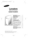
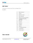
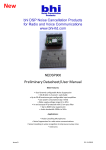
Single phase din rail meter SDM320C user manual SDM320C DIN rail single phase two wire energy meter with RS485 MODBUS RTU (Four modular) User Manual -----------1.1 1.2 1.3 1.4 1.5 1.6 1.7 1.8 1.9 1.10 Safety instruction Introductions Performance criteria Specifications Basic errors Dimension & material Installation Operating Protocol Technical support JIAXING EASTRON ELECTRONIC INSTRUMENTS CO., TLD. Address: No.1369, Chengnan Road, Nanhu, Jiaxing, Zhejiang, China Tel: +86-573-83698881 83698882 Fax: +86-573-83698883 Email: [email protected] Web: www.eastrongroup.com Single phase din rail meter SDM320C user manual 1.1 Safety instructions Information for Your Own Safety This manual does not contain all of the safety measures for operation of the equipment (module, device), because special operating conditions, and local code requirements or regulations may necessitate further measures. However, it does contain information which must be read for your personal safety and to avoid material damages. This information is highlighted by a warning triangle and is represented as follows, depending on the degree of potential danger. Warning This means that failure to observe the instruction can result in death, serious injury or considerable material damage. Caution This means hazard of electric shock and failure to take the necessary safety precautions will result in death, serious injury or considerable material damage. Qualified personnel Operation of the equipment (module, device) described in this manual may only be performed by qualified personnel. Qualified personnel in this manual means person who are authorized to commission, start up, ground and label devices, systems and circuits according to safety and Regulatory standards. Use for the intended purpose The equipment (device, module) may only be used for the application specified in the catalogue and the user manual, and only be connected with devices and components recommended and approved by Eastron. Proper handling The prerequisites for perfect, reliable operation of the product are proper transport, proper storage, installation and proper operation and maintenance. When operating electrical equipment, parts of this equipment automatically carry dangerous voltages. Improper handling can therefore result in serious injuries or material damage. Use only insulating tools. Do not connect while circuit is live (hot). Do not connect the meter to a 3 phase - 400VAC – network. Place the meter only in dry surroundings. Do not mount the meter in an explosive area or expose the meter to dust, mildew and insects. Make sure the wires are suitable for the maximum current of this meter. Make sure the AC wires are connected correctly before activating the current/voltage to the meter. Do not touch the meter connecting clamps directly with metal, blank wire and your bare hands as you may get electrical shock. Make sure the protection cover is placed after installation. Installation, maintenance and reparation should only be done by qualified personnel. Never break the seals and open the front cover as this might influence the function of the meter, and will cause no warranty. Do not drop, or allow strong physical impact on the meter as the high precisely components inside may be damaged. JIAXING EASTRON ELECTRONIC INSTRUMENTS CO., TLD. Address: No.1369, Chengnan Road, Nanhu, Jiaxing, Zhejiang, China Tel: +86-573-83698881 83698882 Fax: +86-573-83698883 Email: [email protected] Web: www.eastrongroup.com Single phase din rail meter SDM320C user manual 1.2 Introduction The Eastron SDM320C DIN rail single phase two wire energy meter with modbus protocol. Output is LCD displayed, based on kWh and the data can be transported by isolated RS485 . The meter is provided with a non-volatile memory system that ensures that the readings are not lost or altered when power off. The meter allows up to 100A direct load in single phase application. It is perfect measuring instruments for AMR system or Energy monitoring and control system. 1.3 Performance criteria Operating humidity Storage humidity Operating temperature Storage temperature International standard Accuracy class Protection against penetration of dust and water Insulating encased meter of protective class 1.4 Meter specifications Meter type Nominal voltage (Un) Operational voltage Insulation capabilities: - AC voltage withstand - Impulse voltage withstand Basic current (Ib) Maximum rated current (Imax) Operational current range Over current withstand Operational frequency range Internal power consumption Test output flash rate (RED LED) Pulse output rate (pins 5 & 6) reverse indicator (RED LED) Consumption indicator (RED LED) Communication indicator(GREEN LDE) Data communication port Data save 1.4.1 RS485 communication specifications Bus type protocol baud rate Address range Bus Loading Rage Parity Stop bit Data bits ≤ 85% ≤ 95% -20°C - +50°C -30°C - +70°C IEC 62053-21 0.5 or 1.0 IP51 Ⅱ SDM320C (LCD display) 230V AC 110V AC 0.7~1.3Un 2KV for 1 minute 6kV – 1.2µS waveform 1.5A/5A/10A 6A/60A/100A 0.4% Ib- Imax 30Imax for 0.01s 50~60Hz ±10% ≤2W / 10VA 12800/3200/1600imp/kWh 12800/3200/1600imp/kWh Current reverse Flashing at load running Flashing at communication running RS485 and far infrared The data can be stored more than 20 years RS485 MODBUS RTU 1200(default)/2400/4800/9600bps 1-247 user settable 64 meters per bus 1000M EVEN (default) /ODD/NONE 1 8 JIAXING EASTRON ELECTRONIC INSTRUMENTS CO., TLD. Address: No.1369, Chengnan Road, Nanhu, Jiaxing, Zhejiang, China Tel: +86-573-83698881 83698882 Fax: +86-573-83698883 Email: [email protected] Web: www.eastrongroup.com Single phase din rail meter SDM320C user manual 1.5 Infrared communication specifications Infrared wavelengths Baud rate Communication distance Communication angle 900- 1000nm 1200bps (default) 5m -15°~+15° 1.6 Dimensions 1.7 Installation CAUTION Turn off all the power before working on it. Always use a properly rated voltage sensing device to confirm that power is off. Installation should be performed by qualified personnel familiar with applicable codes and regulations. Use isolated tools to install the meter. Fuse or thermal cut-off or single-pole circuit breaker can’t be fitted on the supply line and not the neutral line. Don’t put your finger into the hole, because there is a screw inside. Please choose the available adapter which is supplied with the meter to suit the diameter of the cable. WARNING We recommend that the connecting wire which is used to connect the meter to the outside circuit should be sized according to local codes and regulations for the amp city of the circuit breaker or over current device used in the circuit. An external switch or a circuit-breaker should be installed on the inlet wire, which will be used as a disconnection device for the meter. And there it is recommended that the switch or circuit-breaker is JIAXING EASTRON ELECTRONIC INSTRUMENTS CO., TLD. Address: No.1369, Chengnan Road, Nanhu, Jiaxing, Zhejiang, China Tel: +86-573-83698881 83698882 Fax: +86-573-83698883 Email: [email protected] Web: www.eastrongroup.com Single phase din rail meter SDM320C user manual near the meter so that it is more convenience for the operator. The switch or circuit-breaker should comply with the specifications of the building electrical design and all local regulations. An external fuse or thermal cut-off which will be used as a over-current protection device for the meter must be installed on the supply side wire, and it is recommended that the over-current protection device is near the meter so that it is more convenience for the operator. The over-current protection device should comply with the specifications of the buildings electrical design and all local regulations. This meter can be installed indoor directly, or in a meter box which is waterproof outdoor, subject to local codes and regulations. To prevent tampering, secure the meter with a padlock or a similar device. The meter has to be installed against a wall which is fire resistant. The meter has to be installed in a good ventilated and dry place. The meter has to be installed in a protection box when placed in dangerous or dusty environment. The meter can be installed and used after being tested and sealed with a letter press printing. The meter can be installed on a 35mm DIN rail or direct on a meter board with screws. The meter should be installed in an available height so that it is easy to read. When the meter is installed in an area with frequent surges due to e.q. thunderstorms, welding machines, inverters etc, protect the meter with Surge Protection Devices. After installation, the meter must be sealed to prevent tampering. Connection of the wires should be done in accordance with the underneath connection diagram. 1.8 Operating Consumption indication There is a red LED which is used as indicating power consumption in the front panel of SDM-320C . When consumption happens, the LED will flash. The more quickly LED flashes, the more consumption there is. For this LED, the flash rate is indicated per kWh on the front panel Reverse indication There is a red LED which is used as indicating current reverse in the front panel Communication indication On the front panel of SDM320C,there is a COM.LED. When the data communicate between the far infrared port or RS485 port with outside equipment, the LED will blink. JIAXING EASTRON ELECTRONIC INSTRUMENTS CO., TLD. Address: No.1369, Chengnan Road, Nanhu, Jiaxing, Zhejiang, China Tel: +86-573-83698881 83698882 Fax: +86-573-83698883 Email: [email protected] Web: www.eastrongroup.com Single phase din rail meter SDM320C user manual Reading the meter The SDM-320C energy meter is equipped with 6+1 or 5+2 LCD display. which is used as recording consumption and can’t be reset to zero. The number system is based on units of 10. And unit is kWh. Another way through RS485 and PC software or HHU(hand held unit)unit can read power consumption Pulse output The SDM320C DIN rail energy meter is equipped with a pulse output which is fully separated from the inside circuit. That generates pulses in proportion to the measured energy for accuracy testing. The pulse output is a polarity dependant, passive transistor output requiring an external voltage source for correct operation. For this external voltage source, the voltage (Ui) should is 5-27V DC, and the maximum input current (Imax) is 27mA DC. To connect the impulse output, connect 5-27V DC to connector 6 (anode), and the signal wire (S) to connector 5 (cathode). The meter pulses is indicated on the front panel. Communication port SDM320C has equipped a far infrared port and a RS485 port, we can program the meter’s operation data or reading via these 2 ports. The communication protocol conforms MODBUS RTU protocol. Far infrared communication port The far infrared communication port is on the left of LCD screen. It is infrared wireless communication port. The TP800 hand-held programmer can directly communicate the data between the meter and this port. The data transmission speed is 1200bps (default) 9600bps(option). The communication distance is no more than 5m. Rs485 output RS485 communication port is between the meter terminal 8 and 7.It is a synchronization wire port. Installing a software in PC, via RS485 adapter. Connecting the terminal 8 and 7, PC can communicate with the meter immediately. 1.9 Protocol SDM320C has a RS485 port with Modbus RTU protocol. RS485 is a balanced line, half-duplex transmission system allowing transmission distances of up to 1 km. The following table summarizes the RS485 Standard: PARAMETER Mode of Operation Differential Number of Drivers and Receivers 32 Drivers 32 Receivers Maximum Cable Length 1200M Maximum Data Rate 10M baud Maximum Common Mode Voltage 12V to -7V Minimum Driver Output levels(loaded) ±1.5V Minimum Driver Output Levels(uploaded) ±1.5V Drive load Minimum 60 ohms Driver Output Short Circuit Current Limit 150mA to Gnd 250mA to 12V 250mA to -7V Minium Receiver Input Resistance 12Kohms Receiver Sensitivity ±200mV Further information relating to RS485 may be obtained from either the Eastron or the various RS485 JIAXING EASTRON ELECTRONIC INSTRUMENTS CO., TLD. Address: No.1369, Chengnan Road, Nanhu, Jiaxing, Zhejiang, China Tel: +86-573-83698881 83698882 Fax: +86-573-83698883 Email: [email protected] Web: www.eastrongroup.com Single phase din rail meter SDM320C user manual device manufacturers, for example Texas Instruments or Maxim Semiconductors. This list is not exhaustive. 1.9.1 Half Duplex Half duplex is a system in which one or more transmitters (talkers) can communicate with one or more receivers (listeners) with only one transmitter being active at any one time. For example, a “conversation” is started by asking a question, the person who has asked the question will then listen until he gets an answer or until he decides that the individual who was asked the question is not going to reply. In a 485 network the “master” will start the “conversation” with a “query” addressed to a specific “slave”, the “master” will then listen for the “slave’s” response. If the “slave” does not respond within a pre-defined period, (set by control software in the “master”), the “master” will abandon the “conversation”. 1.9.2 Connecting the Instruments If connecting an RS485 network to a PC use caution if contemplating the use of an RS232 to 485 converter together with a USB to RS485 adapter. Consider either an RS232 to RS485 converter, connected directly to a suitable RS232 jack on the PC, or use a USB to RS485 converter or, for desktop PCs a suitable plug in RS485 card. (Many 232:485 converters draw power from the RS232 socket. If using a USB to RS232 adapter, the adapter may not have enough power available to run the 232:485 converter.)Screened twisted pair cable should be used. For longer cable runs or noisier environments, use of a cable specifically designed for RS485 may be necessary to achieve optimum performance. All “A” terminals should be connected together using one conductor of the twisted pair cable, all “B” terminals should be connected together using the other conductor in the pair. The cable screen should be connected to the “Gnd” terminals. A Belden 9841 (Single pair) or 9842 (Two pair) or similar cable with a characteristic impedance of 120 ohms is recommended. The cable should be terminated at each end with a 120 ohm, quarter watt (or greater) resistor. Note: Diagram shows wiring topology only. Always follow terminal identification on Integra Digital meter product label. There must be no more than two wires connected to each terminal, this ensures that a “Daisy Chain or “straight line” configuration is used. A “Star” or a network with “Stubs (Tees)” is not recommended as reflections within the cable may result in data corruption. JIAXING EASTRON ELECTRONIC INSTRUMENTS CO., TLD. Address: No.1369, Chengnan Road, Nanhu, Jiaxing, Zhejiang, China Tel: +86-573-83698881 83698882 Fax: +86-573-83698883 Email: [email protected] Web: www.eastrongroup.com Single phase din rail meter SDM320C user manual 1.9.3 MODBUS Protocol General Information Communication on a MODBUS Protocol Network is initiated (started) by a “Master” sending a query to a “Slave”. The “Slave“, which is constantly monitoring the network for queries addressed to it, will respond by performing the requested action and sending a response back to the ”Master”. Only the “Master” can initiate a query. In the MODBUS Protocol the master can address individual slaves, or, using a special “Broadcast” address, can initiate a broadcast message to all slaves. The Integra Digital meter do not support the broadcast address. 1.9.3.1MODBUS Protocol Message Format There are two MODBUS Protocol serial transmission modes, ASCII and RTU.320c Meter support the support mode. The MODBUS Protocol defines the format for the master’s query and the slave’s response. The query contains the device (or broadcast) address, a function code defining the requested action, any data to be sent, and an error-checking field. The response contains fields confirming the action taken, any data to be returned, and an error-checking field. If an error occurred in receipt of the message then the message is ignored, if the slave is unable to perform the requested action, then it will construct an error message and send it as its response. The following example illustrates a request for two 16-bit Modbus Protocol Registers. JIAXING EASTRON ELECTRONIC INSTRUMENTS CO., TLD. Address: No.1369, Chengnan Road, Nanhu, Jiaxing, Zhejiang, China Tel: +86-573-83698881 83698882 Fax: +86-573-83698883 Email: [email protected] Web: www.eastrongroup.com Single phase din rail meter SDM320C user manual Slave Address: 8-bit value representing the slave being addressed (1 to 255), 0 is reserved for the broadcast address. The Integra Digital meters do not support the broadcast address. Function Code: 8-bit value telling the addressed slave what action is to be performed. (3, 4, 8 or 16 are valid for Integra Digital meter) Start Address (Hi): The top (most significant) eight bits of a 16-bit number specifying the start address of the data being requested. Start Address (Lo): The bottom (least significant) eight bits of a 16-bit number specifying the start address of the data being requested. As registers are used in pairs and start at zero, then this must be an even numberNumber of Points (Hi): The top (most significant) eight bits of a 16-bit number specifying the number of registers being requested. Number of Points (Lo): The bottom (least significant) eight bits of a 16-bit number specifying the number of registers being requested. As registers are used in pairs, then this must be an even number. Error Check (Lo): The bottom (least significant) eight bits of a 16-bit number representing the error check value. Error Check (Hi): The top (most significant) eight bits of a 16-bit number representing the error check value. Response The example illustrates the normal response to a request for two 16-bit Modbus Protocol Registers Slave Address: 8-bit value representing the address of slave that is responding. Function Code: 8-bit value which, when a copy of the function code in the query, indicates that the slave recognised the query and has responded. (See also Exception Response). Byte Count: 8-bit value indicating the number of data bytes contained within this response First Register (Hi)*: The top (most significant) eight bits of a 16-bit number representing the first register requested in the query. First Register (Lo)*: The bottom (least significant) eight bits of a 16-bit number representing the first register requested in the query. Second Register (Hi)*: The top (most significant) eight bits of a 16-bit number representing the second register requested in the query. Second Register (Lo)*: The bottom (least significant) eight bits of a 16-bit number representing the second register requested in the query. Error Check (Lo): The bottom (least significant) eight bits of a 16-bit number representing the error check value. Error Check (Hi): The top (most significant) eight bits of a 16-bit number representing the error check value. JIAXING EASTRON ELECTRONIC INSTRUMENTS CO., TLD. Address: No.1369, Chengnan Road, Nanhu, Jiaxing, Zhejiang, China Tel: +86-573-83698881 83698882 Fax: +86-573-83698883 Email: [email protected] Web: www.eastrongroup.com Single phase din rail meter SDM320C user manual 1.9.3.2How to communicate with SDM320C meter This part describes the register map for SDM-320C the function codes 0x03 to read register and 0x10 to write register. Address(hex) Length Parameters Access(R/W) Data Format Unit 0x011E 4 Total Energy R HEX Kwh/100 0x000F 2 Modbus ID W HEX 0xF800 2 Baud rate W HEX bps Example How to Read Total Energy Send:01 03 01 1E 00 02CRCL CRCH Receive:01 03 04 XX XX XX XX CRCL CRCH XX XX XX XX is Energy information,if XX XX XX XX=00 00 00 FF The 00 00 00 FF converted into decimal 255,So Total Energy is255/100=2.55Kwh How to change 01 to 15 First,15 converted into HEX 0x0f Send:01 10 00 0F 00 01 02 00 0F CRCLCRCH Receive:01 10 00 0F 00 01 CRCL CRCH How to change Baud rate Send:01 10 F8 00 00 01 02 XX XX CRCL CRCH XX XX=00 01 Baud rate 1200 XX XX=00 02 Baud rate 2400 XX XX=00 03 Baud rate 4800 XX XX=00 04 Baud rate 9600 Receive:01 10 F8 00 00 01 CRCL CRCH 1.10 Technical support Any questions please contact TEL 0086-573-83698881 FAX 0086-573-83698883 Email [email protected] Web www.eastrongroup.com JIAXING EASTRON ELECTRONIC INSTRUMENTS CO., TLD. Address: No.1369, Chengnan Road, Nanhu, Jiaxing, Zhejiang, China Tel: +86-573-83698881 83698882 Fax: +86-573-83698883 Email: [email protected] Web: www.eastrongroup.com