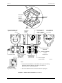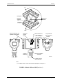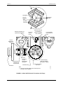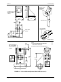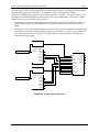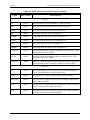
1
Siemens Energy & Automation USER'S MANUAL UM345-1 Rev: 3 April 2005 H XTC® Critical Pressure Transmitters Model 345 UM345-1 CONTENTS TABLE OF CONTENTS SECTION AND TITLE PAGE 1.0 INTRODUCTION ............................................................................................................................. 1-1 1.1 SECTION CONTENTS ................................................................................................................. 1-1 1.2 PRODUCT DESCRIPTION .......................................................................................................... 1-2 1.3 CONFIGURATION ....................................................................................................................... 1-7 1.4 INTERNATIONAL STANDARDS ORGANIZATION (ISO) SYMBOLS ................................. 1-9 1.5 PRODUCT SUPPORT................................................................................................................... 1-9 2.0 MODEL 275 UNIVERSAL HART COMMUNICATOR.............................................................. 2-1 2.1 INTRODUCTION.......................................................................................................................... 2-1 2.2 COMMUNICATOR CONNECTIONS ......................................................................................... 2-1 2.3 CONTROLS OVERVIEW ............................................................................................................ 2-4 2.3.1 Liquid Crystal Display ........................................................................................................... 2-4 2.3.2 Software-Defined Function Keys........................................................................................... 2-4 2.3.3 Action Keys............................................................................................................................ 2-6 2.3.4 Alphanumeric and Shift Keys ................................................................................................ 2-7 2.3.4.1 Rapid Selection of Menu Options.................................................................................. 2-7 2.3.4.2 Data Entry...................................................................................................................... 2-7 2.4 GETTING TO KNOW THE COMMUNICATOR........................................................................ 2-8 2.4.1 Display Icons.......................................................................................................................... 2-8 2.4.2 Menu Structure....................................................................................................................... 2-8 2.4.3 Reviewing Installed Devices.................................................................................................. 2-9 2.5 MAIN MENU .............................................................................................................................. 2-10 2.5.1 Offline Menu........................................................................................................................ 2-10 2.5.1.1 New Configuration ...................................................................................................... 2-11 2.5.1.2 Saved Configuration .................................................................................................... 2-14 2.5.2 Online Menu ........................................................................................................................ 2-16 2.5.3 Frequency Device Menu ...................................................................................................... 2-19 2.5.4 Utility Menu......................................................................................................................... 2-19 2.5.4.1 Configure Communicator ............................................................................................ 2-19 2.5.4.2 System Information...................................................................................................... 2-20 2.5.4.3 Listen for PC................................................................................................................ 2-20 2.5.4.4 Storage Location .......................................................................................................... 2-20 2.5.4.5 Simulation.................................................................................................................... 2-20 2.6 USING THE QUICK ACCESS KEY .......................................................................................... 2-21 2.6.1 Adding Quick Access Key Options ..................................................................................... 2-22 2.6.2 Deleting Quick Access Key Options.................................................................................... 2-23 3.0 COMMISSIONING AND BENCH TESTING............................................................................... 3-1 3.1 COMMISSIONING PROCEDURE............................................................................................... 3-1 3.1.1 Test Equipment Needed ......................................................................................................... 3-2 3.2 ESTABLISHING COMMUNICATION ....................................................................................... 3-3 3.3 TESTING THE TRANSMITTER.................................................................................................. 3-3 3.4 REVIEWING CONFIGURATION DATA ................................................................................... 3-4 3.5 CHECKING TRANSMITTER OUTPUT...................................................................................... 3-4 4.0 INSTALLATION .............................................................................................................................. 4-1 4.1 EQUIPMENT DELIVERY AND HANDLING ............................................................................ 4-1 4.1.1 Receipt of Shipment............................................................................................................... 4-1 4.1.2 Storage ................................................................................................................................... 4-2 4.2 ENVIRONMENTAL CONSIDERATIONS.................................................................................. 4-2 August 2000 i CONTENTS UM345-1 4.3 INSTALLATION CONSIDERATIONS ....................................................................................... 4-2 4.3.1 Mechanical............................................................................................................................. 4-2 4.3.2 Electrical ................................................................................................................................ 4-3 4.3.3 Impulse Piping for Models 345D, A, and G .......................................................................... 4-4 4.3.4 Transmitter Operating Mode and Network Type................................................................... 4-9 4.3.5 Power Supply Requirements................................................................................................ 4-14 4.3.5.1 Point-to-Point Network................................................................................................ 4-14 4.3.6 Cable Capacitance and Maximum Length ........................................................................... 4-15 4.3.6.1 Cable Capacitance........................................................................................................ 4-15 4.3.6.2 Maximum Cable Length Calculation........................................................................... 4-15 4.3.7 Network Junctions................................................................................................................ 4-16 4.3.8 Safety Barriers...................................................................................................................... 4-16 4.3.9 Connection of Miscellaneous Hardware .............................................................................. 4-17 4.3.10 Shielding and Grounding ................................................................................................... 4-17 4.4 MECHANICAL INSTALLATION, MODELS 345D, A, AND G.............................................. 4-18 4.4.1 Pipe Mounting, Models 345D, A, and G ............................................................................. 4-18 4.4.2 Flat Surface Mounting, Models 345D, A, and G ................................................................. 4-22 4.4.3 Direct Mounting to Process, Model 345D ........................................................................... 4-23 4.5 MECHANICAL INSTALLATION, MODEL 345F.................................................................... 4-24 4.6 MECHANICAL INSTALLATION, ALL MODELS .................................................................. 4-29 4.6.1 Smart Display Installation, Repositioning, and Removal .................................................... 4-29 4.6.2 Electrical Conduit and Cable Installation ............................................................................ 4-31 4.6.2.1 Conduit......................................................................................................................... 4-31 4.6.2.2 Cables .......................................................................................................................... 4-32 4.6.2.3 Access to Transmitter Terminal Compartment............................................................ 4-32 4.7 ELECTRICAL INSTALLATION ............................................................................................... 4-33 4.7.1 Loop Wiring......................................................................................................................... 4-33 4.7.2 Transient Suppressor Option................................................................................................ 4-34 4.8 HAZARDOUS AREA INSTALLATION ................................................................................... 4-35 5.0 POST-INSTALLATION CHECKOUT .......................................................................................... 5-1 5.1 EQUIPMENT REQUIRED............................................................................................................ 5-1 5.2 INSTALLATION REVIEW .......................................................................................................... 5-1 5.3 EQUIPMENT CONNECTION...................................................................................................... 5-1 5.4 VERIFICATION............................................................................................................................ 5-2 5.4.1 Communication Test .............................................................................................................. 5-2 5.4.2 Communications Error Check................................................................................................ 5-3 5.4.3 Verify Analog Output Signal ................................................................................................. 5-3 6.0 ON-LINE CONFIGURATION AND OPERATION ..................................................................... 6-1 6.1 ENABLING OR DISABLING CONFIGURATION..................................................................... 6-1 6.2 REMOTE CONFIGURATION AND OPERATION .................................................................... 6-1 6.2.1 Configuration ......................................................................................................................... 6-2 6.2.1.1 Write Protect and Transmitter Password ....................................................................... 6-2 6.2.1.2 Select a Function Block ................................................................................................. 6-3 6.2.1.3 Sensor Input Block......................................................................................................... 6-3 6.2.1.4 Operator Display Block ................................................................................................. 6-5 6.2.1.5 Transmitter ID................................................................................................................ 6-6 6.2.1.6 Autorecover or Latch ..................................................................................................... 6-7 6.2.1.7 Alarm Block................................................................................................................... 6-7 6.2.2 SEND and SAVE a Configuration......................................................................................... 6-8 6.2.3 Quick Access Key Functions ................................................................................................. 6-9 6.2.3.1 XMTR Variables............................................................................................................ 6-9 ii August 2000 UM345-1 CONTENTS 6.2.3.2 Status............................................................................................................................ 6-10 6.2.3.3 Range Xmtr.................................................................................................................. 6-11 6.3 LOCAL TRANSMITTER OPERATION .................................................................................... 6-11 6.3.1 Smart Display Functionality ................................................................................................ 6-12 6.4 LOCAL TRANSMITTER CONFIGURATION.......................................................................... 6-13 6.4.1 Set Local Zero...................................................................................................................... 6-13 6.4.2 Set Local Fullscale ............................................................................................................... 6-14 6.4.3 Adjust Local Damping ......................................................................................................... 6-14 7.0 CALIBRATION AND MAINTENANCE ....................................................................................... 7-1 7.1 CALIBRATION............................................................................................................................. 7-1 7.1.1 Equipment Required .............................................................................................................. 7-1 7.1.2 Zero Trim ............................................................................................................................... 7-3 7.1.2.1 Removing Zero Shift ..................................................................................................... 7-4 7.1.3 On-Line Zero Adjust.............................................................................................................. 7-5 7.1.4 Calibrate Digital-to-Analog Converter (DAC) ...................................................................... 7-6 7.2 PREVENTIVE MAINTENANCE ................................................................................................. 7-8 7.2.1 Tool and Equipment Requirements........................................................................................ 7-8 7.2.2 Transmitter Exterior Inspection ............................................................................................. 7-8 7.2.3 Transmitter Exterior Cleaning................................................................................................ 7-9 7.2.4 Transmitter Enclosure Interior Inspection ............................................................................. 7-9 7.2.5 Transmitter Calibration .......................................................................................................... 7-9 7.2.6 Impulse Piping ..................................................................................................................... 7-10 7.3 TROUBLESHOOTING ............................................................................................................... 7-10 7.3.1 Analog Output...................................................................................................................... 7-10 7.3.2 Digital Output (Communication) ......................................................................................... 7-12 7.3.3 Diagnosing a Defective Transmitter .................................................................................... 7-12 7.3.3.1 Additional Troubleshooting for Electronics Module Failure....................................... 7-13 7.3.3.2 Additional Troubleshooting for a Sensor Assembly.................................................... 7-13 7.4 ASSEMBLY REMOVAL AND REPLACEMENT .................................................................... 7-14 7.4.1 Replacing the Electronics Module ....................................................................................... 7-14 7.4.2 Sensor Assembly Removal and Replacement...................................................................... 7-15 7.4.3 Terminal Board Assembly Removal and Replacement ....................................................... 7-17 7.5 NON-FIELD-REPLACEABLE ITEMS ...................................................................................... 7-18 7.6 TRANSMITTER REPLACEMENT............................................................................................ 7-18 7.7 MAINTENANCE RECORDS ..................................................................................................... 7-19 7.8 RECOMMENDED SPARE AND REPLACEMENT PARTS .................................................... 7-19 7.9 SOFTWARE COMPATIBILITY ................................................................................................ 7-20 7.10 RETURN SHIPMENT............................................................................................................... 7-20 8.0 CIRCUIT DESCRIPTION ............................................................................................................... 8-1 8.1 SENSOR ASSEMBLY .................................................................................................................. 8-2 8.2 ELECTRONICS MODULE........................................................................................................... 8-2 8.3 THEORY OF OPERATION.......................................................................................................... 8-4 8.3.1 Pressure to Frequency Conversion......................................................................................... 8-4 8.3.2 Frequency to Digital Conversion ........................................................................................... 8-4 8.3.3 D/A Conversion and Current Signal Transmission (Outputs 1 and 2)................................... 8-4 8.3.4 Communication Format ......................................................................................................... 8-6 8.4 TRANSIENT SUPPRESSOR OPTION ........................................................................................ 8-6 9.0 MODEL DESIGNATIONS AND SPECIFICATIONS.................................................................. 9-1 9.1 MODEL DESIGNATIONS ........................................................................................................... 9-1 9.2 ACCESSORIES ............................................................................................................................. 9-8 August 2000 iii CONTENTS UM345-1 9.3 SPECIFICATIONS ........................................................................................................................ 9-8 9.3.1 Mechanical............................................................................................................................. 9-8 9.3.2 Performance and Functional Specifications......................................................................... 9-12 9.3.3 Two-Wire Cable................................................................................................................... 9-14 9.3.4 Environmental...................................................................................................................... 9-14 9.3.5 Safety and Hazardous Area Classifications ......................................................................... 9-16 9.3.5.1 CSA Hazardous Locations Precautions ....................................................................... 9-18 9.3.6 Special Conditions For Safe Use.......................................................................................... 9-18 10.0 GLOSSARY ................................................................................................................................... 10-1 A.0 APPENDIX A - FUNCTION BLOCKS ........................................................................................ A-1 A.1 WRITE PROTECT BLOCK .........................................................................................................A-1 A.2 SENSOR INPUT BLOCK ............................................................................................................A-1 A.3 OPERATOR DISPLAY BLOCK .................................................................................................A-3 A.4 TRANSMITTER ID BLOCK .......................................................................................................A-4 A.5 ALARM BLOCK ..........................................................................................................................A-5 A.6 OUTPUT BLOCK.........................................................................................................................A-6 B.0 APPENDIX B - HAZARDOUS AREA INSTALLATION ...........................................................B-1 C.0 TRANSMITTER CONFIGURATION DOCUMENTATION.................................................... C-1 D.0 APPENDIX D - ELEVATION AND SUPPRESSION CORRECTIONS................................... D-1 D.1 HOW ADJUSTMENT IS MADE .................................................................................................D-1 D.2 ELEVATION CALCULATION EXAMPLE ...............................................................................D-2 D.3 SUPPRESSION CALCULATION EXAMPLE............................................................................D-2 D.4 RECOMMENDED METHOD......................................................................................................D-3 E.0 APPENDIX E - CENELEC EEX D INSTALLATIONS...............................................................E-1 F.0 APPENDIX F - STATIC PRESSURE CORRECTION ................................................................F-1 G.0 SAFETY INSTRUMENTED SYSTEM ........................................................................................ G-1 G.1 REQUIREMENTS FOR TÜV CERTIFICATION .......................................................................G-3 G.1.1 General System Requirements ..............................................................................................G-3 G.1.2 Functional Requirements ......................................................................................................G-4 G.1.3 Environmental Requirements................................................................................................G-4 G.2 SAFETY AND FUNCTIONAL SAFETY....................................................................................G-4 G.2.1 Safety Accuracy Specifications.............................................................................................G-4 G.2.2 Other Considerations.............................................................................................................G-6 G.2.3 Safety Philosophy..................................................................................................................G-6 G.2.4 The Project Team ..................................................................................................................G-7 G.2.5 Safety Management...............................................................................................................G-8 G.2.6 SIS Documentation Requirements ........................................................................................G-8 G.3 THE SAFETY LIFE CYCLE........................................................................................................G-9 G.3.1 Safety Life Cycle Steps.........................................................................................................G-9 G.3.2 SIS Application Scope Requirements .................................................................................G-10 G.4 PROCESS DESIGN AND HAZARD ANALYSIS ....................................................................G-10 G.5 SAFETY INSTRUMENTED SYSTEM DESIGN .....................................................................G-10 G.5.1 Single Analog Sensors ........................................................................................................G-10 G.5.2 Dual Analog Sensors...........................................................................................................G-10 G.5.3 Triple Analog Sensors.........................................................................................................G-11 iv August 2000 UM345-1 CONTENTS G.6 INSTALLATION, COMMISSIONING, AND ACCEPTANCE TEST .....................................G-11 G.6.1 Installation...........................................................................................................................G-11 G.6.2 Commissioning ...................................................................................................................G-12 G.6.3 Acceptance Test ..................................................................................................................G-12 G.6.4 Activating Secure Mode......................................................................................................G-12 G.7 OPERATION AND MAINTENANCE PLANNING .................................................................G-12 G.7.1 On-line Configuration Editing ............................................................................................G-12 G.7.2 Proof Testing.......................................................................................................................G-12 G.7.3 Maintenance ........................................................................................................................G-13 G.8 OTHER CONSIDERATIONS ....................................................................................................G-13 G.8.1 Pre-Startup Acceptance Test (PSAT)..................................................................................G-13 G.8.2 Proof Testing.......................................................................................................................G-13 H.0 USING THE TRANSMITTER IN A GENERIC PLC SYSTEM ............................................... H-1 H.1 INTERPRETING THE INPUT SIGNAL .....................................................................................H-2 H.2 1OO2D VOTING OF ANALOG SIGNALS ................................................................................H-5 H.3 VOTE_1OO2D FUNCTION BLOCK BODY..............................................................................H-8 W.0 WARRANTY ................................................................................................................................. W-1 PARTS LIST PL345-1 AD34-4 XTC CONFIGURATION MAPS LIST OF ILLUSTRATIONS FIGURE AND TITLE PAGE 1-1 1-2 1-3 1-4 1-5 1-6 1-7 Model 345D Transmitter.................................................................................................................... 1-3 Models 345A and 345G ..................................................................................................................... 1-4 Model 345F Differential Transmitter with Flange ............................................................................. 1-5 Traditional Process Variable Measurement ....................................................................................... 1-6 Process Variable Measurement using QUADLOG............................................................................ 1-7 Optional Smart Display...................................................................................................................... 1-8 Terminal Board .................................................................................................................................. 1-8 2-1 2-2 2-3 2-4 2-5 2-6 Model 275 Universal HART Communicator ..................................................................................... 2-2 HART Communicator Connections to a Transmitter Loop ............................................................... 2-3 Communicator Display Icons............................................................................................................. 2-8 Offline Menu Tree............................................................................................................................ 2-11 Online Menu Tree for Model 345 Critical Transmitter.................................................................... 2-17 Generic Online Menu Tree............................................................................................................... 2-18 3-1 Bench Test Connections..................................................................................................................... 3-1 3-2 Field Test Connections....................................................................................................................... 3-2 4-1 4-2 4-3 4-4 4-5 4-6 4-7 Differential Flow Measurement Piping for Gas or Liquid ................................................................. 4-5 Differential Liquid Measurement Piping ........................................................................................... 4-6 Absolute or Gauge Pressure Measurement Piping............................................................................. 4-7 Steam Service, Below the Line Mounting ......................................................................................... 4-8 Open and Closed Tank Level Measurement, Flange Mounted Differential Transmitters ................. 4-9 Point-To-Point Network (Analog Mode) ......................................................................................... 4-10 Model 353/354 to Model 345 Connections (Analog Mode) ............................................................ 4-11 August 2000 v CONTENTS UM345-1 4-7a Procidia i|pac to Model 345 Connections....................................................................................... 4-12 4-8 APACS+ Critical Analog Module to Model 345 Connections ........................................................ 4-13 4-9 2" Pipe Mount Bracket, Model 345D............................................................................................... 4-20 4-10 2" Pipe Mount Bracket, Models 345A and G................................................................................. 4-21 4-11 Universal Mounting Bracket, Model 345D.................................................................................... 4-23 4-12 Universal Mounting Bracket, Models 345A and G........................................................................ 4-24 4-13 Flange Mounted Transmitter, Model 345F .................................................................................... 4-27 4-14 Smart Display Removal and Repositioning ................................................................................... 4-30 4-15 Conduit Drain and Explosion Proof Installations .......................................................................... 4-32 4-16 Conductor Terminations................................................................................................................. 4-34 5-1 Equipment Connection for System Checkout .................................................................................... 5-2 7-1 Bench Test Connections..................................................................................................................... 7-2 7-2 Field Test Connections....................................................................................................................... 7-2 8-1 Critical Transmitter Block Diagram................................................................................................... 8-1 8-2 Block Diagram, Electronics Module and Sensor Assembly .............................................................. 8-2 9-1 Dimensions, Model 345D Transmitter............................................................................................. 9-10 9-2 Dimensions, Models 345A and G .................................................................................................... 9-11 A-1 Function Block Arrangement in the Model 345 Transmitter ............................................................A-1 D-1 D-2 D-3 D-4 Elevated Span Example.....................................................................................................................D-1 Suppressed Span Example ................................................................................................................D-1 Elevated Calculation Example ..........................................................................................................D-2 Suppression Calculation Example.....................................................................................................D-2 G-1 Analog Sensor Architecture ............................................................................................................G-10 G-2 Dual Analog Sensor Architecture....................................................................................................G-11 H-1 H-2 H-3 H-4 Transmitter Signal Outputs ...............................................................................................................H-1 Transmitter Function Block for Floating Point Input........................................................................H-3 Transmitter Function Block for Integer Input ...................................................................................H-4 1oo2D Voting of 345 Inputs..............................................................................................................H-6 LIST OF TABLES TABLE AND TITLE PAGE 1-1 Model Number vs. Figure References................................................................................................ 1-2 1-2 ISO/IEC Symbols............................................................................................................................... 1-9 1-3 TIC Contact Information.................................................................................................................. 1-10 2-1 Function Keys with Their Labels and Actions Performed ................................................................. 2-5 2-2 Moore Device Descriptions.............................................................................................................. 2-10 4-1 Flange and Extension Dimensions ................................................................................................... 4-28 6-1 Configuration Jumper Positioning ..................................................................................................... 6-1 7-1 Error Codes ...................................................................................................................................... 7-13 vi August 2000 UM345-1 9-1 9-2 9-3 9-4 9-5 9-6 9-7 CONTENTS Model 345D, Model Designation .......................................................................................................9-2 Model 345A, Model Designation .......................................................................................................9-3 Model 345G, Model Designation .......................................................................................................9-4 Model 345F, Model Designation........................................................................................................9-5 Model 345 Sterling High Performance...............................................................................................9-6 Model 345 with Tantalum Diaphragms ..............................................................................................9-7 Model 345 Accessories.......................................................................................................................9-8 G-1 Detailed Fault Checking ................................................................................................................... G-5 G-2 Safety Integrity Levels...................................................................................................................... G-7 H-1 Current Output for the 345................................................................................................................ H-1 H-2 Results of 1oo2D Voting 345 Input Signals ..................................................................................... H-5 H-3 VOTE_1002D Function Block Inputs and Outputs.......................................................................... H-7 Changes for Rev. 3, August 2000 Significant changes to UM345-1 are listed in the following table. Section Table of Contents 1. Introduction 7. Calibration and Maintenance Appendix G Appendix H Warranty Change Updated Product Support subsection updated. Section 7.3.3 updated. Updated. New. Updated. Changes for Rev. 3, March 2005 Significant changes to UM345-1 are listed in the following table. Section Table of Contents 1. Introduction Warranty Change Updated Product Support subsection updated. Updated. Changes for Rev. 3, April 2005 Significant changes to UM345-1 are listed in the following table. Section 1. Introduction Change Product Support subsection updated. August 2000 vii CONTENTS UM345-1 XTC, Procidia, APACS, and QUADLOG are trademarks of Siemens Energy & Automation, Inc. Other trademarks are the property of their respective owners. Siemens Energy & Automation, Inc. assumes no liability for errors or omissions in this document or for the application and use of information included in this document. The information herein is subject to change without notice. Procedures in this document have been reviewed for compliance with applicable approval agency requirements and are considered sound practice. Neither Siemens Energy & Automation, Inc. nor these agencies is responsible for repairs made by the user. viii August 2000 UM345-1 INTRODUCTION 1.0 INTRODUCTION This user’s manual is for XTC Model 345 Critical Pressure Transmitters. All information needed to bench test, install, configure, calibrate, and service a transmitter is included in this user’s manual. IMPORTANT Save this user’s manual for installing, configuring, operating, and servicing a transmitter. 1.1 SECTION CONTENTS Ten sections and seven appendices make up this manual. A brief description of each section follows. Section 1, INTRODUCTION, describes each section in this manual and provides a brief description of the Model 345 Critical Pressure Transmitter. Section 2, MODEL 275 UNIVERSAL HART COMMUNICATOR, describes use of the HART Communicator to test, configure, and calibrate a transmitter. Section 3, COMMISSIONING AND BENCH TESTING, provides procedures to perform a bench test of the transmitter to ensure proper operation of all functions. Start-up configuration is described here. If desired, go to Section 6 to perform a complete configuration. The calibration procedure in Section 7 can be performed following configuration if the mounting position will induce a zero shift. Section 4, INSTALLATION, furnishes specific information for mechanical and electrical installation. Section 5, POST-INSTALLATION CHECKOUT, describes how to confirm that the transmitter has been installed correctly. Section 6, ON-LINE CONFIGURATION AND OPERATION, describes remote configuration using the Model 275 and operation and local configuration using the magnetic switches. Section 7, CALIBRATION AND MAINTENANCE, provides calibration procedures for analog and digital modes and a zeroing procedure for mounting position. It also furnishes preventive maintenance, troubleshooting, and assembly replacement procedures. A spare and replacement parts list is provided at the back of this manual. Section 8, CIRCUIT DESCRIPTION, contains an assembly-level circuit description to support transmitter servicing. Section 9, MODEL DESIGNATIONS AND SPECIFICATIONS, furnishes tables describing transmitter model numbers. It also contains mechanical, functional, performance, and environmental specifications. Hazardous area certifications are also listed. Section 10, GLOSSARY, contains definitions of various transmitter and safety related terms. APPENDIX A, FUNCTION BLOCKS, describes transmitter function blocks and the parameters available. August 2000 1-1 INTRODUCTION UM345-1 APPENDIX B, HAZARDOUS AREA INSTALLATION, contains an installation drawing and information needed for barrier selection. APPENDIX C, TRANSMITTER CONFIGURATION DOCUMENTATION, provides a form for entering application-specific configuration data. APPENDIX D, ELEVATION AND SUPPRESSION CORRECTIONS, explains how to perform elevation and suppression calculations for certain liquid level gauging applications. APPENDIX E, CENELEC EEX D INSTALLATIONS, details proof testing procedures. APPENDIX F, STATIC PRESSURE CORRECTION, has an example of correction for static pressure. APPENDIX G, SAFETY INSTRUMENTED SYSTEMS and APPENDIX H, USING THE TRANSMITTER IN A GENERIC PLC SYSTEM, includes expansive information on SIS systems for critical process control. WARRANTY contains the product warranty statements and information concerning servicing of the product during the warranty period. PARTS LIST has exploded views of the four basic pressure transmitter models and a list of on-hand spare parts and field-replaceable parts. 1.2 PRODUCT DESCRIPTION Model 345 transmitters are part of the Siemens Moore XTC line of smart pressure and temperature field devices. They provide safe, reliable, accurate, stable, and cost-effective measurement of differential, absolute, and gauge pressures. Pressure sensor style influences a Model 345’s physical dimensions and mechanical installation. Note that a sensor style can involve one or more pressure measurement methods (i.e., differential, absolute, and gauge), as shown in Table 1-1. TABLE 1-1 Model Numbers vs. Figure References MODELS PRESSURE SENSOR REFER TO Model 345D, all Differential Figures 1-1, 4-10, 4-12, and 9-1 Model 345A Absolute, with tantalum diaphragm Model 345G Gauge, with tantalum diaphragm Model 345A Absolute Model 345G Gauge Model 345F Differential, flanged level Figures 1-2, 4-11, 4-13, and 9-2 Figures 1-3 and 4-13 Differential, flanged level, with extension 1-2 August 2000 UM345-1 INTRODUCTION 120º Nameplate Enclosure Rotation Magnetic Switches: Zero Damping Full Scale 120º Electronics Module and Optional Smart Display Loop Terminals and Isolated Tie Point Electrical Entrance, 1/2-14 NPT or M20 X 1.5 Tapped Hole, 2 Places Enclosure Ground Screw + _ TIE End Cap H Vent/Drain Plug Process Connection Block, 1/2 NPT Tapped Hole (See Note 1) Enclosure Rotation Set Screw Process Connection 1/4 NPT Tapped Hole Embossed Arrow Indicates High Pressure Port 7/16-20 Tapped Hole, 8 Places AG00205b Notes: Vent/Drain Plug (Side Vent Options Top, Bottom, or Both) 1. Process Connection Blocks can be rotated 180º to give the following connection centers: 2.00 (50.1), 2.13 (54.1), or 2.25 (57.2). Dimensions are in inches (millimeters). 2. Also shows Models 345A and 345G with tantalum diaphragms. FIGURE 1-1 Model 345D Transmitter (See Note 2) August 2000 1-3 INTRODUCTION UM345-1 120º Nameplate Enclosure Rotation Magnetic Switches: Zero Damping Full Scale 120º Electronics Module and Optional Smart Display Enclosure Ground Screw Electrical Entrance, 1/2-14 NPT or M20 X 1.5 Tapped Hole, 2 Places Loop Terminals and Isolated Tie Point _ + TIE Capsule Assembly Enclosure Rotation Set Screw AG00206b 1/2 NPT Process Inlet Connection Note: 1. For a Model 345A or 345G with tantalum diaphragms, see Figure 1-1. FIGURE 1-2 Models 345A and 345G (See Note 1) 1-4 August 2000 UM345-1 INTRODUCTION 120º Nameplate Enclosure Rotation Magnetic Switches: Zero Damping Full Scale 120º Electronics Module and Optional Smart Display Enclosure Ground Screw Electronics Module 1/2-14 NPT or M20 X 1.5 Tapped Hole, 2 Places 7/16-20 Tapped Hole, 4 Places Loop Terminals and Isolated Tie Point _ + TIE H Extension Vent/Drain Plug Vent/Drain Plug (Side Vent Options Top, Bottom, or Both) Enclosure Rotation Set Screw Note: 1. A Process Connection Block with 1/2 NPT process connection can be installed. AG00222b Embossed Arrow Indicates High Pressure Port Process Connection 1/4 NPT Tapped Hole, See Note 1 FIGURE 1-3 Model 345F Differential Transmitter with Flange August 2000 1-5 INTRODUCTION UM345-1 Each transmitter is a microprocessor-based, self-contained pressure-to-current transducer. The heart of the transmitter is the MycroSENSOR™. Developed and patented by Siemens Moore, the MycroSENSOR is a silicon, dual-capacitance pressure sensor assembly. It generates a direct digital output signal that is proportional to input pressure. The direct digital output in conjunction with the microprocessor provides Direct Digital Processing (DDP™). DDP provides advanced processing and compensation for varying ambient temperature and static pressure. This yields improved performance, stability, and reliability compared to conventional analog transmitters. Although signal processing is digital, the transmitter is always configured to operate in an analog mode. The transmitter is connected to a controller, recorder, or other field device. A loop known as a Point-toPoint network interconnects the instruments. Figure 1-4 shows a traditional application. 2 Wire 4-20 mA 2 Wire 4-20 mA AG00207b Digital Controller I/P Model 773 Model 345D Model 353 Flow FIGURE 1-4 Traditional Process Variable Measurement Figure 1-5 shows an application using a Model 345 with a QUADLOG safety system. The transmitter provides a current output dependent upon flow to the SAM/CAM Marshalled Termination Panel. The termination panel is connected to the Critical Analog Module through the Interconnect I/O Cable. The Critical Control Module reads the CAM’s data and provides an output to the Analog Output Module. Module output is routed through an Interconnect I/O Cable to this module’s termination panel and then to an I/P module connected to the valve. The Model 345 can also be used with the APACS HART Fieldbus Module and other I/O modules offered by Siemens Moore. 1-6 August 2000 UM345-1 INTRODUCTION APACS+ MODULRAC or SIXRAC Critical Control Module C I I C / / M O O Critical Analog Module (CAM) and Marshalled Termination Panel AG00208c Model 345D Critical Transmitter I I I I I I I / / / / / / / O O O O O O O Interconnect I/O Cables 2-Wire Twisted Pair, Shielded Cable, 4-20 mA Enhanced or Standard Analog Module and Marshalled Termination Panel I/P Model 773 Flow FIGURE 1-5 Process Variable Measurement Using QUADLOG The HART® (Highway Addressable Remote Transducer) protocol is used for communication between the transmitter and a HART Communicator, a personal computer running configuration software, or another remote device. This is done by superimposing the HART digital signal on the analog current. HART communications is used to transfer a new or edited configuration, remotely monitor the process variable, and service a transmitter. The transmitter can be equipped with an optional Smart Display™ (Figure 1-6) to permit local viewing of output variables and to make local configuration easier. Connection to the loop is made using a terminal board with three screw terminals (Figure 1-7), which is located on the opposite end of the transmitter enclosure from the Smart Display. The transmitters have an intrinsically safe, explosion proof, NEMA 4x (IP67/68), field mountable, hardened enclosure. Electrical conduit connections are ½ NPT or M20. All process wetted materials are 316 stainless steel or better. The flush-mount process connection of the Model 340F is compatible with standard ANSI and metric flange sizes for tanks and pipes. 1.3 CONFIGURATION The transmitter must be configured before use. Each transmitter is shipped with either a default configuration or, if specified at time of order, a custom configuration defined by the user. The user may need to edit the default configuration before the transmitter is used in a loop. Unauthorized access to a transmitter configuration can be limited to increase system security. A Configuration Jumper is provided to enable or disable both local and remote configuration. Remote configuration has additional security. Each transmitter can be assigned an eight-character password. This password must then be entered before configuration changes are allowed. Local configuration, when enabled by setting the Configuration Jumper, is accomplished with the magnetic screwdriver supplied with the transmitter. Zero, full scale, and damping can be set at the August 2000 1-7 INTRODUCTION UM345-1 locations shown in Figure 1-1. Remote configuration, when enabled by setting the Configuration Jumper and entering the password, is performed using a Model 275 HART Communicator that has the Siemens Moore Model 345 Device Description firmware (see Table 2-2). A Model 275 without this Device Description can still access the transmitter but only as a generic transmitter which may limit configuration and monitoring options. Device Descriptions are available from Siemens Moore. Shown with Enclosure Cap Removed PV PB % ENG SP AG00209c FIGURE 1-6 Optional Smart Display HART Communicator Connections X03030S2 Shown with Enclosure Cap Removed Loop (+) and (-) Screw Terminals on Terminal Board or Transient Suppression Terminal Board _ + TIE Insulating Cover TIE Terminal - Use as a floating tie point (splice). It is isolated from the Transmitter circuitry and the enclosure. FIGURE 1-7 Terminal Board 1-8 August 2000 UM345-1 INTRODUCTION 1.4 INTERNATIONAL STANDARDS ORGANIZATION (ISO) SYMBOLS Refer to Table 1-2 for an explanation of ISO and IEC symbols that, when appropriate, are prominently displayed on the surfaces of the hardware. The symbols are also used in instructions to denote CAUTION and WARNING notes. TABLE 1-2 ISO/IEC Symbols SYMBOL PUBLICATION DESCRIPTION ISO 3864, No. B.3.6 WARNING: Risk of Electric Shock. The symbol is prominently displayed on the surfaces of hardware. When used in an instruction, text accompanies the symbol that identifies something that can be dangerous and possibly life threatening to personnel. For example: WARNING: Risk of electric shock. Remove power from all involved wires before making connections to the Marshalled Termination Assembly. ISO 3864, No. B.3.1 CAUTION: Refer to accompanying Installation and Service Instruction. The symbol is prominently displayed on the surfaces of hardware. When used in an instruction, text accompanies the symbol that identifies something that can damage equipment or cause a control problem with a process. For example: CAUTION: The safety system should not be operated with forced I/O. IEC 417, No. 5019 PROTECTIVE CONDUCTOR TERMINAL Symbol is prominently displayed on the surfaces of hardware. Background Color=Yellow Symbol Color = Black Outline Color = Black Background Color=Yellow Symbol Color = Black Outline Color = Black Background Color = White Symbol Color = Black Outline Color = Black 1.5 PRODUCT SUPPORT This section provides the Internet site addresses, e-mail addresses, telephone numbers, and related information for customers to access Siemens product support. When contacting Siemens for support: • • Please have complete product information at hand: • For hardware, this information is provided on the product nameplate (part number or model number, serial number, and/or version). • For most software, this information is given in the Help > About screen. If there is a problem with product operation: • August 2000 Is the problem intermittent or repeatable? What symptoms have been observed? 1-9 INTRODUCTION UM345-1 • What steps, configuration changes, loop modifications, etc. were performed before the problem occurred? • What status messages, error messages, or LED indications are displayed? • What troubleshooting steps have been performed? • Is the installation environment (e.g. temperature, humidity) within the product’s specified operating parameters? For software, does the PC meet or exceed the minimum requirements (e.g. processor, memory, operating system)? • A copy of the product Service Instruction, User’s Manual, or other technical literature should be at hand. The Siemens public Internet site (see the table) has current revisions of technical literature, in Portable Document Format, for downloading. • To send an instrument to Siemens for repair, request a Return Material Authorization (RMA). IMPORTANT An instrument must be thoroughly cleaned (decontaminated) to remove any process materials, hazardous materials, or blood born pathogens prior to return for repair. Read and complete the Siemens RMA form(s). TABLE 1.1 Contact Information Telephone NORTH AMERICA Fax E-mail Hours of Operation Public Internet Site Repair Service +1 800 569 2132, option 2 for Siemens-Moore brand instruments +1 215 283 6358 [email protected] 8 a.m. to 6 p.m. eastern time Monday – Friday (except holidays) www.sea.siemens.com/ia +1 215 646 7400 extension 3187 Outside of North America see the Siemens web site at www.sea.siemens.com/ia; locate “Customer Support Process Instrumentation” and click the Contact Tech Support link to access the Global Support link. 1-10 August 2000 UM345-1 MODEL 275 UNIVERSAL HART COMMUNICATOR 2.0 MODEL 275 UNIVERSAL HART COMMUNICATOR The Model 275 Universal HART Communicator is a handheld interface that provides a common communication link to XTC 345 series transmitters and other HART-compatible instruments. This section describes HART Communicator connections, liquid crystal display, keypad, and on-line and off-line menus. It also provides overviews of some of the Communicator’s functions. The Communicator is shown in Figure 2-1. For information about the Communicator’s battery pack, Memory Module, Data Pack, and maintenance procedures, refer to the manual supplied with the Communicator. 2.1 INTRODUCTION The HART Communicator interfaces with a transmitter or other HART device using a 4-20 mA loop, provided a minimum load resistance of 250Ω is present between the Communicator and the power supply. The Communicator uses Bell 202 frequency-shift keying (FSK) in which high-frequency digital signals are imposed on a standard 4-20 mA transmitter loop. Since the loop net energy is unchanged, HART communication does not disturb the 4-20 mA signal. The Communicator can be used in hazardous and non-hazardous locations. WARNING An explosion can cause death or serious injury. Before connecting the Communicator in an explosive atmosphere, be sure the instruments in the loop are installed in accordance with intrinsically safe or non-incendive field wiring practices. See the Communicator’s nameplate and manual for certifications and approvals before connecting. 2.2 COMMUNICATOR CONNECTIONS The Communicator can interface with a transmitter from the control room, the instrument site, or any wiring termination point in the loop. Connections are made through loop connectors on the Communicator’s connection panel (Figure 2-1). The connection panel also may have a jack for the optional NiCad recharger, and it has a serial port for a future connection to a personal computer (PC). To interface with a transmitter or other HART device, connect the HART Communicator in parallel with the instrument or load resistor. The connections are nonpolar. For intrinsically safe FM and CSA wiring connections, see the manual supplied with the Communicator. WARNING An explosion can result in death or serious injury. Before making connections to the serial port or NiCad recharger jack in an explosive atmosphere, check the Communicator’s nameplate and manual for approvals. August 2000 2-1 MODEL 275 HART COMMUNICATOR UM345-1 Connection Panel Loop Connections, Non-Polar Serial Port NiCad Recharger Jack, Optional X03032S0 LCD F1 F2 F3 F4 Function Keys, Software Defined HART Communicator Communicator Nameplate On Back - See nameplate for certifications and approvals before connecting in a hazardous location. Communicator Model Number and Serial Number On Back Note: Keypad number sequence may be different from that shown. I Action Keys On/Off (I/O) Up Arrow Quick Access Key (>>>) Previous Menu (Back, left arrow) Down Arrow Select (Forward, right arrow) O ABC DEF 1 2 3 JKL MNO PQR 4 5 6 STU VWX YZ/ 7 8 #%& 0 < Alphanumeric Keys 9 > . GHI * :+ _ Shift Keys - Use to select alphabetic and other characters above a number, period or dash. FIGURE 2-1 Model 275 Universal HART Communicator 2-2 August 2000 UM345-1 MODEL 275 UNIVERSAL HART COMMUNICATOR Figure 2-2 illustrates typical wiring connection between the HART Communicator and a loop with a transmitter or other HART-compatible device on a loop. The Communicator is quickly connected into a transmitter loop. Non-Hazardous Location Range Resistor 250, typical Input Module, Controller or Other 1-5 Vdc Device; See Note 2 Circuit Junction AG00223a Current Sense Resistor 250 to 1100; See Note 3 Hazardous Location + Transmitter Terminals _ _ + TIE See Note 4 I I O O I O See Note 1 See Note 1 I O Notes: 1. HART Communicator Connections: Non-hazardous location - Connect as shown above. Hazardous location - Refer to Communicator nameplate and the Manual supplied with the Communicator for certifications and approvals before connecting. The HART Communicator is a non-polar device. 2. The System Power Supply may be part of the host input device or a separate device. 3. Network resistance equals the sum of the barrier resistances and the current sense resistor. Minimum value 250 Ohms; maximum value 1100 Ohms. 4. Supply and return barriers shown. Interconnect all cable shields and ground only at the barriers. FIGURE 2-2 HART Communicator Connections to a Transmitter Loop August 2000 2-3 MODEL 275 HART COMMUNICATOR UM345-1 A 40" (1 m) cable with a dual banana plug on one end and two mini-grabber plugs on the other is provided. The dual banana plug is inserted into the top of the Communicator. The mini-grabber clips are connected to lugs in the transmitter’s terminal board compartment or to the loop’s current sense resistance, usually at a receiving instrument (see Note below). NOTE The HART protocol requires a network (loop) resistance between 250Ω and 1100Ω to support communications. See Section 4.3.5 to determine resistance value and loop supply voltage. 2.3 CONTROLS OVERVIEW As shown in Figure 2-1, the front of the HART Communicator has five major functional areas: liquid crystal display (LCD), function keys, action keys, alphanumeric keys, and shift keys. The next five sections describe how each of these functional areas is used to enter commands and display data. 2.3.1 Liquid Crystal Display The liquid crystal display (LCD) is an 8-line by 21-character display that provides communication between the user and a connected device. When the HART Communicator is connected to a transmitter or other HART-compatible device, the top line of the Online menu displays the model name of the device and its tag. A typical display is shown below: MPCO 345A:PT100 Online 1->Loop Override 2 Calibrate/Test 3 Configure Xmtr 4 Setup Done HELP |SAVE ç❚ The bottom line of each menu is reserved for dynamic labels for the software-defined function keys, F1F4, which are found directly below the display. More information on software-defined function keys is given in the next section. 2.3.2 Software-Defined Function Keys The four software-defined function keys (softkeys), located below the LCD and marked F1 through F4, are used to perform software functions as indicated by the dynamic labels. Pressing the function key immediately beneath a label activates the displayed function. The label appearing above a function key indicates the function of that key for the current menu. For example, in menus providing access to on-line help, the HELP label appears above the F1 key. In menus providing access to the Online menu, the HOME label appears above the F3 key. Table 2-1 lists these labels and describes what happens when each function key is pressed. 2-4 August 2000 UM345-1 MODEL 275 UNIVERSAL HART COMMUNICATOR TABLE 2-1 Function Keys with Their Labels and Actions Performed F1 F2 F3 F4 HELP ON/OFF ABORT OK access on-line help activate or deactivate a bit-enumerated binary variable terminate current task acknowledge information on the LCD RETRY DEL ESC ENTER try to reestablish communication delete current character or Quick Access Key menu item leave a value unchanged accept user-entered data EXIT SEND QUIT EXIT leave the current menu send configuration data to device terminate session because of a communication error Leave the current menu YES PGUP PGDN NO answer to yes/no question move up one help screen move down one help screen answer to yes/no question ALL PREV NEXT ONE include current Quick Access Key item on Quick Access Key menu for all devices go to previous message in a list of messages go to next message in a list of messages include Quick Access Key item for one device NEXT SAVE HOME go to the next variable in off-line edit save information to Communicator go the top menu in the device description FILTR MARK BACK open customization menu to sort configurations toggle marked variable in configuration to be sent to a field device go back to the menu from which HOME was pressed XPAND EDIT opens detailed configuration information edit a variable value CMPRS ADD closes detailed configuration information add current item to Quick Access Key menu August 2000 2-5 MODEL 275 HART COMMUNICATOR UM345-1 2.3.3 Action Keys Directly beneath the LCD and software-defined function keys are six blue, white, and black action keys. Each has a specific function as described below: I O ON/OFF KEY – Use to power-up the Communicator. When the Communicator is turned on, it automatically searches for a HART-compatible device on the 4-20 mA loop. If no device is found, the Communicator displays the Main menu: HART Communicator 1->Offline 2 Online 3 Frequency device 4 Utility If a HART-compatible device is found, the Communicator displays the Online menu: MPCO 345A:PT100 Online 1->Loop Override 2 Calibrate/Test 3 Configure Xmtr 4 Setup Done HELP |SAVE ç❚ UP ARROW KEY – Use to move the cursor up through a menu or list of options or to scroll through lists of available characters when editing fields that accept both alpha and numeric data. DOWN ARROW KEY – Use to move the cursor through a menu or a list of options or to scroll through lists of available characters when editing fields that accept alpha and numeric data. LEFT ARROW/PREVIOUS MENU KEY – Use to move the cursor to the left or back to the previous menu. RIGHT ARROW/SELECT KEY – Use to move the cursor to the right or to select a menu option. QUICK ACCESS KEY (HOT KEY) – When the Communicator is on and connected to a HART-compatible device, press the Quick Access Key to display the Quick Access Key menu of user-defined options. When the Communicator is off and the Quick Access Key is pressed, the Communicator powers-up and displays the Quick Access Key menu. See Section 2.6 for more information on using the Quick Access Key. IMPORTANT 2-6 August 2000 UM345-1 MODEL 275 UNIVERSAL HART COMMUNICATOR When performing certain operations, the message “OFF KEY DISABLED” indicates that the Communicator cannot be turned off. This feature helps prevent accidental shutoff of the Communicator while the output of a device is fixed or a device variable is being edited. 2.3.4 Alphanumeric and Shift Keys The alphanumeric keys perform two functions: 1) rapid selection of menu options and 2) data entry. The shift keys located below the alphanumeric keys on the keypad are used during data entry to select from among the characters available above each number. 2.3.4.1 Rapid Selection of Menu Options From any menu, use the keypad to select available options in two ways. First, use the UP or DOWN arrow keys, followed by the RIGHT ARROW/SELECT key, to access available options displayed on the LCD. As an alternative, use the rapid select feature. Simply press the number on the alphanumeric keypad that corresponds to the desired menu option. For example, to quickly access the Utility menu from the Main menu, simply press “4” on the keypad. 2.3.4.2 Data Entry Some menus require data entry. Use the alphanumeric and shift keys to enter all alphanumeric information into the HART Communicator. Pressing an alphanumeric key alone while editing causes the large character in the center of the key (number 0-9, decimal point, or dash) to be entered. Pressing and releasing a shift key activates shift and causes the appropriate arrow icon (ã, á, or ä) to appear in the upper right-hand corner of the LCD. When shift is activated, the indicated alpha characters or symbols are entered when the keypad is used. Example To enter a number, such as “7,” simply press the number key. To enter one of the small characters appearing above the large numeral (i.e., a letter, space, or mathematical symbol), first press and release the corresponding shift key at the bottom of the keypad, then press the desired alphanumeric key. To enter the letter “E,” press and release the middle shift key, then press the number “2” key. To deactivate a shift key without entering a letter, space, or mathematical symbol, simply press that shift key again. August 2000 2-7 MODEL 275 HART COMMUNICATOR UM345-1 2.4 GETTING TO KNOW THE COMMUNICATOR The HART Communicator operates in either of two modes: on-line or off-line. Off-line operation is used to create or edit a configuration that can then be downloaded to a HART device, such as the Model 345. On-line operation is used to download a configuration to a HART device, upload a configuration, edit HART device operating parameters, and monitor process values. For off-line operation, the Communicator need not be connected to a HART device. On-line operation requires a connection to a HART device. The menu that appears first when the Communicator is turned on depends on the mode. When the Communicator is powered-up in off-line mode, the first menu displayed is the Main menu. When the Communicator is powered-up in on-line mode, the first menu displayed is the Online menu. To work offline when connected to the loop, access the Main menu from the Online menu by pressing the LEFT ARROW/PREVIOUS MENU key. 2.4.1 Display Icons Several different symbols (icons) appear on the LCD to show the state of the Communicator and provide visible response to actions of the user. Figure 2-3 shows the display icons and how they relate to keypad functions. HART Communication ( indicates connected device is configured in the burst mode) HART Communicator Access Additional Menu Items Device Info 2 Dev Type 3 Dev ID 4 Tag 5 MM/DD/YY 6 Write Protect Low Battery 0 10/10/10 Yes Access Previous Menu X03034S0 FIGURE 2-3 Communicator Display Icons 2.4.2 Menu Structure The HART Communicator uses a hierarchical menu structure. That is, high-level menus are accessed first, and they provide access to lower-level menus. This structure groups related functions together and minimizes the number of options displayed at once. 2-8 August 2000 UM345-1 MODEL 275 UNIVERSAL HART COMMUNICATOR To learn how the menu structure works, perform the following actions: 1. With the Communicator off-line (not attached to any devices), press the ON/OFF key to turn the Communicator on. It displays the Main menu, with the cursor (->) positioned at “1 Offline.” 2. Access the Utility menu by pressing the DOWN arrow key three times, then pressing the RIGHT ARROW/SELECT key. The display changes to show the Utility menu. 3. Access the Configure Communicator menu from the Utility menu by pressing the RIGHT ARROW/SELECT key. The display changes to show the Configure Communicator menu. 4. Access the Contrast menu by pressing the DOWN arrow once, then pressing the RIGHT ARROW/SELECT key. The display shows a message explaining how to adjust the LCD contrast. 5. Press ESC (F3) to return to the Configure Communicator menu. 6. Press the LEFT ARROW/PREVIOUS MENU key two times to return to the Main menu. 7. Press the ON/OFF key to turn the Communicator off. 2.4.3 Reviewing Installed Devices For the HART Communicator to recognize a HART-compatible device, it must have a description for that device installed. The HART Communicator is supplied from the factory with descriptions for Model 345 Transmitters and other HART-compatible devices from leading manufacturers. In addition, it contains a generic device description, which allows limited access to most HART devices when no device description for that specific device exists in the Communicator. To review the currently installed devices on the Communicator, use the following steps: 1. Turn on the Communicator (off-line) to display the Main Menu. 2. From the Main menu, press “4” on the keypad for quick access to the Utility Menu. 3. From the Utility menu, press “5” on the keypad to access the simulation mode. The LCD shows the Manufacturer menu, which contains a list of manufacturers whose device descriptions are installed in the Communicator. 4. Press the DOWN arrow until Moore Products appears. Press the RIGHT ARROW/SELECT key to reveal the Model menu, which lists the Siemens Moore devices currently installed in the Communicator (see Table 2-2). 5. To end the review of devices, press the LEFT ARROW/PREVIOUS MENU key three times. 6. Turn off the Communicator or proceed to the next section. August 2000 2-9 MODEL 275 HART COMMUNICATOR UM345-1 TABLE 2-2 Siemens Moore Transmitter Device Descriptions MODEL FIELD DEVICE REVISION DESCRIPTION APPROXIMATE VINTAGE1 340B Dev V1, DD V1 340 Transmitter-Controllers (pushbutton design) 8/90 - 8/96, Model #s 340__B… 340A Dev V1, DD V1 340 Transmitter (pushbutton design) 8/90 - 8/94, Model #s 340__A… 344 Dev V1, DD V1 344 Transmitter-Controller 8/90 - 8/94 Model #s 344… Dev V2, DD V1 344 Transmitter-Controller 8/90 - Present, Model #s 344… 341 Type 5 Dev V1, DD V1 341 Transmitter 8/94 - Present, Model #s 341… 340A Type 6 Dev V1, DD V1 340 Transmitter (pushbutton design) 8/94 - 8/96, Model #s 340__A… Dev V1, DD V1 345 Critical Transmitter 3/99 – Present, Model #s 345… Dev V2, DD V1 340 Transmitter (magnetic switch design) Present, Model #s 340__B… and 345 1 Always verify the Model and Field Device Revision for the device at hand using the Quick Access Key\Status\Model command of the Model 275 HART Communicator. 2.5 MAIN MENU When the Communicator is not connected to a device, the first menu to appear after powering up is the Main menu (at right). If the Communicator is turned on when connected to a device, access the Main menu by pressing the LEFT ARROW/PREVIOUS MENU key. Depending on which submenu of the on-line series is displayed, it may be necessary to press the LEFT ARROW/PREVIOUS MENU key more than once. Alternatively, press HOME (F3) to display the Online menu, followed by the LEFT ARROW/PREVIOUS MENU key to display the Main menu. HART Communicator 1->Offline 2 Online 3 Frequency Device 4 Utility From the Main menu, access additional menus by moving the cursor to them with the UP or DOWN arrow keys, followed by pressing the RIGHT ARROW/SELECT key, or simply by pressing the appropriate number (1-4) on the alphanumeric keypad. 2.5.1 Offline Menu The Offline menu provides access to two menus: New Configuration and Saved Configuration. These menus can be accessed without the transmitter password and without connecting to a HART-compatible device. The Online menu must be accessed to download a configuration to a transmitter. 2-10 August 2000 UM345-1 MODEL 275 UNIVERSAL HART COMMUNICATOR From the Main menu, press “1” on the keypad or the RIGHT ARROW/SELECT key to access the Offline menu. The complete menu tree for the Offline Menu is shown in Figure 2-4. 1 New Configuration Manufacturer Model 2 Saved Configuration Name Saved Configuration 1 Edit 2 Copy to . . . 3 Send 4 Print 5 Delete 6 Rename 7 Compare Fld dev rev Edit 1 Mark all 2 Unmark all 3 Edit individually 4 Save as . . . From Blank Template 1 Mark all 2 Unmark all 3 Edit individually 4 Save as . . . Save As . . . 1 Location 2 Name 3 Data Type Save As . . . 1 Location 2 Name 3 Date Type FIGURE 2-4 Offline Menu Tree 2.5.1.1 New Configuration This option is used to compile a custom set of device configuration data for downloading later to one or more HART-compatible devices. Downloading the same data to multiple devices ensures that they all store identical configuration data. Use the following steps to compile off-line, new device configuration data: HART Communicator 1. From the Main menu, press “1” to access the Offline menu. Offline ç❚ 1->New configuration 2. Press “1” to enter a new configuration. The Manufacturer 2 Saved configuration menu appears. 3. Choose a manufacturer by scrolling to the manufacturer name with the DOWN arrow, then pressing RIGHT ARROW/SELECT. The Model menu appears. HELP 4. From the Model menu, choose a device by scrolling through the list, then pressing RIGHT ARROW/SELECT. The Field Device Revision (Fld dev rev) menu appears. The Field Device Revision menu contains the currently installed software revisions for the field device and device descriptions (DD) for the model selected from the Model menu. August 2000 2-11 MODEL 275 HART COMMUNICATOR Select the software revision (RIGHT ARROW/SELECT or number) to access the Blank Template menu (at right). To discover the software revision for a particular device, connect the Communicator to the device and follow instructions given in the device manual. To find the software revision number for a Model 345 Transmitter, establish a connection to the Communicator, then press the Quick Access Key. From the Quick Access Key menu, press “1” to view the Status menu. The software revision is line 3. If the software revision is not displayed, press “3” to view the Software rev screen. UM345-1 Unnamed From Blank Template ç❚ 1->Mark all 2 Unmark all 3 Edit individually 4 Save as... HELP |SAVE 5. With the Blank Template menu displayed, choose from the options available, as follows: Mark All – Flag all configurable variables before sending them to a HART-compatible device. Unmark All – Remove the flags from all configurable variables in the configuration. Unmarked configuration variables cannot be sent to a connected HART-compatible device. Edit Individually – Open the Edit individually menu (at right). Example The Edit individually menu permits the user to change a configuration parameter. For example, to change the engineering units from inH2O to mmH2O, press the EDIT function key (F3) to display the Measured Var Unit menu (below right). With the Measured Variable Unit menu displayed, use the DOWN arrow to highlight the new unit, then press the ENTER function key (F4). Or, to leave the Unit variable menu without making any change, press the ESC function key (F3) to return to the Edit individually menu. From the Edit individually menu, use EXIT to go back to the Blank Template menu. Save As. . . Unnamed Edit individually Unit in H2O Not marked to send NEXT |MARK |EDIT |EXIT Unnamed Measured Var Unit inH2O inH2O inHg ftH2O êmmH2O ESC |ENTER Selecting the Save As option allows a new configuration to be saved to either the Memory Module or the Data Pack. The Memory Module holds up to 10 typical configurations, and contains the operating system software and device application software in non-volatile memory. The Data 2-12 August 2000 UM345-1 MODEL 275 UNIVERSAL HART COMMUNICATOR Pack stores up to 100 typical configurations in nonvolatile, removable memory. Example From the Offline menu, choose 1 New configuration. This displays the Manufacturer menu. Choose a device, then choose a model from the Model menu. Choose a software revision from the Fld dev rev menu. The Communicator creates a configuration and displays the Blank Template menu. Choose Save as... to display the Save as... menu (at right). With the Location highlighted, press the SAVE (F2) function key to save the configuration. If the location highlighted is the Module, but the configuration is to be stored in the Data Pack, or vice versa, press the RIGHT ARROW/SELECT key to display the Location menu. Choose either Module or Data Pack by pressing ENTER (F4). This displays the Save as... menu again. Press SAVE (F2) to save the configuration in the desired location. Unnamed Save as... ç❚ 1->Location Module 2 Name 3 Data Type Standard HELP|SAVE The Save As... menu also is used to enter or edit the configuration Name and Data Type. To name a configuration, simply choose option 2, then use the keypad with shift keys to enter the name as shown at right. Unnamed Name UNNAMED MYNAME#1 When the Save As... menu is displayed, one of the options – Standard, Partial, or Full – will be shown. To change the option, move the cursor to the Data Type ______ line of the Save As... menu and press the RIGHT ARROW/SELECT key to display the Data Type menu (below right). HELP|SAVE Data Type Standard refers to all user-editable variables in a device configuration. Data Type Partial refers to only the marked editable variables. Data Type Full refers to a all device variables, whether user-editable or not. In general, it is best to save as Data Type Standard. Saving as Data Type Full preserves a complete configuration for future reference. Unnamed Data Type Standard Standard Partial Full When all changes have been made, save the new configuration to either the Memory Module or the Data Pack and return to the Offline menu. August 2000 HELP ESC|ENTER 2-13 MODEL 275 HART COMMUNICATOR UM345-1 2.5.1.2 Saved Configuration The second option on the Offline menu is the Saved Configuration menu, which permits access to previously stored configuration data. 1. Press “2” from the Offline Menu to display the Saved Configuration menu (at right). 2. Select either Module Contents or Data Pack Contents to open stored configurations. Both storage locations list all saved configurations by assigned Tag. See XPAND (below) for more configuration identification details. (Note: The PC option shown on the menu is not operational with firmware release 1.6.) The Module Contents menu, which lists the configurations currently stored in the Memory Module, is shown at right. The Data Pack menu is similar. Both give the user several options for handling and viewing configuration data, as explained below. FILTR The FILTR function key (F1) opens a menu that provides both Sort and Filter options. These options select only the chosen configurations from all those stored. This is particularly valuable for the Data Pack, which stores up to 100 configurations. HART Communicator Saved Configuration ç❚ 1->Module Contents 2 Data Pack Contents 3 PC HELP HART Communicator Data Pack Contents ->PT101 PT102 PT103S PT104 ç❚ FILTR|XPAND Sort allows unique device configurations to be grouped and displayed by Tag, Descriptor, or user-assigned Name. Filter allows configurations to be grouped and displayed according to certain characters within the chosen device identifier (Tag, Descriptor, or Name). It is useful for selecting all the tags from a certain area of the process or plant. 2-14 When setting up a Filter (see display at right), two wildcard characters, the period (.) and the asterisk (*) are used. The period replaces a single character of any value. The asterisk replaces one or more alphanumeric characters of any value. HART Communicator Tag Filter * A-*-1 For example, if A-*-.1 is entered as the filter, the configurations displayed will be all those with device tags starting with A-, followed by any combination of characters (e.g., XYZ, S2, 3R) followed by a dash, followed by any single character (e.g., 1, D, M), and ending with a 1. The tags A-M1-B1, A-N2-Z1, or A-SF-X1 would display, HELP|DEL |ESC |ENTER August 2000 UM345-1 MODEL 275 UNIVERSAL HART COMMUNICATOR whereas the tags BA53, PT101, or ATT48 would not display. XPAND The XPAND function key allows a user to view the Tag, Descriptor, and Name for the configuration being edited or viewed. Selecting Compress restores the previous compressed display, which shows only the current Tag, Descriptor, or Name. 3. With the Module Contents or Data Pack Contents menu displayed, press the RIGHT ARROW/SELECT key to open the Saved Configuration menu for a device that was highlighted (at right). Edit – displays the Edit menu, providing the same functions as described under “Edit individually” in Section 2.5.1.1. When editing off-line, only stored data may be edited. Moreover, data stored as a Partial configuration must be converted to a Standard configuration, then saved, prior to editing. PT118 Saved Configuration 1->Edit 2 Copy to... 3 Send 4 Print 5 Delete HELP ç❚ Copy To... – specifies the storage location for a copy of the configuration. Copy To... also provides a way to change the configuration name. Send – sends a saved configuration to a connected device. Print – not implemented with firmware release 1.6. Delete – removes a saved configuration from memory. A confirmation message appears. Press Yes or No to complete the function. Rename – provides access to the configuration name editing menu. After making name changes, enter and save the data to return to the previous storage location menu. Compare – compares a selected device configuration from a stored location with other device configurations. The HART Communicator can compare device types, variables, marked lists, and other configuration parameters. Messages appear indicating if the configurations compared are the same or different. August 2000 2-15 MODEL 275 HART COMMUNICATOR UM345-1 2.5.2 Online Menu The Online menu permits a transmitter to be tested and configured while it is operating. Options available through the Online menu are summarized in Figure 2-5. The Online menu is displayed immediately if a device description for the connected device exists in the Communicator. If not, the Generic Online menu is displayed (see Figure 2-6). IMPORTANT Before a configuration can be created or edited, the Configuration Jumper on the electronics module must be set to enable (see Figure 4-14) and the password for that transmitter must be entered at the “Password” prompt (see Section 6.2.1). Main Menu From the Main menu, with a HART-compatible device connected, press “2” to access the Online menu (at right). The Online menu displays the name of the device at the top of the LCD, if it is a supported device. If a device description for the connected device is not present in the Communicator, contact the manufacturer of the device. MPCO 345A:PT100 Online 1->Loop override 2 Calibrate/Test 3 Configure Xmtr 4 Setup Done When no device description is found, the Communicator provides a generic interface, which enables users to perform functions common to all HART-compatible devices. Model 345specific menu options are described in detail in Sections 3 and 6. HELP |SAVE ç❚ Generic Menu The Generic Online menu (at right) is the first menu in the generic interface. It displays critical, up-to-date device information. Configuration parameters for the connected device may be accessed using the Device setup option. Figure 2-6 shows the complete Generic Online menu tree. From the Online menu, use the options below to change device configurations. 1151:GENERIC ♥ Online ç❚ 1->Device setup 2 PV 50.0000 inH2O 3 AO 12.000 mA 4 LRV 0.0000 in H2O 5 URV 100.0000 in H2O SAVE Device setup – provides access to the Device Setup menu. Configurable device parameters common to all HARTcompatible devices can be accessed from this menu. Primary Variable (PV) – the dynamic primary variable and the related engineering unit. When the primary variable contains too many characters to display on the Online menu, access the PV menu to view the primary variable and related engineering units by pressing “1.” Analog Output (AO) – the dynamic output and the related engineering units. The analog output is a signal on the 4-20 mA 2-16 August 2000 UM345-1 MODEL 275 UNIVERSAL HART COMMUNICATOR scale that corresponds to the primary variable. When analog output contains too many characters to display on the Online menu, access the PV AO Menu to view the analog output and related engineering unit by pressing “3.” 1 Loop Override 2 Calibrate/Test 3 Configure Xmtr 1 Self test 2 Calibrate 1 Write protect 1 Enter Password 2 New Password 3 Setup Done 2 Sensor Input 1 MV Units 2 MV Lo 3 MV Hi 4 Damping 5 Transfer Fct 6 Transfer Fct Cutoff 7 Zero Dropout 8 Active Input 3 Operator Display 1 PV Units 2 PV Lo 3 PV Hi 4 AutoRerange 5 Display 6 Autotoggle 7 Toggle Time 4 Transmitter ID 1 Tag 2 Descriptor 3 Message 4 Date 5 Device S/N 6 Polling addr 5 Output Block 1 Failsafe Level 2 Failsafe Latch 6 Alarm Block 4 Setup Done 1 Zero trim 2 Calibrate DAC 3 On-Line Zero 4 Factory Cal 5 Test Failsafe 6 Output Test 1 Linear 2 Square Root 1 MV 2 MV Lo 3 MV Hi 4 Set Lo 5 Set Hi 1 % Range 2 PV Units 3 MV Units 4 %, MV and PV 1 No Recovery 2 Auto Recovery 1 Alarm 1 2 A1 Setpoint 3 A1 Type 4 Alarm 2 5 A2 Setpoint 6 A2 Type 7 Self Clear NAK 8 Out of Service FIGURE 2-5 Online Menu Tree for Model 345 Critical Transmitter August 2000 2-17 MODEL 275 HART COMMUNICATOR 1 Device setup 2 PV 3 AO 4 LRV 5 URV UM345-1 1 Process variables 1 Present variable 2 Percent range 3 Analog output 2 Diagnostics and Service 1 Test device 2 Loop Test 3 Calibration 3 Basic Setup 4 Detailed setup 5 Review 1 Self test 2 Status 1 Rerange 1 Keypad Input 2 Apply Values 1 Tag 2 Unit 3 Range values 4 Device info. 5 Xfer functn 6 Damp 2 Trim analog output 3 Sensor trim 1 D/A trim 2 Scaled D/A trim 1 Sensors 1 Process variables 2 Sensor service 3 Unit 2 Signal condition 3 Output condition 4 Device information 1 Date 2 Descriptor 3 Message 4 Write protect 5 Meter type 1 Process variables 2 Range values 3 Unit 4 Xfer Fnctn 5 Damp 1 Process variables 2 Analog output 3 AO Alrm typ 4 HART output 1 Field device info 2 Sensor information 3 Meter type 4 Self test 1 Sensor trim 2 Characterize 1 Loop test 2 D/A trim 3 Scaled D/A Trim 1 Poll Address 2 Number of Request Preambles 3 Burst mode 4 Burst option 1 Tag 2 Date 3 Descriptor 4 Message 5 Model 6 Write protect 7 Revision #’s 8 Final asmbly num 9 Dev id 10 Distributor FIGURE 2-6 Generic Online Menu Tree Lower Range Value (LRV) – the current lower range value and the related engineering unit. When the lower range value contains too many characters to display on the Online menu, access the PV LRV Menu to view the lower range value and related engineering unit by pressing “4.” Upper Range Value (URV) – the current upper range value and the related engineering unit. When the lower range value contains too many characters to display on the Online menu, access the PV URV Menu to view the upper range value and related engineering unit by pressing “5.” 2-18 August 2000 UM345-1 MODEL 275 UNIVERSAL HART COMMUNICATOR 2.5.3 Frequency Device Menu From the Main menu, press “3” to access the Frequency Device menu. This menu displays the frequency output and corresponding pressure output for current-to-pressure devices. For Model 345 transmitters, the display frequency and pressure values are both “none.” 2.5.4 Utility Menu From the Main menu, press “4” to access the Utility menu (at right). This menu provides functions that affect the operation of the Communicator, not the connected devices. 2.5.4.1 Configure Communicator From the Utility Menu, press “1” to access the Configure Communicator menu (below right) appears. Use this menu to set the polling, adjust the contrast of the LCD, set the Communicator shutoff time, or set how many diagnostics messages to ignore before a warning message is displayed. Use the Polling option to direct the HART Communicator to search for a connected device. The Communicator finds every device in the loop and lists them by tag number. If Polling is Never Poll, then the Communicator will not find a connected device. HART Communicator Utility ç❚ 1->Configure Communic 2 System Information 3 Listen for PC 4 Storage Location 5 Simulation HART Communicator Configure Communica ç❚ 1->Polling 2 Contrast 3 Off Time 4 Ignore diagnostics HELP The Contrast menu is used to change the LCD contrast. Contrast returns to the default value when the Communicator is turned off. Off Time is used to set the Communicator to turn off automatically when not in use to conserve battery power. The Communicator normally displays diagnostic messages from a connected device. The Ignore Diagnostics option permits the user to specify the number of messages to ignore so that messages will not be displayed as often, extending the time between displayed messages. The message count defaults to a nominal count of 50 each time the Communicator is turned on. August 2000 2-19 MODEL 275 HART COMMUNICATOR UM345-1 2.5.4.2 System Information From the Utility menu, press “2” to access the System Information menu (at right). This menu can be used to provide information on the motherboard (e.g., firmware revision number), the module hardware and software characteristics, and the Data Pack EEPROM. HART Communicator System Information 1->Motherboard 2 Module 3 Data Pack ç❚ 2.5.4.3 Listen for PC HELP|DEL |ESC |ENTER Not implemented in firmware release 1.6. 2.5.4.4 Storage Location From the Utility menu, the Storage Location menu (at right) provides access to data concerning the Memory Module or the Data Pack. Information available through this menu includes a label for the Memory Module or Data Pack, a feature that displays the total storage used (bytes) and the storage remaining (“free” bytes). The PC selection is not implemented in firmware release 1.6. HART Communicator Storage location 1->Module 2 Data Pack 3 PC ç❚ HELP|DEL |ESC |ENTER 2.5.4.5 Simulation The HART Communicator provides a mode that allows users to simulate an on-line connection to a HART-compatible device without connecting to the device. The simulation mode is a training tool that allows users to become familiar with different devices before configuring them in a critical environment. Simulation of an on-line connection is done by selecting a manufacturer from the Manufacturer menu, then selecting a device from the Model menu, just as is done when on-line. After selecting a software revision, the Online menu for the simulated device is displayed. Functions are the same as those available when on-line. 2-20 August 2000 UM345-1 MODEL 275 UNIVERSAL HART COMMUNICATOR 2.6 USING THE QUICK ACCESS KEY Pressing the Quick Access Key (Hot Key) while on-line displays the Quick Access Key menu, a userdefinable menu that provides immediate access to up to 20 frequently performed tasks. The Quick Access Key menu is accessible when the Communicator is powered and on-line, or when the Communicator is off, by simply pressing the Quick Access Key. For the Quick Access Key to be active, the Communicator must be connected properly to a HART-compatible device. Simply pressing the Quick Access Key will allow only data reads unless the password for that transmitter has been entered and the Configuration Jumper is in the enable position (see Figure 4-14). From the factory, the Quick Access Key menu includes (for Model 345 only): • XMTR Variables – View such variables as percent range, process value, and set point. • Status – Determine model number and other transmitter identification information, errors, and alarm status. • Range Xmtr – Choose measured variable and process variable units, set high and low values, auto rerange, and choose a transfer function Use of these functions is described in Section 6. More options can be added to provide rapid access to frequently performed tasks. User-definable options can be deleted later, but the factory options are permanent. To use the Quick Access Key: 1. Connect the Communicator to a HART-compatible device. 2. Press the Quick Access Key (upper right-hand key in the action keys group). The Communicator will power-up and display the Quick Access Key menu (at right). 3. Before any custom options have been installed, the Quick Access Key menu displays only the five factory-installed options. To add options, see Section 2.6.1. MPCO 345A:PT100 Quick Access Key 1à àXMTR Variables 2 Status 3 Range Xmtr ç❚ SAVE 4. Use the UP and DOWN arrows followed by the RIGHT ARROW/SELECT key to choose an option, or press the option’s number on the keypad. The menu for the chosen option displays. 5. Follow the instructions given in Section 6.2.3 to use the option selected. 6. When finished, press the Quick Access Key to return to the previous menu. August 2000 2-21 MODEL 275 HART COMMUNICATOR UM345-1 2.6.1 Adding Quick Access Key Options The Quick Access Key menu contains space for up to 20 on-line options. For example, if device tags and damping must be changed often, simply add both of them to the menu. The Communicator automatically saves them so they can be accessed quickly by pressing the Quick Access Key. From one of the menus or submenus reached via the Online menu, use the following steps to add customized options to the Quick Access Key Menu: 1. Using the UP or DOWN arrow keys, move the menu bar to highlight the option to be added to the Quick Access Key menu (e.g., Damping, under the Configure Xmtr\Sensor Input menu). 2. Press any shift key, release it, then press the Quick Access Key. The Hotkey Configuration menu displays (at right). The Hotkey Configuration menu displays the new topic being added to the list of current Quick Access Key options. For example, in the figure at right, Damping is being added. MPCO 345A:PT100 Hotkey Configuration ADD: Damping XMTR Variables Status ADD |EXIT 3. Press ADD (F3) to add the option. Pressing EXIT (F4) terminates the procedure and displays the menu that was displayed when “Shift,” Quick Access Key was pressed. 4. After pressing ADD (F3), either press ALL (F1) to add the new option to the Quick Access Key menu for all the HART-compatible devices supported by the Communicator or press ONE (F4) to add the option to the Quick Access Key Menu only for the type of device that is currently connected. 5. Next, the question “Mark as read-only variable on Quick Access Key menu?” may appear. Press YES (F1) to mark the variable for this option as read-only. Press NO (F4) to mark the variable as read/write. Marking a parameter for a device as read-only allows users to view, but not change, the parameter using the Quick Access Key Menu. Marking it as read/write permits the value to be changed from the Quick Access Key menu. Finally, “Display value of variable on hotkey menu?” is displayed. Press YES (F1) to display the current variable associated with the option next to the option on the Quick Access Key menu as shown at right for Damping and Tag. Press NO (F2) not to display the variable on the Quick Access Key menu. MPCO 345A:PT100 Quick Access Key ç❚ á3 Range Xmtr 4 Damping 2.00 s 5->Tag PT100 HELP|SAVE 6. When finished adding options, press EXIT (F4) to exit the Hotkey Configuration menu and return to the menu of the last option deleted. 2-22 August 2000 UM345-1 MODEL 275 UNIVERSAL HART COMMUNICATOR 2.6.2 Deleting Quick Access Key Options Use the following steps to delete an option from the Quick Access Key menu: 1. From any on-line menu, press any shift key, release it, then press the Quick Access Key. 2. The Hotkey Configuration menu displays (at right). 3. Using the UP or DOWN arrow key, move the menu bar to highlight the option to be deleted and press DEL (F2). Factory-provided options cannot be deleted. 4. When finished deleting options, press EXIT (F4) to exit the Hotkey Configuration menu and return to the menu of the last option deleted. MPCO 345A:PT100 Hotkey Configuration ADD: Descriptor á Range Xmtr Damping Tag DEL |ADD |EXIT n August 2000 2-23 MODEL 275 HART COMMUNICATOR 2-24 UM345-1 August 2000 UM345-1 CONNISSIONING AND BENCH TESTING 3.0 COMMISSIONING AND BENCH TESTING Before operating a Model 345 on-line, the instrument should be set up either at the bench or in the field and commissioned using the HART Communicator. Commissioning consists of checking that the transmitter is operational and that all configuration information is correct. For an in-depth discussion of transmitter configuration, refer to Section 6 On-Line Configuration and Operation. 3.1 COMMISSIONING PROCEDURE The transmitter can be commissioned either before or after installation. Commissioning on the bench before installation is recommended. A complete transmitter functional test can be performed and configuration procedures can be practiced. If commissioning after installation, install the transmitter as described in Section 4, then return to this section. To commission the transmitter on the bench, make the connections shown in Figure 3-1. For commissioning in the field, refer to either the set-up shown in Figure 3-2 or the appropriate figure in Section 4 Installation. Bench Power Supply (DC) _ AG00210a Digital Milliammeter + + 250 _ Transmitter Terminals Note: Loop current can also be displayed on optional Smart Display in 0-100%. _ + TIE I O FIGURE 3-1 Bench Test Connections August 2000 3-1 Digital Milliammeter UM345-1 AG00211a COMMISSIONING AND BENCH TESTING + _ Circuit Junction 1 Controller, Recorder, Indicator, or other 1-5 Vdc Device System Power Supply + See Note 1 2 3 250 _ Transmitter Terminals _ _ + TIE + Notes: 1. Remove jumper between Circuit Junction terminals 1 and 2 and connect DMM as shown. Reconnect jumper after disconnecting DMM. I O 2. Loop current can also be shown on transmitter's optional Smart Display in 0-100%. FIGURE 3-2 Field Test Connections 3.1.1 Test Equipment Needed TEST EQUIPMENT DESCRIPTION (see Specifications, Section 9.3.2) Power Supply 10 to 42 Vdc, see Section 4.3.5 Multimeter: Current Range: 4 to 20 mA to measure loop current 3.7 mA for output Failsafe Voltage Range: 10-50 Vdc to measure power supply and loop voltage Current Sense Resistor 250 to 1100Ω to support HART digital communications Configuration Device Model 275 HART Communicator with Model 345 Device Description NOTE Test equipment should be 2 to 10 times more accurate than the transmitter accuracy. 3-2 August 2000 UM345-1 CONNISSIONING AND BENCH TESTING 3.2 ESTABLISHING COMMUNICATION 1. Connect the transmitter, power supply, and HART Communicator in a loop. 2. Apply power to the transmitter. 3. Press the HART Communicator’s ON/OFF key. The first display is the Online menu (at right). 4. If the Online menu does not appear, or if a “Device not found” message displays, check connections and try again. 3.3 TESTING THE TRANSMITTER MPCO 345A:PT100 Online 1->Loop Override 2 Calibrate/Test 3 Configure Xmtr 4 Setup Done ç❚ HELP |SAVE Although the transmitter continuously performs an on-line selftest (e.g. ROM, RAM, EEPROM, internal power supply voltage monitoring, output current verification), an additional self-test can be performed when communication with the HART Communicator has been established. 1. Set the Configuration Jumper on the electronics module to enable. See Figure 4-14 for jumper location. 2. From the Online menu, choose option 3 Configure Xmtr. 3. From the Write Protect menu choose 1 Enter Password. Type the default transmitter password (12345678) or the user assigned password for that transmitter and press Enter. Press the left arrow to return to the Online menu. Note: To enter a new password, see Section 6.2.1.1. 4. From the Online menu, choose option 2, Calibrate/Test to display the Calibrate and Test selections. 5. From the Calibrate/Test menu, choose option 1, Selftest. Press the RIGHT ARROW/SELECT key to start the test. 6. The Communicator will display a warning screen (at right). If a process might be harmed by a change in transmitter output, press “1,” ABORT to stop the test. If it is okay to proceed, press “2,” CONTINUE. MPCO 345A:PT100 WARNING! Self test may bump transmitter output. 1 ABORT 2 CONTINUE ABORT|ENTER 7. The transmitter performs the self-test. • If testing is successful, the message “Transmitter PASSED the transmitter selftest” displays. • If testing fails, the message “Transmitter FAILED the transmitter selftest” displays, and the transmitter goes to the prescribed failsafe condition. 8. Press OK (F4) to acknowledge the test results and display the Calibrate/Test menu. August 2000 3-3 COMMISSIONING AND BENCH TESTING UM345-1 3.4 REVIEWING CONFIGURATION DATA Before placing a transmitter in service, use the HART Communicator to check that the proper configuration information has been stored. 1. Establish communication as described in Section 3.2. 2. From the Online menu, press “3” to view the Configure Xmtr menu (at right). For each of the function blocks on this menu, check to see if each of the parameters is set to the correct value as recorded in user documentation of parameters (Appendix C). See Section 6 for detailed information on changing function block parameters. MPCO 345A:PT100 Configure Xmtr ç❚ 1->Write protect 2 Sensor Input ê3 Operator Display HELP |SAVE |HOME 3. For each function block, perform the following steps: 1) Use the UP or DOWN arrow key to highlight the function block. Press the RIGHT ARROW/SELECT key to view the function block options. 2) Examine each of the options on the function block menu, changing values if necessary. When the first change is made, the SAVE softkey changes to SEND. 4. When all configuration parameters have been examined and changed as needed, press SEND to download the configuration to the transmitter. The SEND softkey changes to SAVE. 5. If this configuration will be used for other transmitters, save the configuration to either the Memory Module or Data Pack by pressing SAVE (F3) from the Configure Xmtr menu or any of its submenus. 3.5 CHECKING TRANSMITTER OUTPUT After the transmitter configuration has been confirmed and adjusted if necessary, check to be sure that the transmitter is reading the proper pressure in the proper units. Use a dead weight tester or other acceptable plant pressure standard to apply 0, 25, 50, 75, and 100% of input values to the transmitter. Check that the corresponding outputs are 4, 8, 12, 16, and 20 mA. With the transmitter configured properly, and with the test equipment in place, perform the following steps: 3-4 August 2000 UM345-1 CONNISSIONING AND BENCH TESTING 1. Connect the HART Communicator and press the Quick Access Key. 2. From the Quick Access Key menu, choose 1 XMTR Variables to view the current transmitter output (at right). 3. Apply pressure representing 0% of the configured range. Wait at least 5 seconds. 4. Choose “6” to see the current display. The current should read 4.00 mA. 5. Repeat steps 1-4 for pressures representing 25, 50, 75, and 100% of the configured range. Check for the corresponding pressure readings and current values. MPCO 345A:PT100 ♥ XMTR Variables ç❚ 1->% Range 34.0% 2 MV 8 ftH2O 3 PV 495 BBL 4 Current 12.00 mA HELP |SAVE This completes commissioning and bench testing of the transmitter. If this is a Safety Instrumented System, refer to Appendix G.8.1 Pre-Start up Acceptance Test. n August 2000 3-5 COMMISSIONING AND BENCH TESTING 3-6 UM345-1 August 2000 UM345-1 INSTALLATION 4.0 INSTALLATION Transmitter installation is discussed in this section. Topics include: equipment delivery and handling, environmental and installation considerations, and mechanical and electrical installation. IMPORTANT Before installing or servicing a transmitter: • Read the information on the nameplate and ensure that the correct model is at hand and that the correct procedures are followed. See Section 9.1, Model Designations for an explanation of the model designation alphanumeric sequence shown on the nameplate. • The installation must conform to the National Electrical Code and all other applicable construction and electrical codes. Refer to the installation drawings in Appendix B when locating a transmitter in a hazardous area. • Refer to Section 9.3.6 Special Conditions for Safe Use for approval agency requirements that affect installation and use of the instrument. Refer to Appendix E for CENELEC EEx d installations. • See Appendices G and H before installing the transmitter in a Safety Instrumented System that requires TÜV certification or in any safety critical system. • Electrostatic discharge (ESD) protection must be employed when handling a circuit board. A Maintenance Kit, PN 15545-110, containing a wrist strap and conductive mat is available from Siemens Moore. Equivalent kits are available from mail order and local electronics supply companies. 4.1 EQUIPMENT DELIVERY AND HANDLING Prior to shipment, a transmitter is fully tested and inspected to ensure proper operation. It is then packaged for shipment. Most accessories are shipped separately. Everything in a box is indicated on the box label. 4.1.1 Receipt of Shipment Each carton should be inspected at the time of delivery for possible external damage. Any visible damage should be recorded immediately on the carrier’s copy of the delivery slip. Each carton should be unpacked carefully and its contents checked against the enclosed packing list. At the same time, each item should be inspected for any hidden damage that may or may not have been accompanied by exterior carton damage. If it is found that some items have been damaged or are missing, notify Siemens Moore immediately and provide full details. In addition, damage must be reported to the carrier with a request for their on-site inspection of the damaged item and its shipping carton. August 2000 4-1 INSTALLATION UM345-1 4.1.2 Storage If a transmitter is to be stored for a period prior to installation, review the environmental specifications in Section 9.3. 4.2 ENVIRONMENTAL CONSIDERATIONS Many industrial processes create severe environmental conditions. The conditions at each transmitter location must be within the specifications stated in Section 9.3. Although the transmitter is designed to perform in harsh conditions, it is prudent to choose a location that minimizes the effects of heat, vibration, shock, and electrical interference. CAUTION Exceeding the specified operating temperature limits can adversely affect performance and may damage the instrument. 4.3 INSTALLATION CONSIDERATIONS Sections 4.3.1 and 4.3.2 outline basic considerations for achieving a successful installation. The remaining sections then provide detailed pre-installation information. 4.3.1 Mechanical • Pressure transmitters are suitable for, but not limited to: – Flow Measurement – Gauge Pressure Measurement – Level Measurement – Draft Pressure Measurement – Absolute Pressure Measurement – High Differential Pressure Measurement – Hydrostatic Tank Gauging Measurement • Determine if an optional Smart Display for local monitoring of transmitter output is required. Refer to Section 9.1 for model designation or 9.2 for accessory part numbers. • Determine physical mounting of the transmitter. Consider: – Optional brackets for pipe mounting or surface mounting – Pipe or tank wall thickness, diameter, rigidity, and freedom from vibration – Clearance for installation and maintenance and for reading the optional Smart Display – Need to rotate Smart Display for viewing ease 4-2 August 2000 UM345-1 INSTALLATION Refer to Figures 9-1, 9-2, and 4-13 for transmitter dimensions and the figures in Sections 4.4 and 4.5 for typical mechanical installations. Refer to Section 9.3 for mechanical and environmental specifications. • Determine if an explosion-proof or intrinsically safe installation is required. Refer to transmitter nameplate for electrical classifications and to Sections 4.8 and 9.3. An intrinsically safe installation requires user-supplied intrinsic safety barriers that must be installed in accordance with barrier manufacturer’s instructions for the specific barriers used. Transmitter certification is based on the “entity” concept in which the user selects barriers that permit the system to meet the entity parameters. • Models 345 D, A, and G – Consider pressure piping recommendations. Refer to Section 4.3.3. • Determine conduit routing. Refer to Section 4.6.2. • Consider bolting the transmitter to a two- or three-valve manifold. Model 345D – Install a three-valve manifold because this device provides both an equalizing valve and high and low pressure block valves. Use the equalizing valve to equalize pressure between inputs before calibrating or servicing the transmitter. Use block valves to isolate the transmitter from the process for servicing or removal. Models 345A and G – Install a two-valve manifold for similar purposes to those listed above. Model 345F – Consider using flushing rings to flush and clean the process connection without removing the flange. Prepare installation site drawings showing the following: – Location of the Master Device (e.g., HART Communicator or controller) – Location and identification of each transmitter – Routing plan of signal cable(s) – Location of any signal cable junctions for connecting the HART Communicator 4.3.2 Electrical • Confirm the transmitter’s address (analog operating mode) and type of Network needed; refer to Section 4.3.4. • Determine minimum power supply requirements. Refer to Section 4.3.5. • Select twinaxial cable type and determine maximum cable length. Refer to Section 4.3.6. • Determine the need for network junctions. Refer to Section 4.3.7. • Intrinsically Safe installations will need barriers. Refer to Section 4.3.8. • Consider the effect of connecting additional equipment (e.g., recorder, loop powered display) to the network. Refer to Section 4.3.9. • Read Section 4.3.10 for shielding and grounding recommendations. August 2000 4-3 INSTALLATION UM345-1 4.3.3 Impulse Piping for Models 345D, A, and G Impulse piping is the piping to be connected to the transmitter’s process connection(s). For suggested flow and level measurement piping arrangements, refer to: • Model 345D - Figures 4-1 and 4-2 • Model 345A or G - Figures 4-3 and 4-4 • Model 345F - Figure 4-5 Note the following when planning and installing piping. • Install impulse piping in accordance with ANSI Code B31.1.0. • Make impulse piping length as short as possible to reduce frictional loss and temperature-induced pressure variations. However, when using impulse lines on a high temperature process, locate the transmitter far enough away from the heat source to keep it within temperature specifications (see Section 9.3.4). A temperature gradient of 28°C (50ºF) per foot is assumed for uninsulated impulse lines. • For lines between the process and transmitter, use impulse piping of 3/8" OD or larger to avoid friction effects (causes lagging) and blockage. • Use the least number of fittings and valves possible to minimize leakage problems. Teflon® tape is the recommended thread sealant for process connections at the transmitter. • Valves used in pressure service should be either globe or gate type. Valves used in gas service should be of a type that does not permit condensate to build up behind the valve. • Install sediment chambers with drain valves to collect solids suspended in process liquids or moisture carried with non-condensing gases. • Install air chambers with vent valves at high point in piping to vent gas entrained in process liquid. • Remote diaphragm seals can be used to keep corrosive liquid or gas from the transmitter pressure inlets and isolation diaphragm (see PI34-6 for details). • Alternatively, use sealing fluid to isolate the process from the transmitter. Sealing fluid must be of greater density than process fluid and non-miscible. • For transmitters located above the process, slope piping from the transmitter at least 1 inch/foot (83 mm/M) down toward process. For transmitters below the process, slope piping at least 1 inch/foot (83 mm/M) up to process. • Protect pressure lines (by shielding if necessary) from objects or equipment that may bend or kink the line causing fluid flow restriction. • Protect the pressure lines from extreme temperature ranges. Lines should be protected from freezing by installing a heat trace. • A three-valve manifold should be used with a Model 345D. A two-valve manifold can be used with a Model 345A or G transmitter to permit servicing and zero checks. 4-4 August 2000 UM345-1 INSTALLATION Low Pressure Side Low Pressure Side Flow High Pressure Side High Pressure Side Model 345D Model 345D 3-Valve Manifold Flow 3-Valve Manifold Horizontal Main Line Flow Transmitter Below Orifice - Preferred for Liquids and Steam Horizontal Main Line Flow Transmitter Above Orifice - Preferred for Gas Flow High Pressure Side Low Pressure Side Low Pressure Side Flow Flow Model 345D High Pressure Side 3-Valve Manifold Model 345D 3-Valve Manifold Vertical Main Line Flow Transmitter Below Orifice Vertical Main Line Flow Transmitter Above Orifice AG00212a FIGURE 4-1 Differential Flow Measurement Piping for Gas and Liquid August 2000 4-5 INSTALLATION UM345-1 Fill Connection LP Shut-Off Valve LP Shut-Off Valve Max. Range HP Shut-Off Valve Max. Range Span Span Min. Range LP line empty not filled with condensate. Suppressed-Zero: To calculate maximum distance, subtract actual span setting from range limit given in specification. Min. Range HP Shut-Off Valve Note 3 Note 1 HP See Section 9 Specifications for range limit. Elevated-Zero, Distance Y, Note 5 LP line filled with condensate Note 3 Distance X See Note 4 LP HP LP Dripleg and Drain Valve B. Pressurized (Closed) Vessel Installation: Condensable Fluid A. Pressurized (Closed) Vessel Installation: Non-Condensable Fluid Notes: Max. Range 1. Transmitter may be mounted at or below the minimum level to be measured. HP Shut-Off Valve 2. Open or vented vessels require only a high pressure (HP) connection. Span Vent Min. Range Suppressed-Zero: To calculate maximum distance, subtract actual span setting from range limit given in specification. 3. High pressure line senses static pressure plus level. Low pressure line senses pressure only. The two pressures oppose each other, canceling the effect of static pressure. 4. Distance "X" can be any distance since both high and low pressure lines have equal and opposite forces which cancel the forces created by this distance. Vent HP C. Open Vessel Installation 5. Entire length of low pressure pipe is kept full of condensate to act as a reference. LP 6. See Appendix D for information on calculating suppressed and elevated zero ranges. X03039S0 FIGURE 4-2 Differential Liquid Measurement Piping 4-6 August 2000 UM345-1 INSTALLATION For gases, mounting above the line is preferred. Model 345A Safety Shut-Off Valve (Gas) Shut-Off Valve Union Safety Shut-Off Valve (Steam or Liquid) For liquids and steam, mounting below the line is preferred. Model 345A OR Shut-Off Valve OR Air Chamber with Vent Valve. Install at high point to collect air entrained in liquids. Safety Shut-Off Valve (Gas) Union Suppressed-Zero Range Non-Corrosive Dry Gases and Liquids Safety Shut-Off Valve (Liquid) Elevated Zero-Range Non-Corrosive Dry Gases and Liquids Model 345A Sediment Chamber and Drain Valve. Used to collect solids in liquid suspension or moisture carried with non-condensing gas. Shut-Off Valve Union Safety Shut-Off Valve (Gas) AG00213a Safety Shut-Off Valve (Liquid) OR Model 345A Safety Shut-Off Valve (Gas) OR Safety Shut-Off Valve (Liquid) Elevated Zero-Range Wet Gases (Non-Condensing) and Liquids with Solids in Suspension Dripleg with Drain Valve, Used to collect solids in liquid suspension or moisture carried with non-condensing gases. Shut-Off Valve Union Suppressed Zero-Range Wet Gases (Non-Condensing) and Liquids with Solids in Suspension FIGURE 4-3 Absolute or Gauge Pressure Measurement Piping August 2000 4-7 INSTALLATION UM345-1 Safety Shut-Off Valve Filling Tee with Hex Plug Model 345A Shut-Off Valve AG00214a Drain Valve To Drain FIGURE 4-4 Steam Service, Below the Line Mounting 4-8 August 2000 UM345-1 INSTALLATION Non-Condensing Atmosphere Dry Line Leg Flange on High Pressure Side Max. Level Span H1 Low Pressure Side Vented to Atmosphere Min. Level Max. Level Span H1 Min. Level Blowdown Valve Closed Tank, Non-Condensing Atmosphere, Level Measurement Open Tank, Level Measurement Notes: Filled Reference Line Max. Level Blowdown Valve Condensing Atmosphere 2. Open or vented vessels require only a high pressure (HP) connection. Span H2 3. High pressure line senses static pressure plus level. Low pressure line senses pressure only. The two pressures oppose each other, canceling the effect of static pressure. H1 Min. Level Flange on High Pressure Side Low Pressure Side Plugged Filling "T" Closed Tank, Condensing Atmosphere, Level Measurement X03043S0 1. Transmitter may be mounted at or below the minimum level to be measured. 4. Distance "X" can be any distance since both high and low pressure lines have equal and opposite forces which cancel the forces created by this distance. 5. Entire length of low pressure pipe is kept full of condensate to act as a reference. 6. See Appendix D for information on calculating suppressed and elevated zero ranges. FIGURE 4-5 Open and Closed Tank Level Measurement, Flange Mounted Differential Transmitters 4.3.4 Transmitter Operating Mode and Network Type The transmitter outputs a 4-20 mA signal for input to an I/O module, controller, recorder or other device. The analog operating mode uses the Point-to-Point type of network shown in Figures 4-6, 4-7 and 4-8. • A Point-to-Point network is used comprising a transmitter, Primary/Secondary Master, and other nonsignaling devices. (The Multi-Drop network is not supported.) • Each transmitter is factory configured and the polling address set to zero (0). • The optional Smart Display can be used for local indication of transmitter output. • A HART Communicator is used for remote configuration, diagnostics, and reporting the current process variable. August 2000 4-9 INSTALLATION UM345-1 250 See Note 2 Controller, Recorder, Indicator, or other 1-5 Vdc Device See Note 1 System Power Supply Network Junction Model 345 Terminals See Note 5 See Note 6 + _ + _ TIE _ See Note 3 + I O Network for Non-Hazardous Locations Non-Hazardous Location Hazardous Location 250 See Note 2 I O Controller, Recorder, Indicator, or other 1-5 Vdc Device See Note 1 See Note 6 + _ + _ TIE System Power Supply + See Note 4 _ See Note 3 Model 345 Terminals See Note 5 Network for Hazardous Locations Notes: 1. The System Power supply is shown separate from the host input device. In practice, it may be part of the host input device. The host input device can be either a HART or non-HART signaling device, a Primary Master or Secondary Master. 2. Network resistance equals the sum of the barrier resistances and the current sense resistor. Minimum value 250 Ohms; maximum value 1100 Ohms. 3. Connect The HART Communicator as shown in Figure 2-2 for hazardous or non-hazardous locations. The HART Communicator is a non-polar device. 4. Supply and return barriers shown. Interconnect all cable shields and ground only at the barriers. 5. For access to Model 345 terminals, remove enclosure cap. 6. Maximum loop cable length calculated by formula in Section 4.3. AG00215a FIGURE 4-6 Point-To-Point Network (Analog Mode) 4-10 August 2000 UM345-1 INSTALLATION Non-Hazardous Location Hazardous Location 250 See Note 1 See Note 6 20 I O Model 353/354 Terminals See Note 4 21 _ + TIE 5 6 GND See Note 3 See Note 2 Model 345 Terminals See Note 5 Common Ground Bus Notes: 1. Network resistance equals the sum of the barrier resistances and the current sense resistor. Minimum value 250 Ohms; maximum value 1100 Ohms. 2. Connect the HART Communicator as shown in Figure 2-2 for hazardous or non-hazardous locations. The HART Communicator is a non-polar device. 4. Model 353 or Model 354 terminal assignments: 20 - Analog Input 1 (AIN1+) 21 - Analog Input Common (AINC) 5 - Two-Wire Transmitter Power (+26 Vdc) 6 - Station Common GND - Case/Safety Ground See User's Manual UM353-1 or User's Manual UM354-1 for details. 5. For access to Model 345 terminals, remove enclosure cap. AG00216a 3. Supply and return barriers shown. Interconnect all cable shields and ground only at the barriers. 6. Maximum loop cable length calculated by formula in Section 4.3. FIGURE 4-7 Model 353/354 to Model 345 Connections (Analog Mode) August 2000 4-11 INSTALLATION UM345-1 Non-Hazardous Location Hazardous Location See Note 6 I 1+ Procidia i|pac 8-Channel Analog Input Module and Field Termination Assembly, See Note 4 2Shield Earthing Bar O GND Module Carrier _ + TIE See Note 3 See Note 2 Model 345 Terminals See Note 5 Common Ground Bus Notes: 1. Network resistance equals the sum of the barrier resistances and the module input resistance. Minimum value 250 Ohms; maximum value 1100 Ohms. 2. Connect the HART Communicator as shown in Figure 2-2 for a hazardous or non-hazardous location. The HART Communicator is a non-polar device. 3. Supply and return barriers shown. Interconnect all cable shields and ground only at the barriers. 4. Shown is one channel of an 8-Channel Analog Input, 4-20 mA with Hart Module, Model iO-8AI-2H. See i|pac User's Manual UMIPAC-1 for module specifications and Field Terminal Assembly terminal assignments. 6. Maximum loop cable length calculated by formula in Section 4.3. AG00329a 5. For access to Model 345 terminals, remove enclosure cap. FIGURE 4-7a Procidia™ i|pac™ to Model 345 Connections (Analog Mode) 4-12 August 2000 UM345-1 INSTALLATION FIGURE 4-8 APACS+ Critical Analog Module to Model 345 Connections August 2000 4-13 INSTALLATION UM345-1 4.3.5 Power Supply Requirements A power supply is needed to power the transmitter(s). The power supply can be: • a separate stand-alone supply capable of powering several transmitters. It can be mounted in a control room or in the field. Follow the power supply manufacturer’s recommendations with regard to mounting and environmental considerations. • located in a controller (such as a Primary Master) or other station able to safely provide additional operating current and meet the power supply specifications of Section 9.3. 750 X03047S1 Network Resistance, Ohms Determine needed power supply output voltage by calculating the Network Resistance and consulting the adjacent figure. It shows the minimum power supply voltage needed for the calculated Network Resistance. The total Network Resistance is the sum of the Current Sense Resistance, end-to-end Barrier Resistance (if used), wire resistance, and any other resistances in the loop. The minimum Network Resistance (see Glossary) required to support HART communications is 250Ω. The maximum resistance is 1100Ω. 1100 500 Operating Region 250 0 10 15 30 42 Power Supply, Vdc 4.3.5.1 Point-to-Point Network The graph in Section 4.3.5 defines an analog mode transmitter’s operating region for the allowable ranges of supply voltage and network resistance. Perform the following calculations to ensure that the power supply output voltage permits the transmitter to remain within the indicated operating range. 1. Calculate the minimum power supply output voltage. The minimum network power supply voltage requirement is a function of Network Resistance and full scale current (20 mA), and is calculated by the following formula: Minimum Power Supply Output Voltage = 10 volts + (0.02 × Network Resistance in ohms) Power supply output voltage must be greater than the calculated value. The minimum voltage across the input terminals of a transmitter is 10 volts. 2. Calculate the maximum power supply output voltage. The maximum network power supply voltage is a function of Network Resistance and zero scale current (4 mA), and is calculated by the following formula: Maximum Power Supply Output Voltage = 42 volts + (0.004 × Network Resistance in ohms) Power supply output voltage must be less than the calculated value. The maximum voltage permitted across the input terminals of a transmitter is 42 volts. 4-14 August 2000 UM345-1 INSTALLATION 4.3.6 Cable Capacitance and Maximum Length A cable length calculation is necessary when HART communication is to be employed. Cable capacitance directly affects maximum network length. 4.3.6.1 Cable Capacitance See Section 9.3.3 Two-Wire Cable for cable specifications and recommended cable model numbers. Cable capacitance is a parameter used in the calculation of the maximum length of cable that can be used to construct the network. The lower the cable capacitance the longer the network can be. Manufacturers typically list two capacitance values for an instrumentation cable. 1. Capacitance between the two conductors. 2. Capacitance between one conductor and the other conductor(s) connected to the shield. This capacitance is the worst case value and is to be used in the cable length formula. 4.3.6.2 Maximum Cable Length Calculation The maximum permissible single-pair cable length is 10,000 feet (3000 meters) or less as determined by the following formula: 65,000,000 Cf + 10,000 L= – R×C – C Formula Definitions: L: The maximum total length of cable permitted to construct the network. L = feet when C is in pF/ft; L = meters when C is in pF/meter. R: The Network Resistance which is the ohmic sum of the current sense resistance and barrier resistance (both return and supply), if any, in the network and the resistance of the wire. C: Cable capacitance per unit length between one conductor and the other conductor connected to the shield. C may be in pF/ft or pF/meter. Cf: Total input terminal capacitance of field instruments; the Primary Master is excluded. Cf is given by the following formula: Cf = (sum of all Cn values) x (5000) Where Cn is an integer (e.g., 1, 2, 3) corresponding to the input terminal capacitance of a Field Instrument. Cn values are determined as follows: FIELD INSTRUMENT CAPACITANCE Less than 5000 pF August 2000 Cn VALUE 1 5000 pF to less than 10000 pF 2 10000 pF to less than 15000 pF 3 4-15 INSTALLATION 15000 pF to less than 20000 pF UM345-1 4 20000 pF to less than 25000 pF 5 For field instruments without Cn values, use Cn = 1 Example Calculation: Assume a network consists of two field instruments (both Cn = 1). Let R = 250Ω, C = 40 pF/ft, Cf = (1 + 1) x 5000 = 10,000 65,000,000 10,000 + 10,000 Then L = ––––––––– – ––––––––––––– = 6000 feet (1800 meters) (250)(40) 40 4.3.7 Network Junctions Install a network junction at a convenient point in the loop to facilitate wiring, testing, and troubleshooting. Typically, the junction is a conventional terminal block mounted on a panel with a cover, cabinet, or junction box to enclose and protect wiring terminals. See Figure 4-6, top drawing. Multiple junctions can be installed to provide field access terminals for the connection of a HART Communicator. Note the following: • Network with barriers – Locate a junction anywhere along the network in the non-hazardous area. • Network without barriers – A junction may be located anywhere along the network between the power supply and transmitter. • A junction should be a simple electrical series connection without repeaters or other devices (active or passive) that can degrade HART communications. 4.3.8 Safety Barriers See Appendix B for suggested barriers. Installed safety barriers must comply with the following: • Locate intrinsic safety barriers between the system power supply (e.g., Primary Master, if used) residing in the non-hazardous area and the transmitter(s) in the hazardous area. • Combined or separate supply and return barriers may be used. • For an intrinsically safe application, the DC voltage applied to the safe side of the barrier must be 0.6 Vdc less than the rated barrier working voltage. • An active supply barrier must be operated within its specified input working voltage. • Barrier shunt impedance to ground to the HART range of frequencies (500 Hz to 2500 Hz) shall not be less than 5000Ω. • Barrier end-to-end resistance, stated by the manufacturer, is used in calculating the maximum Network cable length and minimum and maximum network voltages. • The barrier shall be installed and wired in accordance with the manufacturers instructions. 4-16 August 2000 UM345-1 INSTALLATION 4.3.9 Connection of Miscellaneous Hardware Miscellaneous non-signaling hardware (e.g., recorder, milliammeter) may be connected to a Point-toPoint network in accordance with the following list. • Miscellaneous hardware may be series or parallel connected to the network according to its function. • Miscellaneous hardware must be passive two-terminal devices. • Miscellaneous hardware may not generate any type of noise or signals, other than noise that is inherent in resistive components. • Individual miscellaneous hardware must meet the following requirements: – Capacitance to ground......................... 50 pF maximum – Resistance to ground ........................... 1 MΩ minimum – Impedance if series connected................Less than 10Ω – Impedance if parallel connected...... Greater than 50kΩ The maximum number of miscellaneous devices per network is 16. The combined electrical characteristics may not exceed the following: – Maximum capacitance to ground ....................... 800 pF – Minimum resistance to ground.......................... 62.5kΩ – Maximum series impedance................................. 160Ω – Minimum parallel impedance............................. 3125Ω 4.3.10 Shielding and Grounding GROUNDING Ground the transmitter’s enclosure housing through a 16 AWG (1.3 mm2) or larger copper wire to a low resistance ground, such as a nearby metal cold water pipe. A screw is provided in the side of the housing for this purpose. The ground wire should be installed even though the housing is often grounded through the electrical conduit or, in some transmitter models, through the process connections and piping. SHIELDING Shielded loop cable is recommended. The preferred method of grounding that shield is shown in Figures 4-6 through 4-9. Ground the cable shield at one point. Multiple grounds can cause signal error and poor HART performance. The location of the ground connection is often determined by the installation environment (hazardous or non-hazardous) or by the requirements of a regulating agency. The following grounding practices are field proven and will reduce magnetically coupled interference. Select the appropriate option from the three bulleted items below for the installation at hand. • Hazardous location - ground the shield(s) only at the barrier(s) or as recommended on the appropriate control (installation) drawing and by the certifying agency. • Non-hazardous location - ground the shield at the network power supply. August 2000 4-17 INSTALLATION UM345-1 ⇒ Ground the cable shield to the power supply ground terminal. Do not connect the cable shield at the transmitter. ⇒ If a network junction box is used, splice the input and output cable shields and isolate them from ground. • Non-hazardous location - ground the shield at the Transmitter ⇒ Ground the cable shield at the ground screw inside the transmitter’s signal terminal compartment. ⇒ Power supply (+) and (-) connections must be floated. ⇒ If a network junction box is used, splice input and output shields and isolate them from ground. 4.4 MECHANICAL INSTALLATION, MODELS 345D, A, AND G This section describes the mechanical installation of a transmitter and the installation of electrical conduit for wiring. Transmitter dimensions are given in Figures 9-1, 9-2, and 4-13 and Table 4-1. Related mounting information for optional mounting bracket kits is provided in Figures 4-9, 4-10, 4-11, and 4-12. Table 1-1 cross-references model numbers and figure numbers. Mount a transmitter in any position (orientation). The mounting position can cause a zero shift, however, any zero shift is simply calibrated out with the transmitter installed in its final mounting position. Refer to Section 7 Calibration and Maintenance for details. Be sure to allow sufficient clearance for: • Installation of impulse piping • Installation of conduit • Removal of the enclosure end cap • Viewing of the optional Smart Display (enclosure can be rotated) 4.4.1 Pipe Mounting, Models 345D, A, and G A transmitter can be mounted to a vertical or horizontal 2-inch pipe using an optional mounting bracket kit; kit part numbers are given in Section 9.2. 1. Refer to the appropriate figure and determine orientation of bracket and transmitter on selected pipe. Model 345D or Model 345A or G with tantalum diaphragm, 2" Pipe Mount Bracket and 316SS Bracket ..................................................................................................................................... Figure 4-9 Model 345A or G, 2" Pipe Mount Bracket and 316SS Bracket ............................................ Figure 4-10 Model 345D or Model 345A or G with tantalum diaphragm, Universal Bracket ................. Figure 4-11 Model 345A or G, Universal Bracket.................................................................................... Figure 4-12 4-18 August 2000 UM345-1 INSTALLATION 2. Fasten transmitter to mounting bracket. Perform one of the following depending upon transmitter model number and bracket at hand. Model 345D, 2" Pipe Mount Brackets (Figure 4-9) 1. Align a pair of holes in the transmitter end caps (manifold) with either of the two pairs of elongated holes in the bracket. 2. Using the two supplied 7/16-20 x 3/4 bolts, secure the transmitter to the bracket. Models 345A and G, 2" Pipe Mount Brackets (Figure 4-10) 1. Note direction of pipe run and orient the transmitter against the mounting bracket. 2. Install the supplied U-bolt, lockwashers, and nuts to secure the transmitter to the bracket. Model 345D or Model 345A or G with Tantalum Diaphragm, Universal Bracket (Figure 4-11) 1. Align a pair of holes in the transmitter end caps (manifold) with either of the two pairs of elongated holes in the bracket. If the transmitter has a Smart Display, be sure it can be viewed as this bracket limits enclosure rotation. 2. Using the two supplied 7/16-20 x 3/4 bolts, secure the transmitter to the bracket. Models 345A and G, Universal Bracket (Figure 4-12) 1. Orient the transmitter against the mounting bracket. 2. Install the Adapter Bracket using the supplied screws. 3. Using the supplied U-bolt, lockwashers, and nuts, install the transmitter to the bracket. 3. Fasten mounting bracket to pipe. 1. At the selected location on the pipe and in the desired orientation, place the pipe groove side of the mounting bracket against the desired part of the pipe surface. As necessary, loosen the enclosure rotation set screw and rotate the enclosure to clear the pipe or provide for viewing an optional Smart Display. 2. Slip the supplied U-bolt around the pipe and through one of the two pairs of mounting holes in the bracket. 3. Place a supplied washer and hex nut on each end of the U-bolt and hand tighten the nuts. Rotate the bracket around the pipe to place the transmitter in the desired position, then secure the bracket to the pipe. Do not over tighten nuts. 4. Reposition the optional Smart Display as necessary. Refer to Section 4.6.1. August 2000 4-19 INSTALLATION UM345-1 4.12 (104.7) 0.88 (22.4) Transmitter Mounting Hole, 4 places Notes: 1. Includes 2" Pipe Mount 316SS Bracket. Vent/Drain Plug Clearance Hole, 4 places Standard mounting bracket is for Model 345D and Models 345A and G with tantalum diaphragms. 9.62 (244.3) 2. Dimensions are in inches (millimeters). U-Bolt Pipe Mounting Hole, 0.34 (8.64) Dia., 4 places 3. Diaphragm plane for transmitter in adjacent orientation. Supplied for anticipating position induced zero-shift. 2.32 (58.9) 1.75 (44.4) Req'd to Remove Cap 5.20 (132.1) AG00224b 5.46 (138.7) 4.39 (111.5) 0.50 (12.7) 0.75 (19.1) 3.50 (88.9) Diaphragm Plane, See Note 3 5.21 (132.3) 10.76 (273.3) 6.43 (163.3) H Enclosure Rotation Set Screw Supplied U-Bolt, Lockwashers, and Nuts Diaphragm Plane, Edge View, See Note 3 1/4 NPT Process Connection on End Caps Mount to Bracket with 7/16"-20 Bolts and Lockwashers, 4 places 2.32 (58.9) 3.60 (91.4) FIGURE 4-9 2" Pipe Mount Bracket, Model 345D (see note 1) 4-20 August 2000 UM345-1 INSTALLATION 0.88 Transmitter (22.4) Mounting Flanges and U-Bolt Mounting Holes Notes: 1. Includes 2" Pipe Mount 316SS Bracket. See Figure 4-9 for Model 345A or G with tantalum diaphragms. U-Bolt Pipe Mounting Hole, 0.34 (8.6) Dia, 4 places 8.06 (204.7) 2. Dimensions are in inches (millimeters). 3. Diaphragm plane for transmitter in adjacent orientation. 2.32 (58.9) AG00225c 4.12 (104.6) 5.46 (138.7) 4.39 (111.5) 1.75 (44.4) Req'd to Remove Cap 0.50 (12.7) 0.75 (19.1) 3.50 (88.9) 6.51 (165.4) Diaphragm Plane, Edge View, See Note 3 Supplied U-Bolt, Lockwashers, and Nuts 10.77 (273.6) Enclosure Rotation Set Screw 2.32 (58.9) 1/2 NPT Process Connection 4.12 (104.6) 5.29 (134.4) 2.52 (64.0) FIGURE 4-10 2" Pipe Mount Bracket, Model 345A and G (see note 1) August 2000 4-21 INSTALLATION UM345-1 4.4.2 Flat Surface Mounting, Models 345D, A, and G The transmitter can be mounted to a flat surface using the Universal Mounting Bracket kit and user supplied 5/16-inch bolts. Refer to either Figure 4-11 or 4-12 and the following for mounting guidance: 1. Fasten the mounting bracket to a flat surface. 1) Determine transmitter location and orientation. Note: For Model 345D or Model 345A or G with tantalum diaphragm, if the transmitter has a Smart Display, be sure it can be viewed as this bracket limits enclosure rotation. 2) Lay out the mounting hole pattern on the selected surface. Drill four mounting holes in the wall or plate (typically, 0.344-inch diameter to accept 5/16-inch bolts). 3) Consider the thickness of the mounting surface and the selected mounting hardware (e.g., screw anchors, nuts and washers) in determining the required length of the mounting bolts. 4) Place the pipe-groove side of the bracket against the mounting surface site and align the bracket and surface mounting holes. Install the bracket with user supplied 5/16-inch bolts, washers, and hex nuts. 2. Fasten the transmitter to the Mounting Bracket; refer to Section 4.4.1, step 2. As necessary, loosen the enclosure rotation set screw and rotate the enclosure for best viewing of the optional Smart Display. 3. Reposition the optional Smart Display as necessary. Refer to Section 4.6.1. 4-22 August 2000 UM345-1 INSTALLATION Supplied U-Bolt, Lockwashers, and Nuts 6.00 (152.4) Vent/Drain Plug Clearance Holes 4 Holes 4.32 (109.7) 4.17 (105.9) Pipe Mounting OR 2.16 (54.9) 2.82 (71.6) 1.41 (35.8) User Supplied Hardware .34 (8.7) Dia, 4 Holes 2.82 (71.6) 1.41 2.10 (35.8) (53.3) Mount to Bracket with 7/16"-20 Bolts and Lockwashers, 4 places 10.30 (261.6) H Diaphragm Plane, Edge View Notes: 1. Also shows Models 345A and 345G with tantalum diaphragm. 2. Dimensions are in inches (millimeters). 0.75 (19.1) AG00226b Wall Mounting 6.79 (172.5) 5.09 (129.3) Diaphragm Plane FIGURE 4-11 Universal Mounting Bracket, Model 345D (see note 1) August 2000 4-23 INSTALLATION Adapter Bracket UM345-1 6.00 (152.4) Supplied U-Bolt, Lockwashers, and Nuts 1/4"-20 x 1/2" Round Head Screws, 4 places Mounting Bracket Pipe Mounting 4.17 (105.9) OR 4.16 (105.7) 0.34 (8.7) Dia, 4 Holes 2.10 (53.3) User Supplied Hardware 1.41 (35.8) Wall Mounting Adapter Bracket AG00227b Supplied U-Bolt, Lockwashers, and Nuts 2.82 (71.6) 2.08 (52.8) 2.82 (71.6) 1.41 (35.8) Notes: Diaphragm Plane, Edge View Diaphragm Plane 1. For a Model 345A or 345G with tantalum diaphragms, see Figure 4-11. 2. Dimensions are in inches (millimeters). FIGURE 4-12 Universal Mounting Bracket, Model 345A and 345G (see note 1) 4-24 August 2000 UM345-1 4.4.3 Direct Mounting to Process, Model 345D The transmitter can be piped to the process through a two- or three-valve manifold and supported by the piping connections (3inch nipples) if mounted directly at the point of measurement. Transmitter process connections are on 2.13-inch (54 mm) centers to allow direct mounting (bolting) to a manifold with the same spacing. Each transmitter process connection has two tapped 7/16-20 mounting holes and a 1/4 NPT tapped pressure inlet. INSTALLATION Low Pressure Side Nipple Mount for Liquid Service Orifice Flanges Flow High Pressure Side 3-Valve Manifold Model 345D Process orifice flanges with standard 2.13-inch spacing permit a transmitter and two- or three-valve manifold combination to be direct mounted. AG00228a The procedure for mounting a transmitter to a two- or three-valve manifold, and the manifold to the orifice flanges, is covered by the installation instructions supplied by the manifold manufacturer. The following is a guide and may need to be modified for some installations. Teflon® tape is the recommended thread sealant for process connections at the transmitter. 1. If installed, remove process connection blocks from the transmitter’s end caps (process manifold). 2. Press supplied O-ring seals into the grooves in the face of the two- or three-valve manifold and bolt the transmitter end caps to the transmitter side of the two- or three-valve manifold. 3. Thread ½ " nipples of 3 inches (or less) length into the high- and low-pressure ports of the orifice flanges. Thread sealant must be used. 4. Thread the process connection blocks directly onto the nipples. Thread sealant must be used. The ½ NPT tapped hole in a process connection block is off center to accommodate 2-inch or 2.25-inch centers (Figure 9-1). For 2.13" pipe centers, the tapped holes should be offset to the right side. 5. Place the supplied Teflon gaskets on the connection blocks and bolt them to the manifold. 6. Reposition the optional Smart Display as necessary. Refer to Section 4.6.1. August 2000 4-25 INSTALLATION UM345-1 4.5 MECHANICAL INSTALLATION, MODEL 345F The Model 345F Transmitter can be flange mounted directly to the point of measurement on a vessel to provide a liquid level measurement. The flange-mounted diaphragm is factory assembled to the highpressure side of the transmitter. Figure 4-13 shows a typical Model 345F in an ANSI and metric flange. Table 4-2 includes the following mounting information: • Flange thickness • Flange diameter and pressure rating • Number of flange mounting holes • Flange mounting hole diameter • Flange bolt circle diameter Refer to Figure 4-13 and Table 4-2 when performing the following procedure: 1. Determine needed bolt length. The user must supply mounting bolts, nuts, and washers. Bolt length is determined by the combined thickness of the flange mounted on the vessel and the transmitter’s flange. 2. As necessary, loosen the enclosure rotation set screw and rotate the enclosure for clearance and best viewing of the optional Smart Display. 3. Bolt the transmitter’s flange to the vessel’s flange. Four mounting positions (90-degree increments) are possible with 2-inch flanges and eight positions (45-degree increments) are possible with 4-inch flanges. 4. Reposition the optional Smart Display as necessary. Refer to Section 4.6.1. 4-26 August 2000 UM345-1 INSTALLATION 5.46 (138.7) 4.39 (111.5) 0.50 (12.7) 7/16"-20 Tapped Hole, 8 Places 3.50 (88.9) "ED" 5.20 (132.1) 4.45 (113.0) Vent/ Drain Plug 1.22 (31.0) 1/4 NPT Process Connection Bolt Circle "BC" Diaphragm Plane, Edge View Note 2 "L" "RF" Flange Dia "D" Enclosure Rotation Set Screw 3.60 (91.4) "T" 2.50 (63.5) 5.78 (146.8) Vent/Drain Plug (Side Vent Options Top, Bottom, or Both) 1. Dimensions are in inches (millimeters). See table in text for dimensions that depend upon model number. AG00229b Notes: 2. Diaphragm plane for transmitter in adjacent orientation. FIGURE 4-13 Flange Mounted Transmitter, Model 345F August 2000 4-27 INSTALLATION UM345-1 TABLE 4-1 Flange and Extension Dimensions A. Flange Dimensions SIZE 2" – 150# 2" – 300# 3" – 150# 3" – 300# 4" – 150# 4" – 300# 50MM – 10/16 BAR 50MM – 25/40 BAR 80MM – 10/16 BAR 80MM – 25/40 BAR 100MM – 10/16 BAR 100MM – 25/40 BAR DIM “D” 6.00 (152.40) 6.50 (165.10) 7.50 (190.50) 8.25 (209.55) 9.00 (228.60) 10.00 (254.00) 6.50 (165.00) 6.50 (165.00) 7.87 (200.00) 7.87 (200.00) 8.66 (220.00) 9.25 (235.00) DIM “BC” 4.75 (120.65) 5.00 (127.00) 6.00 (152.40) 6.625 (168.28) 7.50 (190.50) 7.875 (200.03) 4.92 (125.00) 4.92 (125.00) 6.30 (160.00) 6.30 (160.00) 7.09 (180.00) 7.48 (190.00) DIM “T” 0.75 (19.05) 0.88 (22.23) 0.94 (23.81) 1.13 (28.58) 0.94 (23.81) 1.25 (31.75) 0.71 (18.00) 0.79 (20.00) 0.79 (20.00) 0.94 (24.00) 0.79 (20.00) 0.94 (24.00) DIM “ED” 1.95 (49.53) 1.95 (49.53) 2.81 (71.37) 2.81 (71.37) 3.70 (93.98) 3.70 (93.98) Consult Factory DIM “RF” BOLT DIA 5/8 NO. OF BOLTS 4 5/8 8 5/8 4 3/4 8 5/8 8 3/4 8 M16 4 M16 4 M16 8 M16 8 M16 8 M20 8 0.06 (1.58) 0.12 (3.00) FLANGE PER ANSI B16.5 DIN 2526 TYPE C B. Extension Length DIM “L” 0 (0.00) 2.00 (50.80) 4.00 (101.60) 6.00 (152.40) Notes: 1. Dimensions are in inches (millimeters). 2. 4-28 End cap can be rotated 180º for top or bottom vent/drain, side vent option only. August 2000 UM345-1 INSTALLATION 4.6 MECHANICAL INSTALLATION, ALL MODELS This section provides procedures for mechanically installing the transmitter and repositioning the Smart Display. 4.6.1 Smart Display Installation, Repositioning, and Removal This section describes field installation and orientation of a Smart Display for easiest viewing. The display can be rotated in increments of 90 degrees. For ESD protection, a properly grounded wrist strap must be worn when handling the Smart Display or electronics module; see Section 4.0. Install a Smart Display: 1. Turn off power to the transmitter. 2. Remove the enclosure cap by turning counterclockwise. 3. Place the wrist strap on your wrist and connect it to the enclosure ground screw. Remove the Smart Display from its packaging. 4. While holding the Smart Display in front of the transmitter enclosure, rotate it in quarter turns to find the viewing position where reading is easiest. (Four positions, 90 degrees apart, are possible.) 5. Remove 2 screws at the perimeter of the electronics module inside the transmitter enclosure. Insert these screws in the Smart Display so that the screws align with the holes in the electronics module (Figure 4-14). 6. Bring the Smart Display close to the transmitter until the screws can be inserted loosely into the Module. Without tightening the screws, press gently on the Smart Display until it engages connector J1 on the electronics module and can be pushed no further. 7. Use a flat blade screwdriver to tighten the screws fully. 8. Install an enclosure cap with sightglass by turning clockwise. Tighten cap to compress the O-ring. Turn on power to the transmitter. Rotate a Smart Display: 1. Turn off power to the transmitter. 2. Remove the enclosure cap with sightglass by turning counterclockwise. 3. Place the wrist strap on your wrist and connect it to the enclosure ground screw. 4. Using a flat blade screwdriver, loosen the two screws holding the Smart Display. Lift the Smart Display, loosening the screws further if necessary, until it can be separated from the electronics module. 5. While holding the Smart Display in front of the transmitter enclosure, rotate it in quarter turns to find the viewing position where reading is easiest. (Four positions, 90 degrees apart, are possible.) 6. Observe the positions of the holes in the electronics module inside the transmitter. Depending on the mounting position chosen it may be necessary to move the screws so they will line up with these holes. August 2000 4-29 INSTALLATION UM345-1 Original Orientation Shown with Enclosure Cap Removed Display Repositioned 180° Electrical Entrance Smart Display PV PB % ENG SP PV SP V V PB % ENG Meter Mounting Screw, Qty 2 Electrical Entrance Notes: Display Repositioned 90° CCW 1. Display can be rotated in 90° increments. 2. Remove enclosure cap for access to the Display. 3. Display plugs into J1 on Electronics Module. PV SP Display Orientation Examples % ENG V Electronics Module, Front View, Simplified Configuration Jumper Disable Enable E J1 Mates with 1 of 4 Display Connectors on back of Display Board - which connector depends upon Display orientation. PB Loop Feedthrough, 2 places D U5 J1 Model 340 Enclosure, Top View Display Connector, 4 places Jumper, Not Used Sensor Cable P3 J1 PV SP PB % J4 ENG U3 J2 Electronics Module V J3 Smart Display: Front, Back Display Details, Exploded View J1 and Mating Display Board Connector Display Board Top View, Sectioned AG00230b FIGURE 4-14 Smart Display Removal and Repositioning 4-30 August 2000 UM345-1 INSTALLATION 7. Bring the Smart Display close to the transmitter until the screws can be inserted loosely into the holes in the electronics module. Without tightening the screws, press the Smart Display gently until it engages connector J1 on the electronics module and can be pushed no further. 8. Use a flat blade screwdriver to tighten the screws fully. 9. Replace the enclosure cap by turning clockwise. Tighten cap to compress the O-ring. Turn on power to the transmitter. Remove a Smart Display: 1. Turn off power to the transmitter. 2. Remove the glass-faced enclosure cap by turning counterclockwise. 3. Place the wrist strap on your wrist and connect it to the enclosure ground screw. 4. Using a flat blade screwdriver, loosen the two screws holding the Smart Display. Lift the Smart Display, loosening the screws further if necessary, until it can be separated from the electronics module. 5. Use the screws to secure the electronics module 6. Place the Smart Display in an electrostatic protective container. 7. Replace the enclosure cap by turning clockwise. Tighten cap to compress the O-ring. Turn on power to transmitter. 4.6.2 Electrical Conduit and Cable Installation All electrical conduit and all signal wires must be supplied by the user. Access to electrical terminals is described in Section 4.6.2.3. For conduit and cable routing, refer to user’s installation drawings. Installation of conduit and cabling should follow the guidelines given below. 4.6.2.1 Conduit • Transmitter conduit inlets accept male conduit fittings. Refer to the transmitter’s nameplate and Section 9.1 to determine whether conduit threads are ½-14 NPT or M20 x 1.5. Seal ½ NPT fittings with Teflon tape; seal M20 fittings with a os ft-setting sealing compound rated for at least 105°C (221°F). • When routing conduit, avoid areas that might subject the conduit to chemical or physical abuse or areas with high electromagnetic interference/radio frequency interference (EMI/RFI) conditions. • Install conduit for field wiring. • If a high humidity environment can exist and the transmitter is located at a low point in the conduit run, install drain seals at the transmitter’s conduit inlets to prevent condensation from entering the transmitter. See Figure 4-15. • Remove all sharp edges or burrs from conduit that may damage wires. • 18 inches of flex conduit is recommended at each transmitter. August 2000 4-31 INSTALLATION UM345-1 Conduit for Field Wiring (DC Power) Plug Unused Entrance Drain Seal Install Conduit Seal: Crouse-Hinds Type EYS or Equivalent Plug Unused Entrance Conduit for Field Wiring (DC Power) Conduit Drain Explosion Proof X03056S2 FIGURE 4-15 Conduit Drain and Explosion Proof Installations 4.6.2.2 Cables • Mark or tag each cable conductor as either LOOP (+) or LOOP (-) to ensure correct connection at the transmitter. • Use pulling grips and cable lubricants for easier cable pulling. Pull cable through conduit into transmitter terminal compartment. • Do not exceed the maximum permitted pulling tension on the cables. Maximum tension is normally specified as 40% of the cable’s breaking strength. • Do not exceed the maximum conduit fill specified by the National Electric Code. 4.6.2.3 Access to Transmitter Terminal Compartment 1. Remove the enclosure cap closest to the electrical entrance by turning counterclockwise. A cap wrench is needed to remove an enclosure cap from a CENELEC approved transmitter. 2. Replace the enclosure cap by turning clockwise. 4-32 August 2000 UM345-1 INSTALLATION 4.7 ELECTRICAL INSTALLATION This section describes loop wiring for a Point-to-Point network. Refer also to Section 4.8 for installation in hazardous locations. Figure 4-16 shows typical conductor terminations. WARNING Electrical shock hazard. Remove electrical power from all involved equipment, wires, and terminals. 4.7.1 Loop Wiring The following should already have been completed: • Analog operating mode confirmed; Section 4.3.4. • Power supply selected; Section 4.3.5. • Transmitter mechanically installed; either Section 4.4 or Section 4.5. • Loop cable pulled through conduit and into terminal compartment; Section 4.6.2. To connect the transmitter to the loop, perform the following steps. 1. Access the transmitter signal terminals by turning the enclosure cap nearest to the electrical entrance counterclockwise. 2. Determine method of connection to transmitter signal terminals; see Figure 4-16 for typical connection methods. 3. Strip loop cable and conductors. Install ring tongue or spring spade terminals for #6 screws and the cable conductor gauge. If terminals will not be used, tin conductor ends and form a loop. 4. Connect the loop cable to the LOOP (+) and (-) terminals inside the transmitter’s enclosure. Refer to Figures 4-6 through 4-8 for the needed connections for the type of network. Terminals will accommodate wire sizes up to 16 AWG (1.3 mm2). 5. Reinstall the enclosure cap. Tighten cap to compress the O-ring. 6. If one of the two electrical conduit entrances in the housing is not used, it should be plugged. Refer to the transmitter’s nameplate and Section 9 to determine whether entrance holes accept ½ NPT or M20 x 1.5 fittings. Seal ½ NPT fitting with Teflon tape; seal M20 fitting with a soft setting sealing compound rated for at least 105ºC (221ºF). 7. Ground the enclosure by installing a 16 AWG (or larger) copper wire between the enclosure ground screw and a low resistance ground, such as a nearby metal cold water pipe. August 2000 4-33 INSTALLATION UM345-1 Display Board Lug for connecting HART Communicator. Display Board terminal for connecting Point-To-Point or Multi-Drop Network. Notes: 1. Remove Enclosure Cap for access to Terminals. 2. Stranded wire is recommended. Terminal Screw No. 6 Solid Conductor with Loop Formed in End of Lead Stranded Conductor with Spring Spade Terminal Stranded Conductor with Ring Tongue Terminal X03057S0 FIGURE 4-16 Conductor Terminations 4.7.2 Transient Suppressor Option When installing a transmitter with the integral transient suppressor option, perform the following additional steps to ensure proper operation of the transient suppressor. 1. Install a 50V quenching resistor in series with the loop when the transmitter is powered from a power supply rated at above 0.5A. 2. Ground the transmitter enclosure using either the external or internal grounding screw to prevent damage or personal injury in the event of nearby lightning strikes. The recommended ground strap is 12 gauge (3.3 mm2) stranded copper wire. Always ground transmitters according to the National Electrical Code (ANSI C1-1971). 3. Ensure that the polarity of both the positive and negative terminal board terminals is POSITIVE with respect to the transmitter enclosure. 4-34 August 2000 UM345-1 INSTALLATION 4.8 HAZARDOUS AREA INSTALLATION Drawings showing transmitter installation data for hazardous areas are located in Appendix B. Entity parameters, barrier selection, and important wiring information are specified on these drawings. The appendix also contains a list of tested barriers. Before installing a transmitter in a hazardous area, check the nameplate and Sections 9.1 and 9.3 of this manual for required approvals or certifications. Explosion-Proof Installation If the installation is required to be explosion-proof as defined by the National Electrical Code, refer to a current copy of the Code and the following: • User-supplied explosion-proof conduit seals (glands) are required on transmitter housing conduit outlets and any installed junction boxes. See Figure 4-15. • Explosion-proof glands must provide a good seal. Apply a sealing compound around the sealing surface if necessary. • Power wiring conduit entries at the transmitter must have a minimum of five threads fully engaged. • The enclosure cap must be installed and have a minimum of eight threads fully engaged with no damaged threads permitted. • Go to Section 4.7 for wiring connections to the transmitter’s terminals. Refer to Appendix B for hazardous area installation. This completes the physical installation. n August 2000 4-35 INSTALLATION 4-36 UM345-1 August 2000 UM345-1 POST-INSTALLATION CHECKOUT 5.0 POST-INSTALLATION CHECKOUT This section provides guidelines to verify that the proper transmitter is installed, correctly wired, and operational prior to placing the system in service. If the transmitter was not commissioned on the bench prior to installation, refer to Section 3 before proceeding. 5.1 EQUIPMENT REQUIRED • User configuration data for transmitter(s) under test (see Appendix C) • HART Communicator (see Section 2 of this manual) • Laboratory grade digital multimeter (DMM); for calibrating the 4 to 20 mA output signal Voltmeter Section Accuracy ±0.01% of reading Resolution 1.0 mV Input impedance 10 MΩ Ammeter Section Accuracy ±0.1% of reading Resolution ±1 µA Shunt resistance 15Ω or less 5.2 INSTALLATION REVIEW 1. Note the model designation and certifications on the transmitter’s nameplate and compare to model specified in user’s documentation (P&I drawing). 2. Refer to Section 9 to confirm that the correct model with the correct certifications has been installed. Confirm that any needed hazardous area barriers have been installed and all other installation requirements have been met. 3. Check all wiring for correct and secure connection. Refer to Section 4 of this manual and user’s documentation for wiring diagrams. Check wire runs to be sure wires are protected from abrasion or other damage, correctly supported, and isolated from other signal or power wiring. Check that a current sense resistor of the correct value has been installed. 4. Apply power to the power supply or other loop power source (e.g., controller). Use the DMM to check power supply output voltage. 5.3 EQUIPMENT CONNECTION 1. Connect the HART Communicator across a network junction, the current sense resistor, range resistor, or the transmitter under test as shown in Figure 5-1. There is no connection polarity as the HART Communicator is a non-polar device. 2. Connect a DMM in series with either loop wire; see Figure 5-1. Set the DMM to read 4-20 mA. August 2000 5-1 POST-INSTALLATION CHECKOUT UM345-1 Jumper See Note 2 _ Network Junction Digital + Milliammeter + Controller, Recorder, Indicator, or other 1-5 Vdc Device Range Resistor Current Sense Resistor _ Model 340 Terminals _ System Power Supply _ + TIE + See Note 1 I I O O I O X03059S0 I O Notes: 1. HART Communicator Connections: Non-hazardous location - Connect as shown above. Hazardous location - Refer to the Communicator nameplate and the Manual supplied with the Communicator for certifications and approvals before connecting. 2. Connect the DMM (set to mA) in series with either loop wire. Remove jumper to install DMM and replace when DMM is removed. FIGURE 5-1 Equipment Connection for System Checkout 5.4 VERIFICATION This section describes the communication test, communication error check, analog output verification, and configuration verification. 5.4.1 Communication Test This test verifies that the HART Communicator and transmitter(s) can communicate properly. From user configuration documentation, obtain transmitter IDs, addresses, and tags. Turn on the HART Communicator. When the Communicator finds a transmitter on a Point-To-Point Network, the Online menu with the transmitter’s type and tag name is displayed. Go to Section 5.4.2. If the Communicator displays No device found at address 0. Poll?, check the following: Communicator connections, all other loop connections, power to transmitter, transmitter address set to 0, and transmitter model number. Repair as necessary and again connect and turn on the Communicator. 5-2 August 2000 UM345-1 POST-INSTALLATION CHECKOUT 5.4.2 Communications Error Check 1. Establish communication; the Online menu displays. Press the Quick Access Key to display the Quick Access Key menu. 2. Press “2” on the keypad to display the Status menu. Press “2” again to start checking for errors. The Communicator checks for errors. 3. If no error is present, the message “No Errors” displays. Go to step 4. 4. If one or more errors are detected, one or more error codes are displayed. Go to step 4, then refer to Section 7.3 Troubleshooting to confirm and resolve the error(s). 5. Press OK (F4). Turn off the Communicator or press the LEFT ARROW/PREVIOUS MENU key to return to the menu for the next procedure. 5.4.3 Verify Analog Output Signal This test verifies that a transmitter is operating properly and is capable of transmitting a 0% or 100% analog output signal that can be received at its destination. The test applies only to transmitters operating in analog mode. 1. Establish communication; the Online menu displays. Press “1” or RIGHT ARROW/SELECT to select Loop Override. 2. A warning appears: “WARN–Loop should be removed from automatic control.” If the loop status cannot be changed for operational reasons, press ABORT (F3) to end this procedure and return to the Online menu. If it is okay to proceed, go to step 3. 3. Remove the loop from automatic control, then press OK (F4). When OK is pressed, a list of analog output options is displayed (at right). 4. Press “1” on the keypad or ENTER (F4) to select the 4 mA option. The Communicator displays the message “Fld dev output is fixed at 4.000 mA.” Press OK (F4) to confirm and proceed with testing or press ABORT (F3) and proceed to step 8. MPCO 345A:PT100 Choose analog output level 1 4mA 2 20mA 3 Other 4 End ABORT|ENTER 5. Read the DMM. The value should be 4 mA. 6. Repeat steps 4 and 5 using the 20 mA output level. The DMM reading should be 20 mA. 7. For outputs other than 4 or 20 mA, choose option 3, Other, and enter any desired output value. The DMM reading should be the entered value in mA. 8. To end the loop override session, press “4” on the keypad or the ABORT (F3) softkey. The message “Returning fld dev to original output” appears. 9. When the message “NOTE–Loop may be returned to automatic control” appears, return the loop to automatic control, then press OK (F4). This completes verification of analog output. August 2000 5-3 POST-INSTALLATION CHECKOUT UM345-1 IMPORTANT Failure to exit loop override correctly can cause the transmitter to remain parked at a fixed current. This completes the system checkout. Disconnect test equipment, connect any disconnected wires, and restore any removed protective covers on the transmitter or other devices. n 5-4 August 2000 UM345-1 ON-LINE CONFIGURATION AND OPERATION 6.0 ON-LINE CONFIGURATION AND OPERATION On-line operation includes remote configuration and monitoring involving communication between the Model 275 HART Communicator (host device) and Model 345 (field device). It also includes local configuration using the transmitter’s built-in magnetic switches. Figures 3-1 and 5-1 show the connections for on-line configuration. Here, the HART Communicator and Model 345 are directly communicating, and data may be uploaded from the transmitter to the HART Communicator or downloaded from the HART Communicator to the transmitter. In addition, the Model 345 can be configured locally using built-in magnetic switches. Section 6.1 describes use of the Configuration Jumper. Section 6.2 provides remote configuration and operation procedures using the HART Communicator. Sections 6.3 and 6.4 describe local operation of a transmitter and local configuration using the three magnetic switches and supplied magnetic screwdriver. 6.1 ENABLING OR DISABLING CONFIGURATION The Configuration Jumper on the electronics module (see Figure 4-14) is set by the user to enable or disable local and remote configuration. See Table 6-1 for jumper positioning. A transmitter is shipped from the factory with the jumper in the disable position. The jumper does not affect reading data from the transmitter. (Model 340 users: The jumper above the Smart Display, see Figure 4-14, that in Model 340 is used to disable/enable the magnetic pushbuttons is not used in Model 345.) TABLE 6-1 Configuration Jumper Positioning CONFIGURATION JUMPER POSITION Enable Disable REMOTE CONFIGURATION The Model 275 HART Communicator can be used for configuration. The password for the transmitter that the Model 275 is connected to must be entered to create or edit a configuration. See Section 6.2. Remote configuration is disabled. LOCAL CONFIGURATION Magnetic switches Z, FS and D on the transmitter housing can be used for local configuration. See Section 6.4. Local configuration is disabled. 6.2 REMOTE CONFIGURATION AND OPERATION This section addresses transmitter configuration and operation using the HART Communicator. To create or edit a transmitter configuration, you will be prompted at the Write Protect menu to enter the password for that transmitter. When you are through configuring the transmitter, return to the Write Protect menu and exit configuration. Once entered, the configuration mode remains active, and the parameters remain accessible, until configuration is exited. Operation is discussed in Section 2 and Section 6.2.3. When monitoring loop operation using the HART Communicator, the password is not needed and the Configuration Jumper can be in the enable or disable position. August 2000 6-1 ON-LINE CONFIGURATION AND OPERATION UM345-1 6.2.1 Configuration Each transmitter is shipped with default data stored in its memory. Some of this data controls communication and transmitter operation and cannot be altered by the user. Other data is used to make the transmitter respond to changes in pressure with a change in current or digital output and is alterable by the user. This data includes configuration parameters that are used to set up the transmitter. There are 6 function blocks. Each block contributes a specific operation and each operation is defined by one or more user-definable parameters. Configuration is the process of selecting the needed function blocks and entering or editing the parameters. Appendix A describes each function block and its parameters. Appendix C provides the default value for each parameter. After a block’s parameters have been edited, configuration information for that block can be sent to the transmitter. Alternatively, all function block parameters can be edited and a completed configuration downloaded to the transmitter. NOTE To download a configuration, the Configuration Jumper on the electronics module must be set to the E (enable) position. Begin configuration as described below. Note that a two-column format is used for portions of this section. HART Communicator screens are shown in the right-hand column, related procedure steps in the left-hand column. 1. Establish communication with a transmitter (see Section 3.2). The Online menu is displayed. 2. Press “3” on the Communicator keypad to display the Configure Xmtr menu (at right). This menu shows the list of function blocks and other transmitter features that can be configured. The top line on the display shows the transmitter type and the transmitter tag number. MPCO 345A:PT100 Configure Xmtr 1->Write Protect 2 Sensor Input 3 Operator Display 4 Transmitter ID â5 Output Block HELP |SAVE |HOME ç❚ 6.2.1.1 Write Protect and Transmitter Password Write protecting a transmitter prevents other instruments on the loop from changing configuration parameters. Password protection prevents unauthorized personnel from changing a transmitter’s operating parameters. To enable configuration or change the transmitter password, follow the steps below. Each transmitter can store one user-selected password. 1. Set the Configuration Jumper (JMPR1) on the electronics module to the enable position. See Figure 4-14. 2. From the Configure Xmtr menu, press “1” on the keypad to display the Write Protect menu. 6-2 August 2000 UM345-1 ON-LINE CONFIGURATION AND OPERATION 3. From the Write Protect menu (at right), type 1, press Select (right arrow), type either the default transmitter password (12345678) or the user selected password for that transmitter, and press Enter. Next: • To continue with configuration, press Home and select the function block to be configured. See Section 6.2.1.2. • To assign a New Password, go to step 4. • To exit the configuration mode, go to step 5. MPCO 345A:PT100 Write protect 1 Enter Password 2 New Password 3 Setup Done ABORT|ENTER 4. New Password – To enter a new password, type 2, press Select, type the new password, press Enter, and repeat step 3. 5. Setup Done – To exit configuration, type 3, press Home to return to the Online menu, then press I/O turn off the Communicator. See note at right. 6.2.1.2 Select a Function Block IMPORTANT: Always exit a remote configuration session. A session remains active, and parameters accessible, until exited. The next several sections describe configuration of individual function blocks. To configure a specific function block: MPCO 345A:PT100 1. Choose the function block to be configured by pressing the Configure Xmtr ç❚ DOWN arrow until the function block’s name is highlighted 1 Write Protect on the Configure Xmtr menu (e.g., Sensor Input at right). 2->Sensor Input 2. Press RIGHT ARROW/SELECT to display the menu for the 3 Operator Display chosen function block. 4 Transmitter ID â 5 Output Block 3. Go to the section of this manual for the chosen function HELP |SAVE |HOME block (Sections 6.2.1.3-6.2.1.7). 6.2.1.3 Sensor Input Block Sensor Input block parameters and the range of values are described in Appendix A. Default values are in Appendix C. 1. From the Sensor Input menu, press “1” on the keypad to display the Measured Var Unit menu. The current MV unit is shown directly beneath the menu name (right). 2. To change the MV unit, use the UP or DOWN arrow keys to highlight the desired unit. Units are listed in Appendix A under the Sensor Input Block description. 3. Press ENTER (F4) to select the highlighted unit and display the Sensor Input menu. MPCO 345A:PT100 Measured Var Unit inHg éinHg ftH2O mmH2O êmmHg HELP HOME 4. To view or change either MV Lo or MV High, scroll to the menu item, then press RIGHT ARROW/SELECT. 5. Use the keypad to enter the new value, then press ENTER (F4). Press ESC (F3) to display the Sensor Input menu without making a change. August 2000 6-3 ON-LINE CONFIGURATION AND OPERATION UM345-1 6. To view or change the Damping value, scroll to highlight the menu item, then press RIGHT ARROW/SELECT, or press “4” on the keypad. 7. Enter a new value for Damping (in seconds), then press ENTER (F4). Press ESC (F3) to return to the Sensor Input menu without making a change. 8. To choose a transfer function, scroll to highlight the menu item, then press RIGHT ARROW/SELECT, or press “5” on the keypad to see the transfer function options (at right). 9. Scroll to the desired transfer function, then press ENTER (F4) to select this function or ABORT (F3) to abandon the procedure and return to the Sensor Input menu. 10. To view or change the transfer function cutoff value, scroll to highlight the Transfer Fct Cutoff item, then press RIGHT ARROW/SELECT, or press “6” on the keypad. MPCO 345A:PT100 Square Root 1 Linear 2 Square Root 3 4 ABORT|ENTER 11. Type a new value for the transfer function cutoff, then press ENTER (F4), or press ESC (F3) to return to the Sensor Input menu without making a change. 12. To view or change the zero dropout value, scroll to highlight the menu item, then press RIGHT ARROW/SELECT, or press “7” on the keypad. 13. Type a new value for zero dropout, then press ENTER (F4), or press ESC (F3) to return to the Sensor Input menu without making a change. 14. To range the transmitter by applying actual URV and LRV pressures, scroll to highlight Active Input, then press RIGHT ARROW/SELECT, or press “8” on the keypad. The Active Input menu (at right) displays. The screen shows the actual pressure measurements. 15. Rerange by performing the following procedure: 1) Apply the LRV pressure to the transmitter. MPCO 345A:PT100 ♥ Active Input ç❚ 1 MV 0 inHg 2 MV Lo 1 inHg 3 MV Hi 1 inHg 4 Set Lo 5 Set Hi HELP |SEND |HOME 2) Scroll to the Set Lo menu option or press “4” on the keypad. Press RIGHT ARROW/SELECT to enter the current measured value as the LRV. The display recycles and shows the new LRV. 3) Apply the URV pressure to the transmitter. 4) Scroll to the Set Hi menu option or press “5” on the keypad. Press RIGHT ARROW/SELECT to enter the current measured value as the URV. 5) The screen recycles and shows the new URV. 6) Press the LEFT ARROW/PREVIOUS MENU key two times to return to the Sensor Input menu. NOTE 6-4 August 2000 UM345-1 ON-LINE CONFIGURATION AND OPERATION To conserve battery power, do not leave the HART Communicator in the Sensor Input mode. 16. Go to the next section or the next desired function block. 6.2.1.4 Operator Display Block Operator Display block parameters and the range of values are described in Appendix A. Default values are in Appendix C. 1. From the Operator Display menu (at right), press “1” on the keypad to display the Process Var Unit menu. 2. Type the alphabetic or alphanumeric sequence for the process engineering variable unit, then either press ENTER (F4) to confirm the new unit or press ESC (F3) to return to the Operator Display menu without making a change. 3. To change the PV low value, press “2” on the keypad to display the Process Var Lo menu. MPCO 345A:PT100 Operator Display ç❚ 1->PV Units GPM 2 PV Lo 0.00 GPM 3 PV Hi 85.95 GPM 4 AutoRerange â5 Display |SEND |HOME 4. Type the desired low value for the process variable range, then either press ENTER (F4) to confirm the new value or press ESC (F3) to return to the Operator Display menu without making a change. 5. To change the PV high value, press “3” on the keypad to display the Process Var Hi menu. 6. Type the value for the desired high value for the process variable range, then either press ENTER (F4) to confirm the new value or press ESC (F3) to return to the Operator Display menu without making a change. 7. To turn the Auto Rerange feature on or off, press “4” on the keypad to view the AutoRerange menu. 8. Use the UP or DOWN arrow key to select either Off or On, then either press ENTER (F4) to confirm the selection or press ESC (F3) to return to the Operator Display menu without making a change. 9. To change the units to be displayed locally, or the combination of units to be displayed during autotoggling, press “5” on the keypad to display the list of local units (at right). 10. Press a keypad number to select a local display units option and return to the Operator Display menu. Alternatively, use the UP or DOWN arrows to scroll to the desired option, then either press ENTER (F4) to confirm your selection or press ABORT (F3) to return to the Operator Display menu without making a change. MPCO 345A:PT100 MV Units 1 % Range 2 PV Units 3 MV Units 4 %, MV, and PV ABORT|ENTER 11. To turn the Autotoggle feature Off or On, press “6” on the keypad to view the Autotoggle menu. August 2000 6-5 ON-LINE CONFIGURATION AND OPERATION UM345-1 12. Use keypad numbers 1 or 2 to select either Off or On and return to the Operator Display menu. Alternatively, use the UP or DOWN arrows to scroll to the desired option, then either press ENTER (F4) to confirm the new selection or press ABORT (F3) to return to the Operator Display menu without making a change. 13. To enter a toggle time value in seconds, press “7” on the keypad to display the Toggle Time menu. 14. Type the desired toggle time value, then either press ENTER (F4) to confirm the new value or press ESC (F3) to return to the Operator Display menu without making a change. 15. Go to the next section or the next desired function block. 6.2.1.5 Transmitter ID Transmitter ID block parameters and the range of values are described in Appendix A. Default values are in Appendix C. MPCO 345A:PT100 1. From the Transmitter ID menu (at right), press “1” on the Transmitter ID ç❚ keypad to display the Tag menu. 1à àTag 2. Type the alphanumeric tag for the transmitter (up to 8 2 Descriptor characters), then either press ENTER (F4) to confirm the 3 Message new name or press ESC (F3) to return to the Transmitter ID 4 Date menu without making a change. â5 Device S/N HELP|SEND|HOME 3. To change the transmitter’s descriptor, press “2” on the keypad to display the Descriptor menu. 4. Type the alphanumeric descriptor (up to 16 characters), then either press ENTER (F4) to confirm the descriptor or press ESC (F3) to return to the Transmitter ID menu without making a change. 5. To change the message text for the transmitter, press “3” on the keypad to display the Message menu. 6. Type the desired message text (up to 32 characters), then either press ENTER (F4) to confirm the message or press ESC (F3) to return to the Transmitter ID menu without making a change. MPCO 345A:PT100 Date 06/23/99 0/23/99 7. To enter a date, press “4” on the keypad to display the Date menu (at right). 8. Type the date in DD/MM/YY format, then either press ENTER (F4) to confirm the new name or press ESC (F3) to return to the Transmitter ID menu without making a change. HELP| ESC |ENTER 9. To enter the transmitter serial number, press “5” on the keypad to display the Device S/N menu. 10. Type the serial number (no letters permitted), then either press ENTER (F4) to confirm the new number or press ESC 6-6 August 2000 UM345-1 ON-LINE CONFIGURATION AND OPERATION (F3) to return to the Transmitter ID menu without making a change. 11. To enter a polling address, press “6” on the keypad to display the Poll addr menu. 12. Type polling address 0 (zero), then press ENTER (F4) to confirm the new polling address or press ESC (F3) to return to the Transmitter ID menu without making a change. 13. Go to the next section or the next desired function block. 6.2.1.6 Autorecover or Latch When an error occurs, the transmitter will either Autorecover or Latch. • Autorecover enables the transmitter to recover from Failsafe (3.7 mA) to the normal operating range once a soft type error is no longer present. • Latch holds the transmitter in Failsafe (3.7 mA). To exit the Latch mode, remove and reapply transmitter power. If the error remains, the transmitter will again Latch. This is the factory default setting. Refer to Section 7 to troubleshoot the transmitter and installation. 6.2.1.7 Alarm Block Alarm block parameters and the range of values are described in Appendix A. Default values are in Appendix C. 1. From the Alarm Block menu (at right), press “1” on the keypad to display the Alarm 1 menu. 2. Use the UP or DOWN arrow key to select Enable or Disable, then either press ENTER (F4) to confirm the selection or press ESC (F3) to return to the Alarm Block menu without making a change. 3. To change the Alarm 1 setpoint, press “2” on the keypad to display the Alarm 1 SP menu. This menu (at right) shows the measured variable units as well as the current setpoint value. 4. Type a setpoint value, then either press ENTER (F4) to confirm the new value or press ABORT (F3) to return to the Alarm Block menu without making a change. MPCO 345A:PT100 Alarm Block ç❚ 1à àAlarm 1 Disable 2 A1 Setpoint 3 A1 Type Low 4 Alarm 2 Disable â5 A2 Setpoint SAVE |HOME MPCO 345A:PT100 Units are in ftH2O A1arm 1 Setpoint 1.25 1.25 DEL |ABORT|ENTER 5. To change the Alarm 1 type, press “3” on the keypad to display the A1 Type menu. August 2000 6-7 ON-LINE CONFIGURATION AND OPERATION UM345-1 6. Use the UP or DOWN arrow key to choose either Low or High, then either press ENTER (F4) to confirm the new type or press ESC (F3) to return to the Alarm Block menu without making a change. NOTE Configuration of the preceding functions is identical for Alarm 2. 7. To turn the self-clearing NAK (non-acknowledgment) on or off, press “7” on the keypad to display the Self Clearing NAK menu. On means that alarms for conditions that no longer exist will be cleared automatically. Off means that all alarms must be acknowledged. 8. Use the UP or DOWN arrow key to choose either On or Off, then either press ENTER (F4) to confirm the selection or press ESC (F3) to return to the Alarm Block menu without making a change. 9. To choose whether to disable alarms when the transmitter is out of service, press “8” on the keypad to display the Out of Service menu. 10. Use the UP or DOWN arrow key to choose either Off or On, then either press ENTER (F4) to confirm the selection or press ESC (F3) to return to the Alarm Block menu without making a change. 11. Go to the next section or the next desired function block. 6.2.2 SEND and SAVE a Configuration When the Configure Xmtr menu is first displayed, it shows a SAVE (F2) softkey. As each function block menu is displayed, the SAVE softkey continues to be displayed. As soon as a change is made to any parameter, the SAVE softkey changes to SEND. Pressing SEND downloads the configuration with the new values to the transmitter, and the softkey returns to SAVE. During a configuration session, it is the user’s choice to either press SEND each time a change is made or wait until all changes have been made. Attempting to turn off the Communicator without sending data causes an error message to be displayed (at right). MPCO 345A:PT100 There is unsent data. Send it before shutting off? Press YES (F1) to send the changed configuration data to the transmitter. The new configuration replaces the previous configuration in the transmitter. YES NO Press NO (F2) to turn off the Communicator without sending the changes (changes are lost). 6-8 August 2000 UM345-1 ON-LINE CONFIGURATION AND OPERATION If data is sent to the transmitter, the SAVE softkey appears. Pressing SAVE allows data to be saved in the Memory Module or the Data Pack. Each saved configuration is given a unique name that can be used to retrieve the configuration later to save effort when configuring additional transmitters (see Section 2.5.1.2). 6.2.3 Quick Access Key Functions The next few paragraphs describe how to use the factory-supplied Quick Access Key options. Userselected options can be added to the Quick Access Key menu as described in Section 2.6.1. To access the Quick Access Key functions, press the Quick Access Key (1) to power-up the Communicator or (2) from any online menu when connected to a transmitter. Simply pressing the Quick Access Key will allow only data reads unless the password for that transmitter has been entered and the Configuration Jumper is in the enable position. The Quick Access Key options provided are: • XMTR Variables • Status • Range Xmtr 6.2.3.1 XMTR Variables Parameters observable (but not changeable) from the XMTR Variables menu are those being supplied “live” from the connected transmitter, as follows: MENU ITEM PARAMETER DESCRIPTION 1 % Range Percent of range (0-100%). 2 MV Measured variable. 3 PV Process variable. 4 Current Current in milliamperes 1. From the XMTR Variables menu, press a key from “1” through “7” to observe the desired variable. 2. Press EXIT (F4) to return to the XMTR Variables menu. Press LEFT ARROW/PREVIOUS MENU to return to the Quick Access Key menu. August 2000 6-9 ON-LINE CONFIGURATION AND OPERATION UM345-1 6.2.3.2 Status The Status menu provides data about the connected transmitter, as follows: MENU ITEM PARAMETER DESCRIPTION 1 Model Number Model number and other identification data. 2 Errors Check for errors and report. 3 Alarms Check for alarms and report. 1. From the Status menu, press “1” to display the Model Number menu (at right). 2. If no data shows for a particular attribute, press the number of the attribute (e.g., “3” for Software rev) to view the attribute value, then press EXIT (F4) to return to the Model Number menu. 3. In the same manner, press “2” through “6” on the keypad to observe any attributes not showing on the display, then press EXIT (F4) to return to the Model Number menu. MPCO 345A:PT100 Model Number ç❚ 1->Tag PT100 2 345D2BH12B5NNFF 3 Software rev 2 4 Sensr s/n 1377010 â5 USL 5.87 inHg HELP |SAVE 4. Press LEFT ARROW/PREVIOUS MENU to display the Status menu. 5. To observe errors, press “2” on the keypad to initiate a check for errors. The Communicator checks for errors, then displays “No Errors” or appropriate error codes (see Section 7). Press OK to display the Status menu. 6. To view the alarms status, press “3” on the keypad to display the Alarms menu (at right). Depending on the Communicator configuration, data may be showing for each transmitter attribute. 7. Press the appropriate keypad number to observe the current status (1, 2, or 3) or observe or change the alarm setpoint (4 or 5). MPCO 345A:PT100 Alarms ç❚ 1->Alarm 1 Silent 2 Alarm 2 Silent 3 Out of Service Off 4 A1 Setpoint 5 A2 Setpoint SAVE 8. After observing data for any variable, press the F3 (EXIT or ABORT) softkey to return to the Alarms menu. 9. If desired, type a new setpoint for Alarm 1 or Alarm 2, and either press ENTER (F4) to confirm the new value or press ABORT (F3) to return to the Alarms menu without making a change. 10. Press the LEFT ARROW/PREVIOUS MENU key to display the Status menu. 11. If no data are showing for a particular parameter, press its number on the keypad (e.g., “3” for Interrupt) to view the parameter’s value, then press EXIT (F4) to return to the Totalizer Status menu. 6-10 August 2000 UM345-1 ON-LINE CONFIGURATION AND OPERATION 12. Press the LEFT ARROW/PREVIOUS MENU key twice to display the Quick Access Key menu. 6.2.3.3 Range Xmtr The Range Xmtr menu (at right) permits measured variable and process variable units and Lo/Hi values to be changed. It also provides access to Auto Rerange and Transfer Function menus. 1. Either press the number of the desired menu option or use the UP or DOWN arrows to scroll to the option, then press RIGHT ARROW/SELECT. 2. To make changes to measured variable (MV) values or select a transfer function, follow the procedures given for the Sensor Input function block, Section 6.2.1.1. MPCO 345A:PT100 Range Xmtr 1->MV Units 2 MV Lo 1 3 MV Hi 1 4 PV Units â5 PV Lo 0.00 HELP|SAVE ç❚ inHg inHg inHg Q5AH Q5AH 3. To make changes to process variable (PV) values or set Auto Rerange On or Off, follow the procedures given for the Operator Display function block, Section 6.1.1.2. 4. When finished, press SEND to download the changed data to the transmitter. If desired, press SAVE to store the new configuration in the Memory Module or Data Pack. 5. Press the LEFT ARROW/PREVIOUS MENU key to return to the Quick Access Key Menu. 6.3 LOCAL TRANSMITTER OPERATION The Model 345 has three built-in magnetic switches for local operation. They are located on the electronics module and are actuated through the wall of the transmitter enclosure using the supplied magnetic screwdriver supplied with each unit. P/N 20027-84 X02810S0 M OORE PRODUCTS CO. Straight-Slot Tip Magnetic End IMPORTANT Use only the supplied magnetic screwdriver to actuate the magnetic switches. Other magnets can cause inconsistent switch behavior. The three switch targets are labeled Z (zero), FS (fullscale), and D (damping). Although pushbuttons are not involved, use of these switches is often called the “pushbutton mode.” Local functions that can be performed with the magnetic switches are described below. Note that the Configuration Jumper on the electronics module must be in the Enable position for the pushbuttons to be operational. August 2000 6-11 ON-LINE CONFIGURATION AND OPERATION UM345-1 6.3.1 Smart Display Functionality The optional Smart Display can display the measured variable (MV), process variable (PV), or MV units. See Figure 1-6. The PV and MV units appearing on the Smart Display are chosen during configuration of the Operator Display function block (see Section 6.2.1.2) from the following options: • % range – show values as percent of full span (%) • PV units – show values in the units chosen for the process variable (ENG) • MV units – show values in the units chosen for the measured variable (none) • %, MV, and PV – show values in all three types of units The units displayed during transmitter operation depend on (1) the local units option chosen during configuration of the Operator Display block. Possibilities are shown in Table 6-2. If the applied pressure is outside the configured range, the display flashes. FIGURE 6-2 Operator Display Block Variables LOCAL DISPLAY CODE 6-12 VARIABLES AVAILABLE ON LOCAL DISPLAY MV MV MV P in MV units PV PV PV P in PV units % % % P in % MV/PV/% MV, PV, % MV/PV/% P in MV units, P in PV units, PV in % August 2000 UM345-1 ON-LINE CONFIGURATION AND OPERATION 6.4 LOCAL TRANSMITTER CONFIGURATION The Configuration Jumper on the electronics module must be set to the Enable position for the Z, FS, and D magnetic switches to function. To enable or disable the switches, see Section 6.1 and Figure 4-14. 6.4.1 Set Local Zero The Z switch is used to set the lower range value (LRV) of the transmitter to equal the applied pressure. The procedure below assumes that the transmitter is field mounted to an operating process. 1. Adjust the process pressure to the zero value. 2. Hold the magnetic end of the screwdriver on the Z switch for 5 seconds or more, then remove the screwdriver from the target. The “PB” annunciator on the optional Smart Display should remain lit after removing the screwdriver; if it does not, repeat this step. If working without a Smart Display, be sure to count seconds accurately or hold the screwdriver for 7 or 8 seconds to be sure pushbutton mode is activated. NOTE Pushbutton mode times-out after 1 minute of inactivity. If the PB annunciator goes out, repeat step 2 before proceeding. Pushbutton mode can be deactivated by (1) momentarily holding the magnetic screwdriver on the D switch or (2) waiting 1 minute for the automatic time-out to occur. 3. Set the zero value by momentarily pressing the magnetic end of the screwdriver on the Z switch. The “PB” annunciator on the Smart Display extinguishes, indicating a return to normal mode. The currently applied pressure has now been stored as the LRV (0% range value). NOTE When a new 0% value is set, the transmitter’s 100% value is automatically shifted to maintain the original span, except as follows: • If the process is out of range of the transmitter, then no new zero value is stored. • If the new zero value will shift the fullscale value past the sensor limit, the new fullscale value will be automatically set to the appropriate sensor limit. If this will produce a span that is too small, neither zero nor fullscale values will be stored). 4. The zero set is complete. To set a new fullscale, go to the next section. August 2000 6-13 ON-LINE CONFIGURATION AND OPERATION UM345-1 6.4.2 Set Local Fullscale The FS switch is used to set the upper range value (URV) of the transmitter to equal the applied pressure. The procedure below assumes that the transmitter is field mounted to an operating process. Changing the fullscale value does not change the zero value. 1. Adjust the process pressure to the fullscale value. 2. Hold the magnetic end of the screwdriver on the FS switch for 5 seconds or more, then release the pushbutton. The “PB” annunciator on the Smart Display should remain lit after removing the screwdriver; if it does not, repeat this step. If working without a Smart Display, be sure to count seconds properly or hold the screwdriver for 7 or 8 seconds to be sure pushbutton mode is activated. NOTE Pushbutton mode times-out after 1 minute of inactivity. If the PB annunciator goes out, repeat step 2 before proceeding. Pushbutton mode can be deactivated by (1) momentarily holding the magnetic screwdriver on the D switch or (2) waiting 1 minute for the automatic time-out to occur. 3. Enter the fullscale value by momentarily pressing the magnetic end of the screwdriver on the FS switch. Observe that the “PB” annunciator on the Smart Display extinguishes, indicating a return to normal mode. The currently applied pressure has now been stored as the URV (100% range value). NOTE Changing the fullscale value of the transmitter does not affect the zero value. If the input value is either smaller than the minimum span or larger than the maximum span allowed by the transmitter, then no new fullscale value is stored. 4. The fullscale set is complete. To adjust damping, go to the next section. 6.4.3 Adjust Local Damping Adjusting the damping changes the value of the digital filter’s time constant. The D, Z, and FS switches are used to select one of 10 damping values. The HART Communicator can be used to confirm the damping settings. 1. Hold the magnetic end of the screwdriver on the D switch for 5 seconds or more, then release the pushbutton. The “PB” annunciator on the Smart Display should remain lit after removing the screwdriver; if it does not, repeat this step. If working without a Smart Display, be sure to count seconds properly or hold the screwdriver for 7 or 8 seconds to be sure pushbutton mode is activated. NOTE Pushbutton mode times-out after 1 minute of inactivity. If the PB annunciator goes out, repeat step 1 before proceeding. 6-14 August 2000 UM345-1 ON-LINE CONFIGURATION AND OPERATION Pushbutton mode can be deactivated by (1) momentarily holding the magnetic screwdriver on the D switch or (2) waiting 1 minute for the automatic time-out to occur. 2. Set the damping value to 0 seconds by momentarily touching the Z switch with the magnetic end of the screwdriver at least 10 times. This establishes a known starting point: 0 seconds. When a Smart Display is present, it alternately displays “0.00” and “SEC” at this point. 3. Change to a new damping value by momentarily touching the FS switch “N” times to step to the value nearest the desired damping value (DV, in seconds) as shown below. If the desired damping value is exceeded, lower the damping value by momentarily touching the magnetic screwdriver to the Z switch for each step. N 1 2 3 4 5 6 7 8 9 DV 0.1 0.2 0.5 1 2 5 10 20 30 While setting damping, the Smart Display shows alternately “SEC” for seconds and the new damping value in seconds. Observe that the value is correct. 4. When the desired damping value has been set, momentarily touch the D switch with the magnetic end of the screwdriver. This stores the damping value in the transmitter and returns the transmitter to normal mode. n August 2000 6-15 ON-LINE CONFIGURATION AND OPERATION 6-16 UM345-1 August 2000 UM345-1 CALIBRATION AND MAINTENANCE 7.0 CALIBRATION AND MAINTENANCE This section describes calibration, preventive maintenance, and troubleshooting. The Calibration section contains procedures to calibrate a Model 345 and to eliminate any position-induced zero shift. The Maintenance section has preventive maintenance procedures that are employed to protect the reliability of the transmitter. Should a malfunction occur, procedures in the Troubleshooting section can help minimize downtime. This section also includes transmitter removal and replacement procedures, recommended spare and replacement parts, software compatibility, and return shipment instructions. WARNING In Division 1 areas, where an explosion-proof rating is required, remove power from the transmitter before removing the transmitter’s enclosure cap for access to the electrical terminal compartment. For transmitter calibration using the HART Communicator, the Configuration Jumper on the electronics module must be in the enable position and the transmitter password must be entered. 7.1 CALIBRATION A transmitter is calibrated at the factory and should not require field calibration, except to eliminate any position-induced zero shift. Sections 7.1.2 and 7.1.3 describe field calibration, which is performed using a Model 275 HART Communicator. Transmitter calibration should be checked annually and the procedures in this section performed if the transmitter is found to be out of tolerance. 7.1.1 Equipment Required Prior to performing calibration, obtain the following: • Model 275 HART Communicator, which has built-in calibration programs • Laboratory grade digital multimeter (DMM) for calibrating the 4 to 20 mA output signal Voltmeter Section Accuracy ±0.01% of reading Resolution 1.0 mV Input impedance 10 MΩ Ammeter Section Accuracy ±0.1% of reading Resolution ±1 µA Shunt resistance 15Ω or less • 24 Vdc power supply; for bench calibration • Resistor 250Ω ±1%, carbon, ¼ watt; for bench calibration Depending on whether bench or field calibration is to be done, make connections as shown in either Figure 7-1 or Figure 7-2. August 2000 7-1 CALIBRATION AND MAINTENANCE UM345-1 AG00210a _ Digital Milliammeter + + Bench Power Supply (DC) 250 _ Transmitter Terminals Note: Loop current can also be displayed on optional Smart Display in 0-100%. _ + TIE I O Digital Milliammeter AG00211a FIGURE 7-1 Bench Test Connections + _ Circuit Junction 1 Controller, Recorder, Indicator, or other 1-5 Vdc Device System Power Supply + See Note 1 2 250 3 _ Transmitter Terminals _ _ + TIE + Notes: 1. Remove jumper between Circuit Junction terminals 1 and 2 and connect DMM as shown. Reconnect jumper after disconnecting DMM. I O 2. Loop current can also be shown on transmitter's optional Smart Display in 0-100%. FIGURE 7-2 Field Test Connections 7-2 August 2000 UM345-1 CALIBRATION AND MAINTENANCE 7.1.2 Zero Trim The transmitter is calibrated at the factory in a vertical position (nameplate up). If a transmitter is installed (or will be installed) in another orientation, it may need recalibration to eliminate positioninduced zero shift, depending upon transmitter type and direction of rotation. Maximum zero shift is 1.2 inches H2O (299 Pa). Each time a transmitter is rotated from the orientation in which it was zeroed, there is the possibility of zero shift and the need for re-zeroing. Zero shift can be predicted, as follows: • There is no zero shift with transmitter rotation as long as diaphragm orientation with respect to the earth does not change. For example, in the drawing below, rotating the transmitter 90° either clockwise or counterclockwise from the nameplate-on-top reference orientation will not cause a zero shift because diaphragm orientation with respect to earth has not changed. • Maximum zero shift occurs when rotating the transmitter causes diaphragm orientation with respect to the earth to be changed 90°. M O O R E M O O R E Diaphragm Plane M O O R E M O O R E M O O R E M O O R E Diaphragm Plane Diaphragm Plane 90° Counterclockwise Rotation Reference Orientation 90° Clockwise Rotation For example, in the drawing below, rotating the transmitter 90° either clockwise (terminal board end down) or counterclockwise (display end down) from the nameplate-on-top orientation will cause maximum zero shift because the diaphragm orientation changed from vertical to horizontal. Diaphragm Plane, Edge View H H H Diaphragm Plane, Edge View 90° Counterclockwise Rotation August 2000 Reference Orientation Diaphragm Plane, Edge View 90° Clockwise Rotation 7-3 CALIBRATION AND MAINTENANCE UM345-1 7.1.2.1 Removing Zero Shift Zero shift is easily removed by performing the following procedure. Prepare by performing the following steps: 1. Mount the transmitter in its final mounting position (orientation). IMPORTANT A bench re-zeroing can be performed provided the transmitter is exactly positioned (oriented) as it will be when installed in the field. However, field rezeroing is more accurate. 2. Pipe the transmitter and adjust applied pressures. • Model 345D Differential Pressure Transmitter - For best performance, NO pressures, other than atmospheric, should be applied to the transmitter’s process HIGH and LOW input pressure ports unless used in a process that has a constant measurable static pressure. In this case perform this procedure at the operating static pressure. For field mounted differential pressure transmitters with piping connected to the LOW pressure port, the manipulation of piping valves and/or drains may be needed to ensure the appropriate requirement is met. • Model 345A Absolute Pressure Transmitter - To zero the transmitter, a full vacuum must be pulled on the transmitter. A zero off-set will occur with less than a full vacuum. 3. Connect the HART Communicator to the transmitter and apply power. 4. From the Online menu, press “2” on the keypad to access the Calibrate/Test menu. From the Calibrate/Test menu, press “2” to access the Calibrate menu (at right). If the transmitter zero is being calibrated at the bench, be sure the transmitter is positioned exactly as it will be when installed. 5. Press “1” on the keypad or press the RIGHT ARROW/SELECT key to access the Zero trim menu. MPCO 345A:PT100 Calibrate 1->Zero trim 2 Calibrate DAC 3 On-Line Zero ç❚ HELP |SAVE |HOME 6. The Communicator displays the message “WARN–Loop should be removed from automatic control.” If it is permissible to do this, do so, and press OK (F4). If not, press ABORT (F3) to terminate this procedure. 7. If OK was pressed, the Communicator displays the message “WARN–This will affect sensor calibration.” Press OK (F4) 7-4 August 2000 UM345-1 CALIBRATION AND MAINTENANCE to continue or press ABORT (F3) to terminate this procedure without calibrating the sensor zero. If OK was pressed, the Communicator displays “Apply 0 input to sensor.” Make sure 0 input is being applied to the transmitter, then press OK (F4). 8. The Communicator automatically re-zeros the sensor while displaying the message “Sensor input stabilizing.” It then displays “Sensor zero succeeded” followed by “NOTE– Loop may now be returned to automatic control.” This signifies that the zero has been adjusted correctly. To terminate the procedure, do not change the input and press ABORT (F3). 9. Return the loop to automatic control if necessary, then press OK (F4) to return to the Calibrate menu. This completes the zero trim procedure. 7.1.3 On-Line Zero Adjust In some processes, the zero reference can change, for example, due to uneven changes of product density in the impulse piping. On-line zero adjustment changes the zero reference by a percentage of span while process pressure is applied to the transmitter. The on-line zero adjust also is very useful for zeroing absolute transmitters when a good vacuum pump is not available. 1. Establish communication between the Communicator and transmitter. Refer to Section 3.2 as necessary. 2. From the Online menu, press “2” to display the Calibrate/Test menu. Press “2” to display the Calibrate menu. 3. Press “3” to begin the On-Line Zero process. The Communicator displays the message “Enter adjustment amount” (at right). 4. Enter the desired zero adjustment as a percent of span, then press ENTER (F4) to confirm the entry. 5. The Communicator displays the message “Is PV sufficiently adjusted?” Press “1” for YES to complete on-line zero adjustment, or press “2” for NO. MPCO 345A:PT100 Enter adjustment amount 0.00% 1.0 % HELP |DEL |ABORT |ENTER Pressing NO returns the display to that shown in step 3. Enter a new value for the zero adjust and repeat step 5. August 2000 7-5 CALIBRATION AND MAINTENANCE UM345-1 7.1.4 Calibrate Digital-to-Analog Converter (DAC) Calibration of the DAC is not normally required and should be performed only after all other options have been exhausted. Bench calibration is recommended; perform steps 1 through 15. 1. Disconnect the transmitter from the process by performing the steps in Section 7.6. NOTE Removing a transmitter can interrupt power to other transmitters powered from a common power source. Note the effect this can have on process control and operation and, if necessary, follow the proper procedures to shut down the process. When disconnecting the LOOP leads, carefully insulate each lead as it is removed to prevent accidental shorts. 2. Remove the enclosure cap to access the terminal compartment. 3. Connect the HART Communicator and DMM to the loop as shown in either Figure 7-1 or 7-2. Set the DMM to measure 4-20 mA. 4. Establish communication between the Communicator and transmitter. Refer to Section 3.2 as necessary. Be sure the polling address is set to 0. Refer to Section 6.2.1.3 as necessary. 5. From the Online menu, press “2” to display the Calibrate/Test menu. Press “2” to display the Calibrate menu. 6. Press “2” to begin the Calibrate DAC process. The Communicator displays the message “WARN–Loop should be removed from automatic control.” If it is permissible to do this, do so, and press OK (F4). If not, press ABORT (F3) to terminate this procedure. 7. If OK was pressed, the Communicator displays the reminder message “Connect reference meter.” If necessary, press ABORT (F3) to terminate the procedure and make the meter connection. Return to step 3 and start over. 8. If OK was pressed, the Communicator displays “Setting fld dev output to 4 mA.” Press OK (F4) to continue or press ABORT (F3) to terminate the procedure. 9. Observe the DMM reading, type the reading on the screen displayed (at right), and press ENTER (F4) to confirm the value. Press ABORT (F3) to terminate the procedure without calibrating the DAC. 7-6 MPCO 345A:PT100 Enter meter value 4.000 HELP |DEL |ABORT |ENTER August 2000 UM345-1 CALIBRATION AND MAINTENANCE 10. The Communicator displays a confirmation message “Fld dev output 4.000 mA equal to reference meter?” If this is true, press “1” to indicate YES. If it is false, press “2” to indicate NO. If the answer NO is selected, the display goes back to the one shown in step 9. Enter the correct value and proceed. Typical value is 4.00 mA ±0.025 mA. 11. After completing the 4.000 mA calibration, the Communicator displays the message “Setting fld dev output to 20 mA.” Press OK (F4) to continue or press ABORT (F3) to terminate the procedure. 12. Observe the DMM reading, type the reading on the screen displayed (at right), and press ENTER (F4) to confirm the value. Press ABORT (F3) to terminate the procedure without calibrating the DAC. 13. The Communicator displays a confirmation message “Fld dev output 20.000 mA equal to reference meter?” If this is true, press “1” to indicate YES. If it is false, press “2” to indicate NO. MPCO 345A:PT100 Enter meter value 20.00 HELP |DEL |ABORT |ENTER If the answer NO is selected, the display goes back to the one shown in step 12. Enter the correct value and proceed. 14. After completing the 20.000 mA calibration, the Communicator displays the message “Returning fld dev to original output” followed by the “Loop may be returned to automatic control.” Press OK (F4) to continue and terminate the procedure. Typical value is 20 mA ±0.025 mA. 15. Disconnect the test equipment, reconnect the jumper on the circuit junction terminals (Figure 7-2), and if necessary return the polling address to the appropriate value. This completes calibration of the transmitter. August 2000 7-7 CALIBRATION AND MAINTENANCE UM345-1 7.2 PREVENTIVE MAINTENANCE Preventive maintenance consists of periodic inspection of the transmitter, cleaning the external surface of the transmitter’s enclosure, draining condensate from conduit, and blowing-down or purging impulse piping to keep it free of sediment. Preventive maintenance should be performed at regularly scheduled intervals. 7.2.1 Tool and Equipment Requirements The following tools and equipment are required for servicing: • Set of Phillips and flat-blade screwdrivers. • Set of open-end or box-end wrenches. • Torque wrench (30 ft-lbs), 11/16" socket; used for connection block bolts. • Digital multimeter (DMM); see Section 7.1.1 for specifications • Electrostatic discharge (ESD) protection must be employed when handling a circuit board. A Maintenance Kit, PN 15545-110, containing a wrist strap and conductive mat is available from Siemens Moore. Equivalent kits are available from mail order and local electronics supply companies. 7.2.2 Transmitter Exterior Inspection The frequency of the inspection will depend on the severity of the transmitter’s environment. 1. Inspect the exterior of the transmitter enclosure for accumulated oil, dust, dirt, and especially any corrosive process overspray. 2. Check that both enclosure caps are fully threaded onto the enclosure, compressing the O-ring between the cap and the enclosure. The O-ring must not be cracked, broken, or otherwise damaged. 3. If an optional Smart Display is installed, inspect the protective viewing glass for cleanliness and damage. Replace a cracked or punctured glass; see Section 7.4 and the Parts List at the back of this Manual. 4. Inspect both enclosure electrical conduit entrances for possible moisture leaks. An unused conduit entrance must be plugged and sealed. Inspect the cable clamps of all watertight cable conduits for loose clamps and deteriorated sealing material. Tighten clamps and reseal as necessary. 5. If a conduit drain is installed, inspect the drain seals for obstructions. 6. If subjected to vibration, inspect all transmitter and mounting bracket hardware for tightness. Tighten loose hardware as necessary. Consider steps to reduce vibration. 7. Inspect process connection blocks for evidence of leakage, both at the impulse pipe connections and at the block interface to the transmitter end caps. If necessary, add sealant to pipe threads, tighten block bolts, and replace block Teflon seals. 7-8 August 2000 UM345-1 CALIBRATION AND MAINTENANCE 7.2.3 Transmitter Exterior Cleaning After an exterior inspection of the transmitter, the enclosure can be cleaned with the transmitter operating. 1. Clean the enclosure (except enclosure cap glass) and process manifold with a mild, nonabrasive liquid detergent, and a soft bristle brush, sponge, or cloth. Rinse the weatherproof enclosure with a gentle spraying of water. If the transmitter is subjected to heavy process over spray, keep the enclosure free of excessive accumulation of process residue. Hot water or air may be used to flush away process residue if the temperature of the cleaning medium does not exceed the operating temperatures of the transmitter as listed in Section 9.3.4 Environmental. 2. Clean enclosure cap glass with a mild, nonabrasive liquid cleaner and a soft, lint-free cloth. 7.2.4 Transmitter Enclosure Interior Inspection WARNING Do not open the transmitter enclosure in an area where there may be risk of explosion or where a process or environmental substance can contaminate the transmitter interior. Remove the two enclosure caps periodically to inspect the interior of the transmitter enclosure. No accumulation of dust, dirt, or water (condensate) should be present inside the enclosure. If condensate is present, install a conduit drain (see Figure 4-16). Check that all wire connections are tight. Enclosure threads must be coated with a wet, paste-type, anti-seize compound such as Never-Seez by Emhart Bostik. Inspect the enclosure O-ring for damage. Replace a damaged O-ring. 7.2.5 Transmitter Calibration An annual calibration check should be performed to ensure that the transmitter is within specifications. Refer to Section 7.1 for details. August 2000 7-9 CALIBRATION AND MAINTENANCE UM345-1 7.2.6 Impulse Piping To ensure accuracy and continued satisfactory performance, impulse piping must be kept clean and inspected for damage. Sediment or other foreign particles must not clog or collect in piping or the pressure chamber of the process manifold’s process connection blocks. A build up of residue can cause faulty measurement. 1. Inspect impulse piping for loose, bent, or cracked piping. Replace damaged piping. 2. At regular intervals, blow down the piping without passing line fluids containing suspended solids through the process manifold’s process connection blocks. The time interval between blowdowns is determined by the user’s previous experience with such systems or determined by evaluating system performance only after the transmitter has been in operation for a period of time. 7.3 TROUBLESHOOTING This Section provides guidance and procedures to assist in identifying and correcting a malfunctioning transmitter. Section 7.2.1 lists needed tools and equipment. It is recommended that all documentation associated with the transmitter, including piping and loop wiring diagrams and configuration documentation, be obtained and made available to maintenance personnel to facilitate troubleshooting. The most common symptom of a malfunctioning transmitter is incorrect, erratic, or no output. A malfunction can affect the transmitter’s analog output (4-20 mA) or its digital (HART) output. Furthermore, a malfunction can be the result of external forces and not a transmitter fault at all. Section 7.3.1 discusses troubleshooting techniques for the analog output. Section 7.3.2 discusses troubleshooting techniques for the digital output. Section 7.3.3 describes verifying a true transmitter failure should Section 7.3.1 or 7.3.2 not yield desirable results. 7.3.1 Analog Output An analog output problem can appear as one of the following: • No output or very low output. – There is no transmitter output or the output remains low despite changes in the process. • High output. – Transmitter output remains high despite changes in the process. • Erratic output. – Transmitter output varies when process does not. • Sluggish Response – Transmitter seems to respond to process changes very slowly. Often an analog output problem is caused by incorrect transmitter configuration or by something external to the transmitter. The following list shows possible causes and corrective actions for these problems. If reviewing this list and performing applicable corrective actions does not remedy the problem, proceed to Section 7.3.3 Diagnosing a Defective Transmitter. 7-10 August 2000 UM345-1 CALIBRATION AND MAINTENANCE Check Impulse Piping • Check that high and low pressure pipe connections are not reversed. • Check for leaks or blockage. • Check for entrapped gas in liquid lines or for liquid in dry lines. • Check for sediment in transmitter’s process connection blocks. • Check that blocking valves are fully open and that bypass valves are tightly closed. • Check that the density of the fluid in piping is unchanged. Check Loop Power Supply/Wiring • Check loop power supply for blown fuse or tripped circuit breaker. • Check for 10 Vdc minimum across loop +/- terminals in transmitter terminal compartment. • Check power supply output voltage: 15 Vdc minimum; 42 Vdc maximum. • Check polarity of loop wiring at both power supply and transmitter. • Check for loose or broken loop wiring at power supply terminals, supply barriers (if used), junction boxes, and transmitter terminal compartment. • Check for disconnected or broken current sense resistor. • Check for short between shield and loop + wire. • Check for accumulation of moisture in transmitter terminal compartment. • Check loop cable for proper type and length. • Check for electrical interference between the loop cable and any adjacent cables in a cable tray or conduit. Check Transmitter Configuration • Check for proper operating mode: analog, address 0 • Check zero dropout value. Check for a Transmitter Stuck in Override Mode • Re-enter Loop Override from HART Communicator Online menu and properly exit Loop Override Mode. Check for Variable Process Fluid Flow • Install mechanical dampers in process pressure piping. • Select a higher damping value (software filter time constant). Check Primary Element • Check that primary element is correctly installed. • Check element for damage and leaks. • Note any changes in process fluid properties that can affect output. August 2000 7-11 CALIBRATION AND MAINTENANCE UM345-1 7.3.2 Digital Output (Communication) A malfunctioning digital output can indicate a defective communication circuit. More commonly, however, these problems are caused by an incorrect or poor installation. It is possible to install a transmitter such that the 4-20 mA signal is correct yet the digital HART signal is not. The most common symptom of a communication problem is the inability to locate a transmitter on the loop using a HART Master Device, such as the HART Communicator. Typical messages from the HART Communicator include: device disconnected, no device found, or communication error. If communication problems occur, check the following. Refer to the specifications in Section 9 as necessary. • Check that loop resistance is >250Ω, <1100Ω. • Check that electrical noise on the loop is not excessive. Power supply ripple should not exceed 12 mVp-p. • Check that there are no high inductance devices in the loop (I/P for example). Install a HART communication filter across such a device. • Check that the power supply voltage is high enough for the installed total loop resistance. Refer to Section 4. • Refer to Section 4 and confirm that loop cable length is not excessive. • Check that the HART Master is connected across a load. • Check to make sure the Critical Transmitter is not in FailSafe mode. If so, power cycle the unit to clear it out of FailSafe. If the unit is still in FailSafe the unit is defective. 7.3.3 Diagnosing a Defective Transmitter Should the above not remedy the problem, the sensor assembly or electronics module may have failed. If the failure permits HART communication, use the HART Communicator to access the transmitter. Microprocessor based self-diagnostic tests continuously examine the sensor assembly and electronics module. Perform the procedure below to access the diagnostic displays and determine if a fault exists. 1. If not already in communication with the suspect transmitter, establish communication (see Section 3.2). 2. Press the Quick Access Key and then press “2” to view the Status Menu. If “FAILSAFE” is displayed the transmitter has entered the failsafe mode. Power cycling is required to clear this mode. If the unit is defective, it will power up in the FailSafe mode. Return the unit to the factory. 3. Confirm that the fault still exists. Press the Quick Access Key again to return to the Online menu. Activate the selftest function by choosing “2” Calibrate/Test, then press “1” to perform a self-test. The transmitter will display a warning message, then perform the test. • 7-12 If the fault was temporary – possibly as a result of excessive electrical noise or a power line spike – the Communicator will display “Transmitter PASSED transmitter selftest.” If the transmitter passes the selftest, it automatically exits the failsafe mode and resumes normal operation. No further action is required. August 2000 UM345-1 • CALIBRATION AND MAINTENANCE If the fault remains, the Communicator displays the message “Transmitter FAILED transmitter selftest.” Repeat the test for additional confirmation. If the transmitter fails again, there are four possible courses of action. 1) If possible, reconfigure/recalibrate the transmitter and run the self test again. 2) Replace the electronics module and retest the transmitter. 3) Replace the sensor assembly and retest the transmitter. 4) Return the transmitter to the factory for repair. Refer to Section 1.5 Product Support. If a Smart Display is installed in the transmitter, “FAIL” will be displayed when an error is detected. 7.3.3.1 Additional Troubleshooting for Electronics Module Failure Establish communications between the HART Communicator and transmitter, then check transmitter status. If transmitter status checks OK, exit the Status menu to the Online menu and select Loop Override. Verify the loop by setting the output current to 4, 12, and then 20 mA (read current on Smart Display or ammeter connected to the loop). If selected loop currents are significantly out of tolerance, or loop current cannot be set, replace the electronics module (see Section 7.4.1). If the transmitter passes the loop override test, continue troubleshooting. Electronic modules are interchangeable. Try substituting an electronics module from a known good transmitter or from spare parts stock. This may require reconfiguration of the transmitter. 7.3.3.2 Additional Troubleshooting for a Sensor Assembly The sensor assembly cannot be independently field tested because special pressure generating/measuring equipment, instrumentation, and software are required to confirm operational integrity. The procedures below, consisting of a combination of transmitter self-diagnostics and a known particular symptom, and electronics module substitution, can be used to confirm a sensor assembly problem. First, if “Transmitter FAILED transmitter selftest” is displayed by the HART Communicator, perform the following: 1. Check for obvious physical damage to the sensor assembly or evidence of a loss of fill fluid. 2. Use the Quick Access Key to reach the Status\Errors Menu. If the sensor assembly EEPROM has failed, the message “E6 SENSOR” will display. Transmitter self-diagnostics may not report a failure of the sensor assembly or enhanced mode oscillator (EMO). To identify this type of failure: • From the Errors display, press the LEFT ARROW/PREVIOUS MENU key, followed by “1” on the Communicator keypad to display the MV (item 2 on the menu) and Current (item 6 on the menu). If the EMO or sensor has failed, the values of the MV and I are as follows: August 2000 7-13 CALIBRATION AND MAINTENANCE UM345-1 – MV is equal to -156.7% of the sensor assembly’s upper range limit as listed in Section 9.3 Specifications. – I 3.88 mA (if URV > LRV) or 20.5 mA (if URV < LRV) Example This example illustrates the MV displayed in the event of failure of transmitter with a Range D sensor assembly (URL +450 inH2O). For a sensor input block configured for one of the following MV units, the corresponding - 156.7% value is listed: MV UNITS URL MV at Failure PSI 16.25 PSI -25.4 PSI InHg 33.7 inHg -52.8 inHg MmHg 842.4 mmHg -1320.0 mmHg inH20 450 inH2O -705 inH2O If defective, the entire sensor assembly must be replaced (see Section 7.4.2). 3. If steps 1 and 2 do not confirm a sensor assembly defect, replace the electronics module with an onhand spare (see Section 7.4.1). If the problem still exists and all other loop elements and wiring have been thoroughly tested, return the transmitter for repair. 7.4 ASSEMBLY REMOVAL AND REPLACEMENT The Smart Display, sensor assembly, electronics module, and terminal board are not user-serviceable. To replace the Smart Display, follow the procedure given in Section 4.6.1. This section describes removal and replacement of the electronics module, sensor assembly, and terminal board. These procedures can be accomplished easily with standard hand tools (see Section 7.2.1 for a list of tools). 7.4.1 Replacing the Electronics Module Replacing the electronics module requires reaching inside the enclosure. Since the sensor assembly cable is short, and space is tight, use care when engaging the keyed connectors. 1. Remove power from the transmitter and, if present, remove the Smart Display as described in Section 4.6.1. 2. To protect the circuit board components from electrostatic discharge, place the anti-static wrist strap from a maintenance kit (see Section 7.2.1) on your wrist and ground it to the enclosure ground screw. 3. Gently pull the electronics module forward (i.e. out of the enclosure) until the sensor assembly cable can be grasped with thumb and forefinger. Hold the cable and pull the electronics module to disengage it from the sensor cable. Refer to Figure 4-14 as necessary. 4. Set the electronics module aside in an electrostatic protective container. Remove the new electronics module from its container. 7-14 August 2000 UM345-1 CALIBRATION AND MAINTENANCE 5. Carefully align the keyed connector on the sensor assembly sensor cable with the jack on the back of the new electronics module. Press the connector into the jack until it is seated fully. 6. Align the tubular extensions on the electronics module cup with the two RFI feed-through pins inside the enclosure. Press in and gently rock the electronics module until it can be pressed in no farther. 7. Install the Smart Display and enclosure cap. Power and configure the transmitter. Use the optional Smart Display or the HART Communicator (Section 5) to ensure that the electronics module is functioning correctly. 7.4.2 Sensor Assembly Removal and Replacement The sensor assembly is not field repairable. It must be replaced if defective. The transmitter must be removed to a workbench to accomplish removal and replacement. Removal 1. If the transmitter is controlling a process, use the proper procedures to shut down the process. Turn off power to the transmitter. 2. Close all appropriate impulse piping valves to isolate the process from the sensor assembly. 3. Disconnect the impulse piping from the sensor’s high and low pressure end caps and separate the pipes from the caps. Drain process fluid from the sensor. 4. Unscrew the rear enclosure cap protecting the terminal board compartment. 5. Tag and disconnect the wires at the terminal board. 6. Disconnect the conduit from the transmitter enclosure and pull the wires free of the enclosure. Replace the rear enclosure cap. 7. Disconnect the transmitter from its mounting bracket and remove it to a workbench. 8. Clamp the end cap portion of the sensor assembly in a bench vise with the transmitter in an upright position. Use wood blocks to protect the end caps from being damaged by the vise. 9. Remove the enclosure cap for access to the electronics module. 10. Place the wrist strap on your wrist and connect it to the enclosure ground screw. 11. If an optional Smart Display is installed, remove it as described in Section 4.6.1. Store the Smart Display in a static protective bag. 12. Pull the electronics module just clear of the enclosure and, while holding the sensor assembly sensor cable P1 connector firmly in one hand and the electronics module in the other, pull the two apart. 13. From inside the enclosure compartment, remove the enclosure positioning limit screw (10-32 Allen head) and lockwasher from the sensor assembly’s tube. Retain screw and lockwasher. 14. Loosen the enclosure rotation set screw on the enclosure stem and gently pull the enclosure away from the tube of the sensor assembly. An O-ring on the sensor assembly’s tube will offer some resistance to pulling. To overcome this resistance, gently rotate the enclosure left and right while pulling. Set the enclosure aside. August 2000 7-15 CALIBRATION AND MAINTENANCE UM345-1 15. Clean any process fluid or other contamination from the sensor assembly, including the flange of a Model 345F, and repack the entire assembly for return or disposal. NOTE Normally, the sensor assembly is not disassembled, but is replaced in its entirety. A flanged sensor assembly is never field disassembled. If the sensor assembly is disassembled for any reason, replace the Teflon seals (see the Parts List) between the capsule and end caps. Lubricate them on one side only with Dow Corning No. 4 compound to hold them in place. Install the end caps. Insert the four bolts and tighten in an “X” pattern – lower right, upper left, lower left, upper right. Torque to 30 ft-lbs, then replace the sensor assembly as described below. Replacement 1. Unpack the replacement sensor assembly. 2. Refer to the Parts List exploded view drawing. Reposition the sensor assembly in the bench vise with the sensor’s tube pointing up. Use wood blocks to protect the end caps from damage. 3. Carefully fit the sensor cable through the enclosure neck. Slowly slide the enclosure down on the sensor assembly while rotating the enclosure left and right to overcome the resistance to the tube’s O-ring. 4. When the cable end appears in the enclosure, pull it toward the enclosure opening while continuing to slide the enclosure over the sensor assembly. When a stop inside the enclosure is hit, positioning is correct. 5. Retrieve and install the enclosure positioning limit screw previously removed, a 10-32 Allen head screw and lockwasher. 6. Place the wrist strap on your wrist and connect it to the enclosure ground screw. 7. Retrieve the electronics module and connect the sensor cable P1 connector to it. 8. Align the electronics module carefully on the RFI feed-thrus and press it in place. 9. If applicable, install the previously removed Smart Display (see Section 4.6.1). 10. Orient the enclosure and tighten the previously loosened setscrew on the enclosure neck. 11. Replace the enclosure cap and tighten until O-ring seats. 12. If desired, perform mounting shift zero shift calibration (see Section 7.1) before field installation of the transmitter. 13. Reinstall transmitter at field site by performing, in reverse, Removal steps 1 to 7. If not already done, perform a zero shift calibration (see Section 7.1). Refer to Section 4 for installation connections. 7-16 August 2000 UM345-1 CALIBRATION AND MAINTENANCE 14. Turn on system power and open valves to restore transmitter to service. Check all connections for leaks. CAUTION Do not exceed the Maximum Overrange ratings when placing the transmitter into service. Properly operate all shut-off and equalizing valves. Ratings are listed in Section 9. 15. Check transmitter configuration as described in Section 3.4. 7.4.3 Terminal Board Assembly Removal and Replacement This procedure concerns replacing the terminal board assembly. Optionally, a terminal board assembly may contain a transient suppressor. Be sure to install the correct type of terminal board assembly. Removal The terminal board assembly usually can be replaced at the installation site; if not, remove the transmitter for bench servicing. 1. If the transmitter is online, use the proper procedures to the shut down the process. 2. Turn off the transmitter and remove the enclosure cap to access the terminal board. 3. Retrieve the anti-static wrist strap from the maintenance kit (see Section 7.2.1) and snap it on your wrist. Connect the ground clip to the transmitter or mounting bracket. 4. Using a medium-size flat-blade screwdriver or a T-10 Torx® wrench, remove the terminal board mounting screw (just above the Moore logo). 5. Lift the terminal board straight out of the compartment. 6. Discard the defective board. Replacement 1. Retrieve the anti-static wrist strap from the maintenance kit (see Section 7.2.1) and snap it on your wrist. Connect the ground clip to the transmitter or mounting bracket. 2. Remove the replacement terminal board assembly from its packaging, carefully align it with the enclosure casting and the two feed-thrus, and press firmly until it seats inside the enclosure. 3. Insert and tighten the terminal board mounting screw. 4. Replace the enclosure cap and tighten. If necessary, reinstall the transmitter in the field. 5. Restore power to the transmitter. Calibration is not required. August 2000 7-17 CALIBRATION AND MAINTENANCE UM345-1 7.5 NON-FIELD-REPLACEABLE ITEMS Certain components are not replaceable except at the factory. These are: • Enclosure cap display viewing glass: Agency regulations do not permit field replacement of a broken or damaged glass as this would invalidate the enclosure’s explosion proof rating. Replace the entire damaged enclosure end cap assembly. • RFI feed-thru Potted 7.6 TRANSMITTER REPLACEMENT To replace a transmitter, refer to the procedure below and one or more of the following Sections in the Installation section of this Manual: • 4.4 Mechanical Installation, Models 345D, A, and G • 4.5 Mechanical Installation, Model 345F • 4.6 Mechanical Installation, All Models • 4.7 Electrical Installation • 4.8 Hazardous Area Installations WARNING Before loosening process connections, be certain that process material will not cause injury to personnel. Depressurize the transmitter and drain process material as necessary. Removal 1. Remove power from transmitter. Close shut-off valves and open by-pass valves. 2. Remove the enclosure cap for access to the terminal board and disconnect the conduit and loop wiring. Refer to Section 4.7 Electrical Installation. Replace the enclosure cap. 3. Disconnect the transmitter from the process. Refer to the Mechanical Installation section for the transmitter at hand; see above list. WARNING Be certain that disconnecting the transmitter from the process will not release process material. 1) Model 345D, A, and G – Disconnect all process piping (e.g., impulse piping or 3-valve manifold). Then remove transmitter from mounting bracket. 2) Model 345F – Remove the transmitter from mating flange. 7-18 August 2000 UM345-1 CALIBRATION AND MAINTENANCE Replacement 1. Fasten transmitter to mounting bracket. Refer to Mechanical Installation section for transmitter at hand. 2. Connect transmitter to process. 3. Connect conduit and loop wiring. Refer to Sections 4.6.2 Electrical Conduit and Cable Installation and 4.7 Electrical Installation. 4. Apply power to transmitter and configure. Refer to Section 6 On-Line Configuration and Operation. 5. Check all connections, then open shut-off valves and close by-pass valves. 7.7 MAINTENANCE RECORDS An accurate record keeping system for tracking maintenance operations should be established and kept up to date. Data extracted from the record may serve as a base for ordering maintenance supplies, including spare parts. The record may also be useful as a troubleshooting tool. In addition, maintenance records may be required to provide documentary information in association with a service contract. It is suggested that, as appropriate, the following information be recorded: 1. 2. 3. 4. 5. 6. 7. 8. 9. 10. 11. Date of service incident Name or initials of service person Brief description of incident symptoms and repairs performed Replacement part or assembly number Software compatibility code of original part Software code of replacement part Serial number of original part Serial number of replacement part Issue number of original circuit module Issue number of replacement circuit module Date of completion 7.8 RECOMMENDED SPARE AND REPLACEMENT PARTS The quantity and variety of spare parts is determined by how much time a transmitter can be permitted to remain out of service or off line. Replaceable parts are shown in the Parts List at the back of this manual. Consult the Parts List to select spare parts to stock and to obtain spare and replacement part numbers. Contact the factory if assistance is needed in determining quantity and variety of spare parts. When ordering a part, provide the following information for the item, module or assembly to be replaced or spared. This information will help ensure that a repair addresses the observed problem, and that a compatible part is supplied. 1. 2. 3. 4. Part number from Parts List or from a label on the assembly The single-digit software revision level Model and serial number from the transmitter’s nameplate User purchase order number of original order, available from user records August 2000 7-19 CALIBRATION AND MAINTENANCE UM345-1 5. New user purchase order number for the assembly to be replaced or spared 6. Reason for return for repair; include system failure symptoms, station failure symptoms, and error codes displayed. Returns should be packaged in original shipping materials if possible. Otherwise, package item for safe shipment or contact factory for shipping recommendations. Refer to Section 7.10 to obtain a Return Material Authorization (RMA) number. IMPORTANT The electronics module and Smart Display must be placed in static shielding bags to protect them from electrostatic discharge. 7.9 SOFTWARE COMPATIBILITY Transmitter software controls the transmitter’s operating routines and its HART communications with loop-connected stations and gateways. When requesting technical information or during troubleshooting, it often is necessary to know the transmitter’s software revision level. A single digit identifies the transmitter software revision level. To view the software revision level: 1. Establish communication with the transmitter (see Section 3.2). 2. From the Online menu, press the Quick Access Key. 3. From the Quick Access Key menu, press “2” to access the Status menu, then press “1.” to access the Model Number menu. 4. The third item on the Model Number menu is the software revision number. If this number is not displayed, press “3” to display the Software rev screen, then press EXIT (F4). 5. Turn off the Communicator or press the Quick Access Key to return to the Online menu. 7.10 RETURN SHIPMENT The return of equipment or parts for any reason must always be coordinated with the manufacturer. Should it become necessary to make a return shipment, be sure to contact Siemens Moore first and obtain packaging information and carrier recommendations. Equipment Return Within North America To Return Equipment • Call the Repair Service Group at (215) 646-7400, ext. 4RMA (4762) weekdays between 8:00 a.m. and 4:45 p.m. Eastern Time to obtain an RMA number. Mark the RMA number prominently on the outside of the shipment. • When calling for an RMA number, provide the reason for the return. If returning equipment for repair, failure information (e.g., error code, failure symptom, installation environment) will be requested. A purchase order number will be requested. 7-20 August 2000 UM345-1 CALIBRATION AND MAINTENANCE Material Safety Data Sheet • A Material Safety Data Sheet (MSDS) must be included with each item being returned that was stored or used anywhere hazardous materials were present. Packaging • Package assembly in original shipping materials. Otherwise, package it for safe shipment or contact the factory for shipping recommendations. A module must be placed inside a static shielding bag to protect it from electrostatic discharge. Equipment Return Outside of North America Contact the nearest Siemens Moore subsidiary. Provide the reason for the return. A purchase order number will be requested. Request equipment packaging and shipping instructions. n August 2000 7-21 CALIBRATION AND MAINTENANCE 7-22 UM345-1 August 2000 UM345-1 CIRCUIT DESCRIPTION 8.0 CIRCUIT DESCRIPTION This section provides a basic circuit description of a Model 345 Critical Transmitter. Figure 8-1 is a functional block diagram that shows the sensor module and the circuits that make up the electronics module. The transmitter family consists of four model types: Differential Pressure (345D), Absolute Pressure (345A), Gauge Pressure (345G), and Flange-Mounted Liquid Level (345F). All models use the same interchangeable electronics module. All of these can communicate with a HART Communicator or a Primary Master controller using the HART protocol. The Critical Transmitter is based on QUADLOG’s proven architecture, which includes dual processors with comprehensive self-tests, plus a secondary shutdown path controlled by diagnostics. The Critical Transmitter includes both sense and reference sensors to compare and verify the pressure capsule’s health. It also features diverse digital processors using dissimilar technology to avoid common cause, which calculate and verify pressure range for fail-safe operation. Moreover, the transmitter automatically switches to its built-in secondary current source when its diagnostic circuitry detects any number of internal or external failures. See Figure 8-1. ASIC Dual Element MycroSENSOR Microprocessor Detects known sensor failure modes Linearization & Compensation A/D Comparator Output 1 Diagnostic Circuit AG00241b D/A Sets output to Failsafe low Output 2 Verify Out Transmitter Output FIGURE 8-1 Critical Transmitter Block Diagram August 2000 8-1 CIRCUIT DESCRIPTION UM345-1 The transmitter’s unique capabilities allow a single Critical Transmitter to be installed where two conventional transmitters are usually installed in a critical application (or two Critical Transmitters in place of three conventional units), which reduces installation and maintenance costs. 8.1 SENSOR ASSEMBLY The sensor assembly consists of the process diaphragms and process end caps, an electrically erasable programmable read-only memory (EEPROM) chip, a custom application-specific integrated circuit (ASIC), and a dual element capacitive pressure sensor. During the characterization process at the factory, all sensor assemblies are subjected to a controlled series of temperature and pressure cycles. Data recorded from the series is used to generate characterization factors, which are stored in the sensor assembly’s EEPROM. The appropriate sensor range limits (Range 1, 2, 3, or 4) also are stored in the EEPROM. Because the characterization data is stored in EEPROM, no calibration is required when replacing a sensor assembly. The capacitive sensor element contains two silicon-based capacitors: a sense capacitor (Cs) whose value changes in response to an applied process pressure, and a reference capacitor (Cr) whose value is independent of pressure. Layers of glass and silicon are combined to form the capacitive sensor element. These layers are anodically bonded to form a seal that is stronger than the glass itself and provides a monolithic structure that is extremely stable and has no measurable hysteresis. The custom ASIC, which is mounted on the header of the capacitive sensor element, contains inverter gates that form an oscillator and buffer circuitry. The capacitive sensor element is switched into the ASIC’s inverter gates and forms an enhanced multimode oscillator (EMO), which generates three frequencies based on the capacitive measurements of Cs, Cr, and Cs+Cr. These frequencies are amplified and buffered by the ASIC and presented as CMOS-compatible square wave outputs for processing by the electronics module. 8.2 ELECTRONICS MODULE The electronics module, located in the transmitter’s enclosure, consists of one surface mount electronics board attached to a plastic cup, which holds the board within the enclosure. A separate terminal board, located on the opposite side of the enclosure dividing wall, contains surge and noise filter circuitry and may include an optional transient suppressor board. The electronics module consists of: 8-2 August 2000 UM345-1 CIRCUIT DESCRIPTION • Standard Bell 202 modem that uses the frequency shift keying (FSK) technique to communicate via the HART protocol • Microcontroller that: • • Controls communications • Corrects and linearizes the input pressure signal • Stores configuration data in nonvolatile EEPROM, where it is retained when power is interrupted, permitting the transmitter to become functional upon power-up • Performs local operation and control functions entered by way of zero, fullscale, and damping magnetic switches or from a HART Communicator • Performs redundant frequency-to-digital conversion of the pressure signal from the sensor assembly • Perform monitoring of various internal power supply voltages and also verifies the output current • Can determine whether it is in control and to switch to the independent second current source • Constantly checks all memory: ROM, RAM, and EEPROM • Uses two different floating point algorithms for redundancies checks • Constantly performs microcontroller checks • Constantly performs data and state flow control checks Custom ASIC that provides: • A clock to the Microcontroller • Frequency-to-digital conversion of the pressure signal from the sensor assembly • Serial digital-to-analog (D/A) conversion of the sensor assembly’s signal to drive the voltage-tocurrent (V/I) converter • Multiplexing of display information to the optional Smart Display • Power supplies with current limiting that provides DC operating power to the sensor assembly and electronics module • Power supply voltage monitor that generates a Microcontroller reset signal when the network (loop) supply voltage is interrupted • Bandpass filter that passes HART signals and rejects low-frequency analog signaling • Voltage-to-current (V/I) converter that converts the output of the ASIC’s D/A conversion to a 4-20 mA loop output signal • Independent second current source for output 2 • Automatic switchover to output 2 when an output 1 error is detected August 2000 8-3 CIRCUIT DESCRIPTION UM345-1 8.3 THEORY OF OPERATION The following description applies to all Model 345 transmitters since they operate similarly. Refer to Figures 8-1 and 8-2 as necessary. 8.3.1 Pressure to Frequency Conversion The process variable applied to the capacitive pressure sensor changes the value of the sensor’s Cs capacitor, thereby generating a sense frequency (Fs) by the EMO that is directly proportional to the applied pressure. The EMO uses the reference capacitor (Cr) and the sum of both capacitors (Cs+r) to generate additional frequencies Fr and Fs+r. One at a time, each of the three frequencies is gated to the EMO ASIC by digital commands from the electronics module. 8.3.2 Frequency to Digital Conversion The first of the three frequencies (Fr, Fs+r, and Fs) generated by the EMO is applied to the ASIC and the microcontroller for redundancies checks. Two counters in the ASIC count the time and number of cycles for each frequency. This data is stored and a Mode Toggle (MT) command is sent to the EMO to switch to the next frequency. When all three frequencies are stored, the Microcontroller shifts the data into its serial port. The Microcontroller uses a specially developed algorithm that cancels the effects of parasitic capacitance and calculates the true ratio Cr/Cs. When the ratio is equal to one (1), the pressure difference between the two capacitors is known to be zero. A ratio less than one corresponds to a positive pressure difference and a ratio greater than one to a negative pressure difference. The ratio is linearized and temperature corrected to produce an accurate pressure signal, which is sent back to the ASIC for D/A conversion and to the microprocessor for comparison. 8.3.3 D/A Conversion and Current Signal Transmission (Outputs 1 and 2) The pressure signal received by the ASIC is applied to a 16-bit D/A Converter and Multiplexer. The Multiplexer sends serial clock and display information to the optional Smart Display board, where it is decoded and displayed on the Smart Display as pressure in engineering units. The D/A Converter translates the digitized pressure signal into a pulse width-modulated signal with a pulse width directly proportional to the magnitude of the process pressure. The pulses are filtered and applied to an operational amplifier. The amplifier’s output drives a V/I converter whose output is a Darlington transistor. This pass transistor outputs a standard 4-20 mA current signal to the network (Output 1). This current is read back into the microcontroller for output verification. Output 2 is an independent 3.7 mA current source. Should an error be detected in the signal processing or power supply circuits, Output 2 replaces Output 1 as the transmitter output signal source. 8-4 August 2000 UM345-1 CIRCUIT DESCRIPTION Loop + _ Terminal Board 4-20 mA and Bidirectional HART Communication to Control System AG00242a Electronics Module *R XA = HART received communications from loop *T XA = HART transmission to loop Comm. = Communication Surge and Noise Filter Output 2 FSK = Frequency Shift Keying 4-20 mA *TXA Loop Supply Voltage HART Comm. Bandpass Filter and Zero Cross Detector Low Voltage Power Supply Monitor R XA HART Comm. FSK Bell 202 Modem RESET R XD TXD s c i n o r Process Pressure Microprocessor Memory Correction Data M o Sensor Data n Microcontroller i Sensor t Linearization o Rerange r Damping Configuration Communication Magnetic Switches for: Zero Fullscale Damping Watchdog On-Board Voltages *T XA C T R L t c e l E *RXA Power Supply Current Limiting Low Voltage DC Capacitive Sensor CS , C R & CP EMO ASIC (Enhanced Mode Oscillator) FO MR, MT Current Output Serial D/A and Voltage to F/D ASIC Current (Frequency Pulse Converter to Digital) On/Off Sensor Assembly FIGURE 8-2 Block Diagram, Electronics Module and Sensor Assembly August 2000 8-5 CIRCUIT DESCRIPTION UM345-1 8.3.4 Communication Format The transmitter communicates, via the HART protocol, with the HART Communicator and any Primary Master controller connected to the network. HART communication uses phase-continuous frequency-shift-keying (FSK) at 1200 bits/sec and frequencies of 1200 Hz (logic 1) and 2200 Hz (logic 0). HART communication is superimposed (AC coupled) on the analog 4-20 mA signal. Because the digital signaling is high frequency AC, its DC average is zero and does not interfere with analog signaling. A 2-pole active filter connected to the loop input receives HART transmissions. The filter effectively rejects low frequency analog signaling and other out-of-band interference, preventing a compromise of the digital reception. The filtered signal is applied to a Zero Crossing Detector, which converts the filtered information into clean pulses of uniform amplitude before introduction to the Bell 202 modem. The modem receives and processes (e.g., demodulates) the serial FSK signal (Rxa) and outputs the signal (Rxd) to the Microcontroller where serial to parallel conversion is performed. In response to the received signal, the Microcontroller outputs a signal (Txd) to the modem where it is modulated and fed into the feedback circuit of the V/I Converter for transmission (Txa) over the loop. 8.4 TRANSIENT SUPPRESSOR OPTION The integral transient suppressor operates using a spark gap and zener diode to protect both the positive and negative signal terminals from transient spikes. Positive or Negative Terminal Board Terminal Gas Filled Spark Gap X03071S1 Zener Diode Internal Connection To Electronics Module Transmitter Enclosure Connected to Earth Ground The spark gap is capable of conducting large amounts of current, but its response time is long compared to the rise time of most transients. The faster zener diode begins conducting during the rapidly rising portion of the transient, with the current flow through the zener diode limited by the resistor. Once the spark gap begins to conduct, the current flow through the zener diode is reduced and the large transient current flows from the signal terminal, through the spark gap, to the transmitter enclosure. The spark gap continues to conduct until the current falls below 0.5 amperes. n 8-6 August 2000 UM345-1 MODEL DESIGNATIONS AND SPECIFICATIONS 9.0 MODEL DESIGNATIONS AND SPECIFICATIONS This section contains the model designation tables, a comprehensive accessory list, functional and performance specifications, and hazardous area classifications for Model 345 Critical Transmitters. IMPORTANT Before installing, calibrating, troubleshooting or servicing a transmitter review this section carefully for applicable specifications and hazardous area classifications. 9.1 MODEL DESIGNATIONS Tables 9-1 through 9-6 identify each model designation entry on a transmitter’s nameplate. The nameplate also carries other important transmitter information in addition to the model designation: • Bill of material number (B/M) • Serial number • Span limits • Maximum working pressure (MAX. WPR) • Factory calibration (FCTY CAL) • Certifications • User-supplied TAG IMPORTANT Confirm transmitter model by referring to the transmitter’s model designation on its nameplate and to Tables 9-1 through 9-6 before installing, applying or removing power, configuring or servicing. NOTES FOR TABLES 9-1 THROUGH 9-6 (1) (2) (3) (4) (5) (6) (7) (8) (9) (10) (11) (12) (13) (14) (15) Standard for all ranges Stock model selection NACE MR0175-96 compliance requires this option Describe the modification or provide a quotation reference number Required selection for OUTPUT option “D”, direct connection to Model 348 Field Mounted Controller ----Standard on Input Ranges A and B Standard on Input Ranges D and F Must specify Body Parts Code “RR” Must select Body Parts “AA” Not available with Input Range A Not available with Input Range A or B Available with Body Parts “TD” or “TE” only CENELEC EExd units are available only with OUTPUT code “B” 2" flanges with an extension will fit into Schedule 40 and larger I.D. pipes 3" and 4" flanges with an extension will fit into Schedule 80 and larger I.D. pipes (16) B8M (316 SS) bolting has a reduced pressure rating - consult Siemens Moore. August 2000 9-1 MODEL DESIGNATIONS AND SPECIFICATIONS UM345-1 TABLE 9-1 Model 345D, Model Designation Basic Model Number 345D Differential Pressure Transmitter Notes: Superscript (#) - See page 9-1 for these notes. Input Range: Span Limits, Min/Max A horizontal line connects to additional selections. A 0.2/5 inH2O (0.05/1.25 kPa)(10) B 0.75/15 inH2O (0.185/3.7 kPa)(2) D 10/450 inH2O (2.5/112.5 kPa)(2) F 12.6 psi/450 psi (87/3100 kPa)(2) Output B 4-20 mAdc with HART protocol(1)(2) C 4-20 mAdc with HART protocol and integral Transient Suppressor D Direct Connection to Model 348 Field Mounted Controller or Spare Capsule Process Diaphragm H Hastelloy C-276(2)(8)(11) S 316L SS(2)(7) A Hastelloy C-276 with 2 Remote Seals(9)(11) B Hastelloy C-276 with 1 Remote Seal on high side(9)(12) C Hastelloy C-276 with 1 Remote Seal on low side(9)(12) Body Parts Wetted Vent/Drain Process Connection Wetted Vent/Drain Proc. Conn. AA 316 SS End ½ NPT(1)(2)(3) BA Hastelloy C-276 End ½ NPT AB 316 SS Side (top) ½ NPT(3) BB Hastelloy C-276 Side (top) ½ NPT AC 316 SS Side (bottom) ½ NPT(3) BC Hastelloy C-276 Side (bottom) ½ NPT AD 316 SS Side (dual) ½ NPT(3) BD Hastelloy C-276 Side (dual) ½ NPT AE 316 SS End ¼ NPT(3) BE Hastelloy C-276 End ¼ NPT AF 316 SS Side (top) ¼ NPT(3) BF Hastelloy C-276 Side (top) ¼ NPT AG 316 SS Side (bottom) ¼ NPT(3) BG Hastelloy C-276 Side (bottom) ¼ NPT AH 316 SS Side (dual) ¼ NPT(3) BH Hastelloy C-276 Side (dual) ¼ NPT RR Remote Seals Fill Fluid B Silicone DC200(1)(2) C Inert(11) D Paratherm(11) Output Indicator 5 4-½ Digit Digital Smart DisplayTM(2) N Not Required(5) Standard Options D B7M Bolts(3) X Oxygen Cleaned E B8M Bolts(16) Y Special Features(4) N Not Required(2)(5) Mounting Bracket 1 2" Pipe Mount Bracket with SS Hardware(2) 2 Universal Bracket 3 2" Pipe Mount 316SS Bracket N Not Required(5) Housing 1 Aluminum ½ - 14 NPT(1)(2) 2 Aluminum M20 x 1.5 N Not Required(5) Hazardous Area Classification 2 CSA All/CRN Registration 3 FM/CSA All(1)(2) M CENELEC EExd(14) R SAA All and ABS Type Approved L CENELEC EExia and BASEEFA Type N N Non-Approved W FM/CSA All and ABS Type Approved 345D D 9-2 B H AA B 5 N N 1 3 Sample Model Number August 2000 UM345-1 MODEL DESIGNATIONS AND SPECIFICATIONS TABLE 9-2 Model 345A, Model Designation Basic Model Number 345A Absolute Pressure Transmitter Note: Superscript (#) - See page 9-1 for these notes. Input Range: Span Limits, Min/Max D 10/450 inH2O abs (2.5/112.5 kPa abs) F 12.6/450 psia (87/3100 kPa abs) Output B 4-20 mAdc with HART protocol(1) C 4-20 mAdc with HART protocol and integral Transient Suppressor D Direct Connection to Model 348 Field Mounted Controller or Spare Capsule Process Diaphragm H Hastelloy C-276(1) S 316L SS B Hastelloy C-276 with 1 Remote Seal (specify AA for Body Parts) Body Parts Wetted Process Connection AA 316 SS ½ NPT(1)(3) BA Hastelloy C-276 ½ NPT Fill Fluid B Silicone DC200(1) C Inert D Paratherm Output Indicator 5 4-½ Digit Digital Smart DisplayTM N Not Required(5) Standard Options X Oxygen Cleaned Y Special Features(4) N Not Required(5) Mounting Bracket 1 2" Pipe Mount Bracket with SS Hardware 2 Universal Bracket 3 2" Pipe Mount 316SS Bracket N Not Required(5) Housing 1 Aluminum ½ - 14 NPT(1) 2 Aluminum M20 x 1.5 N Not Required(5) Hazardous Area Classification 2 CSA All/CRN Registration 3 FM/CSA All(1) M CENELEC EExd(14) R SAA All and ABS Type Approved L CENELEC EExia and BASEEFA Type N N Non-Approved(5) W FM/CSA All and ABS Type Approved 345A D August 2000 B H AA B 5 N N 1 3 Sample Model Number 9-3 MODEL DESIGNATIONS AND SPECIFICATIONS UM345-1 TABLE 9-3 Model 345G, Model Designation Basic Model Number 345G Gauge Pressure Transmitter Note: Superscript (#) - See page 9-1 for these notes. Input Range: Span Limits, Min/Max D 10/450 inH2O (2.5/112.5 kPa)(2) F 12.6/450 psig (87/3100 kPa) (2) G 300/5500 psig (2008/37920 kPa) (2) Output B 4-20 mAdc with HART protocol(1)(2) C 4-20 mAdc with Hart protocol and integral Transient Suppressor D Direct Connection to Model 348 Field Mounted Controller or Spare Capsule Process Diaphragm H Hastelloy C-276(1)(2) S 316L SS B Hastelloy C-276 with 1 Remote Seal (specify AA for Body Parts) Body Parts Wetted Process Connection AA 316SS ½ NPT(1)(2)(3) BA Hastelloy C-276 ½ NPT Fill Fluid B Silicone DC200(1)(2) C Inert D Paratherm Output Indicator 5 4-½ Digit Digital Smart DisplayTM(2) N Not Required(5) Standard Options X Oxygen Cleaned Y Special Features(4) N Not Required(5) Mounting Bracket 1 2" Pipe Mount Bracket with SS Hardware(2) 2 Universal Bracket 3 2" Pipe Mount 316SS Bracket N Not Required(5) Housing 1 Aluminum ½ - 14 NPT(1)(2) 2 Aluminum M20 x 1.5 N Not Required (5) Hazardous Area Classification 2 CSA All/CRN Registration 3 FM/CSA All(1)(2) M CENELEC EExd(14) R SAA All and ABS Type Approved L CENELEC EExia and BASEEFA Type N N Non-Approved(5) W FM/CSA All and ABS Type Approved 345G 9-4 F B H AA B 5 N N 1 3 Sample Model Number August 2000 UM345-1 MODEL DESIGNATIONS AND SPECIFICATIONS TABLE 9-4 Model 345F, Model Designation Basic Model Number 345F Flanged Differential Level Transmitter Notes: Superscript (#) - See page 9-1 for these notes. Input Range: Span Limits, Min/Max A horizontal line connects to additional selections. D 10/450 inH2O (2.5/112.5 kPa)(2) F 12.6/450 psi (87/3100 kPa)(2) Output B 4-20 mAdc with HART protocol(1)(2) C 4-20 mAdc with HART protocol and integral Transient Suppressor Body Parts (HA = Hastelloy) (S = Standard on all ranges) Hi Side Dia/Wet Lo Side Dia/Wet Extens. Lgth. Hi Side Dia/Wet Lo Side Dia/Wet Extens. Lgth. A0 316SS HA C-276/316SS Flush(1)(2) H0 HA C-276 Remote Seal Flush A2 316SS HA C-276/316SS 2” H2 HA C-276 Remote Seal 2” A4 316SS HA C-276/316SS 4” H4 HA C-276 Remote Seal 4” A6 316SS HA C-276/316SS 6” H6 HA C-276 Remote Seal 6” B0 HA C-276 HA C-276/316SS Flush J0 Monel Remote Seal Flush B2 HA C-276 HA C-276/316SS 2” J2 Monel Remote Seal 2” B4 HA C-276 HA C-276/316SS 4” J4 Monel Remote Seal 2” B6 HA C-276 HA C-276/316SS 6” J6 Monel Remote Seal 6” C0 Monel HA C-276/316SS Flush K0 Tantalum Remote Seal Flush C2 Monel HA C-276/316SS 2” N0 HA C-276 HA C-276 Flush C4 Monel HA C-276/316SS 4” N2 HA C-276 HA C-276 2” C6 Monel HA C-276/316SS 6” N4 HA C-276 HA C-276 4” D0 Tantalum HA C-276/316SS Flush N6 HA C-276 HA C-276 6” G0 316SS Remote Seal Flush Q0 Monel HA C-276 Flush G2 316SS Remote Seal 2" Q2 Monel HA C-276 2” G4 316SS Remote Seal 4" Q4 Monel HA C-276 4” G6 316SS Remote Seal 6" Q6 Monel HA C-276 6” R0 Tantalum HA C-276 Flush Mounting Flange(15) (CS = Carbon Steel) (SS = Stainless Steel) Size Rating Material Size Rating Material Size Rating Material A 2" 150# CS J 3" 150# SS(2) S 100mm 10/16 Bar CS B 2" 300# CS K 3" 300# SS T 100mm 25/40 Bar CS C 3" 150# CS(2) L 4" 150# SS U 50mm 10/16 Bar SS D 3" 300# CS M 4" 300# SS V 50mm 25/40 Bar SS E 4" 150# CS N 50mm 10/16 Bar CS W 80mm 10/16 Bar SS F 4" 300# CS P 50mm 25/40 Bar CS X 80mm 25/40 Bar SS G 2" 150# SS Q 80mm 10/16 Bar CS Y 100mm 10/16 Bar SS H 2" 300# SS R 80mm 25/40 Bar CS Z 100mm 25/40 Bar SS Fill Fluid Low Side High Side Low Side High Side B Silicon DC200 Silicone DC200(1)(2) E Silicone DC550 Silicone DC200 C Fluorolube Inert F Silicone DC704 Silicone DC200 D NEOBEE Paratherm G Syltherm 800 Silicone DC200 Output Indicator 5 4-½ Digit Digital Smart DisplayTM(2) N Not Required Standard Options X Oxygen Cleaned Y Special Features(4) N Not Required(2) Mounting Bracket N Not Required Housing 1 Aluminum ½ - 14 NPT(1)(2) 2 Aluminum M20 x 1.5 Hazardous Area Classification 2 CSA All/CRN Registration L CENELEC EExia & BASEEFA Type N 3 FM/CSA All(1)(2) N Non-Approved M CENELEC EExd(14) W FM/CSA All & ABS Type Approved R SAA All & ABS Type Approved 345F D B A0 C B 5 August 2000 N N 1 3 Sample Model Number 9-5 MODEL DESIGNATIONS AND SPECIFICATIONS UM345-1 TABLE 9-5 Model 345 Sterling High Performance Basic Model Number 345 Sterling High Performance Transmitter Note: Superscript (#) - See page 9-1 for these notes. Type and Input Range: Span Limits, Min/Max DD Differential 10/450 inH2O (2.5/112.5 kPa) FD Flanged Level 10/450 inH2O (2.5/112.5 kPa) GF Gauge 12.6/450 psi (87/3100 kPa) Output E 4-20 mAdc High Performance Output with HART protocol Diaphragm H Hastelloy C-276 Body Parts Wetted Process Connection Type DA 316SS ½ NPT D DB 316SS ¼ NPT D GA 316SS ½ NPT G FA Carbon Steel 2", 150#, CS F FB Carbon Steel 2", 300#, CS F FC Carbon Steel 3", 150#, CS F FD Carbon Steel 3", 300#, CS F FE Carbon Steel 4", 150#, CS F FF Carbon Steel 4", 300#, CS F FG Stainless Steel 2", 150#, CS F FH Stainless Steel 2", 300#, CS F FI Stainless Steel 3", 150#, CS F FJ Stainless Steel 3", 300#, CS F FK Stainless Steel 4", 150#, CS F FL Stainless Steel 4", 300#, CS F Fill Fluid B Silicone DC200(1) Output Indicator 5 4-½ Digit Digital Smart DisplayTM N Not Required Standard Options X Oxygen Cleaned Y Special Features(4) N Not Required Mounting Bracket 1 2" Pipe Mount Bracket with SS Hardware 2 Universal Bracket 3 2" Pipe Mount 316SS Bracket N Not Required Housing 1 Aluminum ½ - 14 NPT(1) 2 Aluminum M20 x 1.5 Hazardous Area Classification 2 CSA All/CRN Registration 3 FM/CSA All(1) M CENELEC EExd(14) R SAA All and ABS Type Approved L CENELEC EExia and BASEEFA Type N N Non-Approved W FM/CSA All and ABS Type Approved 345 9-6 DD E H DA B 5 N N 1 3 Sample Model Number August 2000 UM345-1 MODEL DESIGNATIONS AND SPECIFICATIONS TABLE 9-6 Model 345 With Tantalum Diaphragms Basic Model Number 345 Absolute, Gauge, and Differential Pressure Transmitter with Tantalum Diaphragms Type and Input Range: Span Limits, Min/Max DB Differential 0.75/15 inH2O (0.185/3.7 kPa) DD Differential 10/450 inH2O (2.5/112.5 kPa) Note: Superscript (#) - See page 9-1 for these notes. GD Gauge 10/450 inH2O (2.5/112.5 kPa) GF Gauge 12.6/450 psi (87/3100 kPa) AD Absolute 10/450 inH2O Abs (2.5/112.5 kPa) AF Absolute 12.6/450 psia (87/3100 kPa) Output B 4-20 mAdc with HART protocol(1) C 4-20 mAdc with HART protocol and integral Transient Suppressor D Direct Connection to Model 348 Field Mounted Controller or Spare Capsule Diaphragm T Tantalum Body Parts (Process Connection) Hi Side Lo Side Use with TB Hastelloy-C 316SS A, G TC Hastelloy-C Hastelloy-C D TD Monel 316SS A, G(1) TE Monel Monel D(1) Fill Fluid B Silicone DC200 C Inert(13) Output Indicator 5 4-½ Digit Digital Smart DisplayTM N Not Required Standard Options X Oxygen Cleaned Y Special Features(4) N Not Required(5) Mounting Bracket 1 2" Pipe Mount Bracket with SS Hardware 2 Universal Bracket 3 2" Pipe Mount 316SS Bracket N Not Required(5) Housing 1 Aluminum ½ - 14 NPT(1) 2 Aluminum M20 x 1.5 N Not Required(5) Hazardous Area Classification 2 CSA All/CRN Registered 3 FM/CSA All(1) M CENELEC EExd(14) R SAA All and ABS Type Approved L CENELEC EExia and BASEEFA Type N N Non-Approved W FM/CSA All and ABS Type Approved 345 DD B August 2000 T TB B 5 N N N 3 Sample Model Number 9-7 MODEL DESIGNATIONS AND SPECIFICATIONS UM345-1 9.2 ACCESSORIES Table 9-7 lists many of the accessories available for Model 345s. Additional information about many transmitter accessories can be found in PI34-3, XTC Transmitter Accessory Guide. TABLE 9-7 Model 345 Accessories DESCRIPTION MODEL 345 Three-Valve Manifold, Steel* Three-Valve Manifold, 316 SS* Transient Suppressor* General Purpose Power Supply, 24 Vdc, 2A* Field Mounted Power Supply, 28 Vdc, 125 mA* 2" Pipe Mount Bracket, CS 2" Pipe Mount Bracket, SS Universal Bracket, Pipe and Flat Surface Mount 2" Pipe Mount Bracket, CS 2" Pipe Mount Bracket, SS Universal Bracket, Pipe and Flat Surface Mount Universal HART Communicator D A/G F ● ● ● ● ● ● ● ● ❍ ❍ ❍ ● ❍ ❍ ● ● ● ❍ ❍ ❍ ● ● ● ● ❍ ❍ ● ● ● ❍ ❍ ❍ ❍ ❍ ❍ ● PART NUMBER 16275-252 16275-251 14999-287 15124-1 16055-299 16275-121 16275-113 20027-166 16275-123 16275-115 15965-619 275D9EI5B0100 *Refer to GCMC-1, Measurement & Control Product Catalog, for additional details. ● = For use with transmitter model in table column head; ❍ = not for use. 9.3 SPECIFICATIONS The following specifications are for all transmitter models except as noted. 9.3.1 Mechanical PARAMETER MODEL 345D MODEL 345A/G MODEL 345F Transmitter Dimensions Figure 9-1 Figure 9-2 2" Pipe Mount Bracket Universal Bracket 2" Pipe Mount 316 SS Bracket Weight, approximate 2" Pipe Mount Bracket Universal Bracket 2" Pipe Mount 316 SS Bracket Figure 4-9 Figure 4-11 Figure 4-9 7 lbs (3.2 kg) 2 lbs (0.9 kg) 2.5 lbs (1.1 kg) 2 lbs (0.9 kg) Figure 4-10 Figures 4-12 Figure 4-10 4 lbs (1.8 kg) * 2 lbs (0.9 kg) 2.5 lbs (1.1 kg) 2 lbs (0.9 kg) Figure 4-13, Table 4-2 – – – 20 lbs (9.1 kg) – – – * 345 A/G with tantalum diaphragm: 7 lbs (3.2 kg) 9-8 August 2000 UM345-1 MODEL DESIGNATIONS AND SPECIFICATIONS Electronics Housing Epoxy Powder Coated, Low Copper Cast Aluminum NEMA 4X/6P (IP66/IP68) Electrical Conduit Entrance, ½-14 NPT, quantity 2; M20 x 1.5 optional Process Wetted Parts Various Materials Available NACE MR0175-96 compliant with options as noted in the model number tables. See certificate at the end of this section. Process Connections Model 345 D................. ¼ NPTF with vent/drain, quantity 2, (½ NPTF with process adapters provided) Model 345A/G*............ ½ NPTF, no vent/drain, quantity 1, (external block and bleed may be purchased separately) Model 345F .................. High Pressure Side: Per flange size and rating selected Low Pressure Side: ¼ NPTF with vent/drain (½ NPTF with process adapter provided) *345A/G Transmitters with tantalum diaphragms have process connections that are similar to 345D (see the dimension drawings in this section and Section 4). August 2000 9-9 MODEL DESIGNATIONS AND SPECIFICATIONS UM345-1 Nameplate Enclosure Rotation 5.46 (138.68) Electrical Entrance 1/2-14 NPT or M20 X 1.5 Tapped Hole, 2 Places 4.39 (111.5) 1.75 (44.4) Req'd to Remove Cap 0.50 (12.7) Terminal Board, See Note 3 0.75 (19.1) 3.50 (88.9) Dia Vent/ Drain Plug 6.43 (163.3) TIE 5.21 (132.3) 3.60 (91.44) 2.13 (54.1) See Note 2 1.00 (25.4) Notes: End Cap, 1/4 NPT Tapped Hole, See Note 2 7/16"-20 Tapped Hole, 8 Places 1. Dimensions are in inches (millimeters). Vent/Drain Plug (Side Vent Options Top, Bottom or Both) _ + AG00231b 2. Process Connection Blocks, not shown, provide a 1/2 NPT process connection and can be rotated 180° to give the following connection centers: 2.00 (50.1) 2.13 (54.1) 2.25 (57.2) 3. Terminal Board with isolated TIE terminal shown with enclosure end cap removed. 4. Also shows Models 345A and 345G with tantalum diaphragms. FIGURE 9-1 Dimensions, Model 345D Transmitter (See Note 4) 9-10 August 2000 UM345-1 MODEL DESIGNATIONS AND SPECIFICATIONS 120º Nameplate Enclosure Rotation AG00233b 120º Electrical Entrance, 1/2-14 NPT or M20 X 1.5 Tapped Hole, 2 Places 5.46 (138.7) 4.39 (111.5) 1.75 (44.5) Req'd to Remove Cap 0.50 (12.7) 0.75 (19.1) 6.51 (165.4) 3.50 (88.9) Dia + _ TIE Terminal Board, See Note 2 1/2 NPT Process Inlet Connection Note: 1. Dimensions are in inches (millimeters). 2. Terminal Board with isolated TIE terminal shown with enclosure cap removed. 3. For a Model 345A or 345G with a tantalum diaphragm, see Figure 9-1. FIGURE 9-2 Dimensions, Models 345A and 345G (See Note 3) August 2000 9-11 MODEL DESIGNATIONS AND SPECIFICATIONS UM345-1 9.3.2 Performance Specifications and Default Password Reference conditions: Zero-based spans, Ambient temperature 23ºC, D/A trim values equal to span end points, Silicone fill, Hastelloy-C diaphragms, 1 second damping. Accuracy (Accuracy includes the effects of linearity, hysteresis and repeatability.) Analog Output Range A: ±0.2% of calibrated span for spans from 1:1 to 2:1 of URL ±(0.174 + 0.013[URL/span]) % of calibrated span for spans from 2:1 to 25:1 of URL Range B: ±0.1% of calibrated span for spans from 1:1 to 2.5:1 of URL ±(0.043 + 0.0228[URL/span]) % of calibrated span for spans from 2.5:1 to 20:1 of URL Ranges D, F, and G: ±0.1% of calibrated span for spans from 1:1 to 10:1 of URL ±(0.028 + 0.0072[URL/span]) % of calibrated span for spans from 10:1 to 45:1 of URL Digital Output Ranges D, F, and G: ±0.075% of reading or 0.015% of URL, whichever is greater Sterling Units: ±0.035% of reading or 0.006% of URL, whichever is greater Range and Sensor Limits RANGE MIN. SPAN LRL/URL 345D A B D F G 0.20" (0.5 kPa) 0.75" (0.185 kPa) 10" (2.5 kPa) 12.6 psi (87 kPa) 300 psi (2068 kPa) -2/5" (5/1.25 kPa) -15/15" (-3.7/3.7 kPa) -450/450" (-112.5/112.5 kPa) -150/450 psi (689/3100 kPa) NA 345A 345G 345F NA NA NA NA NA NA 0/450" (0/112.5 kPa abs) 0/450 psia (0/3045 kPa abs) NA -407/450" (-101/112.5 kPa) -14.7/450 psig (-101/3100 kPa) 0/5500 psig (0/3792 kPa) -450/450" (-112.5/112.5 kPa) -150/450 psi (689/3100 kPa) NA Zero Elevation and Suppression The range may be set anywhere between the LRL and URL of the transmitter, as long as the calibrated span does not exceed the minimum allowable span (see Range and Sensor Limits table). Zero and span in the XTC are non-interactive. Electronic Damping (Digital Filter) 9-12 August 2000 UM345-1 MODEL DESIGNATIONS AND SPECIFICATIONS Adjustable between 0 and 30 seconds Transmitter Outputs Each transmitter has: • Analog, two-wire, 4-20 mA • Digital, HART Communications • Transient Suppressor (optional) Power Supply Requirements - (for CENELEC EEx d [ia] ia requirements see Appendix E) Minimum Terminal-to-Terminal Compliance Voltage: +10 Vdc To ensure digital communications, HART requires: Loop Resistance.................. 250 to 1100Ω Ripple.................................. 0.2 Vp-p, 47-125 Hz Noise ................................... 0.6 mV RMS maximum Impedance ........................... 10Ω maximum Turn-On Time 750 X03047S1 Maximum Load: RL = 50 x VPS - 500Ω Network Resistance, Ohms 1100 Maximum Terminal-to-Terminal Voltage: +42 Vdc 500 Operating Region 250 0 The transmitter will perform within specifications within 60 seconds after power is applied. 10 15 30 42 Power Supply, Vdc Local Indication Optional 4½ Digit Smart Display Maximum Working Pressure1 RANGE A B D F G 345D ±100 psi2 (±689kPa) ±100 psi2 (±689kPa) ±4000 psi (±27.6 kPa) ±4000 psi (±27.6 kPa) NA 345A NA NA 250 psi (1.72 MPa) 1500 psi (10.3 MPa) NA 345G NA NA 250 psi (1.72 MPa) 1500 psi (10.3 MPa) Contact the factory 345F NA NA Per flange Per flange NA 1 The Maximum Working Pressure (MWP) is defined as the maximum pressure that can be applied to the cell without damage, static or otherwise. 2 Model 345D Range A and Range B sensors have a body rating of ±4000 psi; however, no overpressure protection is employed in these units, thereby limiting MWP to ±100 psi. August 2000 9-13 MODEL DESIGNATIONS AND SPECIFICATIONS UM345-1 Flange Ratings STANDARD ANSI ANSI DIN DIN 1 2 CLASS 150# 300# PN 10/16 PN 10/16 CARBON STEEL RATING 285 psi1 740 psi1 16 bar2 40 bar2 STAINLESS STEEL RATING 275 psi1 720 psi1 16 bar2 40 bar2 At 100ºF (38ºC), the rating decreases with increasing temperature. At 120ºC, the rating decreases with increasing temperature. Point-To-Point Network Topology Transmitter Quantity .............................. 1 Network Signal and Connection ............ Analog 4-20 mA, single current loop, see Figures 4-6, 47, and 4-8. Network Resistance................................ See figure on previous page. Default Transmitter Password......................... 12345678, user settable 9.3.3 Two-Wire Cable Type..................................................................... Twisted single-pair, shielded, copper Conductor Size for Network Length Less than 5000 feet (1524 m) ....................... 24 AWG (0.23 mm2) minimum More than 5000 feet (1524 m) ...................... 20 AWG (0.56mm2) minimum, 16 AWG (1.3 mm2) maximum Cable Capacitance ............................................... Refer to Section 4.3.6 Recommendation................................................. Belden 8641, 24 AWG (0.23 mm2) Belden 8762, 20 AWG (0.56mm2) Length, Maximum ............................................... Refer to Section 4.3.6 9.3.4 Environmental Ambient Temperature Effect Models 345A, 345D and 345G Ranges A and B: ±(0.175% URL + 0.075% span) per 28°C (50°F) Ranges D, F, and G: ±(0.075% URL + 0.075% span ) per 28° C (50°F) Model 345F Ranges D and F*: ±(0.075% URL + 0.075% span + 1.5 inH2O) per 28°C (50°F) * For 3” and 4” flanges only. For smaller flanges, consult the factory. 9-14 August 2000 UM345-1 MODEL DESIGNATIONS AND SPECIFICATIONS Temperature Limits Sensor Assembly • Silicone: -40 to 125ºC (-40 to 257ºF); limited to 85ºC in vacuum service • Inert fill: 0 to 85ºC (32 to 185ºF); limited to 85ºC in vacuum service • Paratherm: -20 to 125ºC (-4 to 257ºF); limited to 85ºC in vacuum service Electronics • -40 to 85ºC (-40 to 185ºF); limited to 85ºC in vacuum service Stability Zero Stability: Range A: ±0.1% of URL for 6 months Ranges B-G: ±0.1% of URL for 12 months Span Stability: No measurable drift Humidity 0-100% relative humidity, non-condensing Maximum Moisture Operating: Less than 0.050 lb. H2O per lb. of dry air Storage: Less than 0.028 lb. H2O per lb. of dry air Corrosive Atmosphere Class G3 (Harsh) environment per ISA-S71.04 Vibration Effect Less than ±0.05% of maximum span per G for 0 to 60 Hz in any axis up to 2Gs maximum Power Supply Effect Less than ±0.005% of output span per volt EMI/RFI Susceptibility Less than 0.25% of maximum span at 30 V/m, 30 MHz - 1 GHz ESD Susceptibility IEC severity level 4, 15 kV Surge Protection (Standard units, either loop terminal to enclosure) ±60 Vdc from 5 µF capacitor through 600Ω +2500V at 150Ω source resistance Surge Protection (with optional Transient Suppressor) August 2000 9-15 MODEL DESIGNATIONS AND SPECIFICATIONS • Maximum clamping voltage (either loop terminal to enclosure) – DC ................................................................... 68 V – 100 kV per microsecond AC surge ................. 70 V peak – 1000 kV per microsecond AC surge ............. 120 V peak • Transient surge current – Up to 5000 amp for 20 microseconds, repeated strikes UM345-1 Static Pressure Effect RANGE B D F SPAN ERROR CORRECTABLE TO: * 0.2% per 100 psi 0.2% per 1000 psi 0.2% per 1000 pse * Zero effect eliminated at operating pressure. 9.3.5 Safety and Hazardous Area Classifications The transmitter is designed for the following classifications. Before installing, applying power to, or servicing a transmitter, see the transmitter’s nameplate and the Tables in Section 9.1 for the safety and electrical classifications. Contact Siemens Moore for latest approvals and certifications. TÜV – AK4 (compares to ISA S84.01 SIL 2), see certificate on a following page. IEC 61508: Certified to SIL2 for 1001D (single transmitter) operation Certified to SIL3 for 1002D (dual transmitter) operation CE Approved - EN50081-1:1992 and EN50082-2; see Declaration of Conformity on a following page. ABS Type approved FM/CSA Approval Intrinsically Safe: Explosion Proof: Non-Incendive: Class I, Division 1, Groups A, B, C, and D Class II, Division 1, Groups E, F, and G Class III, Division 1 Class I, Division 1, Groups B, C, and D Class II, Division 1, Groups E, F, and G Class III, Division 1 Class I, Division 2, Groups A, B, C and D When installed in accordance with Drawing 15032-3451 9-16 August 2000 UM345-1 MODEL DESIGNATIONS AND SPECIFICATIONS CENELEC Approval Intrinsically Safe: Explosion Proof: EEx ia IIC T6 (Tamb –40°C to +50°C) T5 (Tamb –40°C to +65°C) T4 (Tamb –40°C to +85°C) EEx d [ia] ia IIC T5 (Tamb –40°C to +85°C) T6 (Tamb –40°C to +75°C) BASEEFA Approval - Ex N IIC T4 Ex N IIC T5 (Tamb –40ºC to +85ºC) (Tamb –40ºC to +40ºC) in accordance with BS6941:1988 SAA – Australian Certification Ex ia I/IIC T4 (Tamb = 85°C) IP66/IP67 Class I, Zone 0 Ex d I/IIC T6 IP66/IP67 Class I, Zone 1 Ex m IIC T6 IP66/IP67 Class I, Zone2 Dip T6 IP66/IP67 Class II CRN August 2000 9-17 MODEL DESIGNATIONS AND SPECIFICATIONS UM345-1 9.3.5.1 CSA Hazardous Locations Precautions This section provides CSA hazardous location precautions that should be observed by the user when installing or servicing the equipment described in this manual. These statements supplement those given in the preceding section. WARNING Failure to observe the following precautions could result in an explosion hazard. Precautions - English For Class I, Division 1 and Class I, Division 2 hazardous locations: • Use only factory-authorized replacement parts. Substitution of components can impair the suitability of this equipment for hazardous locations. For Division 2 hazardous locations: When the equipment described in this Instruction in installed without safety barriers, the following precautions should be observed. Switch off electrical power at its source (in non-hazardous location) before connecting or disconnecting power, signal, or other wiring. Précautions - Français Emplacements dangereux de classe I, division 1 et classe I, division 2: • Les pièces de rechange doivent être autorisées par l’usine. Les substitutions peuvent rendre cet appareil impropre à l’utilisation dans les emplacements dangereux. Emplacement dangereux de division 2: Lorsque l’appareil décrit dans la notice ci-jointe est installé sans barrières de sécurité, on doit couper l’alimentation électrique a la source (hors de l’emplacement dangereux) avant d’effectuer les opérations suivantes branchment ou débranchement d’un circuit de puissance, de signalisation ou autre. 9.3.6 Special Conditions For Safe Use BASEEFA 1. The enclosure must be earthed by means of the external earth connection. 2. The installation of the external connections and plugging of the unused entry must be carried out so as to maintain the IP66 and IP68 degree of protection using devices capable of withstanding a 3.5 Joule impact. 3. The external connections must be made using suitable sized cable lugs. 9-18 August 2000 UM345-1 MODEL DESIGNATIONS AND SPECIFICATIONS LCIE EEx ia 1. For lightning arrestor terminal block only: During installation, eventual leakage between the apparatus’ electronics and the enclosure must be considered. The enclosure must either be insulated from the earthed parts or connected via an equipotential line to the supply barrier’s earth. It is also possible to use a galvanically insulated barrier. 2. Temperature Code: T6 for ambient temperature below or equal to 50°C. T5 for ambient temperature below or equal to 65°C. T4 for ambient temperature below or equal to 85°C. SAA 1. The following parameters are not to be exceeded for the 345 Critical Pressure Transmitter Ex ia protection. Input Parameters Terminals + and 30V Maximum Input Voltage Ui 100 mA Maximum Input Current Ii 750 mW Maximum Input Power Pi 35 nF Maximum Internal Capacitance Ci 0 mH Maximum Internal Inductance Li 2. It is a condition of safe use that the metallic enclosure be bounded to the protective earth with a copper conductor of cross-section area not less than 4 mm2. 3. It is a condition of safe use for IP66/IP67 applications that appropriately certified cable gland be used. 4. It is a condition of safe use for Group I applications that only the stainless steel version of the equipment with a non-crenelated enclosure caps is used. August 2000 9-19 MODEL DESIGNATIONS AND SPECIFICATIONS 9-20 UM345-1 August 2000 UM345-1 August 2000 MODEL DESIGNATIONS AND SPECIFICATIONS 9-21 MODEL DESIGNATIONS AND SPECIFICATIONS UM345-1 CERTIFICATION OF NACE COMPLIANCE Moore Products Co. 1201 Sumneytown Pike Spring House, PA 19477 certifies under its sole responsibility that the Model 345 Critical Transmitter with the following factory configured options Process Diaphragm Code H (Hastelloy – C-276) Body Parts Code: AA, AB, AC, AD, AE, AF, AG, AH (316 SS) Standard Options Code: D (B7M Bolts), E (B8M Bolts) Model 345D only is in compliance with NACE MR0175-96. Date: March 3, 1999 Christopher J. O’Brien Director of Measurement & Control Products Moore Products Co. Spring House, PA USA n 9-22 October 2000 UM345-1 GLOSSARY 10.0 GLOSSARY Defined below are terms used in this manual that are relevant to pressure measurement, HART networks and Safety Instrumented Systems. ABSOLUTE (abs) PRESSURE – A pressure measured against absolute zero or a total vacuum as a reference. The units of measurement are called absolute pressure units. For example: psia = pounds per square inch absolute. ANALOG SIGNALING – A low-current signal of 4 to 20 mAdc from a field instrument to a primary master or non-signaling hardware. ANSI – American National Standards Institute APACS® - Advanced Process Automation and Control System - Moore Products Co.’s solution to your process automation and control needs. APACS combines the advantages of a distributed control system (DCS) with those of a programmable logic controller (PLC) to meet the demands of both continuous and batch processes. AWG – American Wire Gauge BARRIER – A device designed to limit the voltage and current in a hazardous area even if certain types of faults occur on the non-hazardous side of the barrier. BARRIER RESISTANCE – The maximum end-to-end resistance of a barrier, as specified by the barrier manufacturer. If both supply and return barriers are used in a network, the barrier resistance is the sum of the end-to-end resistance of both barriers. For active barriers that use resistance to limit current, the barrier resistance is the internal resistance between the hazardous area terminal and the barrier internal node where voltage is regulated. COMMISSIONING – Testing of a transmitter and loop to verify transmitter configuration and loop operation and wiring. CONFIGURATION – A database (or archive) created using a HART Communicator and downloaded to a transmitter to define transmitter operation. CONFIGURE/CONFIGURING – The entering of specific parameter data into a HART Communicator to be downloaded to a transmitter to define that transmitter’s operating characteristics. CURRENT SENSE RESISTANCE – The resistance in a network across which the field instrument (transmitter) signal voltages are developed. DAMPING – A user-selectable output characteristic that increases the response time of a transmitter to smooth the output when the input signal contains rapid variations. DANGEROUS FAULT - A fault that causes the output to fall outside >+/- 2% of output span while operating in the normal operating range. DIGITAL SIGNALING – The high frequency HART signal. August 2000 10-1 GLOSSARY UM345-1 ESD – Electrostatic Discharge – The discharge of an electrostatic charge existing on a nonconductive body or an ungrounded conductive body. An electrostatic charge can exceed 10,000 volts and can, when a discharge occurs, damage exposed semiconductor devices. A wrist strap and conductive workmat provide safe discharge paths for an electrostatic charge. EXPLOSION-PROOF ENCLOSURE – An enclosure that can withstand the explosion of gases within it and prevent the explosion of gases surrounding it due to sparks, flashes, or the explosion of the container itself, and maintain an external temperature that will not ignite the surrounding gases. FAIL SAFE – A fault condition that causes the transmitter fail safely. This is detected by the transmitter outputting 3.7mA. Note certain faults such as wiring faults can cause the output to fail under (</=3.6mA) or over range (>/=20.5mA). FAULT DETECTION TIME - The maximum time to detect a single dangerous fault. The Critical Transmitter can detect a dangerous fault in 1040 ms. FIELD INSTRUMENT – A network element that uses current variation for digital signaling or digital plus analog signaling. GAUGE PRESSURE – A pressure measured against atmospheric or barometric pressure as a reference. The units of measurement are called gauge pressure units. For example: psig = pounds per square inch gauge. HART – Highway Addressable Remote Transducer – A communication protocol that provides simultaneous analog and digital signaling between master and slave devices. It is supported by the HART Communications Foundation. HART NETWORK – A single pair of cabled wires and the attached communicating HART elements. INTRINSICALLY SAFE INSTRUMENT – An instrument that will not produce any spark or thermal effects under normal or abnormal conditions that will ignite a specified gas mixture. LOWER RANGE LIMIT (LRL) – The lowest value of the measured variable that a transmitter or other measurement device can be configured to measure. LOWER RANGE VALUE (LRV) – Representing the 4 mA point in the transmitter’s output, the LRV is the lowest value of the measured value that the transmitter can be configured to measure. MAXIMUM OVERRANGE – The maximum pressure (static + differential) that can be applied safely to a transmitter. MULTI-DROP NETWORK – A HART network having from 1 to 15 field instruments that are parallel connected on a single 2-wire cable. This network uses digital signaling only. NETWORK – A network includes the following items: • Transmitter(s) • Network element (controller, recorder, passive non-signaling element, or other device) • Cabling interconnecting these devices 10-2 August 2000 UM345-1 • Barriers for intrinsic safety, if installed • Current sense resistor GLOSSARY NETWORK ELEMENT – Any field instrument or primary or secondary master. NETWORK RESISTANCE – The sum of the current sense resistance, barrier resistance, if any, and any other resistance on the network. NPT – National Pipe Thread PES - Programmable Electronic System POINT-TO-POINT NETWORK – A network having a single field instrument and primary master. Analog signaling or analog plus digital signaling is possible. POLLING ADDRESS – A unique number assigned during configuration that identifies a transmitter connected to a network. An address between 1 and 15 assigned to a transmitter connected to a MultiDrop network. A transmitter connected to a Point-to-Point network has 0 as an address. PRIMARY MASTER – The single controlling network element that communicates with one or more field instruments. PROBABILITY OF FAILURE ON DEMAND (PFD) – The probability that a device or SIS will not perform its preprogrammed action during a specified interval of time (usually the time between periodic inspections). PROOF TESTING INTERVAL – The minimum interval require to execute proof testing. RERANGING – Changing a transmitter’s 4 and 20 mA settings (i.e., setting LRV and URV); this is a configuration function. SAFE FAULT - A fault that does not cause the output to be in more than 2% error. SAFETY AVAILABILITY – equals 1 – PFD. SECONDARY MASTER – An occasional user of a network, such as the HART Communicator. SECOND CURRENT SOURCE – Redundant current source used in case the primary current source is determined to be malfunctioning or the main processor is not in control. SEDIMENT – Solid material that settles in a liquid or gas and can cause blockage that may affect pressure measurement. SIS - Safety Instrumented System SPAN – Algebraic difference between the upper and lower range values (URV and LRV). TRANSDUCER – A device that accepts an input, such as pressure, and converts that input into an output of some other form, such as a voltage. T(0) – First Fault Detection Time – 1040 mS. August 2000 10-3 GLOSSARY UM345-1 UPPER RANGE LIMIT (URL) – The highest value of the measured variable that a transmitter can be configured to measure. UPPER RANGE VALUE (URV) – Representing the 20 mA point in a transmitter’s output, this is the highest value of the measured variable that the transmitter is currently configured to measure. n 10-4 August 2000 UM345-1 APPENDIX A - FUNCTION BLOCKS A.0 APPENDIX A - FUNCTION BLOCKS This section provides a detailed description of each function block in a Critical Transmitter. Default configuration information can be found in Appendix C. Below is a diagram of the function block arrangement in the transmitter. Sensor Input Write Protect M P Alarm Output AG00236a P - Process Variable M - Measure Variable - Connector to Operator Display Operator Display Xmtr ID FIGURE A-1 Function Block Arrangement in the Model 345 Transmitter A.1 WRITE PROTECT BLOCK The Write Protect parameter, when configured as “on,” blocks all HART commands which write to the transmitter. The transmitter will still be accessible by a Model 275 HART Communicator or other HART Masters, but these devices will only be able to read data from the transmitter. For example, if write protect were “on,” the transmitter could not be re-ranged. To enable write commands, configure the write protect parameter as “off.” A.2 SENSOR INPUT BLOCK The Sensor Input Block allows the user to configure those parameters which pertain to the pressure sensor. Sensor Input Block parameters and available settings are listed below. Measured Variable Units........................ inH2O, inHg, ftH2O, mmH2O, mmHg, PSI, BAR, mBAR, g/sq cm, kg/sq cm, PA, kPA, Torr, Atm Measured Variable Range Lo................................................................. -999999 to 999999 Measured Variable Range Hi ................................................................. -999999 to 999999 Damping Time Constant ............................................................................. 0 to 30 Seconds Transfer Function ................................................................................................Linear, x1/2 Transfer Function Cutoff..................................................................................0.1% to 30% Measured Variable Units These are the recognized pressure units within the HART Protocol. Pressure units are selected from a pre-configured list. Other pressure units must be converted to one of these 14 units. August 2000 A-1 APPENDIX A - FUNCTION BLOCKS UM345-1 Measured Variable Lo (MV Lo) & Measured Variable Hi (MV Hi) These two parameters determine the range of the transmitter. The MV Lo parameter represents the pressure that will cause the transmitter to output 4 mA. The MV Hi parameter represents the pressure that will cause the transmitter to output 20 mA. These two parameters are non-interactive. Changing one does not effect the other. Furthermore, these parameters can be configured to make the transmitter forward acting or reverse acting, that is, the MV Hi parameter does not have to be configured for a higher pressure than the MV Lo parameter. For example, 100 to 0 PSI is an allowable range with 4 mA being transmitted at 100 PSI and 20 mA being transmitted at 0 PSI. The actual limits for the MV Lo and Hi parameters, as well as the span, are determined by the particular sensor range at hand. The Upper Sensor Limit (USL) and Lower Sensor Limit (LSL) are listed with the Sensor Input Block parameters when using a HART Communicator; otherwise, check the transmitter model number against the model designation list in Section 9 for these limits. Damping The Damping parameter is used to configure the time constant for the transmitter. This can be used to quiet noisy process signals; however, when configuring this parameter remember that it takes 4-5 time constants to respond to 99.9% of a step input change. The default damping value is one second. Transfer Function The transmitter has several built in transfer functions for extracting the flow signal from various, common primary flow elements. The most common transfer function is the square root (x1/2) used with orifice plates and with wedge and V-notched weir flow elements. If the transmitter is not being used with one of these flow elements, simply select a linear transfer function. Transfer Function Cutoff The square root transfer function has high gain near 0% input. To prevent small input changes (noise) from being amplified excessively, a linear segment is used on the low end of the curve. The point at which this linear segment ends and the actual transfer function begins is the Transfer Function Cutoff. This is user configurable between 0.1% and 30% of input. Active Input The last feature of the Sensor Input Block is not a parameter but a tool to configure the MV Lo and Hi parameters. If desired, the measured variable range may be configured against a precision pressure source in place of simply typing the range into the MV Lo and Hi parameters. The Active Input feature will display the “live” input pressure as well as the MV Lo and Hi parameters. The user then applies zero and span pressures from a precision pressure standard and enters those values directly into the MV Lo and Hi parameters. This procedure allows the HART Communicator to mimic the operation of the local magnetic switches. For detailed information on using the Active Input feature or the local magnetic switches, see Section 6. A-2 August 2000 UM345-1 APPENDIX A - FUNCTION BLOCKS A.3 OPERATOR DISPLAY BLOCK The Operator Display Block is used to configure the operation of the local Smart Display. Operator Display Block parameters are listed below; a description of each parameter then follows. Process Variable Range Lo ........................................................................ -19999 to 19999 Process Variable Range Hi......................................................................... -19999 to 19999 Process Variable Units ........................................................................... 5-Character ASCII Auto Rerange............................................................................................Enable or Disable Local Display Code................................................................MV; PV; %; MV, PV, and % Autotoggle ................................................................................................................. On/Off Toggle Time ................................................................................................ 1 to 30 Seconds Process Variable Lo (PV Lo), Hi (PV Hi) and Units (PV Units) The PV Lo and PV Hi parameters are used to apply engineering units to the configured MV range. For example, the MV range might be 0 to 100 inH2O across an orifice plate. This may represent an actual flow of 0 to 500 GPM. The PV Lo and Hi parameters could be configured as 0 and 500 respectively, and the PV Units as GPM. This range could then be shown on the local Smart Display in place of the MV Range or percent. If no Smart Display is installed, this range could still be meaningful as other HART devices, such as the HART Communicator, can read and display this value. Auto Rerange The Auto Rerange parameter can be used to link the MV range and PV range. By configuring the Auto Rerange parameter to “on” and making a change to either the MV range or PV range, the transmitter will automatically calculate a new range for the other of the two variables. This enables the user to recalibrate a DP flow transmitter in flow units rather than pressure units, eliminating the need to do tedious calculations through the square root extractor. Consider the following example: Original PV Range Original MV Range New PV Range Automatically Calculated New MV Range 0 to 500 GPM 0 to 100 inH2O 0 to 750 GPM 0 to 225 inH2O NOTE Auto Rerange operates only with linear and square root transfer functions. Local Display Code The Local Display Code parameter is used to select variables for local indication. MV Units, PV Units, or Percent can be selected for a basic display. A more powerful display is selected by configuring the Local Display Code as MV, PV, and Percent. This enables all variables in all units to be displayed locally. Automatic switching between variables is August 2000 A-3 APPENDIX A - FUNCTION BLOCKS UM345-1 enabled by configuring the Autotoggle parameter, or the user can switch manually using the local magnetic switches (see Section 6 for local operation). The following table summarizes local display operation: Local Display Code Variables Available on Local Display MV MV MV P in MV units PV PV PV P in PV units % % % P in % MV/PV/% MV, PV, % MV/PV/% P in MV units, P in PV units, PV in % Autotoggle The Autotoggle parameter is used to force the local display to automatically toggle through all parameters defined by the Local Display Code. Toggle Time This parameter defines the time between toggling to the next variable when Autotoggle is configured “On.” A.4 TRANSMITTER ID BLOCK The Transmitter ID Block can be used to maintain identification information about the transmitter. Transmitter ID Block parameters are listed below and a description of each parameter then follows. Tag.......................................................................................................... 8-Character ASCII Descriptor ............................................................................................. 16-Character ASCII Message ................................................................................................ 32-Character ASCII Date ..................................................................................................................DD/MM/YY Device Serial Number ................................................................................... 0 to 16777215 Polling Address ...................................................................................................................0 A-4 August 2000 UM345-1 APPENDIX A - FUNCTION BLOCKS Tag, Descriptor, and Message These three parameters are ASCII text and have no bearing on transmitter output. Up to an 8-character Tag, 16-character Descriptor and 32-character Message may be entered for the transmitter. Date The Date parameter uses the international DD/MM/YY format. This date can be selected by the user to indicate any date or event, such as date of installation or last date of service. Device Serial Number The 8-digit Device Serial Number is factory configured to match the serial number on the transmitter nameplate. It is not recommended that this number be changed. Polling Address The Polling Address is 0 and places the transmitter in the analog mode. The transmitter will output a 4-20 mA current according to its calibrated range. A.5 ALARM BLOCK The Alarm Block is used to configure one or two HART alarms. Alarm Block parameters are listed below. A description of each parameter then follows. Alarm 1......................................................................................................... Enable/Disable Alarm 1 Setpoint .................................................................................... -999999 to 999999 Alarm 1 Type........................................................................................................ High/Low Alarm 2......................................................................................................... Enable/Disable Alarm 2 Setpoint .................................................................................... -999999 to 999999 Alarm 2 Type........................................................................................................ High/Low Self-Clearing NAKS.................................................................................................. On/Off Alarms Out of Service............................................................................................... On/Off Alarm 1 & 2 Enable or disable either alarm by setting this parameter as “Enable” or “Disable.” Alarm 1 & 2 Setpoint Use this parameter to configure the setpoint for the alarm. The alarm setpoints are configured in PV units. August 2000 A-5 APPENDIX A - FUNCTION BLOCKS UM345-1 Alarm 1 & 2 Type This parameter determines the type of alarm, either high or low. These alarms have no associated deadband. Self Clearing NAKS The not acknowledge (NAK) bit in the alarm status word is set whenever the alarm goes from a no-alarm to an alarm condition. When the alarm condition clears, the NAK bit will reset if the Self-Clearing NAKS parameter is set to On. If the Self-Clearing NAKS parameter is set to Off, the NAK bit must be reset via a HART command. Alarms Out of Service The Alarms Out of Service parameter determines if the out-of-service bit in the alarm status word is set. This bit can be sensed by HART master devices such as the HART Communicator to indicate that the transmitter is out of service and the alarm condition should therefore be ignored. A.6 OUTPUT BLOCK The Output Block converts the internal digital signal it receives into a 4-20 mA analog output signal. The input to the block represents the actual 4-20 mA process variable. The Output Block parameter is listed below and then described. Failsafe Level This parameter specifies the value to which the transmitter output will go if an error is detected while the transmitter is performing its self-test program. This value is set at 3.70 mA n A-6 August 2000 UM345-1 APPENDIX B - HAZARDOUS AREA INSTALLATION B.0 APPENDIX B - HAZARDOUS AREA INSTALLATION This Appendix presents wiring and barrier selection information for installation of a Critical Transmitter in a hazardous location. Refer to the barrier list below, the barrier manufacturer's installation instructions, and the following pages when installing or servicing a transmitter in a hazardous location. The following barriers have been tested with the transmitter: BARRIER MANUFACTURER AND MODEL BARRIER TYPE FOR USE WITH Stahl 9001/51-280-091-14 Active/Dual Channel XTC to LIL or HFM* Stahl 9001/01-280-100-10 Passive/Dual Channel XTC to SAM or CAM* MTL 787S Dual Channel XTC to LIL or HFM* MTL 728 Dual Channel XTC to SAM or CAM* * LIL - Local Instrument Link station (e.g., Procidia, Model 353, Model 385) HFM – APACS+™ HART Fieldbus Module SAM - APACS Standard Analog Module CAM - QUADLOG® Critical Analog Module Other barriers made by these and other manufacturers can provide the required protection. The installer should carefully select barriers based on the required protection, loop wiring, manufacturer’s barrier performance data, and the data in the control drawing(s). August 2000 B-1 APPENDIX B - HAZARDOUS AREA INSTALLATION B-2 UM345-1 August 2000 UM345-1 APPENDIX C - TRANSMITTER CONFIGURATION DOCUMENTATION C.0 TRANSMITTER CONFIGURATION DOCUMENTATION HOW TO USE THIS APPENDIX Use this appendix to document a transmitter configuration. The transmitter may be on-site or be a pending purchase. Make additional copies of this appendix as necessary. Clearly record the needed data as follows: On-Site Transmitter Configuration Record 1. Copy transmitter nameplate information onto the simulated nameplate on the next page. 2. Enter Customer Name and P.O. Number information in the box at the bottom of the next page. 3. Record the transmitter’s configuration data in the last column of the table on pages C3 to C5. Data for Factory Configuration at Time of Purchase 1. Write the transmitter model number and tag on the simulated nameplate on the next page. Other information is factory supplied at time of manufacture. 2. Enter Customer Name and P.O. Number information in the box at the bottom of the next page. 3. Record the desired configuration data on pages C3 to C5. 4. Attach a copy of these pages to your purchase order. Keep a copy for your files. Subsequent pages contain the following information for each function block: name, parameter(s), default(s), and blank space(s) to record specific transmitter data. August 2000 C-1 APPENDIX C - TRANSMITTER CONFIGURATION DOCUMENTATION UM345-1 TRANSMITTER CONFIGURATION RECORD XTC CRITICAL TRANSMITTER TM MOORE .. TUV CE MODEL B/M SERIAL# SPAN LIMITS MWP FCTRY CAL TAG Approvals and Certifications Area AG00237b For Factory Configuration Please enter your name and transmitter purchase order number if providing information for factory configuration of a transmitter. Customer Name: Customer P.O. Number: The Sales Order Number below will be entered by Siemens Moore Siemens Moore Sales Order Number: C-2 August 2000 UM345-1 PARAMETER APPENDIX C - TRANSMITTER CONFIGURATION DOCUMENTATION RANGE OF VALUES DEFAULT VALUE Measured Variable Units inH2O, inHg, ftH2O, mmH2O, mmHg, PSI, BAR, mBAR, g/sq cm, kg/sq cm, PA, kPA, Torr, Atm inH2O (Range A, B, D) Measured Variable Range Lo -999999 to 999999 0 (Range B, D, F, G) Measured Variable Range Hi -999999 to 999999 DESIRED VALUE Sensor Input Block PSI (Range F, G) -1 (Range A) 1 (Range A) 10 (Range B) 100 (Range D, F) 1000 (Range G) Damping Time Constant 0 to 30 Seconds 1 Second Transfer Function Linear, x1/2 Linear Transfer Function Cutoff 0.1 to 30 % 4% Process Variable Range Lo -19999 to 19999 0.0000 Process Variable Range Hi -19999 to 19999 100.00 Operator Display Process Variable Units 5-Character ASCII PRCT Auto Rerange Enable or Disable DISABLE Local Display Code MV, PV, %, MV/PV/% MV Autotoggle On/Off Off Toggle Time 1 to 30 seconds 1 second Tag 8-Character ASCII PT Descriptor 16-Character ASCII XTC TRANSMITTER Message 32-Character ASCII MOORE PRODUCTS CO. Date Format DD/MM/YY [Date transmitter manufactured] Transmitter ID August 2000 C-3 APPENDIX C - TRANSMITTER CONFIGURATION DOCUMENTATION PARAMETER RANGE OF VALUES DEFAULT VALUE Device Serial Number (8-digit) 0 to 16777215 [Device S/N on nameplate] Polling Address 0 (zero only) 0 Alarm 1 Enable/Disable DISABLE Alarm 1 Setpoint -999999 to 999999 0.0000% Alarm 1 Type High/Low LOW Alarm 2 Enable/Disable DISABLE Alarm 2 Setpoint -999999 to 999999 0.0000% Alarm 2 Type High/Low LOW Self-Clearing NAKS On/Off OFF Alarm Out of Service On/Off OFF 3.70 mA Latched UM345-1 DESIRED VALUE 0 Alarm Output Failsafe Level (Latched or AutoRecovery) ■ C-4 August 2000 UM345-1 APPENDIX D - ELEVATION AND SUPPRESSION D.0 APPENDIX D - ELEVATION AND SUPPRESSION CORRECTIONS When installing a Critical Transmitter to measure liquid level, configuration of the Sensor Input Block often must include an adjustment for one of two conditions introduced by the mounting arrangement: • Elevated Span - The Lower Range Value (LRV) of the transmitter needs to be configured above “0.” See Figure D-1. • Suppressed Span - The LRV of the transmitter needs to be configured below “0.” See Figure D-2. Max. Range Fill Connection LP Shut-Off Valve HP Shut-Off Valve Max. Range Span See Section 9 Specifications for range limit. Suppressed Span Vent Span Min. Range Min. Range Elevated Span: To calculate maximum distance, subtract actual span setting from range limit given in specification. X03070S0 LP line filled with condensate HP Shut-Off Valve Distance X Vent X03070S0 HP LP HP FIGURE D-1 Elevated Span Example LP FIGURE D-2 Suppressed Span Example A brief discussion of how to make adjustments for elevation and suppression follows. Then two examples of the calculations needed to determine configuration parameters are given. Finally, a brief procedure that does not involve calculations is provided. D.1 HOW ADJUSTMENT IS MADE Because the Model 345 can handle elevation and suppression simply by setting parameters in the Sensor Input Block, it is not necessary to introduce mechanical measures, such as installing piping backwards or adding additional hardware. The range of the transmitter can be set anywhere, forward or reverse acting, as long as the following criteria are met: LRL LRV URL LRL URV URL Span = [URV - LRV] Min Span Note that the URL (Upper Range Limit), LRL (Lower Range Limit), and Min Span are transmitter capsule type dependent. August 2000 D-1 APPENDIX D - ELEVATION AND SUPPRESSION UM345-1 D.2 ELEVATION CALCULATION EXAMPLE Figure D-3 shows a sample transmitter installation. Max. Range 1. Calculate the differential pressure as follows. H2O SpG=1.0 Pressure@DP = (H × SpG)High Side - (H × SpG)Low Side 100" Min. Range where H = Height 2. Calculate the LRV when the tank is empty. LRV = (120 × 1.0)High Side - (0 × 1.0)Low Side 120" LRV = +120 inH2O Vent 3. Calculate the URV. X03070S0 URV = LRV + Span HP URV = +120 + 100 URV = 220 inH2O LP FIGURE D-3 Elevation Calculation Example Therefore, transmitter range should be 120 to 220 inH2O. D.3 SUPPRESSION CALCULATION EXAMPLE Figure D-4 shows a sample transmitter installation. 1. Calculate the differential pressure as follows. Pressure@DP = (H × SpG)High Side - (H × SpG)Low Side where H = Height 2. Calculate the LRV when the tank is empty. Max. Range LRV = (0 × 1.0)High Side - (100 × 1.0)Low Side LRV = -100 inH2O Span 100" H2O SpG=1.0 Min. Range 3. Calculate the URV. URV = LRV + Span URV = -100 + 100 HP LP X03070S0 LP Line Filled with Condensate FIGURE D-4 Suppression Calculation Example URV = 0 inH2O Therefore, transmitter range should be -100 to 0 inH2O. D-2 August 2000 UM345-1 APPENDIX D - ELEVATION AND SUPPRESSION D.4 RECOMMENDED METHOD An alternative to making the above calculations and entering derived values into the Sensor Input Block is to shift the span directly using the HART Communicator while adjusting the process levels. 1. Range the transmitter using the HART Communicator as for a zero-based span (e.g., 0-100 inH2O). 2. Install the transmitter on the process. 3. Fill the impulse pipe (wet legs) to the transmitter, but maintain the process at 0 (e.g., empty tank). 4. Perform one of the following: • Use the Active Input feature of the Communicator (access the Online/Configuration Xmtr/Sensor Input Menu) to set the current pressure as the LRV. The configured span will be retained. • Use the Z magnetic switch to set the current pressure as the LRV. The configured span will be retained. This completes the procedure. n August 2000 D-3 APPENDIX D - ELEVATION AND SUPPRESSION D-4 UM345-1 August 2000 UM345-1 APPENDIX E - CENELEC EEX D INSTALLATIONS E.0 APPENDIX E - CENELEC EEX D INSTALLATIONS The information his appendix applies only to transmitters with a CENELEC EEx d [ia] ia approval. UM345-1 sections amended by this appendix are: Section 4.3.5 Power Supply Requirements Section 9 Model Designations and Specifications Model Designation - The letter ‘M’ appears in the 15th (last) position in the model number stamped on the permanent instrument nameplate. An example of a valid model number is 345DDBHAAB5N12M. Hazardous Area Classification - CENELEC, EEx d [ia] ia, IIC T6, T5 The Model 345 with EEx d [ia] ia certification is suitable for use in Zone 1 explosive atmospheres only. The basic protection technique is a flameproof enclosure (“d”) with an intrinsic safety barrier (“[ia]”) incorporated into the terminal board. This built-in barrier insures both the electronics module and sensor are intrinsically safe (“ia”). This barrier will cause errors in the 4-20 mA signal if the instrument is operated outside the specified operating range. WARNING The Model 345 with EEx d [ia] ia certification is suitable for use in Zone 1 explosive atmospheres only when connected to equipment that does not generate or use more than 250 Vac rms or 250 Vdc. Power Supply Requirements - A special terminal board is installed to protect the sensor assembly from excessive current draw during fault conditions. The following specifications apply. Minimum Terminal-to-Terminal Compliance Voltage:.......... 16.5 Vdc Maximum Terminal-to-Terminal Compliance Voltage: ......... 26 Vdc Maximum Load (ohms):.......................................................... See graph on next page Applying a terminal-to-terminal voltage greater than 26 Vdc can damage terminal board components. Calculate the terminal-to-terminal voltage for your loop as follows. Max. T-T Voltage = power supply voltage - (0.00385)(total loop resistance) Min. T-T Voltage = power supply voltage - (0.0225)(total loop resistance) August 2000 E-1 APPENDIX E - CENELEC EEX D INSTALLATIONS UM345-1 Select a power supply that allows the terminal-toterminal voltage to remain between 16.5 and 26 Vdc over the entire loop current range (typically, 3.6 mA to 22 mA). 333 250 X03047S1b Installation - Correct voltage polarity must be applied to transmitter terminals. Applying a reverse polarity voltage can damage the terminal board requiring it to be replaced. See the wiring diagrams in Section 4 Installation for correct voltage polarity. Refer to Section 9 for other information concerning an EEx d [ia] ia certified Model 345. Network Resistance, Ohms 422 Operating Region 0 16.5 22 24 26 Power Supply, Vdc n E-2 NOTE: Shaded area shows the operating region for both analog and HART modes. August 2000 UM345-1 APPENDIX F - STATIC PRESSURE CORRECTION F.0 APPENDIX F - STATIC PRESSURE CORRECTION The correction method used to achieve the static pressure specification in Section 9 is to reduce the calibrated span by 0.9% for each 1000 psi of static pressure. An example follows. Assumptions: Required Calibration = 0-100 in H2O Static (line) Pressure = 2000 psi Correction: Required Correction = (0.9%/1000 psi) x 2000 psi = 1.8% Actual Calibration = 0-98.2 in H2O n August 2000 F-1 APPENDIX F - STATIC PRESSURE CORRECTION F-2 UM345-1 August 2000 UM345-1 SAFETY INSTRUMENTED SYSTEM G.0 SAFETY INSTRUMENTED SYSTEM This section provides information that is to be used to configure, verify, and maintain a safely operating Safety Instrumented System (SIS) that includes an XTC Model 345 Critical Transmitter. The information in this section has been reviewed by TÜV as part of the type certification process. This is the definitive document for resolving safety-related issues in systems using the Critical Transmitter and requiring TÜV class certification. Section 10 has definitions of some of the terms used in this section. The transmitter can be used in a wide variety of applications. The user and those responsible for applying this transmitter must ensure the acceptability of each application whether it may be standard, safety or high availability related. RELATED LITERATURE The following literature can provide additional information to safely install, configure, and maintain the transmitter within a QUADLOG system. Hardware Documents • QUADLOG Critical Analog Module Installation And Service Instruction (SD39CAM-1) Safety Application Documents NOTE Obtain the following documents from the Siemens Moore when using the transmitter in safety applications. • Safety Integrity Level Verification Failure Rate Data for the 345 Critical Transmitter (ADQL-6) • Using the 345 Critical Transmitter with Generic PLC (see Appendix H of this document) Reference Standards and Guidelines • Application of Safety Instrumented Systems for the Process Industries (document number S84.01) Instrument Society of America (ISA) 67 Alexander Drive P.O. Box 12277 Research Triangle Park, NC 27709 • Control System Safety Evaluation and Reliability, 2nd Edition (document number ISBN# 1-55617638-8, ISA, 1998) • Guidelines for the Safe Automation of Chemical Processes (document number ISBN 0-8169-0554-1) American Institute of Chemical Engineers (AIChE) 345 E. 47th St. NY, NY 10017 • Functional Safety: – Fundamental Safety Aspects to be Considered for Measurement and Control Equipment (document number DIN V 19250:1994) August 2000 G-1 SAFETY INSTRUMENTED SYSTEM UM345-1 – Principles for Computers in Safety-related Systems, Requirement Class AK 1-6 [document number DIN V VDE 0801:1990 (including Annex A1:1994)] – Quality Assurance Manual of IQSE [document number QSH IQSE (Version 1.1)] – Environmental Testing, Test Ab: Cold (-40ºC 96 hr) (document number IEC 68, Part 21:1985) – Environmental Testing, Test Ab: Cold (-40ºC 16 hr) (document number IEC 68, Part 21:1985) – Environmental Testing, Test Bb: Dry Heat (85ºC 96 hr) (document number IEC 68, Part 2-2: 1980) – Environmental Testing, Test Bb: Dry Heat (85ºC 16 hr) (document number IEC 68, Part 22:1980 – Environmental Testing, Test Na: Temperature Change (-25ºC 3.5 hr change to 70ºC ,3 min. 2 times) (document number IEC 68, Part 2-14: 1987) – Environmental Testing, Test Nb: Temperature Change (5ºC 3 hr change to 40ºC 3.5 hr @ 3ºC/min. 5 cycles (document number IEC 68, Part 2-14:1987) – Environmental Testing, Test Db: Damp Heat, Cyclic Test (25ºC 12 hr change to 55ºC 95%RH 12 hr 2 cycles) (document number IEC 68, Part 2-30:1986) – Environmental Testing, Test Ca: Damp Heat, Steady-State (40ºC 93%RH 96 hr) (document number IEC, Part 2-3: 1986) – Environmental Testing, Test Fc: Vibration, Sinusoidal & Inclination (document number IEC, Part 2-6:1990 & IEC92-504) – Environment Testing, Test Ea: Shock (document number IEC, Part 2-27:1989) • Electromagnetic Compatibility: – – – – – – • Immunity, Electrostatic Discharge (ESD) [document number EN61000-4-2 (formerly IEC 8012)] Immunity, Electrical Fast Transient (EFT) [document number EN61000-4-4 (formerly IEC 8014)] Immunity, Radiated Electromagnetic Field (RFI) [document number EN61000-4-3 (formerly IEC 801-3)] Immunity, Conducted Electromagnetic Field (RFI) [document number EN61000-4-6 (formerly IEC 801-6 Emissions, Conducted (document number EN55011) Emissions, Radiated (document number EN55011) Product-Related Quality Assurance and Certification: Guideline for the Selection and Use of Standards on Quality System Elements and Quality Assurance (document number DIN ISO 9001:1994) Quality Assurance Manual of IQSE [document number QSH IQSE (Version 1.1)] G.1 REQUIREMENTS FOR TÜV CERTIFICATION The Critical Transmitter can be used within a Safety Instrumented System (SIS) for those processes that require safety certification. The requirements presented in this section must be met when designing such a system. G-2 August 2000 UM345-1 SAFETY INSTRUMENTED SYSTEM The Critical Transmitter is certified by TÜV for AK4 and SIL2 applications for use as a single sensor in automated Safety Instrumented Systems (SIS). This certification does not include some mechanical faults such as clogged pipes, damaged diaphragms, process connection faults, chemical reactions, and damaged O-rings. See Sections G.2.2 and G.8.2. G.1.1 General System Requirements When applying a Critical Transmitter or other device to a safety critical application, the following requirements must be met. • • • The system’s response time must be less than the process safety time. All system components must be operational before process operation begins. Changes to an on-line configuration are permitted only when sufficient safeguards are in place. System Response Time The response time of the system must be less than the process safety time. The response time must include the sensors, logic solver, and final elements. The control module’s scan rate must be set to the appropriate time. For example, the process safety time is determined to be 3 seconds (3,000 ms). The response time of the sensor is 1.04 seconds and the response time of the final element is 300 ms. Subtracting the sensor and final element response times from the process safety time yields 1.66 seconds (1660 ms) as the desired response time for the control module(s). As with any scanning PES (Programmable Electronic System), the process safety time of the application controlled by the system shall be greater than two times the cycle time (scan time). To ensure a 1660 ms response time, the scan time of the control module(s) must be set to 830 ms or lower in this case. System Components All PES components including the Critical Transmitter must be fully operational before process start-up. All error codes must be cleared. If the PES detects faults in field wiring or in other areas, they must be repaired before start-up. Configuration Changes Changes to the logical configuration can only be implemented when there are sufficient organizational measures established to insure the safety of the process. In those processes where the process safety time is too short to allow human intervention, on-line logical configuration changes must not be permitted. To change a Critical Transmitter configuration, the Configuration Jumper on the electronics module must be in the enable position and the transmitter’s HART password must be entered. Note that if the jumper is in the enable position but the password is not entered, the pushbuttons on the enclosure can be used to change the zero, full scale, and damping values. G.1.2 Functional Requirements The following requirements must be met when using a Critical Transmitter in a Safety Instrumented System that requires TÜV certification: • • Transmitter installation and test procedures must be followed (refer to section 4.0). Transmitter operation and maintenance procedures must be followed (refer to section 7.0). August 2000 G-3 SAFETY INSTRUMENTED SYSTEM UM345-1 G.1.3 Environmental Requirements The Critical Transmitter is suitable for use in industrial field environments including hazardous environments. Environmental specifications are found in Sections 9.3.4, 9.3.5 and Appendix B. G.2 SAFETY AND FUNCTIONAL SAFETY Dangerous fault: A fault that would cause the transmitter output to deviate by more than 2% of the expected output (based on output span) while operating in the normal operation range. Failsafe output: When a dangerous fault is detected, the Critical Transmitter will output 3.7 mA +/- 0.05 mA. Some dangerous faults will cause the output to fail low (<3.6 mA or open circuit) or high (>21 mA). Latched Fail Safe Output: For TÜV certified safety applications, the transmitter failsafe output must be configured to enter the latched mode. This is the factory default. The transmitter will recover from this latched output state when the fault is removed and transmitter power is removed and reapplied. The auto recovery mode can be configured by the user to reduce or eliminate nuisance output interruptions caused by events external to the transmitter. Normal Operating Range: >/=4.00mA to </=20.0mA. Under Range: >/= 3.88mA to < 4.00mA. Over Range: >20.0mA to </=20.5mA. G.2.1 Safety Accuracy Specifications Output Current Readback Error: </= +/-2% of output span. Internal Voltage Monitoring: </= +/-3 LSB of a 8-bit converter. Floating Point Error Checking: </= +/-2% of span except normalized values which are <+/-2% of reading. Sensor Compare between ASIC and Microprocessor Error: Between +/-0.7% and +/-6.8% of sensor reading depending upon sensor range. Turndown can cause the range of this reading to be small. First Fault Detection: T0 is 1.04 seconds maximum. Proof Testing: Proof testing is required at least once every two years. See section G8.2. Detailed fault checking: see Table G-1. G-4 August 2000 UM345-1 SAFETY INSTRUMENTED SYSTEM TABLE G-1 Detailed Fault Checking FAULT DETECTED Internal Errors Critical ROM error uP EEPROM ADC errors Floating point error Bad operating code Illegal state transition Constants CRC Major cycle interrupted Phase task error Copy of Capsule data in RAM Clock failure Output read-back of prim. FS error DAC errors Illegal opcode interrupt unused interrupt error Output read-back error Sensor compare error Internal voltages monitoring RAM error RASIC error Sensor/cable shorts-opens Entry/exit error All ROM error (CRC) Capsule EEPROM error (stored in RAM after power up) Capsule Revision error System Errors Low compliance voltage Replace w/bad/wrong Capsule Improper wiring, high common mode voltage injected DETECTION TIME 11 scans (Note 1) ACTION LATCHED RESPONSE TIME Config. 720 ms (1.04s) 11 scans 11 scans 11 scans 11 scans 11 scans 11 scans 11 scans 11 scans 11 scans < 2 scans 1 scan 1 scan 1 scan 1 scan 3-5 scans 3-5 scans 1 scan 1 scan 1 scan 1 scan 1 scan 24 hours Power up Prim. I (Sec. I) Sec. I Sec. I Sec. I Sec. I Sec. I Sec. I Prim. I Prim. I Prim. I Sec. I Sec. I Sec. I Sec. I Sec. I Prim. I Prim. I Prim. I Prim. I Prim. I Prim. I Prim. I Prim. I Prim. I Yes Yes Yes Yes Yes Yes Config. Config. Config. Yes Yes Yes Yes Yes Config. Config. Config. Config. Config. Config. Config. Config. Config. 980 ms 980 ms 980 ms 980 ms 980 ms 980 ms 720 ms 720 ms 720 ms 440 ms 380 ms 380 ms 380 ms 380 ms 360 ms 360 ms 120 ms 120 ms 120 ms 120 ms 120 ms Power up Prim. I Config. 1 scan Power Up 3 - 5 scans Prim. I Prim. I Prim. I Config. Config. Config. 120 ms 360 ms Notes: 1. If ROM error affects setting Prim. I of 3.7 mA, device will switch to Sec. I Source which will increase response time from 720 ms to 1.04 s. 2. Prim. Current Source adds one scan (60 ms) to set output, which is included in the response time above. 3. Sec. Current Source takes 280 ms for watchdog circuit plus 40 ms for switch for a total of 320 ms. Power supply: Output range is 10–42 Vdc. It must be a SELV (Safety Extra Low Voltage) power supply that complies with EN 61010-1 or EN 60950 or include a safety isolating transformer according to EN 60742. The transmitter detects under-voltage conditions and is protected against over-voltage conditions. August 2000 G-5 SAFETY INSTRUMENTED SYSTEM UM345-1 G.2.2 Other Considerations HART Issues: HART reads do not affect safety. The Critical Transmitter will detect dangerous faults during online HART reads. During all HART writes or in offline modes, the output is set to 3.7 mA as an added safety measure. HART writes are not permitted during safety operation. The Configuration Jumper must be in the disable position or disconnected during safety operation. If the Critical Transmitter is outputting the 3.7 mA failsafe value, it still may be possible to communicate using HART. HART configuration changes require that the Configuration Jumper be in the enable position and the transmitter password be entered. A fault that causes the independent second current source to fail (3.7 mA failsafe output) will cause HART communications to fail. Considerations Outside the Critical Transmitter: Problems encountered in peripheral equipment and installation wiring should be considered and remedied. These problems include wire shorts/opens and under/over-voltage conditions. The latching feature can detect a low compliance voltage fault (<10V, typically 8.5V) and latch the transmitter output at 3.7 mA. If the output did not latch, oscillation could occur. Over-voltage safety components (e.g. barriers, terminal boards) sink current. It is possible for a slightly high compliance or oscillating voltage to cause these circuits to draw extra current that is outside the control of the Critical Transmitter. These currents should be in the fail over-range area (> 20.5 mA). Accuracy Considerations: A large turndown can affect accuracy; see Section 9.3.2. Note static pressure effect and compensation; see Section 9.3.4. Mechanical Faults not Detected: Clogged or damaged impulse pipes: These are not detected by transmitter diagnostics. Piping should be periodically inspected and cleaned. Refer to Section 7.2.6. If clogged or damaged pipes are a consideration, redundant independent piping and/or transmitters should be used. Diagnostic algorithms exist at a control system level that help detect clogged impulse pipes. Process connection faults: Ensure proper installation and maintenance. See sections 4.3, 4.4 and 7.2. Damaged diaphragms; piping; fittings; valves; O-rings; seals and sealing methods; and manifolds: Ensure proper installation and maintenance. See sections 4.3, 4.4 and 7.2. Chemical reactions: Use appropriate capsule and fittings materials. See material selection in Model Designation Tables 9-1 to 9-6. For proper electrical conduit connection, see section 4.6.2.1. G.2.3 Safety Philosophy A SIS must be designed in a systematic manner as part of an overall safety program. The safety lifecycle approach should be used in the implementation of such systems. Organizational responsibilities for each life cycle task must be assigned. Checklists should be used to assure that all necessary tasks are completed. Critical Transmitter configuration should be done in a systematic manner with thorough testing of each portion of the configuration. Safety has been defined as the freedom from unacceptable risk of harm. There is risk in the operation of many industrial processes. In many cases, the risk must be reduced. A Safety Instrumented System (SIS) G-6 August 2000 UM345-1 SAFETY INSTRUMENTED SYSTEM is one of the tools that can be used by a process control engineer to reduce risk in an industrial process. The SIS is designed to automatically respond to potentially dangerous process conditions and take preprogrammed action to mitigate or avoid a dangerous condition. The Critical Transmitter is TÜV certified as a safety rated pressure sensor part within a SIS. Safety is measured primarily by the parameter Average Probability of Failure on Demand (PFDavg). This is a probability number ranging between zero and one. It indicates the chance that a SIS will not perform its preprogrammed action during a specified interval of time (usually the time between periodic inspections). A related measure is called Safety Availability. It is defined as the probability that a SIS will perform its preprogrammed action when the process is operating. It can be calculated as follows: Safety Availability = 1 - PFDavg Another parameter is called the Risk Reduction Factor (RRF). It is the ratio of risk without a SIS divided by the risk with a SIS. It can be calculated as follows: RRF = 1 PFDavg The amount of risk reduction needed for an industrial process must be determined. This is usually done by classifying each safety instrumented function according to an order of magnitude scale. This scale is called Safety Integrity Levels (SIL). These are specified in ISA S84.01 and in IEC61508 (see above for references). There are similar DIN V VDE 0801 AK levels. Table G-2 shows the target range of values. The values apply to the entire set of equipment for each safety instrumented function including process connections, sensors, QUADLOG or other PES, and actuator/valves. TABLE G-2 Safety Integrity Levels SAFETY INTEGRITY LEVEL 4 3 2 1 PFDavg SAFETY AVAILABILITY < 0.0001 0.001 –0.0001 0.01 – 0.001 0.1 – 0.01 >0.9999 0.999 – 0.9999 0.99 – 0.999 0.9 – 0.99 RISK REDUCTION FACTOR >10,000 1,000 – 10,000 100 – 1,000 10 - 100 AK-4 is similar to SIL2 and AK-6 is similar to SIL3. (See Figures G-1 and G-2 respectively later in this appendix.) Publication ADQL-6 includes reliability calculations for single and dual transmitter configurations. G.2.4 The Project Team Typically, the project team responsible for the design, installation, and start-up of a Safety Instrumented System consists of the following personnel: • Control Engineer • Programmer • Installer • Commissioner August 2000 G-7 SAFETY INSTRUMENTED SYSTEM UM345-1 Personnel assigned to the tasks in the safety life cycle shall have the following competencies: • Engineering experience appropriate to the process application area. • Engineering experience and knowledge appropriate to the SIS equipment and technology. This knowledge should include failure modes of sensors and actuators, QUADLOG error codes, and QUADLOG maintenance procedures. Siemens Moore training course 20018-39, QUADLOG Configuration and Operation, is recommended for the Control Engineer, the Programmer, the Installer, and the Commissioner. Course 20018-32, Building Safe, Reliable Control Systems is recommended for the Control Engineer, the Installer, and the Commissioner. • Safety engineering appropriate to the technologies. • Knowledge of the legal and regulatory environment. Refresher training is recommended and may be required of all involved personnel to ensure their capability. G.2.5 Safety Management To achieve a successful installation of a Safety Instrumented System, the installer or owner of the safety system should prepare and follow a safety plan. The safety plan should outline the necessary activities to ensure safe selection, programming, installation, commissioning, operation, and maintenance of the safety system. The structure of the safety plan should follow the life-cycle phases of a safety-system installation. G.2.6 SIS Documentation Requirements Documentation shall be produced during the safety life cycle to satisfy the needs of corporate and applicable standards. This documentation could include: • A Safety Plan • A Hazard Review • A Safety Requirements Specification • A Safety Instrumented System Design • A Pre-Start-up Acceptance Test • Operation and Maintenance Procedures The safety plan is intended for listing the plan of all safety life-cycle activities. The responsibility for each task should be assigned to the appropriate individual. The task list and assignments should be documented. The safety plan could also include cost estimates and schedules. The hazard review contains a systematic review of the process to identify possible hazards. The conditions examined and hazards identified must be documented. The hazard review should also include the effects of a control system failure. A Safety Requirements Specification document is to contain the safety requirements of each hazard identified in the hazard review. G-8 August 2000 UM345-1 SAFETY INSTRUMENTED SYSTEM The safety instrumented system design document details the design of a SIS. Some safety requirements may be met by using a SIS. (In the case of QUADLOG, much of the documentation can be generated using the 4-mation configuration software.) A pre-startup acceptance test (PSAT) should verify that the SIS has successfully met all its assigned safety requirements. This testing should be carefully planned to avoid systematic errors of omission or commission. The test plan and test results must be documented. Commands HART 189 (Output Test) and HART 41 (Self Test) should be performed on the Critical Transmitter. All actions necessary to properly operate and maintain the SIS must be documented. These procedures should cover on-line testing, management of change, repair procedures, and incident reporting. G.3 THE SAFETY LIFE CYCLE The safety life cycle covers the safety instrumented system (SIS) activities from initial conception through decommissioning. G.3.1 Safety Life Cycle Steps The safety life cycle involves the following general steps: 1. Perform conceptual process design. 2. Perform process hazard analysis and risk assessment. 3. Apply non-SIS protection layers to prevent identified hazards or to reduce risk. 4. Determine if an adequate number of non-SIS protection layers have been provided. If a SIS is appropriate, establish the requirements by defining a target safety integrity level (SIL). 5. Develop safety requirement specifications. 6. Develop the SIS conceptual designs that may meet the safety requirement specifications. 7. Perform detailed design 8. Install the SIS. 9. Perform the SIS commissioning and pre-startup acceptance test (PSAT). 10. Develop SIS operation and maintenance procedures at any step of the safety life cycle, but complete them prior to startup. 11. Perform pre-startup safety review (PSSR) prior to startup of the SIS. 12. Place SIS in operation after PSSR, including start-up, normal operation, maintenance, and periodic functional testing. 13. Perform modifications in accordance with the management of change (MOC) procedure. The appropriate steps in the safety life cycle shall be repeated to address the safety impact of the change. 14. Perform Proof Testing. Proof testing needs to be performed once per year as defined in Section 9.0. 15. Plan the decommissioning of the SIS and take appropriate steps to ensure that this is accomplished in a manner that does not compromise safety. August 2000 G-9 SAFETY INSTRUMENTED SYSTEM UM345-1 G.3.2 SIS Application Scope Requirements The process engineer defines the exact boundaries of the process equipment under control (EUC) and provides a description sufficient for the necessary understanding of the process and the EUC. G.4 PROCESS DESIGN AND HAZARD ANALYSIS After the process design has been completed, potential hazards must be identified and documented. The procedures used for hazard analysis are beyond the scope of this document. Refer to section G.0, “Related Literature,” for a list of reference documentation pertaining to this topic. G.5 SAFETY INSTRUMENTED SYSTEM DESIGN Every safety instrumented function (safety protection loop) has to be classified with regard to safety integrity. Classification can be determined by applying corporate standards, industry standards or international standards. If multiple safety instrumented functions are within one safety instrumented system (SIS), the SIS should meet the highest loop safety class. G.5.1 Single Analog Sensors Smart Analog sensors offer several advantages in safety protection applications. Sensor failure is much easier to detect; however, the use of a single sensor for each process measurement does require careful risk analysis. The Critical Transmitter can be used in AK4 systems when the appropriate manufacturer restrictions are followed. Figure G-1 shows the QUADLOG components used with a single Critical Transmitter. Field wiring is simplified because the CAM provides a built-in transmitter power supply for each channel. Open and short circuit field wiring faults are detected with built-in diagnostics. Analog Transmitter 4-20 mA + CT1 _ QUADLOG Critical Analog Module (CAM) IOBUS QUADLOG Critical Control Module (CCM) AG00234a FIGURE G-1 ANALOG SENSOR ARCHITECTURE G.5.2 Dual Analog Sensors Using dual analog sensors for each process measurement reduces risk especially with sensors that are not specifically designed for fail-safe operation. Figure G-2 shows the QUADLOG components used in a dual Critical Transmitter configuration. (Two ordinary analog transmitters may not even satisfy AK4/SIL2 requirements.) This dual configuration may be applicable for safety requirements greater than AK4/SIL2 when appropriate manufacturer’s restrictions are followed. Appendix H includes additional connection information when using the transmitter with QUADLOG or another vendor’s PLC. In order to quantify the common cause failure between two transmitters, a qualitative judgment must be made by the process engineer regarding the nature of the material being measured and independence of the two transmitters. If the material being measured is a corrosive material, the sensors for both G-10 August 2000 UM345-1 SAFETY INSTRUMENTED SYSTEM transmitters are subject to the same elements that contribute to the failure of the transmitter. As a result, the nature of the material plays a significant role in the common cause failure of the system. Determining the degree of independence is slightly more complex. Obviously, the greater the degree of independence, the less likelihood there is for a common cause failure to occur. Factors that influence the independence include physical separation of the transmitters (which mitigates common cause environmental sources of failure), different mounting arrangements, and separate wiring paths. Analog Transmitter 4-20 mA + CT QUADLOG Critical Control Module (CCM) _ QUADLOG Critical Analog Module (CAM) Analog Transmitter 4-20 mA IOBUS Analog Voter Block 1002D + CT _ Logical Signals AG00235a FIGURE G-2 DUAL ANALOG SENSOR ARCHITECTURE G.5.3 Triple Analog Sensors Using three sensors in conjunction with majority voting to achieve high availability and safety applies to analog sensors as well as discrete sensors. QUADLOG provides an Analog Voter function block for easy configuration of this 2oo3 functionality. Depending on common cause susceptibility, two 345's will provide equal or higher safety and availability compared to a 2oo3 configuration of conventional transmitters. For this reason, 2oo3 configuration of 345 is not usually required. Refer to the appropriate manufacturer restrictions. G.6 INSTALLATION, COMMISSIONING, AND ACCEPTANCE TEST This section provides guidelines for installing and commissioning a transmitter and any associated QUADLOG equipment. Acceptance test recommendations are also provided. Finally, activating the transmitter’s Secure Mode is discussed. G.6.1 Installation QUADLOG equipment shall be installed according to the appropriate Siemens Moore Installation And Service Instructions. Some of these Instructions are referenced in section G.0. August 2000 G-11 SAFETY INSTRUMENTED SYSTEM UM345-1 G.6.2 Commissioning In general, commissioning activities may include confirmation of the following items: • All wiring is properly installed. • All power supplies are operational and within specification. • All instruments have been calibrated. Equipment used to verify calibration and operation should be properly maintained and calibrated to sufficient standards. Operational testing should include full limit (below scale, 0 to 100%, above scale) simulation of the process input to be measured. See Section 3.0 Commissioning and Bench Testing for details. G.6.3 Acceptance Test A Pre-Startup Acceptance Test (PSAT) should be performed on the SIS. The test should be done according to the PSAT test plan. The use of a checklist as part of the test plan is recommended. A test report should be written to log all test results. If any tests do not pass, a list of correction items should be maintained. After corrective action, the tests should be repeated until all tests are successful. For the Critical Transmitter, see the PSAT in section G.8. G.6.4 Activating Secure Mode Secure Mode prevents unauthorized configuration and operating parameter changes. The transmitter is in Secure Mode when the Configuration Jumper on the electronics module is set to disable, “D.” If the jumper is missing or placed in any position other than the Enable position, the transmitter defaults to Secure Mode. G.7 OPERATION AND MAINTENANCE PLANNING This section addresses on-line configuration editing, proof testing and maintenance. G.7.1 On-line Configuration Editing The Critical Transmitter supports on-line editing of a configuration for troubleshooting, start-up, and commissioning. To make on-line changes: 1. Place the Configuration Jumper on the electronics module in the enable position. See Figure 4-14. 2. Execute the password command to allow configuration changes. See Section 2.0 for operation of the Model 275 Universal HART Communicator. 3. Edit the configuration as described in Section 6 On-Line Configuration and Operation. 4. Return the Configuration Jumper to the disable position after editing of the configuration is completed. This is the Secure mode of operation. G-12 August 2000 UM345-1 SAFETY INSTRUMENTED SYSTEM G.7.2 Proof Testing Periodically proof test the Critical Transmitter. See Section G.8. G.7.3 Maintenance Refer to Section 7.0 Calibration and Maintenance for recommended procedures. Note that clogged or damaged impulse piping can not be detected by transmitter diagnostics. G.8 OTHER CONSIDERATIONS The following subsections contain installation, pre-startup, preventive maintenance, and system considerations. G.8.1 Pre-Startup Acceptance Test (PSAT) A Pre-Startup Acceptance Test (PSAT) should be performed on the Critical Transmitter. The test should be done according to the PSAT test plan. The use of a checklist as part of the test plan is recommended. A test report should be written to log all test results. If any tests do not pass, a list of correction items should be maintained. After corrective action, the tests should be repeated until all tests are successful. The PSAT for the Critical Transmitter should include executing: • HART command 189 (Output Test). The transmitter performs a self test that ramps the output over the transmitter’s full range. If the transmitter finds a problem, its output goes to the failsafe current (3.7 mA) and “FAIL” will be displayed on the display, if one is installed. This can be verified on a suitable meter connected to the output, although some meters may be too slow to see the step changes. This command can be executed from the Model 275’s Calibration/Test menu. • HART command 41 (Self Test). The transmitter will reset itself and force the Secondary Current Source to output 3.7 mA. This command can be executed from the Model 275’s Calibration/Test menu. Power cycling is required after using this command. G.8.2 Proof Testing There are undetected faults in the Secondary Current Source that proof testing will detect. The proof testing interval is derived from the PFDavg for these particular circuits failing based on a single critical transmitter and SIL2 level requirements. SIL2 = 0.01 to 0.001. Assuming 0.005 for PFDavg. PFDavg ~ (Lambda_du * T)/2 solving for T or Proof Testing interval: T ~ (2*PFDavg)/Lambda_du Executing HART 41 (Self Test) and HART 189 (Output) tests will test these circuits. Thus, for AK/SIL safety applications, it is required that these two commands are executed and verified at least once every 2.0 years. Note that there is a very small probability for undetected dangerous failures in the capsule electronics of this instrument. Using the above formula, the probability of an undetected dangerous capsule failure is August 2000 G-13 SAFETY INSTRUMENTED SYSTEM UM345-1 greater than once every 10 years. It is recommended to replace or test the capsule once every 10 years, even based on SIL3 guidelines. Testing the capsule requires verifying the capsule accuracy over the full pressure range. It is recommended to either replace the capsule or send the existing capsule to the factory for testing and calibration. The remainder of the transmitter does not need to be replaced or tested beyond that described in Proof Testing above. n G-14 August 2000 UM345-1 USING THE TRANSMITTER IN A GENERIC PLC SYSTEM H.0 USING THE TRANSMITTER IN A GENERIC PLC SYSTEM The Siemens Moore Model 345 XTC Critical Transmitter (345) failure indication to the safety system meets German Standard “NAMUR Empfehlung” NE-43. This standard sets specific values for current output from a 4-20 mA device, as shown in Figure H-1. The regions between 3.6 mA and 3.8 mA on the low end, and 20.5 mA and 21 mA on the high end represent message bands that smart devices can use to notify a PLC of a device detected fault. 4 - 20 mA Normal Operating Range 3.6 mA 21 mA Failure 0 mA Failure 3.8 Normal Underrange Limit 20.5 Normal Overrange Limit mA FIGURE H-2 Transmitter Signal Outputs The 345 sets its output according to Table H-1. TABLE H-1 Current Output for the 345 CONDITION CURRENT RANGE (mA) Short Circuit (or transducer failed high) Output >= 21.0 Over range 20.5 >= Output > 20.0 Max Scale 20.0 Min Scale 4.0 Under range 4.0 > Output >= 3.8 Transducer detected failure (low) 3.8 > Output >3.6 (3.7 nominal) Open circuit (or transducer failed low) 3.6 >= Output In order to take advantage of the diagnostic capabilities of the 345 in SIL2 and SIL3 applications, the control system must be configured to interpret the output signal from the transmitter so that the appropriate action can be taken. The Critical Analog Module (CAM) in the QUADLOG system, also manufactured by Siemens Moore, incorporates this functionality through the configuration of a single “Softlist” parameter. However, it is possible to use the 345 with another vendor’s PLC, provided that the system is configured properly. The purpose of this appendix is to outline the configuration required to take advantage of the diagnostic capabilities of the 345 in a generic PLC system. August 2000 H-1 USING THE TRANSMITTER IN A GENERIC PLC SYSTEM UM345-1 H.1 INTERPRETING THE INPUT SIGNAL Since the normal output of the transmitter is a 4-20 mA signal (neglecting out of range and failsafe conditions), the signal can be brought into a generic system through a standard analog input channel. The best option is to scale the input value to the NE-43 range described in Figure H-1. Since recognizing out of range values is crucial for determining the status of the 345 in SIL2 and SIL3 applications, the signal must be tested to determine the status of the transmitter. As a result, the PLC must be configured to determine the state of the transmitter. The configuration compares the input against the reference values shown in Table H-1 and indicates the status of the signal. Open, short, and failure signals (both high and low) should be annunciated by the system. Once the input signal has been tested, it can be used throughout the rest of the system. The 345 signal is typically wired into a standard analog input hardware module or interface that will convert an input signal to a real number (floating point value) and scale it to a user-configured range. Limits of 0% and 100% are set for the analog input channel. It is most convenient to set these limits to 4 and 20 respectively so the normal, out of range, and failsafe values can be compared without excessive PLC calculations. The example function block in Figure H-2 is for a PLC analog input system that supplies floating point values. However, use caution if the analog input function clips or limits the scaled value at the user configured minimum and maximum values. Example: An analog signal of 4.0 mA represents 0.0 and a value of 20.0 mA represents 100.0; if the output would never fall below 0.0 or rise above 100.0, the 3.7 mA failsafe value would not be recognized. In this case, the 0% and 100% limits should be set so the full 0-22mA range is covered. This allows the 345’s fail safe signal (3.7 mA) to be generated and compared in the system. If the input hardware supplies the analog signal as an integer, the system input range should be scaled so data comparison can be performed based on the NE-43 range. For a 12-bit A/D, a typical situation will be a 0.0 – 20.0 mA signal that corresponds to an integer range of 0– 4095. This means 4.0 mA = 819; 3.7 mA = 758. The hardware may or may not be able to go beyond the 4095 limit. For 16-bit A/D, there is a wider range of values for 0-100% (0-65535). Consult the manufacturer’s data for setting or scaling integer ranges. The example in Figure H-3 is for a PLC analog input system that supplies integers. H-2 August 2000 UM345-1 USING THE TRANSMITTER IN A GENERIC PLC SYSTEM FUNCTION BLOCK: CRITICAL_XMTER XMTR_IN SHORT FAILHI OVRNG OKAY UNDRNG FAILLO OPEN (* input engineering units set 0% = 4 *) (* and 100% = 20 *) FUNCTION BLOCK BODY: 21.0 GE IN1 IN2 NOT IN 20.5 GT IN1 IN2 AND IN1 IN2 NOT IN 20.0 GT IN1 IN2 AND IN1 IN2 NOT IN 4.0 GE IN1 IN2 AND IN1 IN2 NOT IN 3.8 GE IN1 IN2 NOT IN 3.6 GT IN1 IN2 XMTR_IN (* max. overrange value is 20.5 mA *) (* 100% corresponds to 20.0 mA *) (* 0% corresponds to 4.0 mA *) (* min. underrange value is 3.8 mA *) SHORT (* Short Circuit (or transducer failed high) *) AND IN1 IN2 OVRNG (* Over range *) OKAY (* Signal within normal range *) UNDRNG (* Under range *) FAILLO (* Transducer failed (safe) low *) OPEN (* Open Circuit *) (* failsafe value is 3.7 mA *) (* if input engineering units set 0% = 0.0 (EINLO) and 100% = 1.0 (EINHI),*) (* use this equation to set comparison values *) (* CompValue = ( (analog mA value) – 4 ) ÷ 16) *) FIGURE H-2 Transmitter Function Block for Floating Point Input August 2000 H-3 USING THE TRANSMITTER IN A GENERIC PLC SYSTEM UM345-1 FUNCTION BLOCK: CRITICAL_XMTER XMTR_IN SHORT FAILHI OVRNG OKAY UNDRNG FAILLO OPEN FUNCTION BLOCK BODY: 4299 GE IN1 IN2 NOT IN 4197 GT IN1 IN2 AND IN1 IN2 NOT IN 4095 GT IN1 IN2 AND IN1 IN2 NOT IN 819 GE IN1 IN2 AND IN1 IN2 NOT IN 778 GE IN1 IN2 NOT IN 737 GT IN1 IN2 XMTR_IN SHORT (* Short Circuit (or transducer failed high) *) (* 4299 DINT corresponds to 21.0 mA *) (* 4197 DINT corresponds to 20.5 mA *) (* 4095 DINT corresponds to 20.0 mA *) (* 819 DINT corresponds to 4.0 mA *) (* 778 DINT corresponds to 3.8 mA *) (* 737 DINT corresponds to 3.6 mA *) AND IN1 IN2 OVRNG (* Over range *) OKAY (* Signal within normal range *) UNDRNG (* Under range *) FAILLO (* Transducer failed (safe) low *) OPEN (* Open Circuit *) FIGURE H-3 Transmitter Function Block for Integer Input H-4 August 2000 UM345-1 USING THE TRANSMITTER IN A GENERIC PLC SYSTEM H.2 1OO2D VOTING OF ANALOG SIGNALS In order to maintain the SIL3 safety level, the 345 inputs must be voted in a 1oo2D manner, that is, the input values must be voted in a way that takes the diagnostic condition of the signals into account. Table H-2 shows the recommended responses to various values and statuses for two 345s being voted in this way. In this example, “GOOD” inputs are in the under range, normal, or over range segments of the NE43 standard. “BAD” inputs are outside of these limits. Siemens Moore’s QUADLOG system contains a standard 1oo2D Voting Function Block (AN1OO2D) designed specifically for this purpose, however, a custom function block can be written for most PLC systems to take advantage of this feature. TABLE H-2 Results of 1oo2D Voting 345 Input Signals BLOCK OUTPUT ONE INPUT GOOD BOTH INPUTS GOOD DIFF < DELTA BOTH INPUTS BAD DIFF > DELTA OUT IN1 or IN2 input closest to last output value is selected. FAILSAFE VALUE IN1 or IN2 whichever is GOOD FAILSAFE VALUE FSAFE_OUT FALSE TRUE FALSE TRUE DELTA_ERR FALSE FALSE X X ERR_1 FALSE FALSE * TRUE ERR_2 FALSE FALSE X = Don’t Care * TRUE * ERR_N will be TRUE for input that is not BAD. The custom VOTE_1oo2D function block in Figure H-4 (inputs and outputs are described in Table H-3) is designed for use with the CRITICAL_XMTER function block (shown in Figure H-2 and H-3) and the standard analog input function block (AIN) of the PLC. The AIN block scales the value and converts it to a REAL data type. Scaling the inputs will make it easier to select the delta and failsafe values. The conversion could be eliminated for an analog input system that supplies floating point numbers. August 2000 H-5 USING THE TRANSMITTER IN A GENERIC PLC SYSTEM UM345-1 The body of the VOTE_1oo2D function block is written in the structured text language and implements the functionality described in Table H-2. It evaluates the status of the transmitter from the CRITICAL_XMTER function block to ensure that the signals are “GOOD.” If a signal is “BAD,” or if both inputs are good but the difference between the values is greater than delta, a time delay is applied and the output is set to its failsafe value as follows: 1. If both input values are bad, the output value will be held at its current state until the time delay has elapsed. If both signals are still bad when the time delay has elapsed, the failsafe value will be output. 2. If both input values are good but the difference between them is greater than delta, the function block will continue to output one of the transmitter input values (whichever is closer to the previous OUT value) until the time delay has elapsed. If the signals have not converged by the time delay, the failsafe value will be output. AIN_1 AIN XMTR_1 TRANSMITTER INPUT #1 CRITICAL_XMTER XMTR_IN SHORT FAILHI OVRNG OKAY UNDRNG FAILLO OPEN VOTER_1 AIN_2 AIN FAILSAFE VALUE DELTA VALUE XMTR_2 TRANSMITTER INPUT #2 DELAY TIME VALUE VOTE_1oo2D IN1 OUT IN2 FSAFE OVER1 DELT_ER OK1 ERR_1 UNDER1 ERR_2 OVER2 OK2 UNDER2 FAILSAFE DELTA DLAYTM CRITICAL_XMTER XMTR_IN SHORT FAILHI OVRNG OKAY UNDRNG FAILLO OPEN FIGURE H-4 1oo2D Voting of 345 Inputs H-6 August 2000 UM345-1 USING THE TRANSMITTER IN A GENERIC PLC SYSTEM TABLE H-3 VOTE_1oo2D Function Block Inputs and Outputs NAME DATA TYPE DESCRIPTION INPUTS IN1 REAL Input value from Critical Transmitter #1. (May be scaled.) IN2 REAL Input value from Critical Transmitter #2. (May be scaled.) OVER1 BOOL Over range status flag from Critical Transmitter #1 OK1 BOOL Okay status flag from Critical Transmitter #1 UNDER1 BOOL Under range status flag from Critical Transmitter #1 OVER2 BOOL Over range status flag from Critical Transmitter #2 OK2 BOOL Okay status flag from Critical Transmitter #2 UNDER2 BOOL Under range status flag from Critical Transmitter #2 FAILSAFE REAL Value to be output when no reliable transmitter data is received. Units must be the same as IN1 and IN2. DELTA REAL Amount by which the transmitter signals are allowed to vary. Units must be the same as IN1 and IN2. DLAYTM TIME Delay time. Amount of time before the output will be set to the failsafe value when both signals are bad or the signals are outside of delta. OUTPUTS OUT REAL The selected output. This value will be Critical Transmitter input #1, Critical Transmitter input #2, or the failsafe value. FSAFE BOOL This flag will be set TRUE when the failsafe value is selected. DELT_ER BOOL This flag will be set TRUE when the Critical Transmitter input values differ by more than delta. ERR_1 BOOL This flag will be set TRUE when the quality of the Critical Transmitter input #1 is considered to be other than good. ERR_2 BOOL This flag will be set TRUE when the quality of the Critical Transmitter input #2 is considered to be other than good. August 2000 H-7 USING THE TRANSMITTER IN A GENERIC PLC SYSTEM UM345-1 H.3 VOTE_1OO2D FUNCTION BLOCK BODY FUNCTION_BLOCK VOTE_1oo2D VAR_INPUT (* Input variable declarations *) IN1, IN2 : REAL; OVER1, OK1, UNDER1, OVER2, OK2, UNDER2 : BOOL ; FAILSAFE, DELTA : REAL; DELAY : TIME; END_VAR VAR_OUTPUT (* Output variable declarations *) OUT : REAL; FSAFE_OUT, DELTA_ERR, ERR_1, ERR_2 : BOOL ; END_VAR VAR (* Local variable declarations *) BAD1, BAD2, DELAY_START, DELAY_OVER : BOOL ; DIFF1, DIFF2, DELTACALC : REAL; TIME_DELAY : TON ; (* Declares a Time-on Delay (TON) function block with the instance name TIME_DELAY *) END_VAR (* Function Block Body *) FSAFE_OUT := FALSE; (* Reset the Failsafe flag *) DELAY_START := FALSE; (* Reset the delay start signal *) DIFF1 := ABS(OUT - IN1); (* Difference between this reading and the block output last scan.*) DIFF2 := ABS(OUT - IN2); (* These values will be used to select the output if both are good.*) (* This section determines the status of the inputs and sets the error flags accordingly *) BAD1 := NOT(OVER1 OR OK1 OR UNDER1); BAD2 := NOT(OVER2 OR OK2 OR UNDER2); ERR_1 := BAD1; ERR_2 := BAD2; (* This section will calculate the difference between the two values and set the DELTA_ERR flag TRUE if the values are more than the delta value different.*) DELTACALC := ABS(IN1 - IN2); IF DELTACALC >DELTA THEN DELTA_ERR := TRUE; ELSE H-8 August 2000 UM345-1 USING THE TRANSMITTER IN A GENERIC PLC SYSTEM DELTA_ERR := FALSE; END_IF; (* This section selects the output value based on the status of the input signals.*) (* If both inputs are bad or if the difference between the inputs is greater than delta, start the delay timer.*) DELAY_START := (BAD1 AND BAD2) OR (DELTACALC > DELTA); TIME_DELAY (IN := DELAY_START, PT := DELAY); DELAY_OVER := TIME_DELAY.Q; (* If both inputs are bad, and the delay time has elapsed, the output is the failsafe value. If the delay time has not elapsed, the output will hold its last value.*) IF (BAD1 AND BAD2) THEN IF DELAY_OVER THEN OUT := FAILSAFE ; FSAFE_OUT := TRUE; END_IF; (* If input 1 is bad, the output is the value of input 2 *) ELSIF BAD1 THEN OUT := IN2; (* If input 2 is bad, the output is the value of input 1 *) ELSIF BAD2 THEN OUT := IN1; (* If the difference between the values is greater than delta and the delay time has elapsed, the output is the failsafe value. If the delay time has not elapsed, the delta condition will be ignored. *) ELSIF (DELTACALC > DELTA) AND DELAY_OVER THEN OUT := FAILSAFE; FSAFE_OUT := TRUE; (* If both signals are good and DELTACALC <= DELTA, or if DELTACALC > DELTA but the delay time has not elapsed, the value that is closest to the last value of OUT is selected as the output *) ELSIF DIFF1 < DIFF2 THEN August 2000 H-9 USING THE TRANSMITTER IN A GENERIC PLC SYSTEM UM345-1 OUT := IN1; ELSE OUT := IN2; END_IF; END_FUNCTION_BLOCK n H-10 August 2000 UM345-1 WARRANTY W.0 WARRANTY (a) Seller warrants that on the date of shipment the goods are of the kind and quality described herein and are free of non-conformities in workmanship and material. This warranty does not apply to goods delivered by Seller but manufactured by others. (b) Buyer's exclusive remedy for a nonconformity in any item of the goods shall be the repair or the replacement (at Seller's option) of the item and any affected part of the goods. Seller’s obligation to repair or replace shall be in effect for a period of one (1) year from initial operation of the goods but not more than eighteen (18) months from Seller’s shipment of the goods, provided Buyer has sent written notice within that period of time to Seller that the goods do not conform to the above warranty. Repaired and replacement parts shall be warranted for the remainder of the original period of notification set forth above, but in no event less than 12 months from repair or replacement. At its expense, Buyer shall remove and ship to Seller any such nonconforming items and shall reinstall the repaired or replaced parts. Buyer shall grant Seller access to the goods at all reasonable times in order for Seller to determine any nonconformity in the goods. Seller shall have the right of disposal of items replaced by it. If Seller is unable or unwilling to repair or replace, or if repair or replacement does not remedy the nonconformity, Seller and Buyer shall negotiate an equitable adjustment in the contract price, which may include a full refund of the contract price for the nonconforming goods. (c) SELLER HEREBY DISCLAIMS ALL OTHER WARRANTIES, EXPRESS OR IMPLIED, EXCEPT THAT OF TITLE. SPECIFICALLY, IT DISCLAIMS THE IMPLIED WARRANTIES OF MERCHANTABILITY, FITNESS FOR A PARTICULAR PURPOSE, COURSE OF DEALING AND USAGE OF TRADE. (d) Buyer and successors of Buyer are limited to the remedies specified in this article and shall have no others for a nonconformity in the goods. Buyer agrees that these remedies provide Buyer and its successors with a minimum adequate remedy and are their exclusive remedies, whether Buyer's or its successors’ remedies are based on contract, warranty, tort (including negligence), strict liability, indemnity, or any other legal theory, and whether arising out of warranties, representations, instructions, installations, or non-conformities from any cause. (e) Note: This article does not apply to any software which may be furnished by Seller. In such cases, the attached Software License Addendum applies. August 2000 W-1 WARRANTY W-2 UM345-1 August 2000 Siemens Moore Process Automation, Inc. PARTS LIST PL345-1 Rev.2 June 2000 XTC® CRITICAL PRESSURE TRANSMITTER MODELS 345A, D, F AND G PL345-1 PARTS LIST PART NO. DESCRIPTION CONTENTS AND (DRAWING ITEM NUMBER(S)) QTY 16345-12 Enclosure Kit 1 16345-14 Enclosure Kit Enclosure (6) with 1/2-14 NPT Electrical Entrance with Ground Screws and Feedthrus only Enclosure (6) with M20 x 1.5 Electrical Entrance with Ground Screws and Feedthrus only 16345-30 Display Kit 1 16345-31 Display Kit 16275-400 Hardware Repair Kit Includes Smart Display (9) and Crenelated Enclosure Cap with Sightglass (3) and O-Ring (4). For adding a Smart Display to a transmitter. Includes Smart Display (9) and Flush Enclosure Cap with Sightglass (3) and O-Ring (4). For adding a Smart Display to a transmitter. Magnetic Screwdriver (1) O-Ring for Enclosure Cap, 2.86" ID. (4) Pipe Plug, Allen, Electrical Entrance, ½-NPT (7) Teflon Washer, 1.75" dia., Capsule to End Cap, Model 345D and Models 345A and G with Tantalum Diaphragms (104) Screw, Terminal Board and Internal and External Grounds, 8/32 x 3/8 Slotted TORX Pan Hd. (201) Lockwasher, Enclosure Grounds, #8 External Tooth (202) Wire Clamp (203) Screw, Smart Display/Electronics Module Mounting, 4-40 x 0.875 Slotted TORX Pan Hd (204) Screw, Enclosure Stop/Retaining, 8-32 x ¼ Skt. Hd. Cap (205) Lockwasher, #8 Internal Tooth (206) Set Screw, Enclosure Neck, 10-32 x 3/8 Cup Pt. (207) Teflon Washer, 1.1" dia., Process Connection Block (NS) Capacitor, Feedthru, 5000pF; user supplied Loctite® or equivalent required for installation (NS) Vent/Drain Plug and Screw, ¼, SST (102) Pipe Plug, ¼-NPT, SST, Models 345D and F and Models 345A and G with Tantalum Diaphragms (103) O-Ring, Capsule Neck (105) Teflon Washer, 1.75" dia., Capsule to End Cap, Model 345D and Models 345A and G with Tantalum Diaphragms (104) Vent/Drain Plug and Screw, ¼, Hastelloy-C (102) Pipe Plug, ¼-NPT, Hastelloy-C, Models 345D and F and Models 345A and G with Tantalum Diaphragms (103) O-Ring, Capsule Neck (105) Teflon Washer, 1.75" dia., Capsule to End Cap, Model 345D and Models 345A and G with Tantalum Diaphragms (104) O-Ring for Enclosure Cap (4) Teflon Washer, 1.75" dia., Capsule to End Cap, Model 345D and Models 345A and G with Tantalum Diaphragms (104) O-Ring, Capsule Neck (105) Teflon Washer, 1.1" dia., Process Connection Block (NS) Circuit Board Assembly Standard Terminal Board (5) Transient Suppressor Terminal Board (5) Plug, Flats, ¼-28M, Monel (102) Plug, Vent, Hex, ¼ NPT, Monel (102) Plug, Flats, ¼ NPT, Monel (102) 16275-401 16275-402 16275-403* 16345-34 16275-405 16275-406 16275-408 Capsule Repair Kit, SST Capsule Repair Kit, Hastelloy O-Ring/Gasket Kit Electronics Module Terminal Board Kit Terminal Board Kit Service Kit, Monel 2 1 1 1 4 1 4 4 4 2 4 2 2 2 4 4 2 2 1 2 2 2 1 2 12 12 12 12 1 1 1 2 2 2 PARTS LIST PART NO. 16275-411 16275-412 16345-35 PL345-1 DESCRIPTION 16294-1 ----- Magnetic Screwdriver Enclosure Cap Wrench Enclosure Cap Kit, Crenelated Enclosure Cap Kit, Flush Smart Display Kit Sensor Assembly 15965-659 Connection Blocks 15965-660 Connection Blocks 15965-1218 Connection Blocks 15965-1219 Connection Blocks 15965-53 Connection Blocks 16345-36 CONTENTS AND (DRAWING ITEM NUMBER(S)) QTY O-Ring, Capsule Neck (105) Teflon Washer, 1.75" dia., Capsule to End Cap, Model 345D and Models 345A and G with Tantalum Diaphragms (104) Magnetic Screwdriver for XTC (1) Cap Wrench (2) Crenelated Enclosure Cap with Sightglass, Crenelated NonDisplay Cap, and O-Ring (3,4) Flush Enclosure Cap with Sightglass, Flush Non-Display Cap, and O-Ring (3,4) Replacement Smart Display (9) For Model 345A, D, F, or G with capsule end caps(s), vent(s)/ drain(s), and bolts (101) - Refer to UM345-1, Model Designation and Specification section and configure a model number that includes the following: ♦ basic model number ♦ body parts ♦ input range ♦ fill fluid ♦ output ♦ all other selections are N ♦ process diaphragm Sample Model Number: 345D B D S AA B N N N N N Process Connection Block Kit, Dual, SS, for Model 345D (NS) Process Connection Block Kit, Dual, Hastelloy, for Model 345D (NS) Process Connection Block Kit, Single, SS, for Models 345A, F, and G (NS) Process Connection Block Kit, Single, Hastelloy, for Models 345A, F, and G (NS) Process Connection Block Washer (NS) 1 2 12 12 1 1 1 1 1 1 1 1 ea. Notes: • • • • Refer to User’s Manual UM345-1 for accessory part numbers and for servicing a transmitter. See exploded views on first page for transmitter disassembly and for item reference numbers. An * identifies a recommended on-hand spare part. Include transmitter nameplate information when ordering spare or replacement parts. NS - Not shown in exploded views. n 3 PL345-1 PARTS LIST 4