1
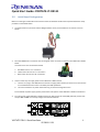
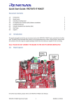
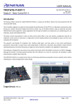
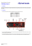
Quick Start Guide: YROTATE-IT-RX111
Document Contents
1.0
2.0
3.0
4.0
5.0
6.0
7.0
8.0
1.0
Introduction
Board Layout
Initial Board Configuration
PC Graphical User Interface (GUI) Software Installation
Installing USB Drivers
Using the Graphical User Interface (GUI)
Next Steps
Support
1
1
2
3
4
4
7
7
Introduction
This quick start guide assists the user to connect and use the YROTATE-IT-RX111 motor control kit for the first
time. The RX111 microcontroller flash memory is pre-programmed with a motor control project. Please check
the contents of the kit using the supplied package contents list and notify your supplier if any are missing.
Note: PLEASE DO NOT CONNECT THE BOARD TO THE HOST PC BEFORE INSTRUCTED
2.0
Board Layout
J7: Motor
Connector
J3-J4: External
Power Supply
Connectors
[24V MAX]
RX111
Motor Control MCU
J6: External
Power Stage
Connector
J1: USB
Connector
J5: E1
Connector
Power Supply
Selection
JP1, JP2
For further board details, please refer to the YROTATE-IT-RX111 User Manual.
YROTATE-IT-RX111 Quick Start Guide
1
D013602-11-S01
Quick Start Guide: YROTATE-IT-RX111
3.0
Initial Board Configuration
Before connecting the USB cable to the host PC and to the YROTATE-IT-RX111 board please follow the setup
procedure as described below.
1.
The demonstration 3-phase Permanent Magnet Motor comes pre-wired with its connector as shown
below.
2.
Place the PMSM motor connector into the assigned motor connector socket J7 on the YROTATE-IT-RX111
board.
The motor wires are connected as follows
a.
b.
c.
3.
Red Motor wire to “U” connection
Yellow motor wire to the “V” connection
Black motor wire to the “W” connection
There are two ways to supply power to the YROTATE-IT-RX111 board.
a. The first is to plug in the USB cable from the PC to supply power directly to the board. In this case the
current delivered to the motor is limited by the USB capabilities.
b. The second method is to power the board using an external voltage DC source.
For full details of power supply options please refer to Chapter 3 of the YROTATE-IT-RX111 User Manual.
4.
For initial setup of the YROTATE-IT-RX111 kit the first method must be used (USB powered). Ensure that
Jumpers JP1 and JP2 are correctly configured as described below.
YROTATE-IT-RX111 Quick Start Guide
2
D013602-11-S01
Quick Start Guide: YROTATE-IT-RX111
4.0
PC Graphical User Interface (GUI) Software Installation
Insert the Software CD into your computer’s CD-ROM drive. Windows™ Vista and 7, 8 users must install the
software on the CD with administration rights. User may see “User Account Control” dialog box. If applicable,
enter the administrator password and click <OK>. Else, browse to the CD root folder & Right Click on the
“MCDemoSetupx.x.exe” and select “Run as administrator”.
Click on <Install Motor Control Demo> on the installer opening screen and then follow the instructions until
reaching the final installer screen and then click <Finish>. At this stage do not click on <Start Demo>.
YROTATE-IT-RX111 Quick Start Guide
3
D013602-11-S01
Quick Start Guide: YROTATE-IT-RX111
5.0
Installing USB Drivers
The virtual UART drivers are included separately with the CD-ROM.
To install the virtual UART drivers
1. First connect the USB cable to the host PC and then connect to the YROTATE-IT-RX111 board.
2. The host PC will detect the new hardware and start the driver installation. Follow the Windows
instructions, selecting <NOT THIS TIME> to the request for an automatic driver search by Windows. Then
click on <SELECT A PATH> to select the appropriate YROTATE-IT-RX111 drivers on the CD-ROM in the
folder called “Drivers”.
3. If the automatic installation fails, the drivers can be manually installed. Browse the CD-ROM and double
click on the file “CDM20830_Setup.exe” in the folder “Drivers\YROTATE-IT-RX111 Drivers” and then
follow the installer instructions.
6.0
Using the Graphical User Interface (GUI)
The GUI is installed during the installation process, and must be run with administration rights. To start the GUI
Right-click on the Motor Control Demo ICON in the start menu or on the desktop and “Run as administrator”
Please note, that for Windows Vista and Windows 7, 8 users, the GUI must be run with administration rights.
To automatically set the admin privilege, press the right mouse button over the icon of the GUI, Select
“Properties”, press the Left mouse button on the “Compatibility” tab and Select the Checkbox “Run this
program as an administrator” under the Privilege Level, and click <OK>.
It is recommended that the USB cable should be connected to the PC and the board before opening the GUI as
this makes the connection process easier. The GUI can be opened without the board being connected.
YROTATE-IT-RX111 Quick Start Guide
4
D013602-11-S01
Quick Start Guide: YROTATE-IT-RX111
Once the GUI is open use the following procedure to connect the GUI to the YROTATE-IT-RX111 board.
•
•
•
•
•
Select the “Select board setup” drop down menu bar in the “Communication Settings” box in the top left
hand corner of the GUI panel.
Select the <RX111_Kit> option.
Select the “Serial port” drop down box.
Select the communications port connected to the YROTATE-IT-RX111 board (in this example COM5)
Click on the <Connect> button.
Once connected the GUI can be used to control the motor manually using the “RPM Control” facility. Here the
user can start, stop and set direction and speed of the motor, whilst observing its performance parameters
within the system display windows of the GUI.
The GUI can be closed by either clicking on the <Exit> button in the bottom left hand corner or the usual
windows close button.
All the facilities of the GUI, including the unique Auto-calibration feature are described in the YROTATE-ITRX111 User Manual.
YROTATE-IT-RX111 Quick Start Guide
5
D013602-11-S01
Quick Start Guide: YROTATE-IT-RX111
Speed range limitations
The YROTATE-IT-RX111 kit is driving any 3-phase Permanent Magnet Motors using a sensorless vector control
algorithm. So it means that there is a minimum speed to reach in order to run the motor properly using the
three shunts current measurement methods.
In the case of the Nanotec Motor DB42S03 delivered with the kit, the minimum speed is 500RPM. Below this
speed, the current flowing through the three shunts are too low to be detected.
Furthermore, when the board is supplied only via the USB cable, the maximum current provided to the board
is limited by the 500mA of the USB PC port and the voltage generating by the board which is 12V.
It means that, the first tests using the 3-phase Brushless AC motor DB42S03 from Nanotec will work properly in
a specific speed range: from 500RPM up to 2000RPM.
The DB42S03 brushless motor is able to reach its maximum speed of 6200RPM (without load) when the power
supply is 24V and up to 1A is provided.
After changing the jumpers as described above and providing 24V to the board, the Nanotec motor from the
YROTATE-IT-RX111 kit reach easily 6200RPM, its maximum rated speed without load. Of course, the embedded
software enabling flux weakening technics, by providing more current to the board, the motor can reach
8000RPM.
YROTATE-IT-RX111 Quick Start Guide
6
D013602-11-S01
Quick Start Guide: YROTATE-IT-RX111
7.0
Next Steps
After you have completed this quick start procedure, please review documentation that came with the kit,
especially the resources available on the CD-ROM.
The CD-ROM contains the resources described in the following table.
CD-ROM Folder
Auto-tuning Video-Tutorial
Drivers
YRMCKITRL78G14 Drivers
YROTATE-IT-RX62T Drivers
YROTATE-IT-RX220 Drivers
YROTATE-IT-RX111 Drivers
Embedded Software
E2Studio Source Code
IEC60730 Self Test MCU software
Manuals
Kit Motor Specifications
Renesas Datasheets
Tuned Motors Specifications
Schematics-Gerber-BoM
External Power Stage
Main Board
8.0
Description of Resources
Short video explaining how to easily tune any Brushless AC motor in 45 seconds
using just the intuitive PC Graphical User Interface
Drivers and setup files for the PC Graphical User Interface
Source files for code flashed by default into the Renesas microcontroller
Relevant documentation for the kit, the motor and the MCU
Schematics, Gerber files of Bill of Materials for both the main kit and the
external power stage (not included as part of the kit)
Support
Online technical support and further information is available at the following locations
Motor Control Websites
Europe:
www.renesas.eu/motor
America:
www.am.renesas.com/motorcontrol
Japan:
www.renesas.com/motorcontrol
General Web Resources
RenesasRulz Forum
Renesas Interactive Training
Renesas YouTube Channel
Renesas Europe on Facebook
Renesas Europe on Twitter
www.renesasrulz.com
www.renesasinteractive.com
www.youtube.com/user/RenesasPresents
www.facebook.com/RenesasEurope
www.twitter.com/Renesas_Europe
YROTATE-IT-RX111 Quick Start Guide
7
D013602-11-S01
Quick Start Guide: YROTATE-IT-RX111
©2014 Renesas Electronics Europe GmbH. All rights reserved
©2014 Renesas Electronics Corporation. All rights reserved
©2014 Renesas Electronics Solution Corp Ltd. All rights reserved
YROTATE-IT-RX111 Quick Start Guide
8
D013602-11-S01