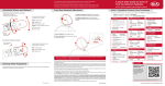
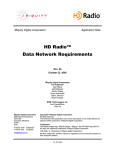
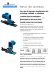
1
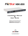
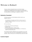
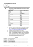
Importer Plus
Technical Instruction Manual
Document: IMPORTER_PLUS-MANUAL
Issue:
0.02 2010-03-29
Status:
Preliminary
Nautel Limited
10089 Peggy’s Cove Road
Hackett’s Cove, NS Canada B3Z 3J4
Phone: +1.902.823.3900 or
Toll Free: +1.877.6NAUTEL (6628835) (Canada & USA only)
Fax: +1.902.823.3183
Nautel Inc.
201 Target Industrial Circle
Bangor, Maine USA 04401
Phone: +1.207.947.8200
Fax: +1.207.947.3693
Customer Service (24 hour support)
+1.877.628.8353 (Canada & USA only)
+1.902.823.5100 (International)
Email: [email protected]
Web: www.nautel.com
The comparisons and other information provided in this document
have been prepared in good faith based on publicly available
information. The reader is encouraged to consult the respective
manufacturer's most recent published data for verification.
© Copyright 2010 NAUTEL. All rights reserved.
Importer Plus Technical Instruction Manual
Table of contents
Contents
Release control record
vii
About this manual
ix
Description
1-1
Overview
1-1
Physical requirements
1-4
Cooling requirements
1-5
Pre-installation tasks
2-1
Preparing for installation
2-1
Configuring the Importer Plus audio
2-2
Selecting a location for the Importer Plus
2-2
Planning the LAN connection
2-3
Synchronizing the SPS sample rate
2-6
Parts and tools
3-1
Parts supplied by nautel
3-1
Parts not supplied by nautel
3-2
Tools for installation
3-2
Page v
Importer Plus Technical Instruction Manual
Table of contents
Unpacking and installation
4-1
Connecting to the importer
5-1
Turning on the importer
6-1
Configuring the LAN
7-1
Operating the Importer Plus
8-1
Control panel
8-3
SPS processor
8-6
Changing service bandwidth allocation
Troubleshooting
8-14
9-1
Checking audio
9-1
Checking cable connections
9-2
Parts information
9-4
Routine maintenance
Checking the fans
List of terms
Page vi
10-1
10-1
11-1
Issue 0.02 2010-03-29
Importer Plus Technical Instruction Manual
Release control record
Issue
Date
Reason
0.01
2009-04-08
Initial release of manual
0.02
2010-03-29
Changes to support software release 2.3, including:
Section 8: “SPS Processor” procedure - added SPS3
information to Table 8.1; replaced Figure 8.6; edited
steps 3 through 7; deleted “Configuring the Importer
Plus to Auto-Start”
Issue 0.02 2010-03-29
Page vii
Importer Plus Technical Instruction Manual
Page viii
Issue 0.02 2010-03-29
Importer Plus Technical Instruction Manual
About this manual
This manual provides information about preparing for the delivery and installation of an Importer
Plus. This manual is intended for use by field technicians, site managers, and installation planners.
Using this manual
Read the task list provided in Section 2, “Pre-installation tasks” on page 2-1. The task list describes
the preparations you must make prior to receiving and installing the Importer Plus.
Later sections of this manual provide information regarding installation, operatiion and
troubleshooting.
Performing procedures
When using procedures in this manual, perform each step in sequence.
•
If you are asked to see another section of this manual, or another document, refer to that
section or document for additional information, and continue the procedure.
•
If you are asked to go to another step within the procedure, jump directly to that step without performing the intervening steps.
•
If you are asked to go to another section or document, stop the procedure and perform the
tasks described in the section or document.
CAUTION: FAILURE TO COMPLY WITH RECOMMENDATIONS MAY VOID YOUR
MANUFACTURER'S WARRANTY. FOR MORE INFORMATION, REVIEW YOUR
WARRANTY DOCUMENTS.
Note: When you have completed a task or a step, put a checkmark beside the step number.
Issue 0.02 2010-03-29
Page ix
Importer Plus Technical Instruction Manual
Features of this manual
This manual contains a number of useful features:
Online (PDF files)
•
Click on blue text (hyperlinks) to jump to a related section or get additional information (for
example, to view a definition of a term).
•
To find keywords, use Find in Acrobat Reader’s Edit menu.
•
To quickly find a specific section, click the section in the PDF file’s Bookmarks list.
Printed
•
To find keywords, go to the Index at the end of the manual.
•
To find a specific term, go to Section 8, “List of terms” on page 8-1.
Page x
Issue 0.02 2010-03-29
Importer Plus Technical Instruction Manual
Importer Plus manuals
The Importer Plus documentation suite contains the following documents:
Importer Plus Technical Instruction Manual, Importer Plus_Plus-MANUAL. The
Technical Instruction Manual provides instructions and reference information needed when planning
and preparing for the installation of an Importer Plus, installing an Importer Plus and operating,
maintaining and troubleshooting an Importer Plus. It also provides reference information needed
when performing diagnostic procedures.
HD Radio™ Importer Plus Users Guide. This guide provides detailed instructions for operating
the Importer Plus. It was produced by iBiquity and is provided as a supplement to the Operating and
Maintenance manual.
Both Importer Plus documents are also provided in Acrobat PDF format on the Nautel website, in
the Nautel User Group (NUG) section.
Online resources
The Nautel website provides useful resources to keep you up to date on your Importer Plus.
Nautel User Group (NUG)
The website includes a special section that customers can log into in order to access the Nautel
customer newsletter, product manuals, frequently asked questions (FAQ), information sheets, and
information about field upgrades.
Online documentation
The website’s NUG section provides online access to all the documentation for your Importer Plus.
Documentation is provided in Acrobat (PDF) format. You can use the documentation online or print
the sections that you need.
Issue 0.02 2010-03-29
Page xi
Importer Plus Technical Instruction Manual
Page xii
Issue 0.02 2010-03-29
Importer Plus Technical Instruction Manual
Description
Section 1: Description
This section provides a description of the Importer Plus and its associated digital radio system.
•
Overview
•
Physical requirements - see page 1-4
•
Cooling requirements - see page 1-5
Overview
The Importer Plus is used in digital radio transmission systems with Nautel's NE IBOC
(In-Band-On-Channel) signal generator (see Figure 1.2 on page 1-2) , Exporter (see Figure 1.3 on
page 1-2) or Exporter Plus (see Figure 1.4 on page 1-3) . The Importer Plus allows multiple
broadcasts within a single FM channel. It consists of a PC with compatible audio cards to support the
secondary program. The Importer Plus' application software enables partitioning of the available
transmitted HD (high definition) data bandwidth, between main program service (MPS) audio and
other audio and data services, collectively called advanced application services (AAS). Audio AAS are
called secondary program services (SPS), and include and program associated data (PAD).
The front panel has a hinged cover, behind which are LEDs to indicate hard drive activity (HDD)
and power, two USB ports and a power switch (see Figure 1.1). The rear panel has standard PC
connections for monitor, mouse, keyboard and a USB port. Installed audio card(s) include cables and
connectors for audio, and synchronizing inputs and outputs (specific to the type of audio card).
Figure 1.1: Importer Plus partial front view (behind hinged cover)
Issue 0.02 2010-03-29
Page 1-1
Importer Plus Technical Instruction Manual
Description
Figure 1.2: Typical system with an Importer Plus and NE IBOC
STUDIO
IMPORTER PLUS
TRANSMITTER SITE
LAN
NE IBOC
Audio
SPS Audio
MPS Audio
Data
FM EXCITER
To Transmitter
Note: The Importer Plus can also be located at the transmitter site. This requires sending SPS audio to the transmitter
site instead of through a LAN connection.
Figure 1.3: Typical system with an Importer Plus and Exporter
STUDIO
Delayed
MPS Audio
TRANSMITTER SITE
EXPORTER
ETHERNET
SWITCH
LAN
FM EXCITER
MPS Audio
To Transmitter
IMPORTER PLUS
SPS Audio
Note: The Importer Plus and Exporter can also be located at the transmitter site. This requires sending SPS audio to
the transmitter site instead of through a LAN connection.
Page 1-2
Issue 0.02 2010-03-29
Importer Plus Technical Instruction Manual
Description
Figure 1.4: Typical system with an Importer Plus and Exporter Plus
TRANSMITTER SITE
STUDIO
ETH0
LAN
EXPORTER PLUS
ETH1
MPS Audio
FM EXCITER
Delayed
MPS Audio
To Transmitter
IMPORTER PLUS
SPS Audio
Note: The Importer Plus and Exporter Plus can also be located at the transmitter site. This requires sending SPS
audio to the transmitter site instead of through a LAN connection.
Issue 0.02 2010-03-29
Page 1-3
Importer Plus Technical Instruction Manual
Description
Physical requirements
Figure 1.5: Importer Plus
Dimensions
The Importer Plus is a rack-mountable unit with the following dimensions:
•
Height:
1U, or 4.4 cm (1.75 inches)
•
Width:
48.3 cm (19 inches)
•
Depth:
44.0 cm (17.3 inches)
Clearances
Ensure there are minimum clearances of 1.3 m (4.0 feet) at the front and the rear of the Importer
Plus's host cabinet to allow room for installation, operation and ventilation. Allow several inches of
clearance at the sides of the Importer Plus.
Weight
The Importer Plus weighs 18 kg (40 lbs).
Page 1-4
Issue 0.02 2010-03-29
Importer Plus Technical Instruction Manual
Description
Cooling requirements
This section provides information about heating and cooling requirements for the Importer Plus.
•
Do not allow the Importer Plus room ambient air temperature to exceed 30°C (86°F)at sea
level. De-rate 3ºC (5.4°F) per 500 m – or 2ºC (3.6°F) per 1,000 feet – above sea level.
Example:
At 1,600 m (1 mile) above sea level, maximum ambient temperature should not exceed
20.4°C (67°F). Cooler temperatures are recommended, in order to improve the reliability of
the Importer.
•
Do not install the Importer Plus next to other warm equipment.
Issue 0.02 2010-03-29
Page 1-5
Importer Plus Technical Instruction Manual
Page 1-6
Description
Issue 0.02 2010-03-29
Importer Plus Technical Instruction Manual
Pre-installation tasks
Section 2: Pre-installation tasks
This section provides a list of tasks that you must perform prior to delivery and installation of the
Importer Plus.
CAUTION: FAILURE TO COMPLY WITH RECOMMENDATIONS MAY VOID
YOUR MANUFACTURER’S WARRANTY. FOR MORE INFORMATION, REVIEW
YOUR WARRANTY DOCUMENTS.
Preparing for installation
To prepare for installation of an Importer Plus, perform the following tasks:
1. Ensure the correct Importer configuration is ordered. Consider the audio card, SPS (analog
or AES), and equipment requirements. For detailed information, see “Configuring the
Importer Plus audio” on page 2-2.
2. Select a location for the Importer Plus in the studio or the transmitter site. For detailed
information, see “Selecting a location for the Importer Plus” on page 2-2.
3. Prepare the network (LAN) connection between the Importer Plus and the NE IBOC,
Exporter or Exporter Plus. Consider the Importer Plus's location and the amount of other
networked equipment at the transmitter site. For detailed information, see “Planning the
LAN connection” on page 2-3.
4. Consult your network manager to obtain IP address information for the Importer Plus, NE
IBOC, Exporter or Exporter Plus, and gateway. For detailed information, see “IP address
information” on page 2-5.
5. If you are going to use SPS sample rate synchronization, determine how it can best be
implemented.
For detailed information, see “Synchronizing the SPS sample rate” on page 2-6.
6. Order any accessories or optional equipment that you may need. See “Parts and tools” on
page 7-1.
7. Train your station technicians and operators on the use of the Importer Plus. For a list of
available technical and user documents, see the About this manual section at the beginning of
this document. For information about Nautel training courses, go to the Nautel website at
http://www.nautel.com/support/training/
Issue 0.02 2010-03-29
Page 2-1
Importer Plus Technical Instruction Manual
Pre-installation tasks
Configuring the Importer Plus audio
1. Importer Plus audio card configurations may differ depending on the options specified, but
in general, there will be two audio channels.
2. You must use AES format audio and the sample rate must be set to 44.1 kHz.
3. For best audio performance, synchronize the 44.1 kHz audio sample rate to the HD system
10 MHz reference. See also “Synchronizing the SPS sample rate” on page 2-6.
Selecting a location for the Importer Plus
To ensure that the desired location for the Importer Plus is suitable, perform the following tasks.
1. Determine whether the Importer Plus and its host cabinet will be located in the studio or the
transmitter site. Consider the following choices and associated requirements:
a) If you install the Importer Plus at the transmitter site with the associated NE IBOC,
Exporter or Exporter Plus, you will ease the connection required between the studio and the
transmitter site. In this case you will need to send only SPS audio to the Importer Plus rather
than a LAN connection. See also “Planning the LAN connection” on page 2-3.
b) If you install the Importer Plus at the studio, regardless of the location of the NE IBOC,
Exporter or Exporter Plus, you will need to provide a LAN connection over the studiotransmitter link (STL). Ensure the STL can support this capability. See also “Planning the
LAN connection” on page 2-3.
2. Ensure you have a cabinet and room space suitable for installing the Importer. See “Physical
requirements” on page 1-4 and “Cooling requirements” on page 1-5.
3. Ensure the Importer Plus is near a standard ac power outlet, 100 - 240 V ac.
Page 2-2
Issue 0.02 2010-03-29
Importer Plus Technical Instruction Manual
Pre-installation tasks
Planning the LAN connection
This section provides information about the LAN connection between the Importer Plus and the NE
IBOC, Exporter or Exporter Plus. Assess your existing network's capabilities, or establish a network
that meets the requirements of this section. This section includes the following topics:
• Managing network traffic
• STL capacity
• IP address information
Managing network traffic
Network traffic between the Importer Plus and NE IBOC, Exporter or Exporter Plus contains time
sensitive information, such as audio, and cannot tolerate variation in transport time. Use network
devices such as switches to intelligently route the network traffic. Avoid using network hubs, which
are slow in nature. The link between the Importer Plus and Exporter/NE IBOC is called I2E. The
link between the Exporter or Exporter Plus and FM exciter with Exgine option is called E2X.
Figure 2.1, Figure 2.2 and Figure 2.3 show examples of LAN configurations using the Importer Plus
and Exporter at various locations.
Figure 2.1: Example of Importer Plus and Exporter at the Transmitter Site
IMPORTER PLUS
I2E Link (< 150 kb/s)
4 Port
LAN
Switch
EXPORTER/
NE IBOC
FM EXCITER
Note: Dashed direction lines show logical data connections. Where data flows in both
directions, the larger arrowhead indicates the direction of the majority of the data.
Note: The FM exciter connects to the LAN when the exciter includes the Exgine option. Otherwise it can only connect
directly to an Exporter, Exporter Plus or NE IBOC.
Issue 0.02 2010-03-29
Page 2-3
Importer Plus Technical Instruction Manual
Pre-installation tasks
Figure 2.2: Example of an Importer at the Studio
IMPORTER PLUS
SPS PAD
AAS Data
I2E Link (< 150 kb/s)
Studio LAN
XMTR
SITE
4 Port
LAN
Switch
Digital STL
Note: Dashed direction lines show logical data
connections. Where data flows in both directions,
the larger arrowhead indicates the direction of the
majority of the data.
MPS PAD and other
transmitter site LAN
traffic.
Note: MPS PAD, SPS PAD, and AAS data are optional HD data services.
Figure 2.3: Example of an Importer and Exporter or Exporter Plus at the Studio
IMPORTER PLUS
SPS PAD
AAS Data
I2E
(< 150 kb/s)
Studio LAN
4 Port
LAN
Switch
EXPORTER
PLUS
XMTR
SITE
E2X
Digital STL
MPS PAD and other
transmitter site LAN
traffic.
Note: Dashed direction lines show logical data
connections. Where data flows in both directions,
the larger arrowhead indicates the direction of the
majority of the data.
Note: MPS PAD, SPS PAD, and AAS data are optional HD data services.
Page 2-4
Issue 0.02 2010-03-29
Importer Plus Technical Instruction Manual
Pre-installation tasks
Network switch. Incorporating a network switch (see Figure 2.1 on page 2-3) ensures that the
connection to the Importer Plus carries only SPS PAD and I2E data, and that the connection to the
digital STL carries only exciter link data, MPS PAD (for the NE IBOC, Exporter or Exporter Plus),
and any traffic for other devices at the transmitter site.
Network bandwidth. It is assumed that the Importer Plus and NE IBOC, Exporter or Exporter
Plus have fixed IP addresses. Because STLs have limited total throughput, the available networking
bandwidth depends on how much of the throughput is being used for audio or other services.
Determining available bandwidth depends on the type of STL and how it is being used.
STL capacity
The required STL capacity on the LAN channel varies based on protocol, service mode and the
number of secondary audio channels. You may require a bandwith of up to 150 kb/s.
IP address information
Since the Importer Plus will be connected to the NE IBOC, Exporter or Exporter Plus over a LAN,
you will need to determine the IP addresses for the Importer Plus, the NE IBOC, Exporter or
Exporter Plus, and the gateway. Consult with your network manager for this information. If they are
to be connected together directly, as shown in Figure 2.1 on page 2-3, the choice of IP address is
arbitrary. For example the following could be used:
•
NE IBOC, Exporter or Exporter Plus IP: 10.10.10.10
•
Importer Plus IP: 10.10.10.12
•
Gateway IP: 10.10.10.2
Issue 0.02 2010-03-29
Page 2-5
Importer Plus Technical Instruction Manual
Pre-installation tasks
Synchronizing the SPS sample rate
This section aids in assessing the feasibility of synchronizing the SPS sample rate to a 10 MHz
reference. This section includes the following topics:
•
General considerations
•
Methods to achieve synchronization
•
Additional equipment
General considerations
You can achieve the best SPS audio performance if you synchronize the Importer Plus’ 44.1 kHz
audio sample rate to the master clock of the HD system. The difference in audio quality may not be
perceptible, or even important, given that SPS channels are typically lower quality audio. To
synchronize, you may require considerable equipment infrastructure (see “Using an HD-4 audio
card” on page 2-8) depending on the system configuration.
The station manager should review Methods to achieve synchronization in this section and determine
whether it is a worthwhile investment.
Methods to achieve synchronization
There are different ways to synchronize the SPS audio sample rate, based on the number of channels
and the location of the Importer. Consider the following:
Using a GPS synchronization unit for single channel applications. Nautel supplies either
an NAX240 GPS Synchronization Unit, or a built-in GPS synchronization card, with NE IBOC or
Exporter. Both of thee devices include a 44.1 kHz word clock output that can be used as the
synchronization source for an Importer Plus.
Using an audio processor as a sample rate converter. Some audio processors can provide
the sample rate conversion function. An audio processor must be able to accept either a word clock
or another AES input as a synchronizing signal for its output AES sample rate.
Importer location. If the Importer Plus will be co-located with the NE IBOC, Exporter or
Exporter Plus, and a suitable audio processor will be used to condition the SPS audio, the audio
processor may be able to perform the synchronization. See Figure 2.4 for a block diagram of this
setup.
Page 2-6
Issue 0.02 2010-03-29
Importer Plus Technical Instruction Manual
Pre-installation tasks
Figure 2.4: Using an audio processor for SPS synchronization
SPS Audio
SPS Audio
(locked)
Audio
Processor
IMPORTER PLUS
Word Clock
44.1 kHz
EXPORTER/
NE IBOC
MPS Audio
(locked)
GPS SYNCH
MPS Audio
Note: Commercial sample rate converters are also
available which can be used instead of an audio
processor.
Importer Plus and Exporter or NE IBOC co-located
If the Importer Plus will not be co-located with the NE IBOC, Exporter or Exporter Plus, you can
purchase a second GPS synchronization unit to install near the Importer Plus. Both units must be
GPS locked to satellite. Since the GPS synchronization unit can only synchronize a single audio
source, you will need to use the GPS synch word clock, or a spare AES output, as an input to a
sample rate converter (audio processor) if you are using more than one SPS. See Figure 2.5 on page
2-8 for a block diagram of this setup.
Issue 0.02 2010-03-29
Page 2-7
Importer Plus Technical Instruction Manual
Pre-installation tasks
Figure 2.5: Multiple SPS
SPS1 Audio
SPS1 Audio
(locked)
Audio
Processor
IMPORTER PLUS
Word Clock
44.1 kHz
SPS2 Audio
SPS2 Audio
(locked)
GPS SYNCH
Note: Commercial sample rate converters are also
available which can be used instead of an audio
processor.
Importer Plus and NE IBOC or Exporter not co-located
Using an HD-4 audio card. Some Importers include a Prodif HD-4 audio card (Nautel Part #
UA100). This card has a single BNC type connector which is a word clock input. Applying the
44.1 kHz word clock to this input will synchronize the Importer Plus audio.
Additional equipment
You need the following additional equipment to synchronize the SPS audio sample rate:
•
GPS receiver with a 10 MHz output (also part of GPS synchronization unit/card)
•
Word clock generator that accepts a 10 MHz reference (also part of GPS synchronization
unit/card)
•
Sample rate converter or suitable audio processor (one per channel) that accepts an external
sample rate word clock
Page 2-8
Issue 0.02 2010-03-29
Importer Plus Technical Instruction Manual
Parts and tools
Section 3: Parts and tools
This section describes parts associated with the Importer Plus, and tools needed during installation
and routine operation.
•
Parts supplied by Nautel
•
Parts not supplied by Nautel – see page 3-2
•
Tools for installation – see page 3-2
Parts supplied by nautel
Audio card ancillaries
With each audio card that is purchased, a plastic bag is provided containing audio cables. You may not
require all cables for your Importer Plus installation.
Ac power cable
An ac power cable is included with the Importer Plus.
Software
The CD containing the Microsoft Windows XP Professional software is included with the Importer
Plus. Nautel pre-loads the Importer Plus so you do not need to install it initially. It is provided if you
need to re-install it at a later date.
Documentation
Nautel includes the following documents with the Importer Plus:
•
Importer Technical Instruction Manual, IMPORTER_PLUS-MANUAL.
The Technical Instruction Manual provides instructions and reference information needed when
planning and preparing for the installation of an Importer Plus, installing an Importer Plus,
and operating and maintaining an Importer Plus. It also provides reference information
needed when performing diagnostic procedures.
•
HD Radio Importer User's Guide.
The HD Radio Importer User's Guide provides detailed instructions for operating an Importer
Plus. It is provided as a supplement to the Technical Instruction Manual.
Issue 0.02 2010-03-29
Page 3-1
Importer Plus Technical Instruction Manual
Parts and tools
Parts not supplied by nautel
Nautel does not supply some parts and materials required to complete installation. The parts you
need vary with the installation requirements. The list of parts you normally provide yourself during
installation include:
•
19-inch cabinet space
•
USB PC keyboard and mouse
•
Monitor
•
Cat-5 cable
•
SPS audio sources
Tools for installation
The tools you need during Importer Plus installation include the following:
•
Philips screwdrivers, sizes # 1 and # 2
Page 3-2
Issue 0.02 2010-03-29
Importer Plus Technical Instruction Manual
Unpacking and installation
Section 4: Unpacking and installation
To install an Importer Plus, perform the following tasks:
1. Unpack the Importer Plus from shipping box. Make sure that all shipped items are available
- check your packing list.
2. Inspect all crates and packages for damage. Report any damage immediately to your Nautel
sales representative.
3. Assemble your parts and tools. For a list of required tools, see “Parts and tools” on page 3-1.
4.
the Importer Plus at the studio or transmitter site in the cabinet space you have prepared.
5. Do not connect ac power to the Importer Plus at this time.
Issue 0.02 2010-03-29
Page 4-1
Importer Plus Technical Instruction Manual
Page 4-2
Unpacking and installation
Issue 0.02 2010-03-29
Importer Plus Technical Instruction Manual
Connecting to the importer
Section 5: Connecting to the importer
To connect the Importer Plus audio cable, perform the following steps:
1. Locate the cable harnesses supplied in plastic bag.
Note: The audio card(s) shipped in the Importer Plus are optional item(s) and, as such, may differ between
Importer Plus units. Audio cable(s) that are designed to work with the installed audio card will be shipped
with the unit; the audio channels are indicated on these cables.
2. Connect the USB keyboard and mouse, and the monitor to the Importer Plus (see
Figure 5.1).
Figure 5.1: Importer Plus rear panel connections
to
Exporter/
NE IBOC
Cooling
Fan
Ac Power
Connector
PS2 Keyboard
Audio Cards
or
(bottom card not installed)
Mouse
Issue 0.02 2010-03-29
USB
Monitor
Page 5-1
Importer Plus Technical Instruction Manual
Page 5-2
Connecting to the importer
Issue 0.02 2010-03-29
Importer Plus Technical Instruction Manual
Turning on the importer
Section 6: Turning on the importer
To turn on and boot up the Importer Plus, perform the following steps:
1. Connect ac power to the back of the Importer Plus. The Importer Plus will begin booting
up.
Note: There is a momentary I/O switch on the front panel that turns the Importer Plus on and off. When the
Importer Plus is on and the switch is pressed, Windows XP will routinely shut down and turn off the power
supply. When the Importer Plus has been shut down in this manner and the switch is pressed again, the
Importer Plus will turn on.
2. Ensure the monitor is turned on and that Windows XP starts up properly.
Figure 6.1: Importer Plus partial front view (shown without cover)
On/Off
(momentary)
Switch
Issue 0.02 2010-03-29
Reset
Switch
Page 6-1
Importer Plus Technical Instruction Manual
Turning on the importer
Page 6-2
Issue 0.02 2010-03-29
Importer Plus Technical Instruction Manual
Configuring the LAN
Section 7: Configuring the LAN
Perform the steps in this section to configure the Importer Plus’ IP addresses.
Note: IP address information for the Importer Plus and NE IBOC, Exporter or Exporter Plus, based on LAN
configuration, was determined in “Planning the LAN connection” on page 2-3. The equipment has been factory preconfigured with a default NE IBOC, Exporter or Exporter Plus IP address of 10.10.10.10. Even if modifications
are not required, you should verify that the IP addresses are correct.
Modify the Importer Plus’ IP address for the NE IBOC, Exporter or Exporter Plus as follows:
1. From the Importer Plus’ control panel:
•
•
Select Setup > Importer
Enter the Exporter IP address in the Exporter IP field (see Figure 7.1 ).
Figure 7.1: Importer Setup screen
Issue 0.02 2010-03-29
Page 7-1
Importer Plus Technical Instruction Manual
Configuring the LAN
2. Modify the IP address of the Importer Plus as follows:
•
•
•
•
•
•
•
•
•
•
•
Select the Network Connections icon.
Right click on Local Area Connection.
Select Properties.
Scroll to and highlight Internet Protocol.
Click on Properties.
In the Properties window, click the Use the following IP address option.
Enter the importer's IP address in the IP address field (see your network manager).
Check the Subnet mask. It should be: 255:255:255:0
If necessary, enter the gateway IP address in the Default gateway field (see your
network manager).
Click OK.
Click OK again.
3. Verify the IP address of the Importer Plus as follows:
•
•
•
•
Using another PC that is directly or indirectly (via a switch) network connected to the
importer, select: Start > All Programs > Accessories > Communications > Command Prompt
At the command prompt, type: ping importer IP address
The ping command should show the status of four packets sent to the Importer Plus. If
the connection is OK, a response similar to Figure 7.2 should appear.
Type exit to close the Command Prompt window.
Figure 7.2: Successful importer ping response
Page 7-2
Issue 0.02 2010-03-29
Importer Plus Technical Instruction Manual
Operating the Importer Plus
Section 8: Operating the Importer Plus
This section provides information about operating the Importer Plus:
•
License key - see page 8-1
•
Control panel- see page 8-3
•
SPS processor - see page 8-6
•
WebAdmin client- see page 8-9
•
Backing up the configuration database - see page 8-17
Note:The procedures in this section allow you to quickly configure the importer for standard operation. For detailed
procedural and reference information, refer to Section 8, Operating Procedures of the HD RadioTM Importer
User's Guide provided with this documentation.
License key
The Importer Plus will not function without a valid license key issued by iBiquity Digital. The
following steps describe how to check and renew your license key.
1. You can check the expiry date of the Importer Plus license by opening the LicenseMgr
application from the Start menu.
•
From the Start menu:
Click on Start > Programs > iBiquity Digital > Importer > LicenseMgr.
Issue 0.02 2010-03-29
Page 8-1
Importer Plus Technical Instruction Manual
Operating the Importer Plus
Figure 8.1: License Manager
2. If your license is about to expire, click on the Get Request Key button. A 48-character
code – the Request Key – will appear in the box below the button.
3. Email the Request Key to [email protected]. A 48-character activation code – the
License Key – will be provided via return email.
4. Enter the License Key in the License Key box, then click on the Activate button.
Note:The request code is based on the Importer Plus’ present date as well as the MAC address of the Importer Plus’
Ethernet port. Only the request code that was emailed to Ibiquity will work with the assigned License Key. You may
need to manually re-enter the request code if License Manager is closed and the date advances prior to entering the
new key.
5. Verify that the date in the Current License Status box has advanced by approximately one
year.
Page 8-2
Issue 0.02 2010-03-29
Importer Plus Technical Instruction Manual
Operating the Importer Plus
Control panel
The Importer Plus software consists of a number of modules. These modules may be started and run
individually, bu tthe preferred method is to run the Importer Control Panel application. This manual
contains information on running the Importer Plus software through the Importer Control Panel.
For detailed information on the individual modules, see the HD Radio Importer User’s Manual.
Start up the Importer Control Panel as follows:
1. Ensure the Importer Plus is connected to the NE IBOC, Exporter or Exporter Plus via
Ethernet.
2. From the Windows desktop, double click the Importer Control Panel icon. The control
panel application will start. See Figure 8.2
Figure 8.2: Importer Control Panel
Control panel functions
The Importer Control Panel allows the user to start and stop the Importer Plus, set various Importer
Plus configuration options and control the Importer Plus’ logging functions.
Issue 0.02 2010-03-29
Page 8-3
Importer Plus Technical Instruction Manual
Operating the Importer Plus
Starting the Importer Plus: Click the start icon to start the Importer Plus. A properly
configured and connected Importer Plus will display a number of log messages
indicating that the various modules have started successfully.
Stopping the Importer Plus: Click the stop icon to stop the Importer Plus. The icon
appears in place of the start icon once the Importer Plus is started.
Importer Plus Setup: Click the setup icon to enter the Importer Setup screen. See
Figure 8.3. Typically the only setting which may be altered on this screen is the Exporter
IP address.
Figure 8.3: Importer Setup Screen
Page 8-4
Issue 0.02 2010-03-29
Importer Plus Technical Instruction Manual
Operating the Importer Plus
Log Service Setup: Click the log service icon to set up the event logging parameters of
the Importer Plus. The screen shown in Figure 8.4 should appear. Log levels, log file
sizes and log file locations can be specified from this screen.
Figure 8.4: Log Service Setup Screenl
Issue 0.02 2010-03-29
Page 8-5
Importer Plus Technical Instruction Manual
Operating the Importer Plus
Disable Log Message Display: Click the print log icon to enable or disable the printing
of log messages on the Importer Control Panel. When enabled, normal log messages
are displayed in blue text. Error messages are displayed in red text. Warning messages are
displayed in yellow text. Debug messages are displayed in black text.
Other functions: Additional icons exist that allow for saving, printing, erasing and searching log files.
SPS processor
Use the SPS Processor application as follows:
1. From the Importer Plus’ desktop, double click on the SPS Capture 1 icon. The SPS Capture
application will start and the screen shown in Figure 8.5 will appear.
Figure 8.5: SPS Capture screen
2. Enter the User name and Password and click OK. The screen shown in Figure 8.6 will
appear. The User name and Password are non-volatile and will not need to be entered every
time the SPS processor is started up. The default User names and Passwords for the two
secondary channels are shown in Table 8.1.
Table 8.1: Default User Names and Passwords
Channel
User Name
Password
SPS1
sps_one
sps_one_pwd
SPS2
sps_two
sps_two_pwd
SPS3
sps_three
sps_three_pwd
Page 8-6
Issue 0.02 2010-03-29
Importer Plus Technical Instruction Manual
Operating the Importer Plus
Figure 8.6: SPS Configuration screen
3. Select Lynx AES16-SRC Device 1 for SPS1.
4. Select Lynx AES16-SRC Device 2 for SPS2.
5. Select Lynx AES16-SRC Device 3 for SPS3.
6. Use the Settings pull-down menu to configure several parameters of the SPS Capture Client
(see Figure 8.7).
Issue 0.02 2010-03-29
Page 8-7
Importer Plus Technical Instruction Manual
Operating the Importer Plus
Figure 8.7: Settings Pull-down Menu
•
Checking the Auto Start checkbox will cause the capture client to bypass the Username/
Password dialog and directly enter the Capture Client.
•
You can change the PAD Port value for the Client. Typically, SPS1 uses port 10010, SPS2
uses port 10020 and SPS3 uses port 10030.
•
You can add additional packet buffering if there are dropouts on the link between the
Importer Plus and Exporter. This may occur on a link between an Importer Plus located
at the studio and an Exporter located at the transmitter site.
7. Click on the Send button to start the process.
Page 8-8
Issue 0.02 2010-03-29
Importer Plus Technical Instruction Manual
Operating the Importer Plus
WebAdmin Client
The importer WebAdmin client is an application used to perform administration functions - such as
service provider registration, service definition and configuration management - on the Importer
Plus.
Figure 8.8 shows the SignIn screen for the WebAdmin client. The Importer Plus is shipped with a
default User ID (“admin”) and a Password (“admin”). You can change the password from within the
WebAdmin client.
Figure 8.8: WebAdmin SignIn screen
Once you enter the WebAdmin User ID and Password, the page shown in Figure 8.9 will appear.
There are five tabs at the top, each of which opens a different WebAdmin page.
Issue 0.02 2010-03-29
Page 8-9
Importer Plus Technical Instruction Manual
Operating the Importer Plus
Exporter page
The Exporter page (see Figure 8.9) displays the current exporter configuration including present
service mode as well as the channel configuration. It will also indicate if the Importer Plus and
Exporter are not synchronized.
Take care to ensure that the exporter is synchronized whenever a change is made to an Importer Plus
configuration. Do this before attempting to broadcast any AAS sevices. If the Importer Plus and
Exporter need synchronization, a message indicating the reason, as well as a Synchronize button, will
also appear (see Figure 8.10).
Figure 8.9: Exporter page
Page 8-10
Issue 0.02 2010-03-29
Importer Plus Technical Instruction Manual
Operating the Importer Plus
Figure 8.10: Synchronize page
Issue 0.02 2010-03-29
Page 8-11
Importer Plus Technical Instruction Manual
Operating the Importer Plus
Importer page
The Importer page (see Figure 8.11) displays current configuration and allows the user to change the
active configuration.
Figure 8.11: Importer page (view configurations)
The Next, Previous and Jump To ID buttons are used to cycle through all of the available
configurations. The Set button is used to change the configuration.
Monitor page
The Monitor page is simply a placeholder for future features.
Page 8-12
Issue 0.02 2010-03-29
Importer Plus Technical Instruction Manual
Operating the Importer Plus
Administration page
The Administration page (see Figure 8.12) provides access to multiple pages - Service Providers,
Services and Configuration.
The following section describes how to change audio bandwidth allocation in a configuration. Refer
to the Importer HD User’s Guide to change other parameters such as modifying service provider or
services.
Figure 8.12: Administration page
Issue 0.02 2010-03-29
Page 8-13
Importer Plus Technical Instruction Manual
Operating the Importer Plus
Changing service bandwidth allocation
One of the primary functions which can be performed from the Administration page (see
Figure 8.12) is the allocation of bandwidths for the various services.
Change your bandwidth allocation as follows:
1. From the Administration page select a Configuration. It will be highlighted orange. The
currently active configuration will also be highlighted in orange (see Figure 8.13).
Figure 8.13: Edit Configuration
2. Select the blue Edit button to move to the next dialog. Each of the audio services is displayed
as shown in Figure 8.14. The additional available bandwidth is also indicated.
Page 8-14
Issue 0.02 2010-03-29
Importer Plus Technical Instruction Manual
Operating the Importer Plus
Figure 8.14: Bandwidth Allocation for Audio Services
3. Select the Change button associated with the service to be changed. Change the bandwidth
by editing the value in the CoreBW (Bits/Sec) column. Once a new value has been entered,
select the OK button. The available bandwidth (AvailBw) numbers for the various channels
will update (see Figure 8.15)
Figure 8.15: Available Bandwidth after Change
4. Select the Update Configuration button in the upper right portion of the page (see
Figure 8.16).
Issue 0.02 2010-03-29
Page 8-15
Importer Plus Technical Instruction Manual
Operating the Importer Plus
Figure 8.16: Update Configuration
5. To implement this changed configuration, return to the Importer page (see Figure 8.11).
Page 8-16
Issue 0.02 2010-03-29
Importer Plus Technical Instruction Manual
Operating the Importer Plus
Backing up the Configuration Database
It is important that any changes made in the Importer Plus configuration (service providers, service
bandwidths, contracts, etc.) are saved in a safe location. This will allow system restoration if a
hardware failure occurs, or a mistake is made while modifying the configuration.
The Importer Plus includes an application, the DB (database) Administration Wizard, for backing up
or restoring the database.
1. Run the application by double clicking the DBAdmin icon on the Importer Plus desktop.
The screen shown in Figure 8.17 will appear.
Figure 8.17: DB Administration Wizard Welcome screen
2. Select Backup Importer Database and click on Start.
3. Enter a path and name for the backup database. Click Next. The screen in Figure 8.19 will
appear.
4. Click the Backup Now button. When the backup process is complete, click Finish to exit.
Issue 0.02 2010-03-29
Page 8-17
Importer Plus Technical Instruction Manual
Operating the Importer Plus
Figure 8.18: DB Administration Set Backup Database screen
Figure 8.19: DB Administration Backup and Finish screen
Page 8-18
Issue 0.02 2010-03-29
Importer Plus Technical Instruction Manual
Troubleshooting
Section 9: Troubleshooting
This section provides instructions you need when responding to an Importer Plus or system fault.
This section includes the following topics:
•
Checking audio - see page 9-1
•
Checking cable connections - see page 9-2
•
Parts information - see page 9-4
Checking audio
Use the Windows XP software associated with the audio card to troubleshoot potential audio
problems as follows:
1. Click on the icon at the bottom of the Windows XP taskbar that displays the HD4 settings
dialog (see Figure 9.1). Select Inputs from the list.
Figure 9.1: HD4 Dialog and HD4 Inputs Screen
2. When the SPS application is running, the audio level bars on the inputs screen (see
Figure 9.1) will indicate the audio levels.
Issue 0.02 2010-03-29
Page 9-1
Importer Plus Technical Instruction Manual
Troubleshooting
Checking cable connections
Verify that the Importer Plus’ internal cables are connected properly as follows:
1. Remove the Importer Plus’ top cover.
2. Inspect the cables and connections. If a connector is unseated or disconnected, ensure it is
reconnected to its mate as identified in Table 9.1. If necessary, see Figure 9.2 on page 9-3 to
identify the importer's sub-assemblies.
Table 9.1: Internal Connector Mating Information
Connector
Mate
P1
U1 CPU12V1
P2
U8 Power
P3
U1 F_PANEL1-RESET
P4
U1 F_PANEL1-PWR BUTTON
Red 7 Black 9
P5
U1 F_PANEL1-PWR LED
Red 1 Black 5
P6
U1 F_PANEL1-HDD LED
Red 11 Black 13
P7
CPU_FAN1
P8
U1_USB00
Red Pin 1
P9
U1_USB01
Black Pin 2
P10
U5_BP_ATXCTL1
P11
U1_ATXCTL1-PS-ON
P12
U1_ATXCTL1-5VSB
W1P1
U1 SATA1
W1P2
U8 SATA
Page 9-2
Notes
Red 12 Black 14
Yellow 2
Red 3
Issue 0.02 2010-03-29
Importer Plus Technical Instruction Manual
Troubleshooting
Figure 9.2: Importer Plus Sub-assemblies
U1
U6 *
U7 *
U4
U5
U3
U2
B1
U8
* - Audio cards U6 and U7 are optional items
Issue 0.02 2010-03-29
Page 9-3
Importer Plus Technical Instruction Manual
Troubleshooting
Parts information
For the purposes of identifying and possibly ordering replacement parts, the Importer Plus’ internal
assemblies are identified in Table 9.2. The table provides the reference designation, a description, and
the Nautel part number for each item.
Table 9.2: Importer Plus Parts List
Reference
Designation
Description
Nautel Part #
B1
Fan, 1U LGA775 Side Blow CPU Cooler
ZAP49
U1
SBC, PICMG 1.0, LGA775, Core2/P4
UA140
U2
IC, CPU, Core 2 Duo, LGA775,SLA99, E4300
UR104
U3
Memory, 1G, DDR2, 667MHz
UX117
U4
Memory, 1G, DDR2, 667MHz
UX117
U5
1U Rackmount Chassis, PCI BP, 250W
UW107
U6
Sound/Audio Card, Optional
UA100, UA141, UA142, etc.
U7
Sound/Audio Card, Optional
UA100, UA141, UA142, etc.
U8
HardDrive, Solid State, 32G,SATA
UX111
W1
Cable, SATA, .5m, Straight to Straight
UA90
Page 9-4
Issue 0.02 2010-03-29
Importer Plus Technical Instruction Manual
Routine maintenance
Section 10: Routine maintenance
This section provides instructions for performing routine maintenance on the Importer Plus. This
section includes the following topics:
•
Checking the fans - see page 10-1
•
Cleaning the fan filter - see page 10-2
Checking the fans
The Importer Plus contains three operational cooling fans (see Figure 2.4 on page 2-6). In order to
maintain your Importer Plus warranty and prevent premature component failures, check the fans
periodically.
Interval
•
Every six months in typical environments.
•
Every three months in dusty, humid or harsh environments.
Procedure
Take the following steps to check the fans:
1. Remove the Importer Plus’ top cover. If possible, allow the Importer Plus to continue
normal operation.
2. Verify that the three cooling fans are turning at an acceptable speed and that there are no
visible obstructions.
3. If you need to closely inspect a fan, clear an obstruction, or replace a fan, you must turn off
the Importer Plus. You should also remove the ac power connection at the back of the
Importer Plus.
Issue 0.02 2010-03-29
Page 10-1
Importer Plus Technical Instruction Manual
Routine maintenance
Cleaning the fan filter
In order to maintain your Importer Plus warranty and prevent premature component failures, clean
your importer's fan filter periodically.
Interval
Every six months in typical environments. Every three months in dusty, humid or harsh
environments.
Procedure
Take the following steps to clean the Importer Plus’ fan filter:
1. Open the Importer Plus’ front cover.
2. Remove the four Philips screws, which hold the fan cover, on the left side of the Importer
Plus’ front panel, in place.
3. Clean the fan filter using soap and warm water. If the fan filter is damaged, replace it
immediately.
4. Reinstall the fan filter.
5. Close the front cover if desired.
Page 10-2
Issue 0.02 2010-03-29
Importer Plus Technical Instruction Manual
List of terms
Section 11: List of terms
This section defines some of the terms that are used in Nautel documentation.
AAS. Advanced Application Services
AES-EBU. Audio Engineering Society/European Broadcasting Union (AES/EBU) is the name of a
digital audio transfer standard. The AES/EBU digital interface is usually implemented using 3-pin
XLR connectors (the same type of connector used in professional microphones). One cable carries
both left- and right-channel audio data to the receiving device.
Cat-5. Short for Category 5. Network cabling that consists of four twisted pairs of copper wire
terminated by RJ45 connectors.
GPS Synchronization Unit. The GPS synchronization (or synch) unit accepts the studio feed
audio in AES/EBU format and converts it to the 44.1 kHz sampling rate used throughout the
system. The GPS synch unit also contains the GPS receiver that locks onto the Global Positioning
System, and determines the site location and time. This information is then passed onto the NE
IBOC to be transmitted as part of the station information. The GPS receiver also provides 10 MHz
and 1 PPS signals that are used within the NE IBOC for synchronization purposes.
EOC. Ensemble Operations Center.
EXGINE. An HD™ Radio component which resides in the exciter. The Exgine decodes the Exciter
link data and produces the appropriate I/Q modulation.
GPS. The Global Positioning System is a system of satellites and receiving devices used to compute
positions on the Earth.
GUI. Graphical User Interface
HD™ Radio. High definition (HD) Radio is another term for In Band On Channel (IBOC)
technology. HD Radio is a trademark of the Ibiquity Digital Corporation.
IBOC. Nautel In-Band-On-Channel technology provides high quality digital audio over existing AM
and FM radio channels.
LAN. Local Area Network.
MPS. Main Program Service
Issue 0.02 2010-03-29
Page 11-1
Importer Plus Technical Instruction Manual
List of terms
NE IBOC. Nautel’s In-Band-On-Channel signal generator. See IBOC. Required for XR series IBOC
installations.
PAD. Program-Associated Data.
SPS. Supplemental Program Service. Sometimes called SAC. In initial tests, NPR called this
Tomorrow Radio.
STL. Studio-transmitter Link. A studio-transmitter link sends a radio station's audio signals from a
broadcast studio to a transmitter located some distance away from the studio.
TSL. Transmitter-studio Link. A transmitter-studio link returns data (e.g., monitoring information)
from a transmitter site to a broadcast studio located some distance away from the transmitter.
UDP. User Datagram Protocol. A core internet protocol whereby programs on networked computers
can send short messages between one another.
VNC. Virtual Network Connection.
XLR. A 3-pin connector used for a balanced audio cable. Used in pro-audio equipment and
AES/EBU digital audio.
Page 11-2
Issue 0.02 2010-03-29
Importer Plus
Technical Instruction Manual
Document: IMPORTER_PLUS-MANUAL
Issue:
0.02 2010-03-29
Nautel Limited
10089 Peggy’s Cove Road
Hackett’s Cove, NS Canada B3Z 3J4
Phone: +1.902.823.3900 or
Toll Free: +1.877.6NAUTEL (6628835) (Canada & USA only)
Fax: +1.902.823.3183
Nautel Inc.
201 Target Industrial Circle
Bangor, Maine USA 04401
Phone: +1.207.947.8200
Fax: +1.207.947.3693
Customer Service (24 hour support)
+1.877.628.8353 (Canada & USA only)
+1.902.823.5100 (International)
Email: [email protected]
Web: www.nautel.com
© Copyright 2010 NAUTEL. All rights reserved.