1
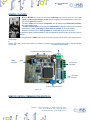
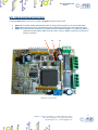
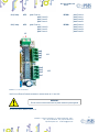
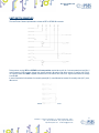
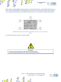
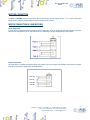
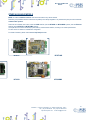
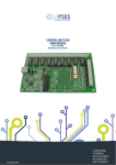
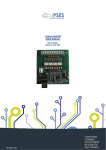
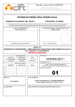
MT2 AND MT2MS USER MANUAL Rel. 01.04.0002 (Hardware code: MT2-S-2004 AND MT2-S-MS-2004) 1 www.ipses.com MT2 AND MT2MS USER MANUAL _____________________________ Information provided in this manual is property of IPSES S.r.l. and must be considered and treated as confidential. This publication can only be reproduced, transmitted, transcribed or translated into any human or computer language with the written consent of IPSES S.r.l. Information in this documentation has been carefully checked and is believed to be accurate as of the date of publication; however, no responsibility is assumed of inaccuracies. IPSES will not be liable for any consequential or incidental damages arising from reliance on the accuracy of this documentation. Information contained in this manual is subject to change without notice and does not represent a commitment on the part of IPSES. The design of this instrument is subject to continue development and improvement. Consequently, the equipment associated to this document may incorporate minor changes in detail from the information hereafter provided. All brand or product names are trademarks or registered trademarks of their respective holders. This manual in English is the original version. Printed in Italy Copyright 2009-2015IPSES S.r.l. All rights reserved. 2 IPSES S.r.l. Via Suor Lazzarotto, 10 - 20020 Cesate (MI) - ITALY Tel. (+39) 02 39449519 Fax (+39) 02 700403170 http://www.ipses.com e-mail [email protected] MT2 AND MT2MS USER MANUAL GUARANTEE IPSES warrants to the end-user in accordance with the following provisions that its branded hardware products, purchased by the end-user from IPSES company or an authorized IPSES distributor will be free from defects in materials, workmanship and design affecting normal use, for a period of one year as of the original purchase date. Products for which proper claims are made will, at IPSES’s option, be repaired or replaced at IPSES’s expense1. Exclusions This Guarantee does not apply to defects resulting from: improper or inadequate installation, use or maintenance; actions or modifications by unauthorized third parties or the end-user; accidental or wilful damage or normal wear and tear. Making a claim Claims must be made by contacting IPSES office within the guarantee period. Please, contact: IPSES S.r.l. - Via Suor Lazzarotto, 10 - 20020 Cesate (MI) Italy Tel. (+39) 02 39449519 – (+39) 02 320629547 Fax (+39) 02 700403170 http://www.ipses.com - e-mail: [email protected] Limitation and Statutory Rights IPSES makes no other warranty, guarantee or like statement other than as explicitly stated above and this Guarantee is given in place of all other guarantees whatsoever, to the fullest extent permitted by law. In the absence of applicable legislation, this Guarantee will be the end-user’s sole and exclusive remedy against IPSES. General Provisions IPSES makes no express warranties or conditions beyond those stated in this warranty statement. IPSES disclaims all other warranties and conditions, express or implied, including without limitation implied warranties and conditions of merchantability and fitness for a particular purpose. IPSES’s responsibility for malfunctions and defects in hardware is limited to repair and replacement as set forth in this warranty statement. IPSES does not accept liability beyond the remedies set forth in this warranty statement or liability for incidental or consequential damages, including without limitation any liability for products not being available for use or for lost data or software. 1 With the exclusion of shipping costs for and from IPSES’s development office. 3 IPSES S.r.l. Via Suor Lazzarotto, 10 - 20020 Cesate (MI) - ITALY Tel. (+39) 02 39449519 Fax (+39) 02 700403170 http://www.ipses.com e-mail [email protected] MT2 AND MT2MS USER MANUAL WARNING! ELECTRICAL DEVICES COULD DAMAGE EQUIPMENT OR PROPERTY OR CAUSE PERSONAL INJURY This guide contains instructions and technical features of the MT2 AND MT2MS. Read with attention before attempting to install. It is the responsibility of the technician to undertake all the safety rules provided by the law during the installation and the use of this device. For any information which is not contained in this guide, please contact: IPSES S.r.l. - Via Suor Lazzarotto, 10 - 20020 Cesate (MI) Italy Tel. (+39) 02 39449519 – (+39) 02 320629547 Fax (+39) 02 700403170 http://www.ipses.com - e-mail: [email protected] 4 IPSES S.r.l. Via Suor Lazzarotto, 10 - 20020 Cesate (MI) - ITALY Tel. (+39) 02 39449519 Fax (+39) 02 700403170 http://www.ipses.com e-mail [email protected] MT2 AND MT2MS USER MANUAL TABLE OF CONTENTS REVISION HISTORY .......................................................................................................................................................... 6 GENERAL FEATURES ....................................................................................................................................................... 7 REMOTE CONTROL COMMUNICATION PROTOCOL ..................................................................................................... 7 MT2 CONFIGURATION INSTRUCTIONS ........................................................................................................................ 12 MT2MS CONFIGURATION INSTRUCTIONS................................................................................................................... 13 MT2 CONNECTION INSTRUCTIONS .............................................................................................................................. 15 MT2MS CONNECTION INSTRUCTIONS......................................................................................................................... 16 CONNECTION .................................................................................................................................................................. 17 LIMIT SWITCH EXAMPLES ............................................................................................................................................. 19 MOTORS CONNECTION ................................................................................................................................................. 22 MOTOR CONNECTION (8 LEAD MOTORS) ................................................................................................................... 22 MOTOR CONNECTION (6 LEAD MOTORS) ................................................................................................................... 23 MOTOR CONNECTION (4 LEAD MOTORS) ................................................................................................................... 24 TECHNICAL FEATURES .................................................................................................................................................. 25 BOX .................................................................................................................................................................................. 27 DEMO SOFTWARE .......................................................................................................................................................... 29 LABVIEW LIBRARY .......................................................................................................................................................... 37 CONNECTION EXAMPLE: HYPERTERMINAL ................................................................................................................ 39 PRODUCT CODES........................................................................................................................................................... 45 OTHER AVAILABLE MODELS ......................................................................................................................................... 46 CONTACTS ...................................................................................................................................................................... 47 SUPPORT INFORMATION ............................................................................................................................................... 48 PROBLEM REPORT......................................................................................................................................................... 48 ENGINEERING PROBLEM REPORT............................................................................................................................... 49 5 IPSES S.r.l. Via Suor Lazzarotto, 10 - 20020 Cesate (MI) - ITALY Tel. (+39) 02 39449519 Fax (+39) 02 700403170 http://www.ipses.com e-mail [email protected] MT2 AND MT2MS USER MANUAL REVISION HISTORY Manual revision history Revision/ Date 01.00.0000 January, 2004 01.01.0000 November, 2004 1.02.0000 March, 2005 01.03.0000 December, 2006 01.04.0000 January, 2009 01.04.0001 July, 2010 01.04.0002 Jun, 2015 Change description Author First version Released Mancuso C. Updated according ISO 9001 guidelines Mancuso C. Updated pictures, added more precise description of End-of-run signals, updated description of home command Captions and “Limit switch examples”, “Box”, “Demo software” and “LabVIEW Library” paragraphs Updated description of Home command, added description of “E” series commands. Updated “Demo software” and “LabVIEW Library” paragraphs. Inserted “Connection example: HyperTerminal” and “Product codes” paragraphs. Updated pictures Added layout with dimensions Update document layout Tuzzi M. Dugato S. Rivolta A. Zancanato A. Mancuso C. Bottaccioli M. 6 IPSES S.r.l. Via Suor Lazzarotto, 10 - 20020 Cesate (MI) - ITALY Tel. (+39) 02 39449519 Fax (+39) 02 700403170 http://www.ipses.com e-mail [email protected] MT2 AND MT2MS USER MANUAL GENERAL FEATURES MT2 and MT2MS are a small size low power stand-alone control device which can control two bipolar and two unipolar stepper motors and their respective limit/home detectors (one for each axis, with programmable polarity). The motor control and the device configuration are achieved through RS232 serial interface, with a dedicated protocol. The motor rotation speed can be easily and independently configured, answering to customized demands; the number of half-steps or micro steps per second can be set as needed. Moreover, the device has an auxiliary output with a dedicated control for its activation. The device can be connected to optical limit/home detectors: they are supplied only when the motor is moving in order to preserve detectors lifetime. The MT2MS version is equipped with a PWM current control on the motor phases and can reach a movement precision of 1/8 of step. In Picture 1 MT2 card is shown with position of connectors. Connectors are in analogue position also in the microstepper Connector for motor supply version card. Connector for limit/home detectors RS232 connector serial X axis motor connector Y axis motor connector Auxiliary output connector Picture 1: MT2 card – Position of connectors REMOTE CONTROL COMMUNICATION PROTOCOL 7 IPSES S.r.l. Via Suor Lazzarotto, 10 - 20020 Cesate (MI) - ITALY Tel. (+39) 02 39449519 Fax (+39) 02 700403170 http://www.ipses.com e-mail [email protected] MT2 AND MT2MS USER MANUAL The Communication of MT2 and MT2MS is established via serial interface at a fixed baud rate with the following configuration: baud rate: data bit: parity bit: stop bit: flow control: 9600 baud 8 none 1 none The command strings are in ASCII code, terminated with <CR> ; other control characters (like <LF>, <VT>) are ignored. The protocol is not case sensitive. The following commands are implemented: U Pa,b Xa Yb Da,b L1 L0 B0 B1 H HX HY K KX KY GX,n GY,n CX,n Requests the current global status of the unit. (See further how the status is coded). Moves the axes to an a and a b position on a coordinate grid: a and b are the absolute positions in half-steps or microsteps. Both a and b values must be between -1.289.999 and +1.279.999 for the MT2 card and between –644.999 and +639.999 for the MT2MS version. Moves the X axis to an a position (absolute position in half-steps or micro-steps). The a parameter must be between -1.289.999 and +1.279.999 for the MT2 card and between –644.999 and +639.999 for the MT2MS version. Moves the Y axis to a b position (absolute position in half-steps or micro-steps). The b parameter must be between -1.289.999 and +1.279.999 for the MT2 card and between –644.999 and +639.999 for the MT2MS version. Moves the axes for an a and a b movement (relative movements), where a and b are the movement values in half or micro steps (Both values must be between -1.289.999 and +1.279.999). It is possible to ignore the “b” parameter to move only the first axis. Actives the auxiliary output. Deactivates the auxiliary output. Available only for the MT2MS version. Deactivates the braking action when the motor is not running. (To deactivate the braking action in the MT2 version, see the “C” command). Available only for the MT2MS version. Actives the braking action, with PWM current control, when the motor is not running. (To activate the braking action in the MT2 version, see the “C” command). Be careful: to avoid motor and/or card overheating use this command with caution. Moves both axes to the home position (limit detection): during the execution of this command, no more commands are received by the device. Moves the X axis to the home position (limit detection): during the execution of this command, no more commands are received by the device. Moves the Y axis to the home position (limit detection): during the execution of this command, no more commands are received by the device. Stops immediately the movement of both axes, except during the home position command. Stops the movement of the X axis (except during the home position). Stops the movement of the Y axis (except during the home position). Perpetual motion of the X axis; when n>0 or it is omitted, this command allows forward movement, when n < 0 it allows backward movement. Perpetual motion of the Y axis; when n>0 or it is omitted, this command allows forward movement, when n < 0 it allows backward movement. In case of MT2 card: Supply mode of the X axis when it is not running (braking action): n = 0: no current (factory default). n = 1: current is 1/8 of the maximum. 8 IPSES S.r.l. Via Suor Lazzarotto, 10 - 20020 Cesate (MI) - ITALY Tel. (+39) 02 39449519 Fax (+39) 02 700403170 http://www.ipses.com e-mail [email protected] MT2 AND MT2MS USER MANUAL CY,n CX? CY? FX,n FY,n SX,n SY,n SX? SY? W E1,n E2,n E3,n E1? E2? E3? ? n = 2: maximum current (use this mode carefully to avoid overheating the motor or the system). In the case of MT2MS card: Stepping mode of the X axis motor movement: n = 0: whole step. n = 1: half step. n = 2: 1/4 of step. n = 3: 1/8 of step. In case of the MT2 version: Supply mode of the Y axis when it is not running (braking action): n = 0: no current (factory default). n = 1: current is 1/8 of the maximum. n = 2: maximum current (use this mode carefully to avoid overheating the motor or the system). In case of the MT2MS: Stepping mode of the Y axis motor movement n = 0: whole step. n = 1: half step. n = 2: 1/4 of step. n = 3: 1/8 of step. Requests the supply mode of the X axis motor (in case of MT2 card) or the stepping mode of X axis motor movement (in case of MT2MS card). Requests the supply mode of the Y axis motor (in case of MT2 card) or the stepping mode of Y axis motor movement (in case of MT2MS card). Sets the current position of the X axis, only when the motor is stopped (otherwise it generate an illegal command error). The n parameter has to be between -1.289.999 and +1.279.999 for the MT2 card and between –644.999 and +639.999 for the MT2MS version. Sets the current position of the Y axis, only when the motor is stopped (otherwise it generate an illegal command error). The n parameter has to be between -1.289.999 and +1.279.999 for the MT2 card and between –644.999 and +639.999 for the MT2MS version. Sets the speed for X axis to n micro-steps/s. This value must be between and 1.000 for the MT2 card and between 18 and 500 for the MT2MS version. This command must be executed only when both axes are stopped. Sets the speed for Y axis to n micro-steps/s. This value must be between 35 and 1.000 for the MT2 card and between 18 and 500 for the MT2MS version. This command must be executed only when both axes are stopped. Requests the X axis current speed. Requests the Y axis current speed. Requests the current position. The answer is an (x,y) couple, where x and y are the absolute coordinates in halfsteps in case of MT2 version and in whole steps, half-steps, 1/4 of steps or 1/8 of steps (depending on the configuration of the C parameter) in case of MT2MS card. If the position is unknown, the answer is # character. Sets the maximum number of micro steps, for both axes, for the first motors movement during the home commands. The n parameter must be included between 0 and +1.279.999 for MT2USB version and between 0 and +639.999 for MT2USBMS version, and it is referred to the current axes resolution (see Cx,n and Cy,n commands). Sets the maximum number of micro steps, for both axes, for the forward motors movement after the home position has been reached first, during the home commands. The n parameter must be included between 0 and +9.999 for both versions. Sets the maximum number of micro steps, for both axes, for the backward motors movement subsequent the forward displacement, during the home commands. This motion allows to try again the home position to prevent false contact. The n parameter must be included between 0 and +9.999 for both versions. Request the memorized number of free micro steps for the home position search. Request the memorized number of forward micro steps during the home position search. Request the memorized number of backward micro steps during the home position search. Requests the current firmware version and the serial number of the instrument. 9 IPSES S.r.l. Via Suor Lazzarotto, 10 - 20020 Cesate (MI) - ITALY Tel. (+39) 02 39449519 Fax (+39) 02 700403170 http://www.ipses.com e-mail [email protected] MT2 AND MT2MS USER MANUAL M The answer will be an ASCII string similar to “MT2 (MS)relx.x – S/Nyyyyyy”, in which x.x represents the firmware version of the device and yyyyyy is the serial number. Stores the speed settings and the working mode currently set in the non-volatile memory. It is also possible, for commands using X and Y characters, replacing X with 1 and Y with 2: for instance, the command GX,1 is equivalent to G1,1. For every request command sent (such as u, ?, Cx?, etc.) the device will return the property information string followed by <CR> and <LF> control characters (13 and 10 in decimal notation, respectively). During the execution of a home command (refer to H, Hx and Hy commands) the motor moves in search of the home position (“End-of-run” sensor signal) for a maximum number of steps sets by E1,n command. The current steps resolution depends by the card version (refer to Cx,n and Cy,n commands). If, within this phase, the limit position has not been reached an home position error will be asserted by the system. Otherwise, when the home position has been reached, the motor moves in a forward direction for the number of steps sets by E2,n command. Then it come back for the number of steps sets by E3,n command. If the limit position will be reached for the second time the motor stops. It is important that, during the second phase (forward movement), the motor moves for a number of steps which allows at the sensor to lose the “End-of-Run” signal. Otherwise the home position error will be asserted. This means that the parameter of E2,n command must be greater than zero at least to a sufficient quantity, depending by the mechanic of your application. All this procedure are intended to avoid false triggers of the “End-of-run” signal and to achieve better home positioning: during the execution of a home command, no more commands (status request included) are received by the device. It is recommended to sets the E3 parameter value command equal or greater than the E2, to allow the second home position achieving. Otherwise the system will be generate an error. All the positions and the movements are in half-steps, for the MT2 version, in whole, half, 1/4 and 1/8 of steps for the MT2MS version (depending on the configured resolution with Cx,n and Cy,n commands). The speed request messages return the current speed for the selected axis as a number representing the speed expressed in half-steps per second in case of MT2 version and in whole steps/s, half-steps/s, 1/4 of steps/s or 1/8 of steps/s (depending on the configured resolution with Cx,n and Cy,n commands) in case of MT2MS card. The status request message (“U”) forces the device to return a byte (2 hex characters) representing the actual status of the unit. Return message interpretation table: bit 7 bit 6 bit 5 bit 4 bit 3 bit 2 bit 1 bit 0 error known Y axis position known X axis position auxiliary output active Y axis home position reached X axis home position reached Axes running For MT2 version: ready (Known position after an home position). For MT2MS version: braking action (when the motor is stopped) active. 10 IPSES S.r.l. Via Suor Lazzarotto, 10 - 20020 Cesate (MI) - ITALY Tel. (+39) 02 39449519 Fax (+39) 02 700403170 http://www.ipses.com e-mail [email protected] MT2 AND MT2MS USER MANUAL Example: if the status command is sent during an axes movement (with start positions known), the read string will be “62” in hexadecimal code or “01100010” in binary code. Instead, if the X axis start position is unknown and the auxiliary output is active the read string will be “52” in hexadecimal code or “01010010” in binary code. If the error bit is high (i. e. if it answers with a code like 81), then another error code is added after a comma (for example 81,02); more than one error code can be active. The possible error codes are: bit 7 bit 6 bit 5 bit 4 bit 3 bit 2 bit 1 bit 0 Reached the Y axis home position during backward movement when negative run is disabled with the appropriate jumper. Reached the X axis home position during backward movement when negative run is disabled with the appropriate jumper. Invalid checksum of the stored data in non-volatile memory. Invalid number stored in non-volatile memory. Time out or error during home position search. Out of range parameter (i. e. the set speed is out of the fixed ranges). Illegal command (i.e. an absolute movement request when the positions are unknown or during a movement). Command not acknowledged. All the errors are reset after the state request command. Board is provided of an open-collector output with an internal pull-up managed by user (as it can be seen in the previous table), which output schematic circuit is reported in the next page: Aux Out Picture 2: auxiliary output schematic The value of R14 is 470Ω (1/4 W). 11 IPSES S.r.l. Via Suor Lazzarotto, 10 - 20020 Cesate (MI) - ITALY Tel. (+39) 02 39449519 Fax (+39) 02 700403170 http://www.ipses.com e-mail [email protected] MT2 AND MT2MS USER MANUAL MT2 CONFIGURATION INSTRUCTIONS Trough the jumpers placed on the card it is possible to program the following function modes: jumper J5: if inserted, enables the automatic search for home position at power up, as previous described. jumper J6: sets the polarity of the limit detection sensors. It defines the logical high or low trigger level signal. jumper J7: forbids the axes movement to go beyond limit-home detection (negative run). When the jumper is inserted the system always stops the motor when, during a negative movement, the end-of-run position is achieved. J7 J6 J5 Picture 3: MT2 Jumpers position 12 IPSES S.r.l. Via Suor Lazzarotto, 10 - 20020 Cesate (MI) - ITALY Tel. (+39) 02 39449519 Fax (+39) 02 700403170 http://www.ipses.com e-mail [email protected] MT2 AND MT2MS USER MANUAL MT2MS CONFIGURATION INSTRUCTIONS Through the jumpers placed on the MT2MS , shown in Picture 4, it is possible to program the same function modes as described in the previous page for the MT2 version. J7 J6 J5 Rsense(X) Rsense(Y) Picture 4: jumpers and sense resistors of MT2MS device Through the four sense resistors it is possible to set the nominal current of the connected motors. It is suggested to use resistors with tolerance less than 2%. The correct sense resistor value can be found using the following formula or the table on the next page: Here below there is a resistor value table in which are reported powers and minimum/maximum current values: 13 IPSES S.r.l. Via Suor Lazzarotto, 10 - 20020 Cesate (MI) - ITALY Tel. (+39) 02 39449519 Fax (+39) 02 700403170 http://www.ipses.com e-mail [email protected] MT2 AND MT2MS USER MANUAL Resistor Minimum current Maximum current 0,68 (½ W) 0,75 (½ W) 0,82 (½ W) 0,91 (½ W) 1,0 (½ W) 1,2 (¼ W) 1,5 (¼ W) 1,8 (¼ W) 2,2 (¼ W) 2,7 (¼ W) 3,3 (¼ W) 3,9 (¼ W) 4,7 (¼ W) 5,6 (¼ W) 6,8 (¼ W) 8,2 (¼ W) 10,0 (¼ W) 700 mA 640 mA 580 mA 525 mA 460 mA 375 mA 305 mA 250 mA 205 mA 170 mA 140 mA 120 mA 100 mA 80 mA 70 mA 55 mA 45 mA 750 mA 700 mA 640 mA 580 mA 525 mA 460 mA 375 mA 305 mA 250 mA 205 mA 170 mA 140 mA 120 mA 100 mA 80 mA 70 mA 55 mA The board is equipped with four 1,2 (¼ W) resistor, except different user’s request. 14 IPSES S.r.l. Via Suor Lazzarotto, 10 - 20020 Cesate (MI) - ITALY Tel. (+39) 02 39449519 Fax (+39) 02 700403170 http://www.ipses.com e-mail [email protected] MT2 AND MT2MS USER MANUAL MT2 CONNECTION INSTRUCTIONS The device needs a supply for the control logic and for the motors driving (see the J3 connector in Picture 5). For this version the power supply must be included between 7 and 15V. Besides, it is possible, when it is necessary, to connect to the card a limit/home detector, one for each motor (see the J2 connector). It is also possible to use an open collector auxiliary output (see J4 connector) to communicate with a PLC or to activate externally control electronic systems. J2 J3 J1 J11 J12 J4 Picture 5: MT2 connectors. 15 IPSES S.r.l. Via Suor Lazzarotto, 10 - 20020 Cesate (MI) - ITALY Tel. (+39) 02 39449519 Fax (+39) 02 700403170 http://www.ipses.com e-mail [email protected] MT2 AND MT2MS USER MANUAL MT2MS CONNECTION INSTRUCTIONS The device needs a supply for the control logic and for the motors driving (see the J3 connector in Picture 6). For this version the power supply must be included between 7 and 15V. Besides, it is possible, when it is necessary, to connect to the card a limit/home detector, one for each motor (see the J2 connector). It is also possible to use an open collector auxiliary output (see J4 connector) to communicate with a PLC or to activate externally control electronic systems. J2 J3 J1 J11 J12 J4 Picture 6: MT2MS connectors. 16 IPSES S.r.l. Via Suor Lazzarotto, 10 - 20020 Cesate (MI) - ITALY Tel. (+39) 02 39449519 Fax (+39) 02 700403170 http://www.ipses.com e-mail [email protected] MT2 AND MT2MS USER MANUAL CONNECTION J1 (RS232): pin2: pin3: pin4: Card RX (to connect to PC TX - pin3 of DB9 serial connector). Card TX (to connect to PC RX - pin2 of DB9 serial connector). GND (to connect to PC GND - pin5 of DB9 serial connector). J2 (limit detector): pin1: positive power supply out (5Vdc, without current limitation) to supply a possible external detection logic for negative run detection. positive power supply for infrared LED of the Y axis (for optical limit detection). input of the limit detection sensor of the Y axis. GND. negative power supply for infrared LED of the Y axis (for optical limit detection). positive power supply out (5Vdc, without current limitation) to supply a possible external detection logic for negative run detection. positive power supply for infrared LED of the X axis (for optical limit detection). input of the limit detection sensor of the X axis. GND. negative power supply for infrared LED of the X axis (for optical limit detection). pin2: pin3: pin4: pin5: pin6: pin7: pin8: pin9: pin10: pin2 pin10 pin1 23456789 pin3 J3 (power supply): J4 (aux out): (J1) pin4 (J2) pin1: positive voltage. pin2: GND. pin1: positive voltage (restricted with the use of a resistance). pin2: open-collector to GND. 17 IPSES S.r.l. Via Suor Lazzarotto, 10 - 20020 Cesate (MI) - ITALY Tel. (+39) 02 39449519 Fax (+39) 02 700403170 http://www.ipses.com e-mail [email protected] MT2 AND MT2MS USER MANUAL J11 (X axis): MT2: pin1: Phase A+ pin2: Phase B+ pin3: Phase Bpin4: Phase A- MT2MS: pin1: Phase A+ pin2: Phase Apin3: Phase B+ pin4: Phase B- J12 (Y axis): MT2: pin1: Phase A+ pin2: Phase B+ pin3: Phase Bpin4: Phase A- MT2MS: pin1: Phase A+ pin2: Phase Apin3: Phase B+ pin4: Phase B- J3 - + pin4 pin3 pin2 pin1 pin4 pin3 pin2 pin1 J11 J12 Picture 7: J3, J11 and J12 connectors Use 3,81 mm Phoenix Contact connectors to connect motor to J11 and J122. WARNING! Do not connect or disconnect motor or power leads with power applied! 2 Rs code # 220-4670 or Distrelec code # 141128 18 IPSES S.r.l. Via Suor Lazzarotto, 10 - 20020 Cesate (MI) - ITALY Tel. (+39) 02 39449519 Fax (+39) 02 700403170 http://www.ipses.com e-mail [email protected] MT2 AND MT2MS USER MANUAL LIMIT SWITCH EXAMPLES The next Picture 8 shows implementation scheme of MT2 e MT2MS J2 connector. Picture 8: implementation scheme of J2 connector. During motors running, MT2 and MT2MS read home position reached when pin3 (for Y axis movement) and pin8 (for X axis movement) of J2 connector change their electric potential. J6 sets the limit switch polarity: if inserted, the “End-ofrun” signal is active when GND is applied; otherwise if J6 is not inserted, the “End-of-run” signal is active when the voltage is set at +5V. In case of mechanics limit switches: for normally opened (N.O.) ones, J6 must be inserted; for normally close (N.C.) ones, J6 must not. Picture 9: mechanics limit switches commutation. 19 IPSES S.r.l. Via Suor Lazzarotto, 10 - 20020 Cesate (MI) - ITALY Tel. (+39) 02 39449519 Fax (+39) 02 700403170 http://www.ipses.com e-mail [email protected] MT2 AND MT2MS USER MANUAL The “End-of-run” signal can be received by optical sensors. The following figure 8 shows the functioning of optical sensors. The LED lights an element with a beam, for example a phototransistor; than this enlightened element changes its electrical properties. The phototransistor gives a conductive path; but it does not if the beam is interrupted by the interposition of an opaque object. Opaque object Picture 10: optical limit switch. The next Picture 11 indicates the linkage with J2 connector when a phototransistor output sensor is used. Pin2 (Pin7) Pin3 (Pin8) Pin5 (Pin10) Pin4 (Pin9) Picture 11: phototransistor output sensor; linkage with J2 pins are shown for Y axis ( X axis) “End-of-run” detection. To utilize a phototransistor output, sensor J6 must be removed. 20 IPSES S.r.l. Via Suor Lazzarotto, 10 - 20020 Cesate (MI) - ITALY Tel. (+39) 02 39449519 Fax (+39) 02 700403170 http://www.ipses.com e-mail [email protected] MT2 AND MT2MS USER MANUAL Better reliability in home position reading performances is achievable with electronic logic equipped optical sensors. In Picture 12 the scheme of electronic logic equipped with optical sensors is shown: the beam interruption by the interposition of an opaque object is detected by a power supplied system control. pin1 (Y axis) and pin6 (X axis) give power supply. Pin1 (Pin6) Pin2 (Pin7) Pin3 (Pin8) Pin5 (Pin10) Pin4 (Pin9) Picture 12: electronic logic equipped optical sensors; linkage with J2 pins are shown for Y axis ( X axis) “End-of-run” detection. To use this kind of sensor, J6 connector must be inserted. WARNING! The maximum input voltage for pin3 and pin8 must not exceed +5Vdc. For higher voltage the components of the board may damage irremediably. 21 IPSES S.r.l. Via Suor Lazzarotto, 10 - 20020 Cesate (MI) - ITALY Tel. (+39) 02 39449519 Fax (+39) 02 700403170 http://www.ipses.com e-mail [email protected] MT2 AND MT2MS USER MANUAL MOTORS CONNECTION The MT2 and MT2MS cards can control both two bipolar and two unipolar stepper motors, i.e. 8, 4 and 6 lead centre tapped motors. Here the possible different motor connections are showed. MOTOR CONNECTION (8 LEAD MOTORS) Series connection A series motor configuration would typically be used in application where a higher torque at lower speeds is required. Because this configuration has the most inductance, the performance will start to degrade at higher speeds. Picture 13: series connection. Parallel connection An 8 lead motor in a parallel configuration offers a more stable, but lower torque at lower speeds. But because of the lower inductance, there will be higher torque at higher speeds. Fase A+ Fase AFase B+ Fase B- Picture 14: parallel connection. 22 IPSES S.r.l. Via Suor Lazzarotto, 10 - 20020 Cesate (MI) - ITALY Tel. (+39) 02 39449519 Fax (+39) 02 700403170 http://www.ipses.com e-mail [email protected] MT2 AND MT2MS USER MANUAL MOTOR CONNECTION (6 LEAD MOTORS) Half coil configuration This configuration uses 50% of the motor phase windings. This gives lower inductance, hence, lower torque output. Like the parallel connection of 8 lead motor, the torque output will be more stable at higher speeds. This configuration is also referred to as half copper. Fase A+ Fase ANon connesso Fase B+ Fase BNon connesso Picture 15: half coil configuration. Full coil configuration The full coil configuration on a 6 lead motor should be used in applications where higher torque at lower speeds is desired. This configuration is also referred to as full copper. Fase A+ Non connesso Fase AFase B+ Non connesso Fase B- Picture 16: full coil configuration. 23 IPSES S.r.l. Via Suor Lazzarotto, 10 - 20020 Cesate (MI) - ITALY Tel. (+39) 02 39449519 Fax (+39) 02 700403170 http://www.ipses.com e-mail [email protected] MT2 AND MT2MS USER MANUAL MOTOR CONNECTION (4 LEAD MOTORS) 4 lead motors 4 lead motors are the least flexible but easiest to wire. Speed and torque will depend on winding inductance. Phase A+ Phase APhase B+ Phase BPicture 17: 4 lead motors. NOTE The physical direction of the motor with respect to the direction input will depend upon the connection of the motor windings. To switch the direction of the motor with respect to the direction input, switch the wires on either phase A or phase B outputs. 24 IPSES S.r.l. Via Suor Lazzarotto, 10 - 20020 Cesate (MI) - ITALY Tel. (+39) 02 39449519 Fax (+39) 02 700403170 http://www.ipses.com e-mail [email protected] MT2 AND MT2MS USER MANUAL TECHNICAL FEATURES Power supply: 7 - 15Vdc Consumption: 60mA @ 12Vdc + motors and auxiliary output consumption. Interface: serial interface (RS232) Output current: MT2: MT2MS: Auxiliary output: max 0,6A/phase (1,2A of peak) max 0,75A/phase (0,85A of peak) open collector configuration (absorbed Imax: 200mA). Board dimensions: 60 x 80 x 15 mm (2,36 x 3,15 x 0,59 inch) Motor movement: MT2: MT2MS: half-step programmable from the whole step up to 1/8 of step BE CAREFUL: Do not exceed 16 V input voltage, even without load. Caution: even if the device can tolerate input voltage up to 16 Volt, we recommend to not exceed the voltage of 12V to limit internal power dissipation. 25 IPSES S.r.l. Via Suor Lazzarotto, 10 - 20020 Cesate (MI) - ITALY Tel. (+39) 02 39449519 Fax (+39) 02 700403170 http://www.ipses.com e-mail [email protected] MT2 AND MT2MS USER MANUAL 60 mm 74 mm 80 mm 54 mm MT2 card dimensions 3 mm 26 IPSES S.r.l. Via Suor Lazzarotto, 10 - 20020 Cesate (MI) - ITALY Tel. (+39) 02 39449519 Fax (+39) 02 700403170 http://www.ipses.com e-mail [email protected] MT2 AND MT2MS USER MANUAL BOX On demand, all MT2 motor control cards are available on box with power pack included. Breadth, height and length of the box are respectively 158 mm, 85 mm and 170 mm (6.2 x 3.3 x 6.7 inches). On the rear side there is the socket to link the box to the electrical network (230Vac, 50/60Hz). On the front panel there are: the general power switch, a serial DB9 standard socket to link the device to the PC and two DB25 standard connectors to be used to connect to the motors. The pinout of the 25 poles and 9 poles connectors are the following: pin13 pin1 pin25 pin14 DB25 connector pin Motor pin 2 positive power supply out (5Vdc, without current limitation) to supply a possible external detection logic for negative run detection positive power supply for infrared LED (for optical limit detection) 3 input of the limit detection sensor 4 GND 5 negative power supply for infrared LED (for optical limit detection) 6 N.C. 7 N.C. 8 N.C. 9 N.C. 10 N.C. 11 N.C. 12 N.C. 13 N.C. 14 AUX OUT: positive voltage (limited by using a resistor) 15 AUX OUT: open-collector to GND 16 N.C. 17 N.C. 18 N.C. 19 N.C. 20 N.C. 1 27 IPSES S.r.l. Via Suor Lazzarotto, 10 - 20020 Cesate (MI) - ITALY Tel. (+39) 02 39449519 Fax (+39) 02 700403170 http://www.ipses.com e-mail [email protected] MT2 AND MT2MS USER MANUAL 21 N.C. 22 Motor Phase B+ 23 Motor Phase B- 24 Motor Phase A+ 25 Motor Phase A- pin5 pin9 pin1 pin6 DB9 connector pin Serial RS232 connection 1 N.C. 2 Segnale RX lato PC (connesso a TX della scheda) 3 Segnale TX lato PC (connesso a RX della scheda) 4 N.C. 5 GND 6 N.C. 7 N.C. 8 N.C. 9 N.C. 28 IPSES S.r.l. Via Suor Lazzarotto, 10 - 20020 Cesate (MI) - ITALY Tel. (+39) 02 39449519 Fax (+39) 02 700403170 http://www.ipses.com e-mail [email protected] MT2 AND MT2MS USER MANUAL DEMO SOFTWARE MT2_Demo is a demo software which allows MT2 device control testing from the PC. Virtual control panel displayed (see Picture 18 below) has intuitive functionalities which make you easy understand how it works. INSALLATION To install the software on your PC, execute “Setup.exe” and follow instructions displayed. Default destination folder of the executable file “MT2_Demo.exe” is “C:\Program Files\MT2_Demo”. EXECUTION Execute “MT2_Demo.exe”. Virtual control panel is displayed as showed in Picture 18: Picture 18: virtual control panel CONNECTION TO MT2 DEVICE 29 IPSES S.r.l. Via Suor Lazzarotto, 10 - 20020 Cesate (MI) - ITALY Tel. (+39) 02 39449519 Fax (+39) 02 700403170 http://www.ipses.com e-mail [email protected] MT2 AND MT2MS USER MANUAL To start dialogue with MT2 device you have to choose the relevant option in the field model selection. Specific connection parameter fields will be displayed for Serial (VCP) and Ethernet versions. For the first one must indicate the COM port(s), for the second one IP address(es), IP port(s) and password(s), as shown in Figure 17. It is not possible to manage different model cards at the same time. Connect starts connection, while Exit close the Demo software. Picture 19: a) selection parameters fields for serial protocol communication (VCP) and b) selection parameters field for Ethernet protocol communication If the connection procedure successfully pass the fictitious LED Working connection turn on. The S/N list menu lists all connected devices and Info device field gives information about firmware version and serial number of the current selected board, as shown in Picture 22, all the panel commands are activated. If the selected model is a micro stepper version, on the front panel will be showed also the selector controls to define the movement resolution of each motors. Press Set Resolution to apply the current settings. Picture 20: controls to set motors’ resolution As shown in Picture 21, for all Ethernet models will be activated the fields and the commands to modify the TCP/IP protocol access parameters, such as address, port and password. Picture 21: controls to modify the TCP/IP protocol connection parameters 30 IPSES S.r.l. Via Suor Lazzarotto, 10 - 20020 Cesate (MI) - ITALY Tel. (+39) 02 39449519 Fax (+39) 02 700403170 http://www.ipses.com e-mail [email protected] MT2 AND MT2MS USER MANUAL FUNCTIONALITIES Virtual control panel is structured to make you easy understand implemented functions. Picture 22: active panel The blue boarded area in Picture 22 include controls and commands for the setting and for the movements of X and Y axis respectively. Consider controls and commands for the X axis. 31 IPSES S.r.l. Via Suor Lazzarotto, 10 - 20020 Cesate (MI) - ITALY Tel. (+39) 02 39449519 Fax (+39) 02 700403170 http://www.ipses.com e-mail [email protected] MT2 AND MT2MS USER MANUAL Home command moves the motor of the X axis to home position: during the execution of a home command, for serial and USB version no more commands are received by the device (this is different in case of Ethernet models). Instead, during the execution of that command, it is possible to change the active control device by selecting a different S/N list item, or to abort the demo software by pressing the Quit button (which substitutes the Stop button under this condition). Reset position makes the actual position equivalent to zero displacement (Position X axis, displacement along X, is zero). # of resolution or Degrees defines the relative positive or negative displacement, enabled by Move Forward or Move Back commands, respectively. Free Run allows perpetual motion of the X axis, while Stop Run arrests it. Speed can be declared in resolution per second or, similarly to the displacement, in degrees per second. Set Speed updates the current speed values. Absolute X position 1 and Absolute X position 2 set the amount of two absolute displacements, referred to zero position. Move commands allow these movements. There are analogue controls for Y motor control. The lower panel area in Picture 22, surrounded in orange, includes the commands for the simultaneously movement of both axes, either in relative and absolute terms. Aux On enables the auxiliary output of the card, while Aux Off disables it. The indicators, surrounded in violet in Picture 22, show the current settings for motor speeds and resolutions of both axes. The software errors are generated as shown in Picture 23, where is represented an error occurred after a failed communication to the device. Picture 23: error message The re-enabling of the application functionalities is suborder to the Reset condition. The Setup button opens a new window that allows to declare the numbers of steps (X step/revolution ratio and Y step/revolution ratio) necessary for a complete motor revolution, one for each axis. These values are automatically updated at the window closure, forced by Exit Setup. Set default restores the default values. 32 IPSES S.r.l. Via Suor Lazzarotto, 10 - 20020 Cesate (MI) - ITALY Tel. (+39) 02 39449519 Fax (+39) 02 700403170 http://www.ipses.com e-mail [email protected] MT2 AND MT2MS USER MANUAL Picture 24: setup window Advanced runs homonym subroutine, as shown in Picture 25, where user can see the low level dialogue to the active device. Chosen instruction in command and associated parameter par X and par Y are communicated to the device when Run Send is set. Run read allows answer in the appropriate fields (info device, par X 1, par Y or status) to interrogations selected in question. Picture 25: Advanced subroutine window The surrounded green area in Picture 22 on front panel refers about device status through the stylized LEDs: when a LED lights up, the condition described by the label on its side happens (in this case OFF becomes ON). The labeling descriptions are different between serial/USB and Ethernet version. Picture 26 shown these differences. 33 IPSES S.r.l. Via Suor Lazzarotto, 10 - 20020 Cesate (MI) - ITALY Tel. (+39) 02 39449519 Fax (+39) 02 700403170 http://www.ipses.com e-mail [email protected] MT2 AND MT2MS USER MANUAL Error Device error Y Pos Unknown Y axis position UNKNOWN X Pos Unknown X axis position UNKNOWN Auxiliary output active Aux OFF Error Device error Aux OFF Auxiliary output active Y Limit Switch Y axis home position reached OFF X Limit Switch X axis home position reached OFF Motor OFF Motor moving Y Positive Limit OFF Y Negative Limit OFF X Positive Limit OFF X Negative Limit OFF Motor Y OFF Ready Motor Y OFF Device ready a) Switch Y positive end-of-run signal presents Switch Y negative end-of-run signal presents Switch X positive end-of-run signal presents Switch X negative end-of-run signal presents Y axis motor moving Y axis motor moving b) Picture 26: a) status LEDs for serial or USB devices; b) status LEDs for Ethernet devices. 34 IPSES S.r.l. Via Suor Lazzarotto, 10 - 20020 Cesate (MI) - ITALY Tel. (+39) 02 39449519 Fax (+39) 02 700403170 http://www.ipses.com e-mail [email protected] MT2 AND MT2MS USER MANUAL Picture 27 shows the notification of a device error message. To re-enable the operative conditions press Close error. Picture 27: device error message example 35 IPSES S.r.l. Via Suor Lazzarotto, 10 - 20020 Cesate (MI) - ITALY Tel. (+39) 02 39449519 Fax (+39) 02 700403170 http://www.ipses.com e-mail [email protected] MT2 AND MT2MS USER MANUAL REMOVAL To correctly remove the software, follow the instructions listed below. 1) From Desktop, click “My Computer” icon and choose “Control Panel”. 2) Click “Add or Remove Programs” from the resource list displayed. 3) From program installed list select “MT2_Demo” and proceed removal with “Change/Remove”. 36 IPSES S.r.l. Via Suor Lazzarotto, 10 - 20020 Cesate (MI) - ITALY Tel. (+39) 02 39449519 Fax (+39) 02 700403170 http://www.ipses.com e-mail [email protected] MT2 AND MT2MS USER MANUAL LABVIEW LIBRARY LabVIEW development tool gives the feasibility of MT2 device remote control. This control can be achieved through the use of the nine functions implemented in LabVIEW 7.1 and included in the library MT2_Library: thanks to these functions you do not have to know the details of the communication protocol and the application development is quick and easy. The functions have two development levels: MT2_Low_Level_Communication.llb contains the four functions through which is possible to manage the connection with the MT2 card. MT2_Application.llb contains the other five functions realized through the use of the previous ones: these higher level functions allow the assignment of the commands recognized by the device. Use MT2_Application.llb for application development, while MT2_Low_Level_Communication.llb for maximize performances. MT2_Low_Level_Communication.llb Function Properties Close_Device.vi Closes the connection established with one of the available protocols. Open_Device.vi Opens the connection with one of the available protocols. Write&Read.vi Sends and receives ASCII characters. Write_Command.vi Sends ASCII characters. SetBitMode.vi GetBitMode.vi MT2_Application.llb Sets the values of two more output configured as open collector (valid only for USB versions). Reads the values of two more output configured as open collector (valid only for USB versions). Close_dialogue.VI Ends the communication with the MT2 card. Read.vi Sent a request to the device and read its answer. Send_Command.vi Imparts the commands implemented on the device. Start_dialogue.vi Starts dialogue session with the MT2 card. Return_Info.vi Drafts the serial number list of connected devices. MT2_Library is provided with a help file, MT2_Help.chm. The help explains deeper the functions in the library. MT2_Help.chm, information of which are available in LabVIEW too, gives structural description of all the nine functions. Graphical representations are realized, so that the user may easily understand how they work in the tool in which they were build. Next picture displays the help of the library. 37 IPSES S.r.l. Via Suor Lazzarotto, 10 - 20020 Cesate (MI) - ITALY Tel. (+39) 02 39449519 Fax (+39) 02 700403170 http://www.ipses.com e-mail [email protected] MT2 AND MT2MS USER MANUAL Picture 28: LabView functions help MT2_Library is available on demand. 38 IPSES S.r.l. Via Suor Lazzarotto, 10 - 20020 Cesate (MI) - ITALY Tel. (+39) 02 39449519 Fax (+39) 02 700403170 http://www.ipses.com e-mail [email protected] MT2 AND MT2MS USER MANUAL CONNECTION EXAMPLE: HYPERTERMINAL A typical example of serial connection is represented by HyperTerminal tool, which is present in all Microsoft Windows operating systems (except Windows Vista where the program is not included in the operative system distributions, but it is easily downloadable from internet), running by menu “Start -> All Programs -> Accessories -> Communications -> Hyper Terminal” (Picture 29). Picture 29: Hyper Terminal path 39 IPSES S.r.l. Via Suor Lazzarotto, 10 - 20020 Cesate (MI) - ITALY Tel. (+39) 02 39449519 Fax (+39) 02 700403170 http://www.ipses.com e-mail [email protected] MT2 AND MT2MS USER MANUAL The serial communication can be used also with USB devices because the driver provides a virtual serial communication port (VCP) for each MT2 system connected. Through the VCP it can be easily establish the serial communication with the board. Once the connection is established, a name and some parameters are needed (as it can be seen in Picture 30 and in Picture 31): Picture 30: HyperTerminal general parameter settings Picture 31: Hyper Terminal serial parameter settings Before getting information by the board it is necessary to view characters sent by user. To do that, an echo late has to be set via program properties menu (Picture 32 - Picture 33 - Picture 34). 40 IPSES S.r.l. Via Suor Lazzarotto, 10 - 20020 Cesate (MI) - ITALY Tel. (+39) 02 39449519 Fax (+39) 02 700403170 http://www.ipses.com e-mail [email protected] MT2 AND MT2MS USER MANUAL Picture 32: HyperTerminal properties menu Picture 33: by TAB “Settings” user can select “ASCII Setup” 41 IPSES S.r.l. Via Suor Lazzarotto, 10 - 20020 Cesate (MI) - ITALY Tel. (+39) 02 39449519 Fax (+39) 02 700403170 http://www.ipses.com e-mail [email protected] MT2 AND MT2MS USER MANUAL Picture 34: an example configuration to see ASCII characters Now communication between PC and MT2 board is established with the protocol previous described. For example, if character “?” is sent by the keyboard (Picture 35), MT2 peripheral shall answer with a string similar to that shown in Picture 36: Picture 35: get firmware version command 42 IPSES S.r.l. Via Suor Lazzarotto, 10 - 20020 Cesate (MI) - ITALY Tel. (+39) 02 39449519 Fax (+39) 02 700403170 http://www.ipses.com e-mail [email protected] MT2 AND MT2MS USER MANUAL Picture 36: firmware version string example Sending other commands, MT2USB(MS) can exchange data with the linked system via COM port 164 (in Picture 37 the get status function after the get firmware version can be seen). Picture 37: get status register. 43 IPSES S.r.l. Via Suor Lazzarotto, 10 - 20020 Cesate (MI) - ITALY Tel. (+39) 02 39449519 Fax (+39) 02 700403170 http://www.ipses.com e-mail [email protected] MT2 AND MT2MS USER MANUAL 44 IPSES S.r.l. Via Suor Lazzarotto, 10 - 20020 Cesate (MI) - ITALY Tel. (+39) 02 39449519 Fax (+39) 02 700403170 http://www.ipses.com e-mail [email protected] MT2 AND MT2MS USER MANUAL PRODUCT CODES Code Description MT2 2 axis board with RS232 serial interface MT2MS 2 axis microstep board with RS232 serial interface MT2-box Box to control 2 axis board with RS232 serial interface and 230V power supply (it contains MT2) MT2MS-box Box to control 2 axis microstep board with RS232 serial interface and 230V power supply (it contains MT2MS) MT2Library LabVIEW library version 7.1 (and following versions), compatible with all MT2 series MC-connect Bundle of 2 MC roll connectors (for motors) + 2 AMP connectors for limit detectors MT2-232 Linker cable for MT2 and MT2MS cards with DB9 female socket 45 IPSES S.r.l. Via Suor Lazzarotto, 10 - 20020 Cesate (MI) - ITALY Tel. (+39) 02 39449519 Fax (+39) 02 700403170 http://www.ipses.com e-mail [email protected] MT2 AND MT2MS USER MANUAL OTHER AVAILABLE MODELS IPSES can realize customized versions of this device to answer to any clients’ demand. Particularly, it is possible to have this instrument in any size (so as to easily integrate it in any mechanical system) and with customized communication protocol. There are also available axes control cards with USB interface (see the MT2USB and MT2USBMS systems) and with Ethernet interface (see the MT2ETH and MT2ETHMS systems). On request we can conceive and develop system with any communication interface, according to our client’s specifications. For each version on demand is available box configuration. For further information, please visit the website http://ww.ipses.com. MT2ETH MT2ETHMS MT2USB MT2USBMS 46 IPSES S.r.l. Via Suor Lazzarotto, 10 - 20020 Cesate (MI) - ITALY Tel. (+39) 02 39449519 Fax (+39) 02 700403170 http://www.ipses.com e-mail [email protected] MT2 AND MT2MS USER MANUAL CONTACTS IPSES S.r.l. conceives, projects and markets electronic and scientific instruments. The customized planning of our devices allows us to answer specific necessities for customers asking for embedded systems. IPSES clients enjoy access to a dedicated project engineering team, available as needed. Our pool consists of highly competent professionals whose experience in this field is extremely strong. Thanks to constant updating and technical development, IPSES is a leading company, combining the dynamism of a young group into the competence and reliability of a qualified staff. IPSES S.r.l. Research and development office: Via Suor Lazzarotto, 10 20020 Cesate (MI) Italy tel. (+39) 02 39449519 - (+39) 02 320629547 fax (+39) 02 700403170 e-mail: [email protected] http://www.ipses.com 47 IPSES S.r.l. Via Suor Lazzarotto, 10 - 20020 Cesate (MI) - ITALY Tel. (+39) 02 39449519 Fax (+39) 02 700403170 http://www.ipses.com e-mail [email protected] MT2 AND MT2MS USER MANUAL __________________________________ SUPPORT INFORMATION The customer is at liberty to contact the relevant engineer at IPSES S.r.l. directly. Telephone : Fax Email : : (+39) 02 39449519 (+39) 02 320629547 (+39) 02 700403170 [email protected] PROBLEM REPORT The next page is a standard template used for reporting system problems. It can be copied and send as a fax. Alternative bugs may be reported by emails, in this case please insure that the mail contains similar information listed in the Engineering Problem Report form. 48 IPSES S.r.l. Via Suor Lazzarotto, 10 - 20020 Cesate (MI) - ITALY Tel. (+39) 02 39449519 Fax (+39) 02 700403170 http://www.ipses.com e-mail [email protected] MT2 AND MT2MS USER MANUAL ENGINEERING PROBLEM REPORT Problem describer Name Company Date Tel. Fax IPSES s.r.l. Via Suor Lazzarotto, 10 Cesate (MI) Italy Fax (+39) 02 700403170 e-mail [email protected] Product Name Version Serial No. Report Type (bug, change request or technical problem) Major bug Minor bug Change request Technical problem Urgency: High Medium Low Problem Description Reproduction of Problem IPSES s.r.l. Action notes Received by Date Report No. Action 49 IPSES S.r.l. Via Suor Lazzarotto, 10 - 20020 Cesate (MI) - ITALY Tel. (+39) 02 39449519 Fax (+39) 02 700403170 http://www.ipses.com e-mail [email protected] MT2 AND MT2MS USER MANUAL (Product code MT2-S-2004 AND MT2-S-MS-2004 Rel. 01.04.0002) IPSES S.r.l. Via Suor Lazzarotto, 10 20020 Cesate (MI) - ITALY Tel. (+39) 02 39449519 – (+39) 02 320629547 Fax (+39) 02 700403170 e-mail: [email protected] [email protected] 50 IPSES S.r.l. Via Suor Lazzarotto, 10 - 20020 Cesate (MI) - ITALY Tel. (+39) 02 39449519 Fax (+39) 02 700403170 http://www.ipses.com e-mail [email protected]