1
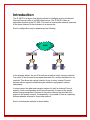
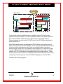
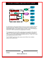
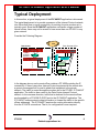
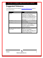
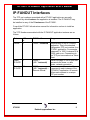
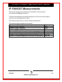
IP-FANOUT
Virtual Network Application
User’s Manual
Version 2001.2
Angel Gomez
721 Route 202-206
Bridgewater, NJ 08807
fax: 908.218.1736
phone: 908.218.0500
email: [email protected]
http://www.datatekcorp.com
DT-6061 IP-FANOUT Application User's Manual
CONTENTS
INTRODUCTION.........................................................................................................................................................3
TYPICAL DEPLOYMENT........................................................................................................................................6
IP-FANOUT FEATURES ...........................................................................................................................................7
SUGGESTED REFERENCE......................................................................................................................................8
IP-FANOUT INTERFACES .......................................................................................................................................9
IP-FANOUT COMMAND SET...............................................................................................................................10
IP-FANOUT MEASUREMENTS ...........................................................................................................................15
WARRANTY.................................................................................................................................................................16
07/06/01
2
Datatek Applications Inc.
Introduction
The IP-GATE is a device that which provides for intelligent routing of selected
Internet Protocol traffic on a WAN infrastructure. The IP-GATE is also an
embedded function of the DT-4000. The intent is to extend the network presence
of the home Internet Protocol network to a remote site.
Such a configuration may be depicted as the following:
WAN
IP-GATE
IP-GATE
IP
IP
In the diagram above, the two IP clouds are actually a single cohesive network.
The notion of a sub-network and separate masks for a remote installation is not
required. This allows the remote location of one or many Internet Protocol
devices without regard to establishing an address to geographic location
relationship.
In some cases, the wide area transport network is itself an Internet Protocol
network. Such a configuration would provide security for users of the private
network being transported. Devices on the public network may blocked from
access to the private network. Consequently, it is possible to have a completely
different address scheme for the private network.
Such a virtual private network is shown below:
DT-6061 IP-FANOUT Application User's Manual
Public IP
Home Office
Each Remote Office
DT-4000
10/100 BaseT
HUB
IP
HUB
DT-4000
DT-4000
10BaseT
DT-4000
Equipment
Sync/Async
10/100 BaseT
Sync/Async
Equipment
Contacts
DT-9001
In the private network established above, a public Internet Protocol service
network is used for transport. The only addresses visible on the public network is
that of the DT-4000s which interface to that network. The private Internet
Protocol network is routed on the IP-GATE ports of the DT-4000s individually to
each remote office.
Most WAN infrastructures use transparent HDLC framing, and support point to
point connections with IP-GATE devices. In fact, using a public IP network results
in point to point connections as well. There are a large number of situations
where a single “home office” is required to export portions of its network to many
“remote” offices. Further, the “home” location may wish to use a one or a small
number of IP-GATE interfaces to accomplish the virtual private network. When
such a situation occurs, there is an additional component that allows one to many
connectivity. That component is the IP-FANOUT application to the DT-6061.
Consider the following diagram:
07/06/01
4
Datatek Applications Inc.
DT-6061 IP-FANOUT Application User's Manual
Remote
Office
Data Center
IP WAN
DT-6061
With
IP-FANOUT
Application
DT-4000
Remote
Office
10/100 BaseT
HUB
IP
M
O
D
E
M
DK/BNS
Remote
Office
M
O
D
E
M
DT-4000
Remote
Office
TDM
Remote
Office
Remote
Office
As depicted above, the private network can use one or more completely different
network technologies. Mediation between an Internet Protocol network and an
Datakit/BNS network is accomplished either by a UMI or a pair of DT-4000 ports
when the DT-4000 is simultaneously supporting both networks.
The equipment in the remote office remains the same regardless of the network
used. A DT-4000 directly supports a Datakit/BNS network without mediation. A
TDM connection merely requires the terminating modem set. Finally, the IP WAN
may terminate directly on the DT-4000.
The IP-FANOUT application allows many remote offices to be a cohesive
network with the data center.
07/06/01
5
Datatek Applications Inc.
DT-6061 IP-FANOUT Application User's Manual
Typical Deployment
In this section, a typical deployment of the IP-FANOUT application is discussed.
The typical deployment is to provide a presence of the Internet Protocol network
into offices that have no such connectivity. An existing four-wire modem set is
typically used. Since the IP-FANOUT application can handle a large number of
remote offices, there may not be a need to have more than one DT-6061 in any
given network.
Consider the Following Diagram:
TDM
Data Center
Each Remote Office
DT-6061
With
IP-FANOUT
Application
DT-4000
10/100 BaseT
HUB
DT-4000
IP
M
O
D
E
M
M
O
D
E
M
DT-4000
M
O
D
E
M
HUB
Sync/Async
Equipment
Equipment
In the diagram above, each remote office contains a DT-4000 providing the IP
connectivity. If there is any other Internet Protocol equipment at the remote site,
a generic unmanaged hub is used to attach that equipment to the private
network. The traffic is routed through the modem set to the DT-6061 IP-FANOUT
application. The traffic is then routed to the Data Center Internet Protocol
network. In the converse direction, traffic that is destined for the remote offices
are forwarded by a DT-4000 IP-GATE port to the IP-FANOUT application. The
IP-FANOUT uses acquired routing information to forward the traffic to the specific
offices addressed. The IP-FANOUT acquires the routing information directly
from the IP-GATE connections. That is, no configuration is ever required.
07/06/01
6
Datatek Applications Inc.
DT-6061 IP-FANOUT Application User's Manual
IP-FANOUT Features
This section defines the features of the IP-FANOUT application. This is done as
a list, but some features require further elaboration.
•
•
•
•
•
Up to 64 remote offices per instance of the IP-FANOUT application.
One Data Center per instance of the IP-FANOUT application.
Up to 30 instances of the IP-FANOUT application may be present on the
same DT-6061.
1 Configuration Console is available to be used by the IP-FANOUT
administrator for diagnostic and measurement purposes.
The IP-FANOUT application is self-configuring and does not require any initial
setup information.
07/06/01
7
Datatek Applications Inc.
DT-6061 IP-FANOUT Application User's Manual
Suggested Reference
The following documents are resident at http://www.datatekcorp.com under the
documentation button.
Document
DT-6061 Platform User’s
Manual.
IP-GATE User’s Manual
DT-4000 User’s Manual.
DT-6061 Redundant Operation
White Paper.
Scope
Describes the DT-6061 Embedded
Network Processor infrastructure and
command set. This includes
configuration information, hardware
specifications, and SNMP MIB support.
The DT-6061 is the infrastructure on
which the Virtual Console application
shall reside.
Describes the stand-alone IP-GATE
interface device.
Describes the DT-4000 multi-protocol
access device. The DT-4000 is used as
the interface for physical serial
connections, and for the IP-GATE
interface connections.
Describes the method of operating the
DT-6061 in a 1+1 sparing
configuration. Note: This paper is not
posted on the above site. Contact the
author for a copy via email.
07/06/01
8
Datatek Applications Inc.
DT-6061 IP-FANOUT Application User's Manual
IP-FANOUT Interfaces
The TCP port numbers associated with a DT-6061 application are normally
referenced by which instance the application is installed. The IP-FANOUT may
be installed on any of the 30 instances of the DT-6061.
Consult the DT-6061 infrastructure manual for information on how to install an
application.
The TCP Numbers associated with the IP-FANOUT application instance are as
follows:
Set
#Channel
s
1
TCP Port#
Usage
10000 + Instance#
Home
IP-GATE
1
30000 +
(200 * Instance#)
Remote
IP-GATE
64
30000 +
(200 * Instance#) +
Remote Office#.
Administration of the IP-FANOUT
application. This is the standard
configuration TCP port number for a
DT-6061 application. For example,
instance #1 is 10001, instance #2 is
10002, and so on. Connections to
this TCP port are made via a Telnet
client.
There is a single IP-GATE port that
represents the home, or data
center, network connection.
There are up to 64 remote offices
supported on each instance of the
IP-FANOUT application. All remote
offices each connect to a unique
TCP port number.
OA&M
07/06/01
9
Datatek Applications Inc.
DT-6061 IP-FANOUT Application User's Manual
IP-FANOUT Command Set
Input Conventions
All parameters may be given on the command line. Parameters of the form
name=<value> may be given in any order.
For several complex commands, listed below, missing parameters, or corrections
of errors in given parameters, of the form name=<value> are collected by
prompting the console user. The user responds to a prompt for the name by
typing the required <value> followed by newline. Defaults are supplied in some
cases, so the user need only enter newline.
Commands may be entered in upper or lower case.
Parameters of the form name=value may use upper or lower case for name.
Default values, if any, are shown in parenthesis as part of the prompt.
Case is not preserved for values. Backspace erases one character.
Login
Syntax: login PASSWD=<password>
The login command is used to allow access to the other configuration
commands.
The login command is only visible when the application is in the logged out (i.e.
secure) mode. The unit enters this mode whenever a logout command is issued
or when the Telnet to the application instance OA&M TCP port is interrupted for
any reason.
The password is not echo-suppressed. The password consists of up to seven
alphanumeric characters. Special characters are not allowed.
The default password is “initial”.
Logout
Syntax: logout
The logout command is only allowed if the console user is logged in. It uses no
arguments. It will set the console to the logged out mode.
07/06/01
10
Datatek Applications Inc.
DT-6061 IP-FANOUT Application User's Manual
Change Password
Syntax: chgpass PASSWD=<old> NEWPASS=<new> CONFIRM=<new>
The chgpass command is used to change a user password on the system
console. The command is only allowed if the user is logged in.
All three parameters must be given on the same line as the command. None of
those entries are echo-suppressed.
If the current password is valid, and the two entries for the new password match,
the password is changed to the new value.
Help
Syntax: help |? [Command]
The help command is always visible. The help command displays the currently
allowed commands for the mode that the unit is currently entered. The alternate
command for help is a question mark.
Version
Syntax: ver
The version command is only visible when the application is logged in. The
command has no arguments. It displays the current software and database
revisions of the application.
Verify of Configuration
Syntax: vfy
The vfy command is only visible when the application is logged in. The command
is used to verify the parameters of the IP-FANOUT instance such as the instance
number, the IP address of the DT-6061, and other relevant information.
Display of Measurements
07/06/01
11
Datatek Applications Inc.
DT-6061 IP-FANOUT Application User's Manual
Syntax: dmeas < ALL | HOME | RMT <RANGE> >
The dmeas command is only visible when the application is logged in. The
command is used to display the current measurements on any of the interfaces.
The dmeas command may display the measurements for a single interface, or all
of the interfaces. Where the value of <RANGE> is specified, the identifier may be
a single numeric (e.g. the number ‘3’), a numeric range (e.g. ‘1-3’), or the value
ALL’ to indicate the entire allowed numeric range.
The dmeas command will display all connections with a target of ALL. Only the
home site IP-GATE connection is displayed with a target of HOME. For remote
site IP-GATE connections, the target of RMT is used with a range of connections.
When measurements are displayed via the dmeas command, and more than a
single entity has been specified; only non-zero entries are actually displayed.
Displaying Current Connections
Syntax: dc
The dconn command is used to display all of the current connections into the IPFANOUT application.
Please note that the command does not require any arguments. The command
will issue a report that shows the connection peer for each active connection.
Snooping on Traffic
Syntax: snoop [ OFF | ALL | HOME | RMT < ALL | <Range> > ]
[ VERBOSE ]
The IP-FANOUT application has a diagnostic ability to snoop on any of interfaces
which carry data. This is done with the snoop command. All output is directed to
the OA&M connection.
If the command is invoked with no arguments, it produces a report of all active
snooper configurations.
If the command is invoked with the OFF option, all of the active snooper
configurations are disabled.
07/06/01
12
Datatek Applications Inc.
DT-6061 IP-FANOUT Application User's Manual
If the command is invoked with the ALL option, the IP-GATE connections to the
home site and every remote site is simultaneously enabled.
If the command is invoked with the HOME option, the IP-GATE connection to the
home network is snooped.
If the command is invoked with the RMT <Range> option, the IP-GATE
connection to the remote site(s) specified is snooped. A <Range> may be a
single remote site (e.g. 3), a set of remote sites (e.g. 3-5), or all remote sites (i.e.
all).
The command also takes an optional argument for verbose operation. When the
snooper operates in verbose mode, the IP header checksum is verified. Should
the packet be of the TCP protocol, the TCP header is verified, and the contents
of TCP packet are decoded and displayed including any data.
Clear Measurements
Syntax: clr < ALL | HOME | RMT <RANGE> >
The measurements displayed with the dmeas command are aggregated until
cleared. The clear command will set measurements to zero. When the target is
ALL, both the home site and all of the remote site IP-GATE connection
measurements are cleared. When the target is HOME, only the home site IPGATE measurements are cleared. When the target is RMT, a range of remote
sites indicates which IP-GATE connections are to have the measurements
cleared.
Prompt Labels
Syntax: label [ word (no spaces) | NONE ]
The prompt on the application console may be customized with a label up to
eight characters in length. The value of none deletes any existing label on the
prompt. The current configuration is displayed during a verify configuration, by
invoking the label command without arguments, or merely by the prompt display.
07/06/01
13
Datatek Applications Inc.
DT-6061 IP-FANOUT Application User's Manual
Application Comments
Syntax: comment [ L1=”Any Comment”]
[ L2=”Any Comment”]
[ L3=”Any Comment”]
The IP-FANOUT application may have comments which are displayed with the
verify configuration command. Up to three lines of comments are available. Each
line may have a comment up to 64 characters in length. Each comment is double
quoted to allow for spaces to be embedded. A comment with no characters (i.e.
“”) is used to delete a comment which is not desired. It is not necessary to delete
prior to adding a new comment. The new comment shall replace the existing
comment at the line specified.
07/06/01
14
Datatek Applications Inc.
DT-6061 IP-FANOUT Application User's Manual
IP-FANOUT Measurements
This section itemizes the measurements available using the display
measurements (dmeas) command.
The base measurements are always displayed, and the error and exception
counters are only displayed if nonzero.
The measurements are per console, and per administrator.
The measurements available are as follows:
Measurement Description
Number of Bytes Received
Number of Bytes Transmitted
Number of IP Packets Received
Number of IP Packets Transmitted
Number of Route Requests Sent to a Remote IP-GATE
Number of Route Responses received from a remote IP-GATE
Number of Packets dropped due to flow control in the network.
07/06/01
Type
Base
Base
Base
Base
Non-Zero
Non-Zero
Non-Zero
15
Datatek Applications Inc.
DT-6061 IP-FANOUT Application User's Manual
Warranty
The warranty period for hardware shall be one year from the date of delivery, and
the warranty for software shall be 90 days from the date of delivery.
Replacements and repairs are guaranteed for the longer of the remaining original
warranty period or 90 days.
Author: Angel Gomez , Phd.
[email protected]
[email protected]
©Copyright 2001 TeleComp Inc.
All Rights Reserved
Printed in USA
07/06/01
16
Datatek Applications Inc.