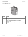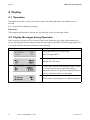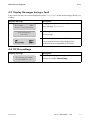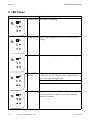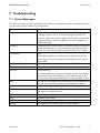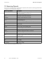
1
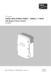
PV Inverter
SUNNY MINI CENTRAL
9000TL/10000TL/11000TL
9000TL/10000TL/11000TL with Reactive Power Control
User Manual
SMC9-11TLRP-BA-BEN111320 | TBEN-SMC9-11TL | Version 2.0
EN
SMA Solar Technology AG
Table of Contents
Table of Contents
1
1.1
1.2
1.3
1.4
Information on this Manual. . . . . . . . . . . . . . . . . . . . . . . . .
Validity . . . . . . . . . . . . . . . . . . . . . . . . . . . . . . . . . . . . . . . . . . . .
Target Group . . . . . . . . . . . . . . . . . . . . . . . . . . . . . . . . . . . . . . .
Additional Information . . . . . . . . . . . . . . . . . . . . . . . . . . . . . . . .
Symbols Used . . . . . . . . . . . . . . . . . . . . . . . . . . . . . . . . . . . . . . .
5
5
5
5
6
2
2.1
2.2
2.3
Safety . . . . . . . . . . . . . . . . . . . . . . . . . . . . . . . . . . . . . . . . . .
Appropriate Usage . . . . . . . . . . . . . . . . . . . . . . . . . . . . . . . . . . .
Safety Instructions . . . . . . . . . . . . . . . . . . . . . . . . . . . . . . . . . . . .
Explanation of Symbols . . . . . . . . . . . . . . . . . . . . . . . . . . . . . . .
7
7
8
9
2.3.1
Symbols on the Inverter. . . . . . . . . . . . . . . . . . . . . . . . . . . . . . . . . . . . . . . . . . .9
2.3.2
Symbols on the Type Label . . . . . . . . . . . . . . . . . . . . . . . . . . . . . . . . . . . . . . . .9
3
Product Overview . . . . . . . . . . . . . . . . . . . . . . . . . . . . . . . 11
4
4.1
Display . . . . . . . . . . . . . . . . . . . . . . . . . . . . . . . . . . . . . . . . 12
Operation . . . . . . . . . . . . . . . . . . . . . . . . . . . . . . . . . . . . . . . . . 12
4.2
4.3
4.4
Display Messages during Operation . . . . . . . . . . . . . . . . . . . . 12
Display Messages during a Fault . . . . . . . . . . . . . . . . . . . . . . . 13
DC Overvoltage . . . . . . . . . . . . . . . . . . . . . . . . . . . . . . . . . . . . 13
5
LED States . . . . . . . . . . . . . . . . . . . . . . . . . . . . . . . . . . . . . . 14
6
Visual Check and Cleaning . . . . . . . . . . . . . . . . . . . . . . . . 16
7
7.1
Troubleshooting . . . . . . . . . . . . . . . . . . . . . . . . . . . . . . . . . 17
Status Messages . . . . . . . . . . . . . . . . . . . . . . . . . . . . . . . . . . . . 17
7.2
Measuring Channels. . . . . . . . . . . . . . . . . . . . . . . . . . . . . . . . . 18
8
Glossary . . . . . . . . . . . . . . . . . . . . . . . . . . . . . . . . . . . . . . . 19
9
Contact . . . . . . . . . . . . . . . . . . . . . . . . . . . . . . . . . . . . . . . . 20
User Manual
SMC9-11TLRP-BA-BEN111320
3
Table of Contents
4
SMC9-11TLRP-BA-BEN111320
SMA Solar Technology AG
User Manual
SMA Solar Technology AG
Information on this Manual
1 Information on this Manual
1.1 Validity
This manual applies to the following device types:
• Sunny Mini Central 9000TL (SMC 9000TL-10)
• Sunny Mini Central 10000TL (SMC 10000TL-10)
• Sunny Mini Central 11000TL (SMC 11000TL-10)
• Sunny Mini Central 9000TL with Reactive Power Control (SMC 9000TLRP-10)
• Sunny Mini Central 10000TL with Reactive Power Control (SMC 10000TLRP-10)
• Sunny Mini Central 11000TL with Reactive Power Control (SMC 11000TLRP-10)
1.2 Target Group
This manual is for the operator.
1.3 Additional Information
You will find additional information on the device-specific technical data in the installation guide
provided.
You will find additional information on special subjects (e.g. description of the operating parameters)
in the download area at www.SMA.de/en.
User Manual
SMC9-11TLRP-BA-BEN111320
5
Information on this Manual
SMA Solar Technology AG
1.4 Symbols Used
The following types of safety instructions and general information are used in this manual:
DANGER!
DANGER indicates a hazardous situation which, if not avoided, will result in death or
serious injury.
WARNING!
WARNING indicates a hazardous situation which, if not avoided, could result in death or
serious injury.
CAUTION!
CAUTION indicates a hazardous situation which, if not avoided, could result in minor or
moderate injury.
NOTICE!
NOTICE indicates a situation that can result in property damage if not avoided.
Information
Information provides tips that are valuable for the optimal installation and operation of
your product.
6
SMC9-11TLRP-BA-BEN111320
User Manual
SMA Solar Technology AG
Safety
2 Safety
2.1 Appropriate Usage
The Sunny Mini Central is a PV inverter, which converts the direct current of the PV array to alternating
current and feeds it into the power distribution grid.
Operating Principle of a PV Plant with Sunny Mini Central
The Sunny Mini Central may only be operated with PV arrays (modules and cabling) of protection
class II. Do not connect any sources of energy other than PV modules to the Sunny Mini Central.
Do not use the Sunny Mini Central for purposes other than those described here. Alternative uses,
modifications to the Sunny Mini Central or the installation of components not expressly recommended
or sold by SMA Solar Technology AG void the warranty claims and operation permission. Contact
the SMA Serviceline if you need clarification regarding proper use of the inverter.
This manual is a part of the Sunny Mini Central. Observe all of the activities described in this manual.
Keep this manual in a convenient place for future reference.
User Manual
SMC9-11TLRP-BA-BEN111320
7
Safety
SMA Solar Technology AG
2.2 Safety Instructions
DANGER!
Electric shock caused by high voltage in the inverter.
Even when no external voltage is present, there can still be high voltages in the device.
• Electrical installation, repairs and modification may be carried out by qualified
personnel only.
• The appliance is not to be used by children or persons with reduced physical, sensory
or mental capabilities, or lack of experience and knowledge, unless they have
beengiven supervision or instruction.
• Children should be supervised to ensure that they do not play with the appliance.
CAUTION!
Danger of burn injury due to hot enclosure parts.
• Only touch the lid and display during operation.
NOTICE!
Damage to the inverter through overvoltage, if the yellow LED flashes 4 times.
• Inform your installer immediately if the yellow LED flashes and the inverter shows the
display message "!PV-Overvoltage! !DISCONNECT DC!".
8
SMC9-11TLRP-BA-BEN111320
User Manual
SMA Solar Technology AG
Safety
2.3 Explanation of Symbols
2.3.1 Symbols on the Inverter
Symbol
Explanation
Operation display.
Ground fault or varistor defective. Inform your installer.
An error has occurred. Inform your installer immediately.
You can operate the display by tapping.
Tap once:
The background illumination switches on or the display scrolls one
message further.
2.3.2 Symbols on the Type Label
Symbol
Explanation
Beware of dangerous electrical voltage.
The inverter operates at high voltages. All work on the inverter may only be
carried out by electrically skilled persons.
Beware of hot surface.
The inverter can become hot during operation. Avoid contact during
operation.
Observe all documentation that accompanies the inverter.
The inverter must not be disposed of together with household waste. Further
disposal information can be found in the installation guide provided.
CE mark.
The inverter complies with the requirements of the applicable EC
guidelines.
User Manual
SMC9-11TLRP-BA-BEN111320
9
Safety
Symbol
SMA Solar Technology AG
Explanation
The inverter is transformerless.
Direct current (DC).
Alternating current (AC).
Degree of protection IP65.
The inverter is protected against penetration by dust particles and water
jets from any angle.
RAL quality mark for solar products.
The inverter complies with the requirements of the German Institute for
Quality Assurance and Labeling.
Australian mark of conformity.
The inverter complies with the requirements of the applicable Australian
guidelines.
Korean mark of conformity.
The inverter complies with the requirements of the applicable Korean
guidelines.
Chinese mark of conformity.
The inverter complies with the requirements of the applicable Chinese
guidelines.
10
SMC9-11TLRP-BA-BEN111320
User Manual
SMA Solar Technology AG
Product Overview
3 Product Overview
Position
A
B
C
Description
Display
Lid
LEDs
Green LED = Operation
Red LED = ground fault; varistor defective or string fuse defective
D
E
User Manual
Yellow LED = Fault
Fan screen
Type label for the identification of the inverter via the serial number (Serial No.).
SMC9-11TLRP-BA-BEN111320
11
Display
SMA Solar Technology AG
4 Display
4.1 Operation
The display shows the current values of your plant. The displayed values are updated every 5
seconds.
You can operate the display by tapping.
Tap once:
The background illumination switches on or the display scrolls one message further.
4.2 Display Messages during Operation
Upon error-free connection of the inverter to the power distribution grid, after approximately one
minute, the display starts alternating between the messages shown below. Each message appears for
5 seconds, and then the cycle restarts from the beginning.
Display message
E-today
Mode
0Wh
MPP
Description
Energy generated on the current day
Status message "MPP"
Current feed-in power
Voltage of the PV array
In Sunny Mini Centrals with Reactive Power Control,
the current reactive power value Qac and the
displacement factor cos φ (PF) are displayed after a
further 5 seconds or when you tap again.
Energy produced so far
Total number of operating hours in feed-in operation
12
SMC9-11TLRP-BA-BEN111320
User Manual
SMA Solar Technology AG
Display
4.3 Display Messages during a Fault
In the event of a fault, the inverter displays the status "Disturbance" and a fault message. Inform your
installer.
Display message
E-today
0Wh
Mode Disturbance
Disturbance
Vac-Bfr
Description
Energy generated on the current day
Status message "Disturbance"
Operating state
Fault message
Measured value at the time of the fault
Current measured value (only displayed if a
measured value is responsible for the fault)
4.4 DC Overvoltage
Display message
!PV-Overvoltage!
!DISCONNECT DC!
User Manual
Description
The DC input voltage is too high at the inverter.
Inform your installer immediately!
SMC9-11TLRP-BA-BEN111320
13
LED States
SMA Solar Technology AG
5 LED States
Status
Description
All LEDs are on The inverter is initializing.
All LEDs are off The DC input voltage at the inverter is too low for grid
feeding.
Green LED on The inverter is feeding in to the power distribution grid.
14
Green LED
flashing
The inverter is monitoring the power distribution grid and
is waiting for the DC voltage to reach a defined limit so
that it can begin feeding the grid.
Operation interrupted.
Power limitation in the inverter.
Red LED on
A ground fault has occurred or one of the thermally
monitored varistors on the DC input side is defective.
Inform your installer.
SMC9-11TLRP-BA-BEN111320
User Manual
SMA Solar Technology AG
LED States
Status
Red LED
flashing
Description
This fault can be caused by either of the following:
At least one of the varistors is defective: display message
<Check Varistor>.
At least one string fuse is defective: display message
<DC fuse>
In both cases the inverter continues feeding into the grid.
Inform your installer.
Yellow LED on The inverter has switched to the operating state
"Dauerhafte Betriebshemmung" (Permanent Shutdown).
This can have several causes. Inform your installer.
Yellow LED
flashing
User Manual
The inverter displays a fault. This can have several causes.
Inform your installer.
SMC9-11TLRP-BA-BEN111320
15
Visual Check and Cleaning
SMA Solar Technology AG
6 Visual Check and Cleaning
Check the inverter and cables for any visual signs of external damage. Contact your installer if you
find any damage. Do not perform any repair work yourself.
Ask your installer to check for correct inverter operation at regular intervals.
16
SMC9-11TLRP-BA-BEN111320
User Manual
SMA Solar Technology AG
Troubleshooting
7 Troubleshooting
7.1 Status Messages
Your inverter can be in various operating states. These are displayed as status messages, which can
vary according to the method of communication.
Message
Balanced
Disturbance
Description
The inverter has disconnected from the power distribution grid or
is limiting its power over a 10 minute average to 5 kVA. The
inverter is a part of a 3 phase system with 2 further inverters and
equipped with the SMA Power Balancer for the avoidance of
unbalanced loads.
Overtemperature in the inverter. The inverter reduces its output to
prevent overheating. To avoid unnecessary yield penalties, the
design of the PV plant should be checked. Inform your installer.
Fault.
Earthfault/Riso
Error
grid mon.
This message appears for safety reasons and ensures that the
inverter does not connect to the power distribution grid. Inform
your installer.
Measurement of the insulation resistance of the PV plant.
An error has been detected. Inform your installer.
Grid monitoring
Derating
MPP
Mpp-Search
Off Grid
Offset
Stop
V-Const
waiting
User Manual
This display appears during the start phase, before the inverter is
connected to the power distribution grid, predominantly in the
morning and evening when radiation is too low and after an error.
The inverter is operating in MPP mode. MPP is the standard display
message when operating under normal radiation conditions.
The inverter is calculating the MPP.
The inverter is in Island mode. This mode is specially designed for
operation in an off-grid system.
Offset adjustment of the measurement electronics.
Operation interrupted.
Constant voltage operation.
The conditions for connecting are not (yet) fulfilled.
SMC9-11TLRP-BA-BEN111320
17
Troubleshooting
SMA Solar Technology AG
7.2 Measuring Channels
If your inverter is equipped with a communication component, then numerous measuring channels and
messages can be transmitted for diagnostics.
Measuring channel
Balancer
E-total
Error
Event-Cnt
Fac
h-On
h-total
Iac
Ipv
Is*
Mode
Pac
PF*
Phase
Power On
Qac*
Riso
Sac*
Serial Number
Vac
Vpv
Vpv-Setpoint
Description
Displays the current operating mode of the inverter that is set to the
operating parameter "PowerBalancer".
Total amount of energy fed in
Identification of the current fault/error
Number of events that have occurred
Power line frequency
Total operating hours
Total number of operating hours in feed-in operation
Power line current
Direct current
Apparent current
Display of the current operating state.
Generated AC power
Displacement factor cos φ
The phase to which the inverter is connected.
Total number of grid connections
Reactive power
Insulation resistance of the PV plant before entering into the power
distribution grid.
Apparent power
Serial number of inverter
Line voltage
PV input voltage
PV setpoint voltage
* Only for Sunny Mini Central with Reactive Power Control
18
SMC9-11TLRP-BA-BEN111320
User Manual
SMA Solar Technology AG
Glossary
8 Glossary
AC
Abbreviation for "alternating current".
DC
Abbreviation for "direct current".
Derating
A controlled reduction in performance, usually dependent on component temperatures.
Electronic Solar Switch (ESS)
The Electronic Solar Switch is part of the DC disconnection unit of the inverter. The Electronic Solar
Switch must be securely inserted into the bottom of the inverter and must only be removed by an
electrically skilled person.
MPP (Maximum Power Point)
Operating point of the inverter from current/voltage of the PV array. The actual position of the MPP
changes constantly, depending on the level of radiation and cell temperature.
PV
Abbreviation for "photovoltaics".
Reactive Power Control
Inverters with Reactive Power Control are inverters capable of utilizing reactive power. By setting a
default value for the displacement factor (cos φ), they can feed reactive power to the grid.
SMA Power Balancer
The SMA Power Balancer is a serial feature of the Sunny Mini Central. The SMA Power Balancer
prevents the formation of an unbalanced load > 5 kVA (in Italy > 6 kVA) during 3-phase feed-in. To
this effect, 3 Sunny Mini Centrals are connected via a control line to a 3-phase feed-in unit.
Unbalanced load
The unbalanced load is the difference between the power fed into the grid at the individual phase
conductors. In Germany, this must not exceed 5 kVA. In Italy, the unbalanced load is restricted to
6 kVA.
Varistor
The varistors protect the electronics in the inverter from atmospherically coupled energy peaks, such
as those that can occur when lightning strikes nearby.
User Manual
SMC9-11TLRP-BA-BEN111320
19
Contact
SMA Solar Technology AG
9 Contact
If you have technical problems, first contact your installer. The following information is required in
order to provide you with the necessary assistance:
• Inverter device type
• Serial number of inverter
• Type and number of PV modules connected
• Blink code or display message of the inverter
• Optional equipment (e.g. communication devices)
SMA Solar Technology AG
Sonnenallee 1
34266 Niestetal, Germany
www.SMA.de
SMA Serviceline
Inverters:
+49 561 9522 1499
Communication:
+49 561 9522 2499
Fax:
+49 561 9522 4699
E-Mail:
[email protected]
20
SMC9-11TLRP-BA-BEN111320
User Manual
SMA Solar Technology AG
User Manual
Contact
SMC9-11TLRP-BA-BEN111320
21
Contact
22
SMA Solar Technology AG
SMC9-11TLRP-BA-BEN111320
User Manual
SMA Solar Technology AG
Legal Restrictions
The information contained in this document is the property of SMA Solar Technology AG. Publishing its content, either partially or
in full, requires the written permission of SMA Solar Technology AG. Any internal company copying of the document for the
purposes of evaluating the product or its correct implementation is allowed and does not require permission.
Exclusion of liability
The general terms and conditions of delivery of SMA Solar Technology AG shall apply.
The content of these documents is continually checked and amended, where necessary. However, discrepancies cannot be
excluded. No guarantee is made for the completeness of these documents. The latest version is available online at www.SMA.de
or from the usual sales channels.
Guarantee or liability claims for damages of any kind are excluded if they are caused by one or more of the following:
• Damages during transportation
• Improper or inappropriate use of the product
• Operating the product in an unintended environment
• Operating the product whilst ignoring relevant, statutory safety regulations in the deployment location
• Ignoring safety warnings and instructions contained in all documents relevant to the product
• Operating the product under incorrect safety or protection conditions
• Altering the product or supplied software without authority
• The product malfunctions due to operating attached or neighboring devices beyond statutory limit values
• In case of unforeseen calamity or force majeure
The use of supplied software produced by SMA Solar Technology AG is subject to the following conditions:
• SMA Solar Technology AG rejects any liability for direct or indirect damages arising from the use of software developed by
SMA Solar Technology AG. This also applies to the provision or non-provision of support activities.
• Supplied software not developed by SMA Solar Technology AG is subject to the respective licensing and liability agreements
of the manufacturer.
SMA Factory Warranty
The current guarantee conditions come enclosed with your device. These are also available online at www.SMA.de and can be
downloaded or are available on paper from the usual sales channels if required.
Trademarks
All trademarks are recognized even if these are not marked separately. Missing designations do not mean that a product or brand
is not a registered trademark.
The Bluetooth® word mark and logos are registered trademarks owned by Bluetooth SIG, Inc. and any use of such marks by SMA
Solar Technology AG is under license.
SMA Solar Technology AG
Sonnenallee 1
34266 Niestetal
Germany
Tel. +49 561 9522-0
Fax +49 561 9522-100
www.SMA.de
E-Mail: [email protected]
© 2004 to 2011 SMA Solar Technology AG. All rights reserved
User Manual
SMC9-11TLRP-BA-BEN111320
23
4."4PMBS5FDIOPMPHZ"(
XXX4."EF