1
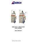
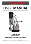
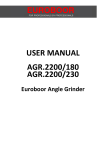
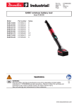
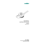
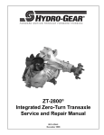
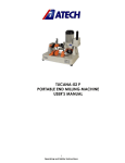
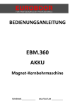
EUROBOOR
FOR PROFESSIONALS BY PROFESSIONALS
USER MANUAL
ECO.50-T
Magnetic Drilling Machine
SERIAL NO.____________
DATE OF PURCHASE __________
Congratulations on your purchase of the Euroboor ECO.50-T Portable Magnetic Drilling Machine.
Your model is designed to produce superior holes quickly and efficiently. Through years of
experience, constant innovation and development, Euroboor BV is committed to provide you with
metal cutting tools and products to help you be more productive.
Before operating your new magnetic drilling machine, please read all instructions first. These include
the Operator’s Manual and Warning Label on the unit itself. With proper use, care, and
maintenance, your
model will provide you with years of effective hole drilling performance.
TO REDUCE THE RISK OF INJURY USER MUST READ AND UNDERSTAND ALL INSTRUCTIONS
EUROBOOR BV
Kryptonstraat 110
2718 TD Zoetermeer
Netherlands
T +31 79 361 49 90
F +31 79 361 49 89
[email protected]
www.euroboor.com
ISSUE 1/Original version/OCT 2013
2
Fig. 1
ISSUE 1/Original version/OCT 2013
3
Symbol
Term, meaning
Explanation
Read documentation
Be absolutely sure to read the enclosed
documentation such as the Instruction Manual and
the General Safety Instructions.
Wear ear protection
Use ear protection during operation.
Wear eye protection
Use eye-protection during operation.
Danger/warning/caution
Observe the information in the adjacent text!
European conformity symbol
Confirms the conformity of the power tool with
the directives of the European Community.
Product with basic insulation and exposed
(touchable), conductive parts additionally
connected to the protective earth conductor.
Class of protection I
mm
Millimeter
Unit of measure for length, width, height or depth
kg
Kilogram
Unit of measure for the mass
V
Volt
Unit of measure for the electric voltage
A
Ampere
Unit of measure for the electric current intensity
W
Watt
Unit of measure for the output
N
Newton
Unit of measure for the force
min
Minutes
Unit of measure for the time
no
No-load speed
Revolution speed at no-load
1/min
per minute
Unit of measure for number of revolutions,
strokes, impacts or oscillations per minute.
GENERAL POWER TOOL SAFETY WARNINGS
ISSUE 1/Original version/OCT 2013
4
Do not use this power tool before you have thoroughly read and completely understood this
Instruction Manual and the “General Safety Instructions”, including the figures, specifications, safety
regulations and the signs indicating DANGER, WARNING and CAUTION.
WARNING: When using electrical tools basic safety precautions should always be followed to
reduce the risk of fire, electrical shock and personal injury including following.
Please also observe the relevant national industrial safety regulations. Non-observance of the safety
instructions in the said documentation can lead to an electric shock, burns and/or severe injuries.
This Operator’s Manual and the “General Safety Instructions” should be kept for later use and
enclosed with the power tool, should it be passed on or sold.
WORK AREA
1. Keep your work area clean and well lit. Cluttered benches and dark areas invite accidents.
2. Do not operate magnetic drilling machine in explosive atmospheres, such as in the presence
of flammable liquids, gases or dust. Magnetic drilling machine may create sparks which may
ignite the dust or fumes.
3. Keep bystanders, children, and visitors away while operating a magnetic drilling machine.
Distractions can cause you to lose control.
ELECTRICAL SAFETY
1. Magnetic drilling machine plugs must match the outlet. Never modify the plug in any way. Do
not us any adapter plugs.
2. Avoid body contact with grounded surfaces such as pipes, radiators, ranges and refrigerators.
There is an increased risk of electric shock if your body is grounded.
3. Do not expose magnetic drilling machines to rain or wet conditions. Water entering a
machine will increase the risk of electric shock.
4. Do not abuse the cord. Never use the cord to carry the magnetic drilling machine or pull the
plug from an outlet. Keep cord away from heat, oil, sharp edges or moving parts. Replace
damaged cords immediately. Damaged cords increase the risk of electric shock.
5. When operating a magnetic drilling machine, use an extension cord suitable for outdoor use.
Use of a cord suitable for outdoor use reduces the risk of electric shock.
6. If operating a magnetic drilling machine in a damp location is unavoidable, use a residual
current device (RCD) protected supply. Use of an RCD reduces the risk of electric shock.
PERSONAL SAFETY
1. Stay alert, watch what you are doing and use common sense when using a magnetic drilling
machine. Do not use machine while tired or under the influence of drugs, alcohol, or
medication. A moment of inattention while operating magnetic drilling machines may result
in serious personal injury.
2. Dress properly. Do not wear loose clothing or jewelry. Contain long hair. Keep your hair,
clothing, and gloves away from moving parts. Loose clothes, jewelry, or long hair can be
caught in moving parts.
3. Avoid accidental starting. Be sure switch is off before plugging in. Carrying magnetic drilling
machines with your finger on the switch or plugging in magnetic drilling machines that have
the switch on invites accidents.
4. Never place hands, fingers, gloves or clothing near cutting area or rotating machine parts.
ISSUE 1/Original version/OCT 2013
5
5. Remove adjusting keys or switches before turning the machine on. A wrench or a key that is
left attached to a rotating part of the machine may result in personal injury.
6. Do not overreach. Keep proper footing and balance at all times. Proper footing and balance
enables better control of the magnetic drilling machine in unexpected situations.
7. Use safety equipment. Always wear eye protection. Dust mask, non-skid safety shoes, hard
hat, or hearing protection must be used for appropriate conditions.
8. Always use supplied safety chain during any work on non-horizontal components. Mounting
can release.
MACHINE USE AND CARE
1. When using the machine on non-horizontal surfaces, you must use cutting paste. Do not use
oil because the oil can drip into the motor unit.
2. During machine operations, the annular cutter must be cooled and lubricated with good
quality cutting or lubrication oil. Remove the slug from the annular cutter after each hole.
Caution, the slug may be hot!
3. Use clamps or other practical way to secure and support the work piece to a stable platform.
Holding the work by hand or against your body is unstable and may lead to loss of control.
4. Do not use machine if switch does not turn it on or off. Any tool that cannot be controlled
with the switch is dangerous and must be repaired.
5. Disconnect the plug from the power source before making any adjustments, changing
accessories, or storing the tool. Such preventive safety measures reduce the risk of starting
the tool accidentally.
6. Store idle Magnetic drilling machines out of reach of children and other untrained persons.
Tools are dangerous in the hands of untrained users.
7. Maintain machines with care. Keep cutting tools sharp and clean. Properly maintained tools,
with sharp cutting edges are less likely to bind and are easier to control.
8. Check for misalignment or binding of moving parts, breakage of parts, and any other
condition that may affect the machine operation. If damaged, have the tool serviced before
using. Many accidents are caused by poorly maintained tools.
9. Use only accessories that are recommended by Euroboor BV for your model. Accessories that
may be suitable for one machine, may become hazardous when used on another machine.
SERVICE
• Tool service must be performed only by qualified repair personnel. Service or maintenance
performed by unqualified personnel could result in a risk of injury.
• When servicing a tool, use only identical replacement parts. Follow instructions in the
Maintenance section of this manual. Use of unauthorized parts or failure to follow
Maintenance Instructions may create a risk of electric shock or injury.
• When using this machine, you MUST wear ear and eye protection.
ISSUE 1/Original version/OCT 2013
6
ADDITIONAL SPECIFIC SAFETY RULES FOR MAGNETIC DRILLING MACHINES
• Keep your fingers well out of the drill area;
• Avoid touching the drilled core that is automatically ejected by the centering pin when the
working procedure is finished. Contact with the core when it is hot, or if it falls, can cause
personal injuries;
• Always use the drill guard. Before turning on machine ensure the guard is closed securely;
• Always use the safety strap;
• The magnetic drilling machine is suitable for use on steel with a thickness starting from 6
mm, with zero air gap between the magnet core surface and the mounting surface.
Curvature, coats of paint and surface irregularities will create an air gap. Keep the air gap to a
minimum;
• Always place the machine on a flat surface;
• Do not clamp the magnetic drilling machine on small or irregularly shaped objects;
• Always place the machine on a surface that is clear of shavings, chips, swarf and surface dirt;
• Keep the magnet clean and free of debris and swarf;
• Do not turn on the machine until it has been mounted and installed according to these
instructions;
• Do not turn on the machine before having checked that the magnetic stand has been
tightened firmly to the mounting surface;
• Adjust the table so cutter does not extend into the work piece before drilling. Do not perform
any design, assembly or construction activities on the work piece while the machine is turned
on;
• Before turning on the machine, make sure the accessory has been mounted correctly;
• Always use the recommended speed for the accessories and the material;
• Do not use the machine on the same work piece on which electric welders are being used;
• Use only an appropriate cutting fluid. Use a general non-oil-based metal cutting coolant
diluted with water;
• Do not use liquid cutting fluids while drilling vertically or overhead. Dip the cutter in cutting
paste or apply an appropriate spray for these applications;
• Do not pour cutting fluid into the reservoir while it is mounted in the bracket. Do not allow
cutting fluid to enter the drill motor;
• Before use, ensure movable chuck guard operates properly;
• Ensure that metal chips or resinous residue cannot lead to blockage of the function;
• In case of jammed cutter disconnect the machine from the power supply, remove the reason
for the jam before turning on the machine again.
RESIDUAL RISKS
In spite of the application of the relevant safety regulations and the implementation of safety
devices, certain residual risks cannot be avoided.
These are:
• Impairment of hearing
• Risk of personal injury from flying particles
• Risk of burns due to accessories becoming hot during operation
• Risk of personal injury due to prolonged use.
ISSUE 1/Original version/OCT 2013
7
MARKINGS ON THE TOOL
The following pictograms are shown on the tool:
Read instruction manual before use.
Wear ear protection in areas with noise emissions > 80 db(A).
Wear eye protection.
POSITION Serial number
The Serial Number, which also includes the type of machine, the year and month of manufacturing
and identification number, is engraved on the frame, magnet and the motor unit.
Example:
050T 12 11 001
Model type
Year of Manufacture
Month of manufacture
Identification number
PACKAGE CONTENT
1 Magnetic drilling machine
4 Tap collets M10 DIN 376, M12 DIN 376, M14 DIN 376, M16 DIN 376
1 Carrying case
1 Drill guard
3 Handles
1 Allen Key 2.5
1 Allen Key 3
1 Allen Key 4
1 Allen Key 5
1 Wrench 8
1 Lubrication system
1 Safety chain
1 Cutting oil
1 MT 3
1 MT 3 Ejection pin
1 Operators manual
1 Exploded drawing
1 Safety Ear Protection
1 Safety Glasses
1 Safety Gloves
ISSUE 1/Original version/OCT 2013
8
TECHNICAL DATA ECO.50-T
ANNULAR CUTTERS
TWIST DRILLS
THREADING
COUNTERSINKING
LENGTH
WIDTH
HEIGHT
STROKE
WEIGHT
MAGNET (L x W x H)
MAGNETIC FORCE
MOTOR POWER
TOTAL POWER
SPEED (no load)
SPEED (load 1200W)
SPINDLE
AVAILABLE
ø 12 - 50 mm
ø 1 - 23 mm
M3 - M16
ø10 - 40 mm
245 mm
160 mm
385 - 550 mm
170 mm
14 kg
170 x 85 x 48 mm
1850 kg
1250 W
1360 W
(I) 100 - 280 minˉ¹
(II) 185 - 530 minˉ¹
(I) 250 minˉ¹
(II) 460 minˉ¹
MT 2 - 19,05 mm Weldon
110 - 120 V AC
220 - 240 V AC
Emission values for sound and vibration
(Two-figure – specifications as per ISO 4871)
Sound emission
Measured A-weighted sound power level LwA (re 1 pW), in
decibels
Measuring uncertainty KwA, in decibels
103
3
A-weighted emission pressure power level measured at the
workplace LpA (re 20 μPa), in decibels
Measuring uncertainty KpA, in decibels
103
3
Vibration emission
Rated acceleration, in m/s²
Measuring uncertainty K, in m/s²
0.5
1.5
REMARK: The sum of the measured emission value and respective measuring inaccuracy represents
the upper limit of the values that can occur during measuring.
Wear ear protection!
For measurement values obtained according to the respective product standard, see the last page of
this Instruction Manual.
ISSUE 1/Original version/OCT 2013
9
DESCRIPTION (fig. 1)
WARNING: Never modify the power tool or any part of it. Damage or personal injury could
result.
1.
2.
3.
4.
5.
6.
Safety Guard
Feed handle
Cooling system tank
Magnetic stand
Magnet switch
Motor switch
INTENDED USE
This magnetic drilling machine is intended for commercial use as a drilling machine for drilling
materials with a magnetizable surface using annular cutters and twist drills, and for tapping,
countersinking and reaming in a weather-protected environment using the application tools and
accessories recommended by EUROBOOR.
The magnetic drilling machine can be used horizontally, vertically or overhead.
INSTRUCTIONS FOR PUTTING INTO OPERATION
Please make sure that the contacting surface for the magnet is level, clean and rust-free.
Remove any varnish or primer. When working on materials that are not magnetizable, suitable
fixation devices, obtainable as accessories from EUROBOOR, e. g. suction plate, vacuum plate or
pipe-drilling device must be used.
When work on steel materials with a material thickness of less than 12 mm, the work piece must
be reinforced with an additional steel plate in order to guarantee the magnetic holding power.
Check the machine for possible damage; Before using the machine, you must carefully check
protective devices or slightly damaged components to ensure they are operating perfectly and as
intended.
Check that moving are in perfect working order and do not jam and check whether parts are
damaged. All parts must be correctly installed and fulfill all conditions necessary to ensure perfect
operation of the machine.
Damaged protective devices and parts must be repaired or replaced according to specifications by
EUROBOOR of any authorized EUROBOOR dealer.
DO NOT use under wet conditions or in presence of flammable liquids or gases. This magnetic drilling
machine is a professional power tool.
DO NOT let children come into contact with the machine. Supervision is required when
inexperienced operators use this machine.
ELECTRICAL SAFETY
The electric motor has been designed for one voltage only. Always check that the power supply
corresponds to the voltage on the rating plate.
Your EUROBOOR MAGNETIC DRILLING MACHINE is designed in class I (grounded) according to
EN 61029-1. Earth wire is required.
If the supply cord is damaged, it must be replaced by a specially prepared cord available through the
EUROBOOR service organization.
ISSUE 1/Original version/OCT 2013
10
EXTENSION CABLE
If an extension cable is required, use an approved 3-core extension cable suitable for the power input
of this tool (see technical data).The minimum conductor size is 1.5 mm²; the maximum length is 30
meter. When using a cable reel, always unwind the cable completely.
ASSEMBLY AND ADJUSTMENTS
WARNING: To reduce the risk of injury, turn unit off and disconnect machine from power
source before installing and removing accessories, before adjusting or changing set- ups or
when making repairs. Be sure the switch is in the OFF position. An accidental start-up can
cause injury.
PREPARATION OF THE MACHINE (FIG. 1)
1. Assemble the feed handle.
2. Mount the drill guard.
3. Fit the lubrication system as necessary.
4. Place the machine on a clean, level and solid surface. Remove any particles that will obstruct
full contact between the magnetic stand and the mounting surface.
5. Fit the safety chain (in vertical or overhead drilling applications).
MOUNTING THE DRILL GUARD (FIG. 1)
The guard protecting against chippings and accidental contact must always be mounted during
operation.
1. Hold the guard in front of the magnet, aligning the slots in the guard with the holes in the
magnet.
2. Fit the screws into the hole located in the side of the magnet.
WARNING: Always use the Safety guard.
FITTING THE LUBRICATION SYSTEM (FIG. 1)
The lubrication system can be used for horizontal drilling applications (the drill being used vertically).
• Hold the cooling tank against the bracket on the slide and push it in its place.
• Connect the hose to the nipple on the spindle drive shaft.
In order to use the lubrication system, it must be filled with a sufficient amount of cutting fluid.
1. Make sure the flow regulator is closed;
2. Unscrew the cap;
3. Fill the container with cutting fluid;
4. Screw the cap back on.
WARNING: Do not use the lubrication system in vertical or overhead drilling applications.
Instead use Euroboor cutting paste
FITTING THE SAFETY CHAIN
1. Pass the safety chain through the opening near the grip;
2. Wrap the chain around the work piece;
3. Securely close the chain using the lock.
WARNING: Always use the safety chain when using machine vertically and/or up-side-down.
ISSUE 1/Original version/OCT 2013
11
INSERTING AND REMOVING AN ACCESSORY (FIG. 1)
The tool holder accepts annular cutters with a 19,05 mm Weldon shank with one or more flats.
WARNING: The teeth of a cutter are very sharp and can be dangerous.
1.
2.
3.
4.
5.
In order to fit an annual cutter it is necessary to remove the guard (1);
Slide the pilot pin through the hole in the center of the cutter shank.
Insert the shank of the accessory as far into the tool holder as possible.
Tighten the two Allen screws with Allen key;
To remove the accessory, loosen the Allen screws and take out the cutter.
PRIOR TO OPERATION
Try a few simple projects using scrap material until you develop a “feel” for the machine.
OPERATION
Instructions for Use
WARNING: Always observe the safety instructions and applicable regulations.
WARNING: To reduce the risk of serious personal injury, turn tool off and disconnect tool from
power source before making any adjustments or removing/installing attachments or
accessories.
MAGNETIC BASE
Material of minimum 10 mm thickness is required for the magnet to work the best.
The attachment force generated by the magnet depends on various factors.
•
•
•
Thickness of the material the magnet is placed on;
Paint or coating of the material the magnet is placed on;
Metal chips, oil or other dirt under the magnet.
If the LED indicator (see page 13) lights up GREEN, the magnet is generating sufficient attachment
force. If the LED indicator lights up RED, the magnet may not generating sufficient attachment force.
WARNING: Do not use this machine when LED indicator is RED. Magnet may not generate
sufficient attachment force
We would like to point out that this is only an indication and not a certainly that the magnet will
not release from the material. Euroboor accepts no liability ensuring from the magnet indicator not
functioning or functioning poorly.
Make sure that the magnet attaches tightly to the work piece before turning on the motor unit of the
magnetic drilling machine. Euroboor magnets have 2 coils; make sure that both coils are in contact
with the material. Do not connect any other machines to the electrical outlet the magnetic drilling
machine is plugged into, as it may result in the loss of magnetic force.
Always use the safety chain included. Drilling above your head is extremely dangerous and is not
recommended. For the use of magnetic drilling machines on pipes, not-flat or non-magnetic
materials, we refer to our brochure or our website www.euroboor.com where several vacuum
tightening systems and pipe clamping systems are mentioned.
ISSUE 1/Original version/OCT 2013
12
TURNING MACHINE ON AND OFF
THE CONTROL PANEL
The control panel on your magnetic drilling machine is designed for maximum operating facility and
safety.
1. The L/R Switch:
This switch controls the direction of the
motor unit.
2. The Motor Switch:
This switch is used to switch the motor
unit ON and OFF;
3. The Magnet LED Indicator:
This LED indicator shows the generated
magnetic force;
4. The Fuse holder with Fuse:
This Fuse holder is included on every
Euroboor Magnetic Drilling Machine and
holds the fuse type : 5x20, F2A.
Fig. 2
5. The Potentiometer:
This controls the running speed of the motor unit.
Note: A lower position will decrease the power of the motor unit.
6. The Magnet Switch:
This switch is used to switch the main power and also the magnet On and Off. This switch is included
on every Euroboor magnetic drilling machine
In order to operate properly, the machine has to be turned on following the procedure as described
below.
ACTIVATING THE MAGNET
Connect the machine to the mains/work piece. To activate the magnet, press the red button
(Fig. 2 – 6). The switch will be lit (red). The LED indicator (Fig. 2 - 3) will be lit GREEN if generated
magnetic force is sufficient. When LED indicator turns RED there is not enough magnetic force and it
is not safe to work. To deactivate the magnet, press the same button (Fig. 2 - 6) again.
TURNING THE MOTOR ON AND OFF
The motor unit can only be switched ON when the magnet is activated. To turn the motor ON, press
the green button with marking “I” (Fig. 2-2). To switch the motor OFF, press the red button with
marking “O” (Fig. 2-2).
TORQUE
The ECO.50-T is equipped with an all-time electronic torque protection. It will stop the motor unit
when it gets overloaded in any rpm. In that case just push the OFF switch to reset and ON switch to
start drilling again.
ISSUE 1/Original version/OCT 2013
13
TEMPERATURE
The ECO.50-T is equipped with an all-time electronic temperature protection. If the temperature of
the motor unit runs up to 70 Degree Celsius the motor unit will stop. After a few minutes it can be
started again and we recommend running the motor unloaded with the electronic speed adjustment
set on 100% in order to let the motor unit cool down.
DRILLING A HOLE
Now that you have read the explanatory information and safety recommendations above, you are
ready to actually start drilling. Follow these 10 steps for best drilling result :
1
Use the tip of the pilot pin to determine the center of the hole to be drilled.
2
Turn the magnet on and verify that the drill is in the right position and that the machine is
pushed tight against the work piece.
3
If your machine is equipped with a auto coolant system, put open the valve to release the oil. If
your machine does not have a auto coolant system, fill the holes of the spindle with oil.
4
Turn the motor on at the highest setting and allow it to run at full speed.
5
Turn the arms to start drilling. Apply only a slight pressure when the Annular Cutter touch the
metal. Do not push the Annular Cutter with force into the metal.
6
Apply a regular pressure while drilling. The drilling performance does not improve by putting
more pressure on the tool. Too much pressure will overload the motor and your Annular Cutter
will be worn sooner. Let the cutter do the job and give it time to cut the metal!!!
7
Adjust the oil supply when necessary, if your drill does not have a auto coolant system, stop
drilling regularly, refill the holes of the spindle and continue drilling.
8
Apply less pressure when the drill cuts through the material.
9
Turn the arms to put the motor in highest position and turn off the motor unit.
10
Remove the burr, metal chips and clean the cutter and surface without getting injuries.
Caution: The metal piece drilled out can be sharp and very hot!!
DRILLING WITH ANNULAR CUTTERS
Annular cutters only cut material at the periphery of the hole, rather than converting the entire hole
to shavings. As a result, the energy required to make a hole is lower than for a twist drill.
When drilling with an annular cutter, it is not necessary to drill a pilot hole.
WARNING: Do not touch the cutter or the parts close to the cutter immediately after
operation, as they may be extremely hot and cause burns to the skin. Ensure nobody is in the
work area where the metal core is ejected.
ISSUE 1/Original version/OCT 2013
14
DRILLING CONDITIONS
The ease with which material can be drilled depends on several factors including tensile strength and
abrasion resistance. Whilst hardness and/or strength is the usual criterion, wide variations in
machineability can exist among material showing similar physical properties.
The drilling conditions are dependent on requirements for tool life and surface finish. These
conditions are further restricted by the rigidity of the tool and the work piece, lubrication and
machine power available. The harder the material, the lower the cutting speed.
Some materials of low hardness contain abrasive substances leading to rapid cutting edge wear at
high speeds. Feed rates are governed by rigidity of set-up, volume of material to be removed, surface
finish and available machine power.
THREADING
The machine is equipped with a reversible direction of rotation and can also be used for cutting
threads. Proceed as follows for cutting threads:
•
Drill the hole for the thread on the recommended size of the tap;
•
Switch off the machine (Fig. 2-2) and change the cutter for the tap collet and the machine
tap. Keep the machine in the same position;
•
Select the lowest gear (Fig. 4) and lowest speed (Fig. 2-5) and set the direction of rotation to
clockwise (right = R) at switch (Fig. 2-1);
•
Switch on (Fig. 2-2) the machine and set the machine tap onto the drilled hole;
•
Guide the machine slide down at the handle (Fig. 1-2) without exerting;
•
Switch off (Fig. 2-2) the machine (just before the tap is completely through the hole) and set
the direction of rotation to anti-clockwise (left = L) at switch (Fig. 2-1).
•
Switch on the machine (Fig. 2-2) again and allow the machine tap to come completely out of
the work piece. Then guide the motor unit slide upwards at handles to avoid damaging the
start of the thread. DO NOT LET YOUR TAP PUSH UP THE MOTOR UNIT BY ITSELF!!
COUNTERSINKING/REAMING
Thanks to its wide range of operating speeds, the machine can also be used for reaming or countersinking.
ISSUE 1/Original version/OCT 2013
15
LUBRICATION
IN HORIZONTAL APPLICATIONS
• Adjust the fluid flow as required using the flow regulator;
• Add more cutting fluid if the shavings (metal chips) become blue.
VERTICAL AND OVERHEAD APPLICATIONS
Dip the cutter in cutting paste or apply an appropriate spray.
LUBRICATING THE FEED TRAVEL
The feed travel should be lubricated periodically with grease to ensure smooth operation.
• Raise the motor unit to the highest position possible;
• Lubricate the dove-tail guide way at both sides;
• Lubricate the gear rack.
After repeated use, the gear rack may become loose. If necessary, adjust the 5 self-locking set
screws at the left side. Tighten screws in series until the gear rack moves freely in the dove-tail guide
but does not allow the motor to wobble.
Cleaning
WARNING: Blow dirt and dust out of the main housing with dry air as often as dirt is seen
collecting in and around the air vents. Wear approved eye protection and approved dust mask
when performing this procedure.
WARNING: Never use solvents or other harsh chemicals for cleaning the non-metallic parts of
the tool. These chemicals may weaken the materials used in these parts. Use a cloth
dampened only with water and mild soap. Never let any liquid get inside the tool; never
immerse any part of the tool into a liquid.
Optional Accessories
WARNING: Since accessories, other than those offered by EUROBOOR, have not been tested
with this product, use of such accessories with this tool could be hazardous. To reduce the risk
of injury, only EUROBOOR recommended accessories should be used with this product.
Consult your dealer for further information on the appropriate accessories.
ISSUE 1/Original version/OCT 2013
16
MAINTENANCE
Your EUROBOOR power tool has been designed to operate over a long period of time with a
minimum of maintenance. Continuous satisfactory operation depends upon proper tool care and
regular cleaning.
CAUTION: To reduce the risk of injury, turn unit off and disconnect machine from power
source before installing and removing accessories, before adjusting or changing set- ups or
when making repairs. Be sure the switch is in the OFF position. An accidental start-up can
cause injury.
Just as every magnetic drilling machine with moving parts, your Euroboor magnetic drilling machine
also needs regular maintenance service. A few recommendations follow :
VISUALLY CHECK THE MACHINE FOR DAMAGE
Machine must be checked before operation for any signs of damage that will affect the operation of
the machine. Particular notice must be taken of the mains cable, if the machine appears to be
damaged it should not be used failure to do so may cause injury or death.
CAUTION : Clean all dirt, dust, metal chips and burrs of your magnetic drilling machine
OPERATION OF THE MACHINE
The machines operation must be checked to ensure that all components are working correctly.
Replace any defective parts immediately. This prevents properly function parts from being damaged.
CARBON BRUSHES
Brushes should be checked to make sure there is no abnormal wear present. This should be checked
at least once a week if used frequently. If the carbon brush has worn more than 2/3 the original
length the brushes should be changed. Failure to do so may cause damage to the machine.
CHECK MAGNETIC BASE
Before every operation the magnetic base should be checked to make sure that the base is flat and
there is no damage present. An uneven magnet base will cause the magnet not to hold as efficiently
and may cause injury to the operator.
CHECK MACHINES GREASE
The gearbox grease should be checked once a month to ensure all moving components are covered
to prevent wear. The grease should be changed at least once a year to ensure you gain the best from
the machine.
CHECK ARMATURE
This should be checked at least 1 per month to check that there are visual signs of damage to the
body or to the commutator. Some signs of wear will be seen on the commutator over a period of
time this is normal as this is the part that comes in contact with the brushes but any signs of
abnormal damage and the part should be replaced.
ISSUE 1/Original version/OCT 2013
17
ADJUSTMENT OF SLIDE
An essential requirement of the machine is that the slide can move in a smooth and controlled
manner, free of lateral movement and vibration.
This situation can be maintained by periodic adjustment of the slide and is accomplished in the
following manner:
1. Place the machine in an upright position and, by means of the capstan, raise the slide to its
highest position. Clean the brass rail strips and apply a small amount of light machine oil to
the wear surfaces.
2. Commencing with the top screw, loosen both setting nut (#4 on spare part drawing) with
included wrench 8 and the setting screw (#5 on spare part drawing) with included Allen key
2.5. Then gently feed in setting screw until slight resistance is encountered. Follow your way
down adjusting all setting nuts and screws.
3. Operate the slide up and down a few times to test the movement and make any further
necessary adjustments. Try to ensure that all the screws are exerting a uniform pressure on
the slide from top to bottom. A perfectly adjusted slide will operate freely up and down
without any sideways movement.
REPAIR, MODIFICATION AND INSPECTION
Repair, modification and inspection of Euroboor Magnetic drilling machines must be done by
EUROBOOR or an EUROBOOR authorized dealer. The spare parts list will be helpful if presented with
the machine to the Euroboor dealer for service when requesting repair or other maintenance.
Euroboor machines are constantly being improved and modified to incorporate the latest
technological advancements. Accordingly, some parts (i.e. part numbers and/or design) may be
changed without prior notice. Also, due to Euroboor's continuing program of research and
development, the specifications of machines are subject to change without prior notice.
ISSUE 1/Original version/OCT 2013
18
TROUBLE SHOOTING
Magnet and motor do not
function
Magnet does function, the motor
does not work
Magnet does not function, the
motor does
Annular cutters break quickly,
holes are bigger than the hole
cutter
Motor running roughly and/or
seizing up
Motor starts running when
magnet switch is turned on
Motor making a rattling sound
Motor humming, big sparks and
motor has no force
Motor does not start or fails.
Guiding takes a great deal of
effort
Insufficient magnetic force
ISSUE 1/Original version/OCT 2013
- The magnet switch is not connected to the power supply
- Damaged or defective wiring
- Defective fuse
- Defective magnet switch
- Defective Control Unit
- Defective power supply
- Damaged or defective wiring
- Carbon brushes are stuck or worn out
- Defective magnet switch
- Defective On / Off switch
- Defective Control Unit
- Defective armature and/or field
- Defective magnet
- Defective wiring of magnet
- Defective Control Unit
- Clearance in the guide
- Bent spindle
- Shaft extending from the motor is bent
- Bent pilot pin
- Bent spindle
- Shaft extending from the motor is bent
- Triangular guide not mounted straight
- Dirt between spindle and triangular guide
- Damage or defective relais in control unit
- Gear ring (bottom of the armature) worn out
- Gear(s) worn out
- No grease in gear box
- Armature damaged (burned)
- Field burned
- Carbon brushes worn out
- Damaged or defective wiring
- Dirt in sensor Speed Control Unit
- Defective or loose magnet on top of armature
- Damaged or defective (sensor) Speed Control Unit
- Damage to Armature or field coil
- Damaged or defective carbon brushes
- Guide is set too tight
- Guide is dry, needs to be greased
- Guide/gear- rack/rotation system dirty or damaged
- Damaged or defective wiring
- Bottom of magnet not clean and dry
- Bottom of magnet not flat
- Work piece is not bare metal
- Work piece is not clean or flat
- Work piece is less than 10 mm (too thin)
- Defective Control Unit
- Defective magnet
19
Frame under voltage
- Damaged / defective wiring
- Defective magnet
- Motor seriously dirty
Fuse blows when magnet switch is - Damaged or defective wiring
turned on
- Wrong value fuse
- Defective magnet switch
- Defective Control Unit
- Defective magnet
Fuse blows when motor is started - Damaged or defective wiring
- Wrong value fuse
- Motor running roughly
- Defective Armature and / or Field
- Carbon brushes worn out
- Defective Control Unit
Rotation system free stroke too
- Loose or defective gear-rack
long
- Defective rotation system
NOTE: Please contact EUROBOOR if there is machine failure and the problem cannot be saved with
one of the above solutions!!
PROTECTING THE ENVIRONMENT
Separate collection. This product must not be disposed of with normal household waste.
Should you find one day that your EUROBOOR product needs replacement, or if it is of no further use
to you, do not dispose of it with household waste. Make this product available for separate
collection.
Separate collection of used products and packaging allows materials to be recycled and used
again. Re-use of recycled materials helps prevent environmental pollution and reduces the
demand for raw materials.
Local regulations may provide for separate collection of electrical products from the household, at
municipal waste sites or by the retailer when you purchase a new product.
ISSUE 1/Original version/OCT 2013
20
SPARE PART LIST AND EXPLODED VIEW of ECO.50-T
Nr.:
1
2
3
4
5
6
7
8
9
10
11
12
13
14
15
16
17
18
19
20
21
22
23
24
25
26
Article:
020.0056
020.0106
020.0111
020.0096
020.0091
050.0611
020.0201
050.0011
032.0016
020.0156
050.0141
020.0146
040.0041
020.0086
020.0084/4
020.0061
020.0077
020.0081
020.0066
020.0046
020.0041
020.0031
020.0036
020.0182
PP.RSEU
020.0101
032T.0003
27
28
29
30
31
32
34
35
36
37
38
39
PP.50TEU/2
020.0206
020.0006
020.0016
020.0017
020.0011
032T,0058
100.0152
050T.0401
050T.0402
020.0037
050T.0101
050T.0102
050.0586
Description
Frame
Screw SSM6x16
Washer M6
Setting Nut
Setting Screw
Magnet Hi/Lo
Sensor
Slide
Rack
Screw SSM6x20
Motor holder
Screw SSM6x25
Top fixing Plate110mm
Brass rail set (stick)
Pressing Strip 4 holes
Capstan hub assembly
End plate
End screw
Arm for Capstan
Motor cable
Coupling nut for Motorcable
Coupling nut for main cable
Main Cable
Screw + washer + nut
Rear plate
Panel screw M4x8
(rear plate)
Panel screw long M4x20
(front plate)
Front plate
Sensor LED+cable
On/Off switch
Fuse holder
Fuse F2A
Magnet switch
Potentiometer
L/R switch
Control Unit Hi/Lo 220v
Control Unit Hi/Lo 110v
Cable clamp
Motorunit 220v
Motorunit 110v
Cable housing
ISSUE 1/Original version/OCT 2013
Nr.:
40
51
52
53
54
55
56
57
58
59
60
61
62
63
64
65
66
67
68
69
70
71
72
73
74
75
76
77
77.1
78
79
80
81
82
83
84
85
86
87
Article:
050. 0587
032.0156
050.0182
050.0161
032.0221
032.0171
050.0251
050.0231
050.0246
050.0191
050.0371
050.0147
050T.0180
050.0112
032.0106
050T.0332
050.0116
050.0466
050.0221
050.0177
050.0171
050.0261
050.0111
050.0142
050.0176
050.0246
050.0166
050.0236
050,0207
050T.0181
050T.0186
050T.0276
050T.0277
050.0206
050.0431
050.0301
032.0211
050.0291
040.0286
050T.0333
050T.0334
050.0211
Description
Screw PKVZ4,8x35
Screw 3,9x60
Adaptor ring 22x0,2
Needle bearing
Bearing 8x22x7
Bearing 12x28x8
First gear
Axle
Gear shaft
Spindle drive shaft
Carbon brush holder
Carbon brush set
Ring magnet
Screw 4,8x45
Screw 4,8x50
Screw 2,8x12
Adaptor ring rubber 22x2,5
Bearing 20x37x9
Bearing 17x40x12
Spindle gear
Gear 34/40
Baffle
End cover
Housing
Circlip 471/10
Circlip 471/15
Circlip 472/28
Inner gear plate
Gasket for gear casing
Armature 220v
Armature 110v
Field 220v
Field 110v
Gear casing
Key for spindle
Key
Casing pin
Clutch shaft
Gear switch
Speed Control Unit 220v
Speed Control Unit 110v
Plate for gear casing
21
EXPLODED VIEW of ECO.50-T
ISSUE 1/Original version/OCT 2013
22
ISSUE 1/Original version/OCT 2013
23
CE/EMC DECLARATION OF CONFORMITY
DECLARING:
EUROBOOR BV
Kryptonstraat 110
Zoetermeer
The Netherlands
that the following Appliance complies with the appropriate basic safety and health requirements of
the EC Directives based on its design and type, as brought into circulation by EUROBOOR BV.
Designation/ function
Magnetic Drilling Machine
Type
ECO.50-T
Ratings and principal
Characteristics
220 - 240 V, 50/60 Hz, Class I
ECO.50-T | 1250W | N0: 100-280/185-530 minˉ¹
Applicable EC Directives
Machinery Directive 2006/42/EC
Used harmonized Standards:
EN 55014-1: 2006/+A1:2009/+A2:2011
EN 55014-2: 1997/+A1:2001/+A2:2008
EN 61000-3-2 : 2006/+A1:2009/+A2:2009
EN 61000-3-3 :2008
Additional used EC Directives
EMC Directive (2004/108/EC)
Albert Koster
Managing Director
ISSUE 1/Original version/OCT 2013
24