1
User’s Manual
LG Programmable Logic Controller
Advanced Position Module (Pulse Output Type)
GLOFA
MASTER-K
G4F – PP1O~3O
G4F – PP1D~3D
G6F – PP1O~3O
G6F – PP1D~3D
Before Using the Product…
Before using the product, please read this user’s manual thoroughly for the effective use of the
product.
◈ The Safety Precautions ◈
The safety precautions should be complied by the user to use the product safely and correctly to
prevent the occurrence of any accident or danger.
Notices is divided by ‘Warning’ and ‘Caution’ and each meaning is as follows ;
Warning
:
in case of violating the instructions, it may cause the significant injury or death.
Caution
: in case of violating the instructions, it may cause the slight injury or product damage.
The meaning of symbols used in the product and user’s manual is as follows:
means “to take care as the danger may occur ”.
means “to take care as the electric shock may occur ”.
After using the user’s manual, you should keep it in the place where the users can see it easily
whenever they need.
❏ Notices in Design
Caution
I/O Signal/Communication Cables shall be designed apart at least 100mm from high tension wire
or power cable to avoid the influence caused by the noise and the change of magnetic field.
It may cause the malfunction by the noise.
Please take cares not to apply the lamp directly to the product in the place where lots of lamp are
installed. The inflow of metal particle is not permitted as it may cause the malfunction of the
product.
In case of installation environment with metal particles, it may cause the malfunction and it is
required not to flow into the metal particles when installing.
❏ Notices in Installation
Caution
PLC should be used in the environment condition described in the general standard.
If used out of general standard, it may cause the electric shock, fire, malfunction, damage of
product or furious flames etc.
Make sure that the module is fixed correctly.
If the module is not installed correctly, it may cause the malfunction, failure or falling.
❏ Notices in Wiring
Caution
rd
The grounding of FG terminal should be used with the 3 class grounding for PLC.
If not grounding, it may cause the malfunction.
The wiring in PLC should be connected after confirming the rating voltage of the product and
terminal layout.
If connected to the different power from the rating or a wrong wiring, it may cause the fire or
failure.
In wiring, tighten the terminal screw with standard torque.
If the terminal screw is loosened, it may cause the short circuit or malfunction.
Cares should be taken not to put the wire remnants or foreign materials inside the module.
❏ Notices in Startup and Maintenance
Warning
Do not touch the terminal in the state that the power is applied. It may cause the malfunction or
electric shock.
When cleaning or tightening the terminal screw, the power should be OFF.
Caution
Do not remove PCB from the module case or remodel the module. It may cause the failure,
malfunction, damage of the product or fire. The installation and removal of the module should
be done after Power OFF.
The change of battery should be done in the state of power ON.
In case of changing in the power OFF, it may cause the loss of program.
❏ Notices in Disposal
Caution
When the product is disposed, this should be treated as industry waste.
Revision History
Issue Date
2002. 9. 30.
Manual number
10310000395
Revised Content
First version issued.
※User’s Manual no is marked on the right bottom side of the back cover.
◎
CHAPTER 1
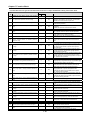
Table of Contents
◎
Overview……………………………………………………………
~ 1-4
……………………………………………………………1-1
……………………………………………………………
1.1 Characteristics……………………………………………………………………1 - 1
1.2 Purpose of Positioning Control………………………………………………1 - 3
1.3 Signal Flow of Positioning Module……………………………………………1 - 4
CHAPTER 2
Specification…………………………………………………………
~ 2-9
…………………………………………………………2-1
…………………………………………………………
2.1 General Specification…………………………………………………………… 2 - 1
2.2 Performance Specification………………………………………………………2 - 2
2.3 External Interface I/O Specification……………………………………………2 - 3
2.3.1 Input Specification…………………………………………………………………2
-3
2.3.2 Output Specification………………………………………………………………2
-4
2.3.3 External Machine and Interface Specification………………………………………2
-5
1) Pin layout of connector……………………………………………………………
2-5
2) Internal circuit of connector…………………………………………………………2
-6
2.4 The Name and Function of each Section…………………………………… 2 - 8
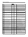
CHAPTER 3
Function……………………………………………………………
…………………………………………………………… 3-1 ~ 3-74
3.1 Positioning Control………………………………………………………………3 - 1
3.1.1 Position Control…………………………………………………………………
3 - 1
1) Control by Absolute Method (Absolute Coordinates)……………………………
3 - 1
2) Control by Incremental Method (Relative Coordinates)……………………………3
-2
3.1.2 Interpolation Control………………………………………………………………3
-3
1) 2 axis linear interpolation control…………………………………………………3
-3
2) 3 axis linear interpolation control…………………………………………………3
-6
3) 2 axis circular arcs interpolation control…………………………………………
3-8
3.1.3 Speed Control……………………………………………………………………3
- 15
3.1.4 Speed/Position Conversion Control
…………………………………………… 3 - 17
3.1.5 Position/Speed Conversion Control
…………………………………………… 3 - 18
3.2 Operating Mode………………………………………………………………… 3 - 20
3.2.1 End Operation (Single)…………………………………………………………3
- 21
3.2.2 End Operation (Repeat)…………………………………………………………3
- 23
3.2.3 Go-on Operation…………………………………………………………………3
- 25
3.2.4 Continuous Operation……………………………………………………………3
- 26
3.3 Positioning Start ………………………………………………………………3 - 27
3.3.1 General Start……………………………………………………………………3
1) Program Start
- 27
…………………………………………………………………3 - 27
2) Start by External Input Signal…………………………………………………
3 - 27
3.3.2 Simultaneous Start………………………………………………………………3
- 27
3.3.3 Synchronous Start………………………………………………………………3
- 28
1) Position Synchronous Start……………………………………………………3
- 28
2) Speed Synchronous Start……………………………………………………
3 - 28
3.3.4 Linear Interpolation Start………………………………………………………
3 - 29
1)
2 axis linear interpolation control………………………………………………
3 - 29
2)
3 axis linear interpolation control………………………………………………
3 - 29
3.3.5 Circular Arcs Interpolation Start…………………………………………………
3 - 30
1) Circular interpolation by central point……………………………………………3
- 30
2) Circular interpolation by middle point……………………………………………3
- 32
3.4 Positioning Stop……………………………………………………………… 3 - 33
3.4.1 Stop Command and Causes……………………………………………………
3.4.2 Stop Process and Priority
………………………………………………………3 - 35
3.4.3 Interpolation Stop………………………………………………………………
3.4.4 Emergency Stop
3 - 33
3 - 36
……………………………………………………………… 3 - 36
3.5 Reset after Positioning Stop………………………………………………… 3 - 37
3.6 Return to the Origin…………………………………………………………… 3 - 37
3.6.1 How to return to the origin………………………………………………………
3 - 37
3.6.2 The origin detection after approximate origin OFF…………………………………3
3.6.3 The origin detection after deceleration when approximate origin ON………………
3 - 40
3.6.4 The origin detection by the origin and High-low limit………………………………3
3.6.5 The origin detection by approximate origin
- 38
- 41
………………………………………3 - 42
3.6.6 High speed origin return…………………………………………………………3
- 43
3.7 Manual Operation……………………………………………………………… 3 - 44
3.7.1 Jog Operation……………………………………………………………………3
3.7.2 Manual Pulse Generator Operation……………………………………………
3 - 46
3.7.3 Inching Operation………]………………………………………………………3
3.7.4 Return to the position before manual operation…………]
- 44
- 48
………………………3 - 49
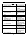
3.8 Speed Change during Positioning Operation………………………………3 - 50
3.8.1 Speed Override Command………………………………………………………3
- 50
3.8.2 Operation Step Number Change by Continuous Operation………………………3
- 51
3.8.3 Positioning Speed Override Command……………………………………………3
- 53
3.9 Position Change during Positioning Operation……………………………3 - 54
3.9.1 Position Change by Position Override……………………………………………3
- 54
3.10 Stroke High-Low Limit…………………………………………………………3 - 55
3.10.1 External Input Stroke High-Low Limit……………………………………………3
- 55
3.10.2 Software Stroke High-Low Limit…………………………………………………3
- 56
3.11 Random Position Address Value Setting on the origin and the Change of
Current Position………………………………………………………………3 - 57
3.11.1 Random Position Address Value Setting on the origin
…………………………3 - 57
3.11.2 The Change of Current Position…………………………………………………3
- 57
3.12 Floating Origin Setting………………………………………………………3 - 58
3.13 Teaching ……………………………………………………………………… 3 - 58
3.13.1 RAM Teaching and ROM Teaching……………………………………………
3 - 58
3.13.2 Single Teaching
……………………………………………………………… 3 - 59
3.13.3 Plural Teaching
……………………………………………………………… 3 - 60
3.14 Start Step Number Chang……………]………………………………………3 - 61
3.15 Skip Operation[APM_SKP] ……………………………………………………3 - 62
3.16 Starting Step Number Change during Repeating Operation…………3 - 63
3.17 M Code ………………………………………………………………………… 3 - 63
3.18 Parameter Change in Program………………………………………………3 - 65
3.18.1 Basic Parameter Setting………………………………………………………3
3.18.2 Expansion Parameter Setting…………………………………………………
3 - 66
3.18.3 Origin Return Parameter Setting………………………………………………3
3.18.4 Manual Operation Parameter Setting…………………………………………
- 65
- 67
3 - 68
3.18.5 Common Parameter Setting……………………………………………………3
- 69
3.19 Operation Data Setting………………………………………………………3 - 70
3.20 Encoder Preset…………………………………………………………………3 - 71
3.21 Error and Output Prohibition…………………………………………………3 - 72
3.22 Zone Output…………………………………………………………………… 3 - 73
3.23 Point Operation……………………………………………………………… 3 - 74
CHAPTER 4 Software Package…………………………………………………
~ 4-30
…………………………………………………4-1
…………………………………………………
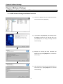
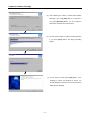
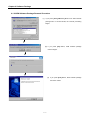
4.1 APM Software Package Installation and Removal…………………………4 - 1
4.1.1 APM Software Package Installation Processing…………………………………
4-1
4.1.2 APM Software Package Removal Processing……………………………………4
-3
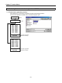
4.2 APM Software Package Basic Structure and Function List……………4 - 4
4.2.1 APM Software Package Basic Display
4.2.2 APM Software Package Function List
… ………………………………………4 - 4
……………………………………………4 - 5
4.3 Working Display…………………………………………………………………4 - 6
4.3.1 Make Working Display……………………………………………………………4
-6
4.3.2 Save Working Display……………………………………………………………4
-6
4.3.3 Structure of Working Display……………………………………………………
4-7
4.4 Offline and Online Model Setting……………………………………………4 - 8
4.4.1 Offline Model Setting
……………………………………………………………4 - 8
4.4.2 Online Model Setting……………………………………………………………
4-8
4.5 Operation Parameter and Operation Data Setting……………………… 4 - 11
4.5.1 Operation Parameter Setting……………………………………………………4
- 11
4.5.2 Operation Data Setting…………………………………………………………4
- 12
4.6 Command Command………………………………………………………… 4 - 16
4.6.1 Command Command…………………………………………………………
4 - 16
4.7 Monitoring Run…………………………………………………………………4 - 19
4.7.1 Monitoring……………………………………………………………………
4 - 19
4.8 Tracking Run …………………………………………………………………4 - 21
4.8.1 Tracking………………………………………………………………………4
- 21
4.9 Data Read/Write Function …………………………………………………4 - 24
4.9.1 Data Read/Write
……………………………………………………………4 - 24
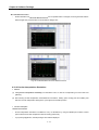
4.10 Simulation Function………………………………………………………4 - 25
4.10.1 Profile Simulation……………………………………………………………4
- 25
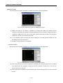
4.10.2 Circular Interpolation Simulation……………………………………………4
- 26
4.11 State Display, External I/O signal and Error History Function……4 - 28
4.11.1 State Display…………………………………………………………………4
4.11.2 External I/O Signal Function…………………………………………………
- 28
4 - 28
4.11.3 Error History Function…………………………………………………………4
- 29
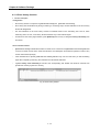
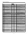
4.12 Printing Function ……………………………………………………………4 – 30
4.12.1 Print…………………………………………………………………………4
- 30
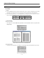
4.13 Environment Setting Function…………………………………………… 4 – 31
4.11.1 Environment Setting Function
…………………………………………………4 - 31
4.14 Others …………………………………………………………………………4 - 32
4.14.1 System Check Function………………………………………………………4
- 32
4.14.2 Error History File Writing Function……………………………………………4
- 32
CHAPTER 5
Positioning Parameter & Operation Data……………………
~ 5-26
……………………5-1
……………………
5.1 Basic Parameter ………………………………………………………………5 - 2
5.1.1 Unit
………………………………………………………………………5 - 3
5.1.2 Number of pulse per 1 rotation………………………………………………5
- 3
5.1.3 Transfer distance per 1 rotation and unit allocation……………………………5
- 3
5.1.4 Pulse Output Mode
……………………………………………………………5 - 4
5.1.5 Bias Speed……………………………………………………………………5
- 5
………………………………………………………………5 - 6
5.1.6 Speed Limit
5.1.7 Acceleration/Deceleration Time………………………………………………5
- 6
5.2 Expansion Parameter…………………………………………………
- 7
…………………………………………………………5
…………………………………………………
5.2.1 S/W High-Low Limit……………………………………………………………5
- 8
5.2.2 Backlash Compensation Amount………………………………………………5
- 8
5.2.3 Position Completion Output Time…………………………………………5
- 9
5.2.4 External Command Selection…………………………………………………
5 - 10
5.2.5 Pulse Output Direction…………………………………………………………5
5.2.6 M Code Output
……………………………………………………………… 5 - 11
5.2.7 External Command……………………………………………………………
5.2.8 External Stop
- 10
5 - 13
…………………………………………………………………5 - 13
5.2.9 External Simultaneous Start……………………………………………………5
5.2.10 External Speed/Speed switching
- 13
…………………………………………… 5 - 13
5.2.11 Equal Speed Operation S/W High-Low Limit……………………………………5
5.2.12 Position during Equal Speed Operation
- 13
………………………………………5 - 13
5.2.13 Acceleration/Deceleration Pattern……………………………………………
5 - 14
5.2.14 S-Curve Rate…………………………………………………………………5
- 14
5.3 Origin/Manual Parameter…………………………………………
5 - 15
……………………………………………………
…………………………………………
5.3.1 Origin return method……………………………………………………………5
5.3.2 The origin return direction
- 16
…………………………………………………… 5 - 16
5.3.3 The Origin Address……………………………………………………………5
- 16
5.3.4 The Origin Compensation Amount………………………………………………5
- 17
5.3.5 High Speed Origin Return………………………………………………………5
- 17
5.3.6 Low Speed Origin Return………………………………………………………5
- 17
5.3.7 Waiting Time of Resetting………………………………………………………5
- 18
5.3.8 Acceleration/Deceleration Time…………………………………………………5
- 18
5.3.9 Dwell Time……………………………………………………………………
5 - 18
5.3.10 JOG High Speed
…………………………………………………………… 5 - 18
5.3.11 JOG Low Speed
…………………………………………………………… 5 - 18
5.3.12 JOG Acceleration/Deceleration Time…………………………………………
5 - 18
5.3.13 Inching Speed………………………………………………………………
5 - 18
5.4 Common Parameter…………………………………………………
- 19
………………………………………………………………5
…………………………………………………
5.4.1 Pulse Output Level……………………………………………………………
5 - 20
5.4.2 Circular Interpolation Method…………………………………………………
5 - 21
5.4.3 Encoder Input Signal…………………………………………………………
5 - 21
5.4.4 Auto Reload……………………………………………………………………5
5.4.5 Z-shape Clear
- 21
…………………………………………………………………5 - 21
5.4.6 Zone Output……………………………………………………………………5
- 21
5.5 Operation Data ……………………………………………………………………
5 - 23
……………………………………………………
5.5.1 Step Number
5.5.2 Coordinates
…………………………………………………………………5 - 23
………………………………………………………………… 5 - 24
5.5.3 Control Method(Position/Speed)
………………………………………………5 - 25
5.5.4 Operation Pattern(End/Go on/Continue)
5.5.5 Operation Method(Single/Repeat)
………………………………………5 - 25
…………………………………………… 5 - 25
5.5.6 Goal Position…………………………………………………………………
5 - 26
5.5.7 M Code………………………………………………………………………
5 - 26
5.5.8 Acceleration/Deceleration Number………………………………………………5
- 26
5.5.9 Operation Speed………………………………………………………………5
- 26
5.5.10 Dwell Time
CHAPTER 6
………………………………………………………………… 5 - 26
Software Package Startup ……………………………………6-1
~ 6-15
……………………………………
6.1 Display Configuration for Startup………………………………………… 6 - 1
6.1.1 Command 1 Display Configuration………………………………………………6
-1
6.1.2 Command 2 and PST Display Configuration……………………………………6
- 2
6.1.3 Monitoring Display Configuration
…………………………………………… 6 - 2
6.1.4 External I/O Signal………………………………………………………………6
-3
6.1.5 State Display…………………………………………………………………6
- 3
6.1.6 Error Message
…………………………………………………………………6 - 3
6.2 Startup Mode……………………………………………………………………6 - 4
6.2.1 Command Axis Selection………………………………………………………
6-4
6.2.2 Execute…………………………………………………………………………6
6.2.3 Startup by Software Package
-4
……………………………………………………6 - 4
6.2.4 Jog Operation by Software Package……………………………………………
6-5
6.2.5 Teaching Operation by Software Package………………………………………
6-5
6.2.6 Point Operation by Software Package
………………………………………… 6 - 6
6.3 Command Icon………………………………………………………………… 6 - 7
6.4 Software Package Startup Examples………………………………………6 - 8
6.4.1 Origin Return
………………………………………………………………… 6 - 8
6.4.2 Indirect Setting…………………………………………………………………
6-9
6.4.3 External Simultaneous Start……………………………………………………6
- 11
6.4.4 Circular Arcs Interpolation………………………………………………………6
- 12
6.4.5 Speed Synchronization………………………………………………………
6 - 13
6.4.6 Teaching(Array)………………………………………………………………
6 - 14
6.4.7 Point Operation…………………………………………………………………6
CHAPTER 7
7.1
- 15
Function Block…………………………………………………
~ 7-34
…………………………………………………7-1
…………………………………………………
Function Block Registration for Positioning Module in GMWIN…… 7 - 2
7.1.1 Registration Procedure of Function Block…………………………………………7
-2
7.1.2 Common Items of Function Block…………………………………………………7
-2
7.2 Function Block for Module Information Reading…………………………7 - 3
7.2.1 Current Operation State Code Information Read…………………………………
7-3
7.2.2 Current Operation State Bit Information Read……………………………………
7-3
7.3 Function Block for Parameter Setting………………………………………7 - 4
7.3.1 Basic Parameter Setting…………………………………………………………7
-4
7.3.2 Expansion Parameter Setting……………………………………………………7
-5
7.3.3 Common Parameter Setting
……………………………………………………7 - 6
7.3.4 Origin Return Parameter Setting…………………………………………………7
7.3.5 Manual Operation Parameter Setting……………………………………………
-7
7-8
7.4 Function Block for Operation Data Setting………………………………7 - 9
7.4.1 Operation Data Setting…………………………………………………………
7-9
7.5 Function Block for Automatic Operation…………………………………7 - 10
7.5.1 Origin Return Start……………………………………………………………7
- 10
7.5.2 Direct Start……………………………………………………………………7
- 10
7.5.3 Indirect Start……………………………………………………………………7
- 11
7.5.4 Linear Interpolation Start………………………………………………………7
- 11
7.5.5 Circular Arcs Interpolation Start…………………………………………………7
- 12
7.5.6 Simultaneous Start……………………………………………………………7
– 12
7.5.7 PTP Start………………………………………………………………………7
- 24
7.6 Function Block for Manual Operation……………………………………7 - 13
7.6.1 Jog Operation…………………………………………………………………
7 - 13
7.6.2 Inching Operation………………………………………………………………7
7.6.3 Manual Pulse Operation………………………………………………………
- 13
7 - 14
7.6.4 Return to the position before manual operation…………………………………7
- 14
7.7 Function Block for Auxiliary Operation……………………………………7 - 15
7.7.1 Position Synchronization………………………………………………………
7 - 15
7.7.2 Speed Synchronization…………………………………………………………7
- 15
7.7.3 Position Override………………………………………………………………7
- 16
7.7.4 Speed Override
………………………………………………………………7 - 16
7.7.5 Position/Speed Override
…………………………………………………… 7 - 17
7.7.6 Position/Speed switching Control………………………………………………7
7.7.7 Speed/Position switching Control
- 17
…………………………………………… 7 - 17
7.7.8 Skip Operation…………………………………………………………………7
- 18
7.7.9 Continuous Operation…………………………………………………………
7 - 18
7.7.10 Setting Step Number Designation……………………………………………
7 - 18
7.7.11 Start Step Number Designation in case of Repeat Operation…………………7
7.7.12 Stop…………………………………………………………………………
- 19
7 - 19
7.8 Function Block for Teaching……………………………………………… 7 - 20
7.8.1 Position/Speed Teaching Function Block - Single………………………………
7 - 20
7.8.2 Position/Speed Teaching Function Block - Plural………………………………
7 - 20
7.9 Function Block for Error……………………………………………………7 - 21
7.9.1 Emergency Stop………………………………………………………………
7 - 21
7.9.2 Error Reset/Release of Output Prohibition………………………………………7
- 21
7.10 Other Function Block………………………………………………………7 - 22
7.10.1 Zone Output Permitted………………………………………………………
7.10.2 M Code OFF
7 - 22
…………………………………………………………………7 - 22
7.10.3 Preset………………………………………………………………………
7 - 23
7.10.4 Floating Origin………………………………………………………………
7 - 23
7.10.5 Encoder Preset………………………………………………………………7
- 23
7.10.6 Encoder Value Read…………………………………………………………7
- 24
7.11 Error Code on Function Block …………………………………………7 - 24
CHAPTER 8
Internal Memory and I/O Signal……………………………
………………………………
………………………………8-1 ~ 8-17
8.1 Internal Memory………………………………………………………………8 - 1
8.1.1 Basic Parameter………………………………………………………………8
- 1
8.1.2 Expansion Parameter…………………………………………………………8
- 2
8.1.3 Manual Operation Parameter…………………………………………………8
- 3
8.1.4 Origin Return Parameter……………………………………………………8
- 3
8.1.5 Common Parameter……………………………………………………………8
- 4
8.1.6 Operation Data…………………………………………………………………8
- 5
8.1.7 Command Information…………………………………………………………8
- 7
8.1.8 State Information………………………………………………………………8
- 9
8.2 I/O Signal ………………………………………………………………………8 - 13
8.2.1 Contents of I/O Signal…………………………………………………………8
8.2.2 Use of I/O Signal
CHAPTER 9
- 13
…………………………………………………………… 8 - 14
Command ……………………………………………………… 9-1 ~ 9-18
9.1 Contents of Command Code……………………………………………9 - 1
9.2 Use of Command Code……………………………………………………9 - 2
9.2.1 Origin Return Start……………………………………………………………9
- 2
9.2.2 Floating Origin Setting………………………………………………………9
- 2
9.2.3 Direct Start…………………………………………………………………
9 - 3
9.2.4 Indirect Start………………………………………………………………
9 - 3
9.2.5 Linear Interpolation Start
…………………………………………………9 - 4
9.2.6 Circular Arcs Interpolation Start………………………………………………9
- 4
9.2.7 Simultaneous Start……………………………………………………………9
- 5
9.2.8 Speed/Position switching
……………………………………………………9 - 5
9.2.9 Position/Speed switching
……………………………………………………9 - 5
9.2.10 Stop…………………………………………………………………………9
- 6
9.2.11 Skip Operation………………………………………………………………9
- 6
9.2.12 Position Synchronization………………………………………………………9
- 6
9.2.13 Speed Synchronization………………………………………………………9
- 7
9.2.14 Position Override……………………………………………………………9
- 8
………………………………………………………………9 - 8
9.2.15 Speed Override
9.2.16 Positioning Speed Override……………………………………………………9
- 9
9.2.17 Continuous Operation…………………………………………………………9
- 9
9.2.18 Inching Start…………………………………………………………………9
- 9
9.2.19 Automatic Operation Point Return Function……………………………………9
- 10
9.2.20 Start Step Number Change……………………………………………………9
- 10
9.2.21 Repeat Step Number Change…………………………………………………9
- 10
9.2.22 M code release………………………………………………………………9
- 11
9.2.23 Current Position Preset………………………………………………………9
- 11
9.2.24 Zone Output Permitted………………………………………………………9
- 11
9.2.25 Zone Output Prohibited
…………………………………………………… 9 - 12
…………………………………………………………… 9 - 12
9.2.26 Encoder Preset
9.2.27 Single Teaching………………………………………………………………9
9.2.28 Array Teaching………………………………………………………………
- 12
9 - 13
9.2.29 Basic Parameter Setting………………………………………………………9
- 14
9.2.30 Expansion Parameter Setting…………………………………………………9
- 14
9.2.31 Origin Return Parameter Setting………………………………………………9
- 15
9.2.32 Manual Operation Parameter Setting…………………………………………
9 - 15
9.2.33 Common Parameter Setting…………………………………………………
9 - 16
9.2.34 Operation Data Setting………………………………………………………
9 - 16
9.2.35 Emergency Stop
…………………………………………………………… 9 - 17
9.2.36 Error Reset, Release of Output Prohibition……………………………………
9 - 17
9.2.37 Error History Reset……………………………………………………………9
9.2.38 Point Operation
CHAPTER 10
- 17
………………………………………………………………9 - 18
GM Program………………………………………………
……………………………………………… 10-1 ~ 10-12
10.1 Before Program………………………………………………………………10 - 1
10.2 Basic Program……………………………………………………………… 10 - 2
10.3 Application Program…………………………………………………………10 - 3
10.3.1 End Operation, Go-on Operation, Continuous Operation Positioning……………10
-3
10.3.2 Positioning by M Code………………………………………………………10
- 5
10.3.3 2 axis linear interpolation………………………………………………………10
-7
10.3.4 Position Teaching by MMI……………………………………………………
10.3.5 Position Teaching by Jog Operation and Inching Operation
10 - 9
…………………10 - 10
10.3.6 Positioning Speed Change, Next Move………………………………………10
CHAPTER 11
- 11
MK Program………………………………………………
……………………………………………… 11-1 ~ 11-50
11.1 Before using the Program ………………………………………………11 - 1
11.2 Basic Program ……………………………………………………………11 - 2
11.2.1 Basic(Floating Origin Setting)…………………………………………………11
-2
11.2.2 Basic(Linear Interpolation Start-Floating Origin Setting)………………………11
- 3
11.2.3 Basic(Circular Arcs Interpolation Start-Floating Origin Setting)…………………11
-5
11.2.4 Deceleration Stop(Origin Return)………………………………………………11
-7
11.2.5 Single Operation(Operation Step Number Designation)…………………………11
-8
11.2.6 Single Operation(by External Input Signal)……………………………………
11 - 9
11.2.7 Equal Speed Operation(Operation Step Number Designation)…………………11
- 10
11.2.8 Simultaneous Start…………………………………………………………
11 - 11
11.2.9 Position Synchronous Start…………………………………………………
11 - 12
11.2.10 Speed Synchronous Start…………………………………………………
11 - 13
…………………………………………………………11 -15
11.2.11Emergency Stop
11.2.12Jog Operation
…………………………………………………………… 11 - 16
11.2.13 Manual Pulse Generator (or Encoder Operation)……………………………11
11.2.14 Inching Operation
…………………………………………………………11 - 18
11.2.15 Move to the Position before Manual Operation………………………………11
- 19
………………………………………………………… 11 - 20
11.2.16 Speed Override
11.2.17 Position Override…………………………………………………………
11 - 21
11.2.18 Positioning Speed Override…………………………………………………11
11.2.19 Operation Step Number Change by Continuous Operation…………………
11.2.20 Skip Operation
- 17
- 22
11 - 23
……………………………………………………………11 - 24
11.2.21 Operation Step Change in Repeat Operation………………………………11
- 25
11.2.22 Current Position Change……………………………………………………11
- 26
11.2.23 Speed Teaching
………………………………………………………… 11 - 27
11.2.24 Position Teaching…………………………………………………………
11 - 28
11.2.25 Parameter Change…………………………………………………………11
11.2.26 M Code Mode
11.2.27 Zone Setting
- 29
……………………………………………………………11 - 31
………………………………………………………………11 - 32
11.2.28 Operation Data Setting……………………………………………………
11 - 33
11.2.29 Point Operation(Origin Return)……………………………………………
11 - 34
11.3 Application Program………………………………………………………11 - 36
11.3.1 Position/Speed Teaching by MMI
………………………………………… 11 - 36
11.3.2 End Operation, Go-on Operation, Continuous Operation Positioning…………
11.3.3 Positioning by M Code
11 - 39
……………………………………………………11 - 41
11.3.4 2 axis linear interpolation operation…………………………………………
11 - 43
11.3.5 Position Teaching by Jog Operation and Inching Operation……………………11
11.3.6 Speed Change, Next Move
- 45
… …………………………………………… 11 - 48
CHAPTER 12 Operation Order and Installation……………………………
~ 12-8
……………………………12-1
……………………………
12.1 Operation Order………………………………………………………………12 - 1
12.2 Installation……………………………………………………………………12 - 2
12.2.1 Installation Environment………………………………………………………12
12.2.2 Cautions in Handling
-2
…………………………………………………………12 - 2
12.3 Wiring………………………………………………………………………… 12 - 2
12.3.1 Cautions in Wiring……………………………………………………………12
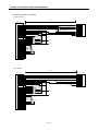
12.3.2 Connection with Servo and Stepping Motor Driver……………………………
1) Connection with MR-H❚A(Line Drive)
-2
12 - 3
…………………………………………12 - 3
2) Connection with MR-J2/J2S-❚A(Line Drive)……………………………………
12 - 4
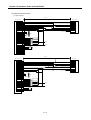
3) Connection with MR-J❚A(Line Drive)……………………………………………12
-5
4) Connection with MR-C❚A(Line Drive)……………………………………………12
-6
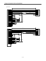
5) Connection with MINAS A series (Line Drive)……………………………………12
-7
6) Connection with PYO series (Line Drive)………………………………………
12 - 7
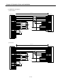
7) Connection with CACR(R series)(Line Drive)……………………………………12
8) Connection with VEXTA UDX2107……………………………………………
-8
12 - 9
9) Connection with VEXTA UPD…………………………………………………12
- 10
10) Connection with VEXTA-FX…………………………………………………12
- 11
11) Connection with FDA-3000 AC Servo Driver(Open Collector)…………………12
- 12
12) Connection with FDA-5000 AC Servo Driver (Open Collector)…………………12
- 12
13) Connection with FDA-5000 AC Servo Driver (Open Collector)…………………12
14) SGDA-□□□P Connection Example
- 13
………………………………………12 - 14
APPENDIX 1
Positioning Terminology…………………………
~ APP.1-12
…………………………APP.1-1
…………………………
APPENDIX 2
Operation Data Internal Memory Address……
~ APP.2-12
……APP.2-1
……
1) Internal Memory Address of X axis Operation Data…………………………APP.2
-1
2) Internal Memory Address of Y axis Operation Data…………………………APP.2
-5
3) Internal Memory Address of Z axis Operation Data…………………………APP.2
-9
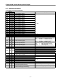
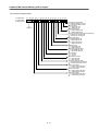
Chapter 1 Overview
Chapter 1
Overview
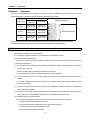
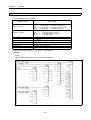
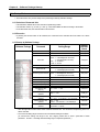
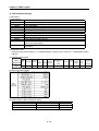
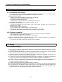
This user’s manual describes the standard of positioning module, installation method, the method to use each
positioning function, programming and the wiring with external machine as below.
No. of
Control Axis
Product Name
Related S/W Package
Open
Collector
Line Drive
1 Axis
G4F-PP1O
G6F-PP1O
G4F-PP1D
G6F-PP1D
2 Axis
G4F-PP2O
G6F-PP2O
G4F-PP2D
G6F-PP2D
3 Axis
G4F-PP3O
G6F-PP3O
G4F-PP3D
G6F-PP3D
APM S/W Package
G4F-PP1O,G4F-PP2O,G4F-PP3O,G4F-PP1D,G4F-PP2D,G4F-PP3D,G6F-PP1O,G6F-PP2O,G6F-PP3O,
G6F-PP1D,G6F-PP2D,G6F-PP3D modules are described APM(advanced position module).
1.1 Characteristics
The features of positioning module is as follows :
1) The positioning module is available for GLOFA GM Series and MASTER-K Series.
2) Various positioning control function
It has various functions needed for positioning system such as positioning control at the random position,
equal speed operation etc.
(1) The operation data including positioning address and operation method, operation pattern is available to
set max. 400 at each axis.
With this operation data, the positioning at each axis is carried out.
(2/3 axis interpolation control and 2/3 axis simultaneous setting is available.)
(2) In case of positioning at each axis, the straight line control (3 axis simultaneous setting available) is
available.
This control enables the single position control by one operation data and the continuous position control
by plural operation data.
(3) In case of positioning more than 2 axis, speed control, interpolation control and circular arcs interpolation
control of 2 axis are available.
(4) According to the control method designated by each operation data and parameter, there are position
control, speed control, speed/position switching control, position/speed switching control.
(5) Abundant origin return control function.
(A) The method of origin return is shown as below and available to select one from 5 methods.
▶The origin detection after approximate origin OFF
▶The origin detection after deceleration in case of approximate origin ON
▶The origin detection by the origin and high-low limit
▶The origin detection by approximate origin
1-1
Chapter 1 Overview
▶High speed origin detection
(B) Available to execute the positioning control (floating origin setting) from random position to the origin of
machine.
(6) The Acceleration/Deceleration method contains trapezoid and S-type to select.
3) High speeding of setting process
Due to the realization of high speeding of positioning operation setting process, the setting process time
reduced by 4ms~ 5ms.
Therefore, the delay time will not occur between axis in case of simultaneous setting (using several axis or
during interpolation operation).
4) High speeding of pulse output and making a long-distance connection with driver
In case of using Line Drive type (G4F-PP1D, G4F-PP2D, G4F-PP3D, G6F-PP1D, G6F-PP2D, G6F-PP3D), it
is available to realize the high speeding and making a long-distance connection.
5) Simplicity of maintenance
Various data such as positioning data, parameter etc. is saved in flash memory within positioning module.
6) The number of positioning module using in one base is not limited.
(but available to use within the range that satisfies the capacity of power module)
7) Self-diagnosis, monitoring, test by strong positioning software package is available.
(1) Diagnosis for I/O signal line
(2) Monitoring
(3) Tracking
(4) Simulation
(5) Detailed information and solution for each error is provided.
(6) Printer function in various ways is provided.
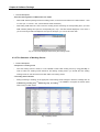
(7) Operation data editing of each axis is available in Excel program.
1-2
Chapter 1 Overview
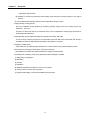
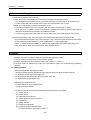
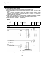
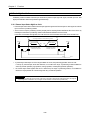
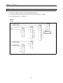
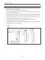
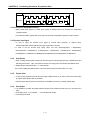
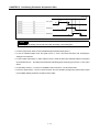
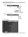
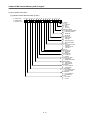
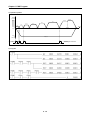
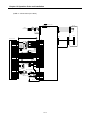
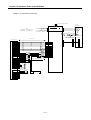
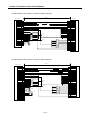
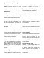
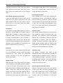
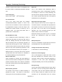
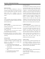
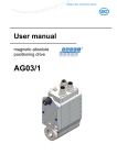
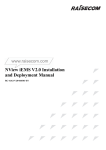
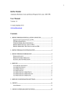
1.2 Purpose of Positioning Control
The purpose of positioning module is to transfer the moving objects (unprocessed items, tools etc.) by setting
speed from the current position and stop them on the setting position correctly. And it also control the position of
high precision by positioning pulse string signal as it is connected to various servo running devices or stepping
motor control running devices.
In application, it can be used widely with engineering machine, semiconductor assembly machine, grinder, small
machine center, lifter etc.
CPU Module
Positioning Module
Driver
Stepping Motor
Normal Rotation
Pulse
Program
Setting
Data
Read,
Write
Polyphase
Pulse
Generator
Pulse
AMP
M
Reverse Rotation
Pulse
APM
Software
Package
[Fig. 1-1] Overview of Position Control for Stepping Motor
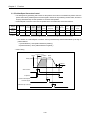
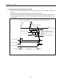
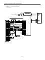
CPU Module
Positioning Module
Driver
SERVO Motor
Normal Rotation
Pulse
Setting
Data
Program
Read,
Deviation
D/A
Counter
Converter
Speed SERVO
Order
M
AMP
Reverse Rotation
Pulse
Write
Interface
PG
Feedback Pulse
Speed
APM
Software
Package
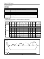
Accumulative Pulse
SERVO Motor Speed
Pulse Amount
Time
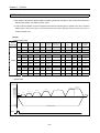
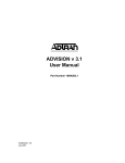
[Fig. 1-2] Overview of Position Control for SERVO Motor
1-3
Chapter 1 Overview
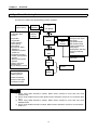
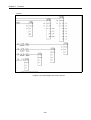
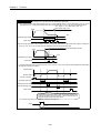
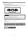
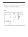
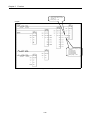
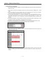
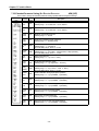
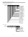
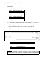
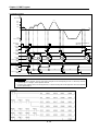
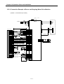
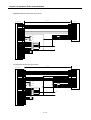
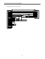
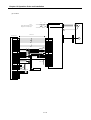
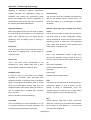
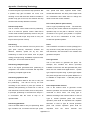
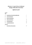
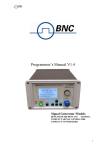
1.3 Signal Flow of Positioning Module
The flow of PLC system using the positioning module is as follows :
.
Program Writing
Setting of Parameter
and Operation Data
for Control
GMWIN
KGLWIN
PLC
CPU Module
APM
Software
Package
Positioning
Test operation
- Jog operation
- Inching operation
- Indirect setting
- Direct setting
- Synchronous setting
- Straight line
interpolation operation
- Circular arcs
interpolation operation
- Position synchronization
operation
- Speed synchronization
operation
Monitoring and test of
positioning action,
using the setting command
Motor Driving by pulse
string received from
positioning module
Module
SERVO
AMP
External Signal
MPG
Encoder
External setting signal
Emergency stop signal
Stop signal
Jog operation signal
Skip operation signal
External simultaneous
setting signal
Speed/position switching
signal–To positioning
module
Setting by external
pulse string
Motor
Action by SERVO
indication
Working
Transfer Drive Ready
signal and Home signal
to positioning module
Point
1) When using GM4 CPUA,B,C module, ROM version should be more than V2.6 and
GMWIN V3.6.
2) When using K300S CPUA module, ROM version should be more than V3.1 and KGL-WIN
V3.3.
3) When using GM6 CPUA,B,C module, ROM version should be more than V2.0 and
GMWIN V3.63
4) When using K200S CPUA,B,C module, ROM version should be more than V2.3 and KGLWIN V3.3.
1-4
CHAPTER 2 Specification
CHAPTER 2
Specification
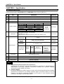
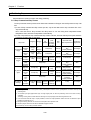
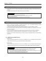
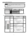
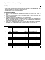
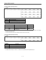
2.1 General Specification
The General Specification for GLOFA GM series and MASTER-K series is shown on [Table 2-1].
No.
Items
Specification
Reference
1
Use Temperature
0 ~ 55 °C
2
Storage Temp.
−25 ~ +70 °C
3
Use humidity
5 ~ 95%RH, no dew
4
Storage humidity
5 ~ 95%RH, no dew
In case of Intermittent vibration
5
Vibration-resistant
10
57
10
57
Frequency
Acceleration
≤ f < 57Hz
−
2
9.8m/s {1G}
≤ f ≤ 150Hz
In case of Continuous vibration
Frequency
Acceleration
≤ f < 57Hz
−
2
4.9m/s {0.5G}
≤ f ≤ 150Hz
Amplitude
0.075mm
−
Amplitude
0.035mm
−
Times
X, Y, Z
10 times
each direction
• Max. impact acceleration : 147 m/s {15G}
• Application time : 11ms
• pulse wave type : semi-sine wave pulse (3 times each direction X,Y,Z)
IEC61131-2
2
6
Impact-proof
± 1,500 V
LG산전내부
시험규격기준
Voltage : 4kV (Touch discharge)
IEC61131-2
IEC1000-4-2
27 ~ 500 MHz, 10 V/m
IEC1131-2,
IEC1000-4-3
Square wave
impulse noise
Electrostatic
discharge
Radiant
electromagnetic
field noise
7
IEC61131-2
Noise-resistant
Digital I/O
Fast transient
/ Bust noise
Classification
Power
modul
e
Digital I/O
(more than 24V)
Voltage
2kV
1kV
8
Surrounding
environment
No corrosive gas, no dust
9
Use altitude
Less than 2,000m
10
Pollution
Less than 2
11
Cooling method
(less than 24V)
Analog I/O
Communication
interface
0.25kV
IEC1131-2
IEC1000-4-4
Natural air-conditioning
Table 2.1 General Specification
Point
1
2
3
1) IEC(International Electrotechnical Commission)
: International civil community that promotes international cooperation for standardization of
electric/electro technology, publishes international standard and operates suitability
assessment system related to the above.
2) Pollution Degree
: An index to indicate the pollution degree of used environment that determines the insulation
performance of the device. For example, pollution degree 2 means the state to occur the
pollution of non-electric conductivity generally, but the state to occur temporary electric
conduction according to the formation of dew.
2-1
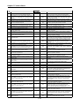
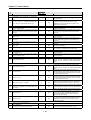
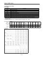
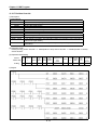
CHAPTER 2 Specification
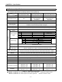
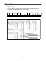
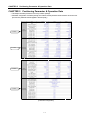
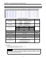
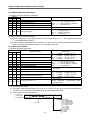
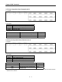
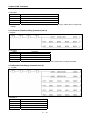
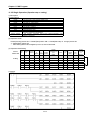
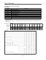
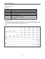
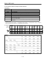
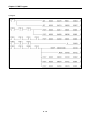
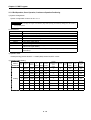
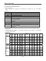
2.2 Performance Specification
The Performance Specification for positioning module is shown on [Table 2-2].
G4F-PP2O,G4F-PP2D
Model G4F-PP1O,G4F-PP1D
G6F-PP1O,G6F-PP1D
G6F-PP2O,G6F-PP2D
Items
G4F-PP3O,G4F-PP3D
G6F-PP3O,G6F-PP3D
No. of control axis
1 axis
2 axis
3 axis
Interpolation function
N/A
2 axis linear interpolation
2 axis circular arcs
interpolation
2/3 axis linear interpolation
2 axis circular arcs
interpolation
Control method
Position control, Speed control, Speed/Position control, Position/Speed control
Control unit
Pulse, ㎜, inch, degree
Positioning data
Each axis has 400 data range.(Operation step number 1 ~ 400)
Available to set with software package or program
Software package
Available (connected with RS-232C Port of CPU module)
Back-up
Save the parameter, operation data in Flash ROM (No Battery)
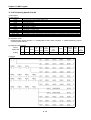
Positioning
method
POSITIONING
Position address
range
Absolute method/Relative method
㎜
Inch
degree
pulse
Absolute method
Relative method
-214748364.8~ 214748364.7(㎛)
-21474.83648 ~ 21474.83647
-21474.83648 ~ 21474.83647
-2147483648 ~ 2147483647
-214748364.8~ 214748364.7(㎛)
-21474.83648 ~ 21474.83647
-21474.83648 ~ 21474.83647
-2147483648 ~ 2147483647
Open collecor
Speed range
㎜
Inch
degree
pulse
-214748364.8~ 214748364.7(㎛)
-21474.83648 ~ 21474.83647
-21474.83648 ~ 21474.83647
-2147483648 ~ 2147483647
Line driver
0.01 ~ 20000000.00(㎜/min)
0.001 ~ 2000000.000(Inch/min)
0.001 ~ 2000000.000(degree/min)
1 ~ 200,000(pulse/sec)
1 ~ 1,000,000(pulse/sec)
Acceleration/decel
-eration process
Acceleration/decel
-eration time
Speed/Position, Position/Speed
Switching control
Trapezoid type, S-type
1 ~ 65535 ㎳
Selection available from 4 types of acceleration/deceleration pattern
Max. output pulse
G4F-PP1O, G4F-PP2O, G4F-PP3O, G6F-PP1O, G6F-PP2O, G6F-PP3O : 200kpps
G4F-PP1D, G4F-PP2D, G4F-PP3D, G6F-PP1D, G6F-PP2D, G6F-PP3D : 1 Mpps
Max. connection
distance
G4F-PP1O, G4F-PP2O, G4F-PP3O, G6F-PP1O, G6F-PP2O, G6F-PP3O : 2m
G4F-PP1D, G4F-PP2D, G4F-PP3D, G6F-PP1D, G6F-PP2D, G6F-PP3D : 10m
Error indication
Indicated by 17 segment indicator and LED(only G6F-PP O, G6F-PP D is indicated by LED)
Max. Encoder input
200kpps
I/O indication
Indicated by 17 segment indicator and LED(G4F-PP O, G4F-PP D)
Connection connector
40 Pin connector
Size of use cable
AWG #24
I/O share point
32 points
Consumable current(㎃)
G4F-PP1O : 730
G4F-PP1D : 700
G6F-PP1O : 480
G6F-PP1D : 630
G4F-PP2O : 760
G4F-PP2D : 720
G6F-PP2O : 490
G6F-PP2D : 750
G4F-PP3O : 770
G4F-PP3D : 740
G6F-PP3O : 500
G6F-PP3D : 840
Weight(g)
G4F-PP1 : 310
G6F-PP1 : 125
G4F-PP2 : 325
G6F-PP2 : 145
G4F-PP3 : 330
G6F-PP3 : 151
Table 2.2 Performance Specification
※ G4F-PP O, G6F-PP O : Pulse output is Open Collector type and
shows the number of axis.
G4F-PP D, G6F-PP D : Pulse output is Line Driver type and
shows the number of axis.
2-2
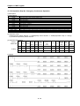
CHAPTER 2 Specification
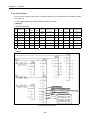
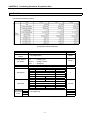
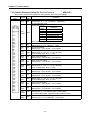
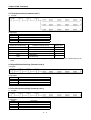
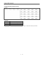
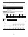
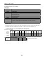
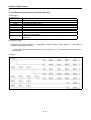
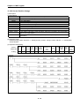
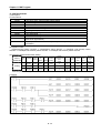
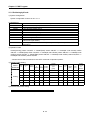
2.3 External Interface I/O Specification
Here describes the I/O interface with external equipment.
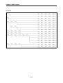
2.3.1 Input Specification
Signal name
Rated input
voltage/curret
Use voltage
range
On
voltage/current
Off
voltage/current
Input
resistance
Response
time
Approximate
origin
DC 24V/4.7㎃
DC 20.4~26.4V
≥DC 16V/3.1㎃
≤DC 4V/1.0㎃
Approx. 5.1㏀
≤0.1㎳
External highlimit
DC 24V/4.7㎃
DC 20.4~26.4V
≥DC 16V/3.1㎃
≤DC 4V/1.0㎃
Approx. 5.1㏀
≤0.1㎳
External low-limit
DC 24V/4.7㎃
DC 20.4~26.4V
≥DC 16V/3.1㎃
≤DC 4V/1.0㎃
Approx. 5.1㏀
≤0.1㎳
Emergency stop
DC 24V/4.7㎃
DC 20.4~26.4V
≥DC 16V/3.1㎃
≤DC 4V/1.0㎃
Approx. 5.1㏀
≤0.5㎳
External stop
DC 24V/4.7㎃
DC 20.4~26.4V
≥DC 16V/3.1㎃
≤DC 4V/1.0㎃
Approx. 5.1㏀
≤0.1㎳
External
command
DC 24V/4.7㎃
DC 20.4~26.4V
≥DC 16V/3.1㎃
≤DC 4V/1.0㎃
Approx. 5.1㏀
≤0.1㎳
Jog reverse
operation
DC 24V/4.7㎃
DC 20.4~26.4V
≥DC 16V/3.1㎃
≤DC 4V/1.0㎃
Approx. 5.1㏀
≤0.1㎳
Drive Ready
DC 24V/4.7㎃
DC 20.4~26.4V
≥DC 16V/3.1㎃
≤DC 4V/1.0㎃
Approx. 5.1㏀
≤0.1㎳
External
simultaneous
start
DC 24V/4.7㎃
DC 20.4~26.4V
≥DC 16V/3.1㎃
≤DC 4V/1.0㎃
Approx. 5.1㏀
≤0.5㎳
DC 24V/8.9㎃
DC 20.4~26.4V
≥DC 16V/6.0㎃
≤DC 4V/1.6㎃
Approx. 2.7㏀
On: ≤0.4㎳
DC 5V/8.9㎃
DC 4.25~5.5 V
≥DC 2.5V/6.0㎃
≤DC 1V/1.9㎃
Approx. 570Ω
On: ≤0.4㎳
≤DC 1V/1.0㎃
Approx. 940Ω
≤0.6㎳
≤3㎲
Origin
≤3㎲
1≥㎳
DC 5V/7.0㎃
DC 4.25~5.5 V
≥DC 2.5V/3.0㎃
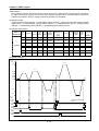
Encoder input : based on RS-422A Line Driver Level (Am26LS31)
1) Pulse width
Manual pulse
generator
/ Encoder input
≥5㎲
≥2.5㎲
≥2.5㎲
Duty rate 50%
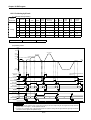
2) Phase difference
If A phase input pulse precedes B phase input pulse, the
position address value increases.
≥1.25㎲
Speed/Position
switching signal
DC 24V/4.7㎃
DC 20.4~26.4V
If B phase input pulse precedes A phase input pulse, the
position address value decreases.
≥DC 16V/3.1㎃
2-3
≤DC 4V/1.0㎃
Approx.5.1㏀
≤O.1㎳
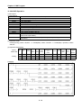
CHAPTER 2 Specification
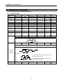
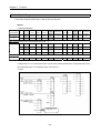
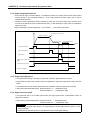
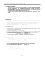
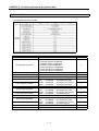
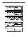
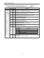
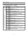
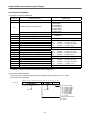
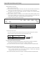
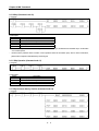
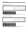
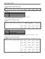
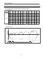
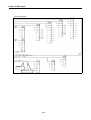
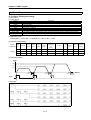
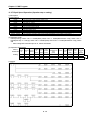
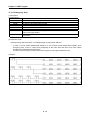
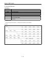
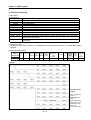
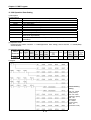
2.3.2
Output Specification
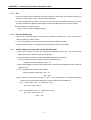
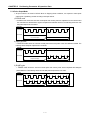
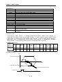
1) Pulse Output Specification
Signal Name
Pulse Output
(CW/Pulse/A
phase)
Rated load
voltage
Use load
voltage range
Max. load current
/ Inrush current
Max. voltage
falling (ON)
Leakage
current (OFF)
Response
Time
DC 5~24V
DC 4.75~26.4V
50㎃(1 point)
/ ≤200㎃ 10㎳
≤DC 0.5V
≤0.1㎃
-
▷Differential Line Drive based on Am26C31(only Line Drive pulse output type)
▷CW/CCW type, Pulse/Sign type, A phase/B phase type can be selected from pulse output mode of basic
parameter for program and S/W Package.
▷The relation of Pulse output mode (setting from basic parameter of PLC program or S/W Package),
Pulse output direction (setting from expansion parameter of PLC program or S/W Package) and
Pulse output level (setting from common parameter of PLC program or S/W Package) is as follows.
Selection of output signal level
pulse
output
Forward direction
Reverse direction
mode
Forward
Reverse
Forward
Reverse
Pulse Sign
(CCW/Sign/B
phase)
CW
CCW
Pulse
Sign
High
Low
High
A phase
B phase
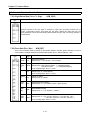
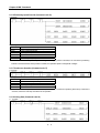
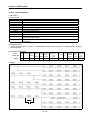
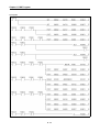
2) Transistor Output Specification_Sink type(Zone output)
Items
Specification
Isolation method
Rated load voltage
Voltage range of use load
Max. load current
Leakage current when OFF
Max. Inrush current
Max. voltage falling when ON
Response
Off → On
time
On → Off
Common method
Action indication
Photo Coupler Isolation
DC 24V
DC 20.4 ~ 26.4V
100 ㎃
Less than 0.1 mA
Less than 0.4 A / 10 ms
DC 1.0 V
Less than 2 ms
Less than 2 ms
3points / 1 COM
LED indication
※ Not available for G6F-PP O, G6F-PP D.
2-4
Low
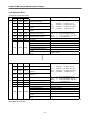
CHAPTER 2 Specification
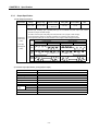
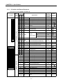
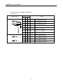
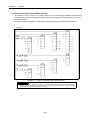
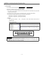
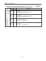
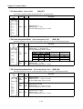
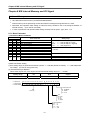
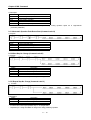
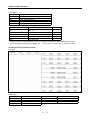
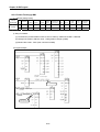
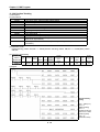
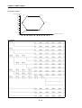
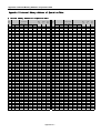
2.3.3
I/O Interface with External Equipment
1) Pin layout of connector(G4F-PP O, G4F-PP D)
Pin layout
1
2
3
4
5
6
7
8
Class Pin no.
ificati X
Y
Z
on axis axis axis
Signal Name
21
22
23
24
41
42
43
44
61
62
63
64
FP+
FPRP+
RP-
25
45
65 OV+
※1
9 10
11 12
Pulse output (differential +)
Pulse output (differential -)
Pulse sign (differential +)
Pulse sign (differential -)
※1
Signal
Action
direction
positioning condition
-external
Æ
Æ
Æ
Æ
High limit
Å
Low limit
Å
26
46
66 OV-
27
47
67 STOP
External stop signal
Å
28
48
68 DOG
Approximate origin
Å
29
49
69 VTP
Speed/Position switching signal
Å
70 ECMD
External
command signal
13 14
15 16
17 18
19 20
21 22
25 26
27 28
29 30
31 32
33 34
35 36
37 38
39 40
FUNCTION per AXIS
23 24
41 42
1
2
43 44
3
4
45 46
5
6
47 48
7
8
49 50
9 10
51 52
11 12
53 54
13 14
55 56
15 16
57 58
17 18
59 60
19 20
61 62
21 22
63 64
23 24
65 66
25 26
67 68
27 28
69 70
29 30
71 72
31 32
73 74
33 34
75 76
35 36
77 78
37 38
79 80
39 40
2/3 axis
COMMON FUNCTION
1 axis
30
50
Start
Å
Skip
Å
JOG+(Forward)
Å
31
51
71 JOG-
JOG reverse opration
Å
32
52
72 COM
Common
(OV+,OV-STOP,DOG,VTP,ECMD,JOG-)
Ù
33
53
73 DRVIN
Drive Unit Ready signal
Å
34
54
74 DRVIN COM Drive Unit Ready signal Common
Ù
35
55
75 HOME +24V Zero signal (+24V)
Å
36
56
76 NC
No use
37
57
77 HOME +5V
Zero signal (+5V)
38
39
40
58
59
60
78 HOME COM Zero signal(+24V, +5V) Common
79 NC
No use
80 NC
No use
※1
Å
Ù
1
MPG A+
Manual pulse generator/Encoder A+ input
Å
2
MPG A-
Manual pulse generator/Encoder A- input
Å
3
MPG B+
Manual pulse generator/Encoder B+ input
4
5
6
MPG BMPG Z+
MPG Z-
Manual pulse generator/Encoder B- input
Encoder Z+ input
Encoder Z- input
Å
Å
Å
Å
7
CON
External simultaneous start
Å
※1
8
EMG
Emergency stop
Å
9
10
11
12
13
14
15,16,17,
18,19,20
NC
COM
Out 1
Out 2
Out 3
COM
No use
(CON, EMG)Common
Transistor output of Zone 1
Transistor output of Zone 2
Transistor output of Zone 3
ZONE Common
Ù
Æ
Æ
Æ
Ù
NC
No use
※1 : High/low limit, drive Unit Ready signal, emergency stop signal should be connected to DC24V.
2-5
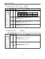
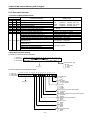
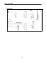
CHAPTER 2 Specification
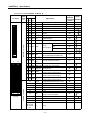
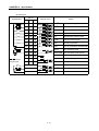
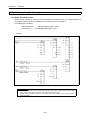
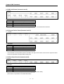
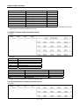
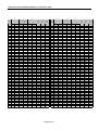
2) Pin layout of connector(G6F-PP O, G6F-PP D)
Pin layout
1
2
3
4
5
6
7
8
9
10
Pin no.
Class
ificati X
Y
Z
on axis axis axis
Signal Name
21A
1B
21B
22A
2B
22B
23A
3B
24A
4B
FP+
FP23B RP+
24B RP-
25A
5B
25B
Pulse output (differential +)
Pulse output (differential -)
Pulse sign (differential +)
Pulse sign (differential -)
※1
OV+
※1
Signal
Action
direction
positioning condition
-external
Æ
Æ
Æ
Æ
High limit
Å
Low limit
Å
26A
6B
26B
OV-
27A
7B
27B
STOP
External stop signal
Å
28A
8B
28B
DOG
Approximate origin
Å
29A
9B
29B
VTP
Speed/Position switching signal
Å
ECMD
External
command signal
11 12
13 14
15 16
17 18
19 20
21 22
23 24
25 26
FUNCTION per AXIS
27 28
29 30
31 32
33 34
35 36
37 38
39 40
1 axis
B
1
2
1
2
3
4
3
4
5
6
5
6
7
8
7
8
9
10
9
10
11 12
11 12
13 14
13 14
15 16
15 16
17 18
17 18
19 20
19 20
21 22
21 22
23 24
23 24
25 26
25 26
27 28
27 28
29 30
29 30
31 32
31 32
33 34
33 34
35 36
35 36
37 38
37 38
39 40
39 40
2/3 axis
COMMON FUNCTION
A
30A
31A
10B
11B
30B
31B
Start
Å
Skip
Å
JOG+(Forward)
Å
JOG-
JOG reverse operation
Å
Common
(OV+,OV-STOP,DOG,VTP,ECMD,JOG-)
Ù
32A
12B
32B
COM
33A
13B
33B
DRVIN
Drive Unit Ready signal
Å
34A
14B
34B
DRVIN
COM
Drive Unit Ready signal Common
Ù
35A
15B
35B
HOME +24V Zero signal (+24V)
36A
16B
36B
HOME COM Zero signal(+24V, +5V) Common
37A
17B
37B
HOME +5V Zero signal (+5V)
38A
18B
38B
P COM
39A
19B
39B
5V
40A
20B
40B
24V
※1
Å
Å
External 5V, 24V GND
(no use in case of Line drive output)
External 5V Power Input
(no use in case of Line drive output)
External 24V Power Input
(no use in case of Line drive output)
Ù
Å
Å
1A
MPG A+
Manual pulse generator/Encoder A+ input
Å
2A
MPG A-
Manual pulse generator/Encoder A- input
Å
3A
MPG B+
Manual pulse generator/Encoder B+ input
4A
5A
6A
MPG BNC
NC
7A
CON
Manual pulse generator/Encoder B- input
No use
No use
External simultaneous start
(no use in case of 1 axis APM)
Å
Å
8A
EMG
※1
NC
9A
COM
10A
11A,12A,13A,
14A,15A,16A,
NC
17A,18A,19A,
20A
Å
Emergency stop
Å
No use
(CON, EMG)Common
Ù
No use
※1 : High/low limit, drive Unit Ready signal, emergency stop signal should be connected to DC24V.
2-6
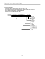
CHAPTER 2 Specification
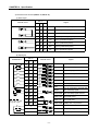
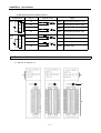
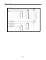
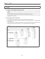
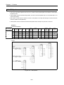
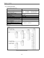
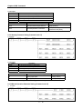
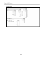
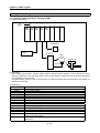
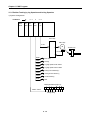
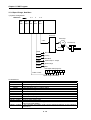
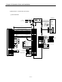
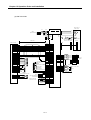
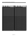
3) Internal circuit of connector(G4F-PP O, G4F-PP D)
(1) Pulse output
Pin no.
Internal circuit
Open Collector output
Line Drive output
Signal
X
Y
Z
21
41
61
FP+
Pulse F(CW/Pulse/A phase)
22
42
62
FP-
Pulse COM(CW/Pulse/A phase)
23
43
63
RP+
Pulse F(CCW/Sign/B phase)
24
44
64
RP-
Pulse COM(CCW/Sign/B phase)
21
41
61
FP+
Pulse F+(CW/Pulse/A phase)
22
42
62
FP-
Pulse F-(CW/Pulse/A phase)
23
43
63
RP+
Pulse R+(CW/Pulse/A phase)
24
44
64
RP-
Pulse R-(CW/Pulse/A phase)
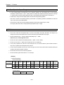
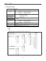
(2) Input signal
Pin no.
Classification
Internal circuit
Signal
X
Y
Z
25
45
65
OV+
26
46
66
OV-
※1
Low limit(B contact)
27
47
67
STOP
External stop signal
28
48
68
DOG
Approximate origin
29
49
69
VTP
Speed/Position switching signal
30
50
70
ECMD
External command signal
31
51
71
JOG-
Reverse jog operation
32
52
72
COM
Common
(OV+,OV-,STOP,DOG,VTP,ECMD,JOG-)
33
53
73
DRVIN
34
54
74
DRVIN COM drive Unit Ready signal Common
35
55
75
HOME +24V Zero signal (+24V)
37
57
77
HOME +5V
38
58
78
HOME COM HOME(+24V, +5V) Common
※1
DC24V
※1
High limit(B contact)
drive Unit Ready signal
DC24V
Wiring path without
using the signal
DC24V
Zero signal (+5V)
7
CON
External simultaneous start
8
EMG
Emergency stop(B contact)
10
COM
(CON, EMG)Common
※1
※1 : High/Low limit, drive Unit Ready signal, emergency stop signal should be connected to DC24V.
2-7
CHAPTER 2 Specification
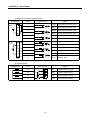
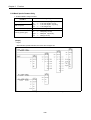
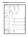
(3) Manual pulse generator input/Encoder input
Classification
Voltage
input
Pin no.
5V
DC5V
Internal circuit
Signal
1
MPG A+ Manual pulse generator A+ input
A
2
MPG A- Manual pulse generator A- input
B
3
MPG B+ Manual pulse generator B+ input
4
MPG B- Manual pulse generator B- input
5
MPG Z+ Encoder Z+ input
6
MPG Z- Encoder Z- input
1
MPG A+ Encoder A+ input
2
MPG A- Encoder A- input
3
MPG B+ Encoder B+ input
4
MPG B- Encoder B- input
5
MPG Z+ Encoder Z+ input
6
MPG Z- Encoder Z- input
0V
MPG
Line
Driver
input
A+
A-
5V
B+
DC5V
B-
0V
Z+
ZEncoder
(4) Transistor Output
Classification
Pin no.
Internal circuit
Signal
L
11
Out1
Transistor output of Zone 0
L
12
Out2
Transistor output of Zone 1
L
13
Out3
Transistor output of Zone 2
14
COM
Out1, Out2, Out3 Common
DC24V
2-8
CHAPTER 2 Specification
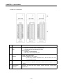
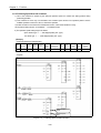
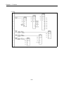
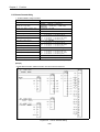
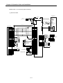
4) Internal circuit of connector(G6F-PP O, G6F-PP D)
(1) Pulse output
Pin no.
Internal circuit
Open Collector Output
Line Drive Output
Signal
X
Y
Z
21A
1B
21B
FP+
Pulse F(CW/Pulse/A phase)
22A
2B
22B
FP-
Pulse COM(CW/Pulse/A phase)
23A
3B
23B
RP+
Pulse F(CCW/Sign/B phase)
24A
4B
24B
RP-
Pulse COM(CCW/Sign/B phase)
38A
18B
38B
P COM
39A
19B
39B
5V
40A
20B
40B
24V
21A
1B
21B
FP+
Pulse F+(CW/Pulse/A phase)
22A
2B
22B
FP-
Pulse F-(CW/Pulse/A phase)
23A
3B
23B
RP+
Pulse R+(CW/Pulse/A phase)
24A
4B
24B
RP-
Pulse R-(CW/Pulse/A phase)
2-9
External 5V, 24V GND
(G6F-PP D is not used)
External 5V Power Input
(G6F-PP D is not used)
External 24V Power Input
(G6F-PP D is not used)
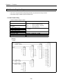
CHAPTER 2 Specification
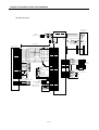
(2) Input signal
Pin no.
Classification
Internal circuit
Signal
X
Y
Z
25A
5B
25B
OV+
26A
6B
26B
OV-
※1
Low limit(B contact)
27A
7B
27B
STOP
External stop signal
28A
8B
28B
DOG
Approximate origin
29A
9B
29B
VTP
Speed/Position switching signal
30A
10B
30B
ECMD
External command signal
31A
11B
31B
JOG-
Reverse jog operation
32A
12B
32B
COM
Common
(OV+,OV-,STOP,DOG,VTP,ECMD,JOG-)
33A
13B
33B
DRVIN
34A
14B
34B
DRVIN COM drive Unit Ready signal Common
35A
15B
35B
HOME +24V Zero signal (+24V)
37A
17B
37B
HOME +5V
36A
16B
36B
HOME COM HOME(+24V, +5V) Common
※1
DC24V
※1
High limit(B contact)
drive Unit Ready signal
DC24V
Wiring path without
using the signal
DC24V
Zero signal (+5V)
7A
CON
External simultaneous start
8A
EMG
Emergency stop(B contact)
10A
COM
(CON, EMG)Common
※1
※1 : High/Low limit, drive Unit Ready signal, emergency stop signal should be connected to DC24V.
2 - 10
CHAPTER 2 Specification
(3) Manual pulse generator input/Encoder input
Classification
Voltage
input
Pin no.
Signal
1A
MPG A+ Manual pulse generator A+ input
A
2A
MPG A- Manual pulse generator A- input
B
3A
MPG B+ Manual pulse generator B+ input
4A
MPG B- Manual pulse generator B- input
1A
MPG A+ Encoder A+ input
2A
MPG A- Encoder A- input
3A
MPG B+ Encoder B+ input
4A
MPG B- Encoder B- input
5V
DC5V
Internal circuit
0V
MPG
Line
Driver
input
A+
5V
A-
B+
DC5V
B0V
Encoder
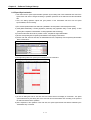
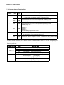
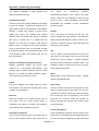
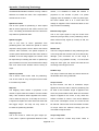
2.4 The Name and Function of each Section
1) G4F-PP O, G4F-PP D
②
①
③
④
2 - 11
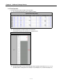
CHAPTER 2 Specification
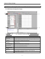
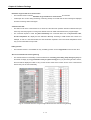
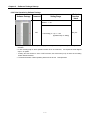
2) G6F-PP O, G6F-PP D
No.
①
②
③
Name
Description
1. Operation indication
▶Light-On: In operation of the corresponding axis
LED
▶Light-Off: When the corresponding axis stops
2. Error indication
▶Light-On : In normal operation
▶Blink: Error of the corresponding axis
: Operation stop
▶STOP
Operation information
▶RUN :Nnormal operation
indicator
▶EXXX : Indication of error no. XXX
(At this time, operation indication LED of the axis where the error
occurred begins to blink.)
Selected
the
information of operation information indicator
Mode switch
▶The information of operation information indicator will be changed at each
Operation indication
press.
④
External wiring
Connector to connect with drive machine, machine field input, manual pulse
connector
generator etc.
2 - 12
CHAPTER 2 Specification
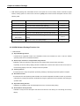
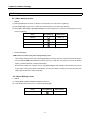
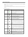
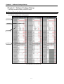
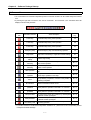
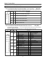
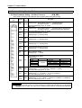
3) Relation of Operation information indicator and Mode switch
Operation
information
Description
indicator
Self diagnosis indication when power ON
INIT
Mode switch
INIT
Operation indication
▶ information indication in operation
(The corresponding axis LED light-on : in operation
light-off : stop)
operation state indication
per axis
▶ indicated one from 3 modes
STOP
Waiting state for operation
RUN
In operation
STOP
Waiting state for operation
BUSY
In operation
EXXX
Error no. indication
NOP
Operation stop
POS
1 axis position control operation
CON
Simultaneous start operation
ORG
Origin return operation
VTP
Speed/Position conversion operation
PTV
Position/Speed conversion operation
SSP
Position synchronous start
SSS
Speed synchronous start
MPG
Manual pulse operation
JGH
JGH
Jog high speed operation
JGL
JGL
Jog low speed operation
INC
INC
Inching operation
RTP
RTP
Return to the position before manual
operation
EMG
Emergency stop
STOP
Operation stop
STOP
RUN
STOP
BUSY
EXXX
operation command
indication
▶ indicated one from 14 operation types
NOP
POS
CON
ORG
VTP
PTV
▶ action repeat per axis
SSP
SSS
MPG
EMG
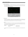
speed section indication
STOP
▶ indicated one from 4 speed patterns
ACC
EQU
DEC
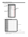
input signal indication
▶9 external input state indication
(The corresponding axis LED light-on : external input “ON”
light-off : external input “OFF”)
HOME
RDY
ECMD
ULMT
LLMT
DOG
SSRT
ESTP
EVTP
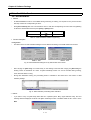
Zone output state indication
▶ LED light-on : in external output
LED light-off : no external output
O/S version indication
ACC
Accelerating operation
EQU
Equal speed operation
DEC
Decelerating operation
HOME
RDY
Home signal input
Driver Ready signal input
ECMD
External command signal input
ULMT
Upper Limit signal input
LLMT
Lower Limit signal input
DOG
Dog signal input
SSRT
External simultaneous start signal input
ESTP
External stop signal input
EVTP
External VTP signal input
ZONE
ZONE output
VX.X
Version information
2 - 13
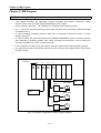
Chapter 3 Function
Chapter 3
Function
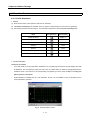
3.1 Positioning Control
Positioning Control includes position control, interpolation control, speed control, speed/position conversion
control, position/speed conversion control.
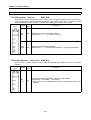
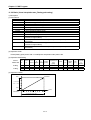
3.1.1 Position Control
Positioning control from start address (present stop position) to goal address (transfer amount) for the
assigned axis.
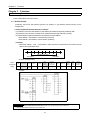
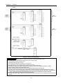
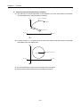
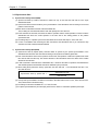
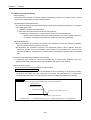
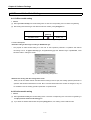
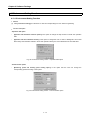
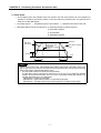
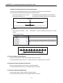
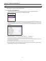
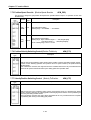
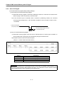
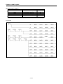
1) Control by Absolute method (Absolute coordinate)
(1) Positioning control from start address to goal address (the address assigned by positioning data).
(2) Positioning control is carried out based on the address assigned (origin address) by homing.
(3) Transfer direction shall be determined by start address and goal address.
▶Start address < Goal address : normal direction positioning
▶Start address > Goal address : reverse direction positioning
[ Example ]
▷When Start address : 1000, ▷Goal address : 8000, this will be normal direction and transfer amount
shall be 7000 (7000=8000-1000).
0
1000
8000
Transfer amount: 7000
Goal address
Start address
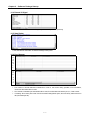
▷Software Package setting
Coordinate
position data
Step
No.
Control
method
Operation
pattern
Operation
method
Goal
position
[pulse]
Circular
interpolation aux.
Point [pulse]
Setting
1
Absolute
Position
control
End
Single
8000
0
Items of
M
code
0
Acce./
dece. No.
Operation
speed
[pls/s]
Dwell
time
[㎳]
Circular
interpolation
direction
1
100
0
CW
▷Program
Error
information
Operation
information
Program 3.1 Basic(Floating point setting)
Point
▶A control by Absolute method (Absolute coordinate) shall start only in the state that the origin is determined.
▶If starting without determining the origin, error 234 will occur.
3-1
Chapter 3 Function
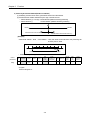
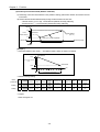
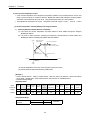
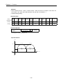
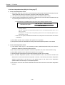
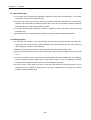
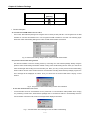
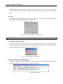
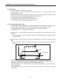
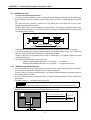
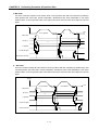
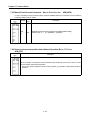
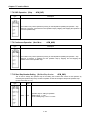
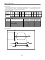
2) Control by Incremental method (Relative coordinate)
(1) Positioning control as much as the goal transfer amount from start address.
(2) Transfer direction shall be determined by the sign of transfer amount.
▷Transfer direction (+) or no sign : normal direction (address increase) positioning
: reverse direction (address decrease) positioning
▷Transfer direction( - )
Start Address
Normal
Reverse
Transfer direction when transfer amount (-)
Transfer direction when transfer amount (+)
[Example]
▷When Start address : 5000, ▷Goal address : -7000, this will be reverse direction and positioning will
be at the point of –2000.
-2000
0
5000
Reverse positioning control (transfer amount-7000)
Goal address
Start address
▷ Software Package Setting
Coordinate
position data
Step
No.
Control
method
Operation
pattern
Operation
method
Goal
position
[pulse]
Circular
interpolation aux.
Point [pulse]
M
code
Acce./
dece. No.
Operation
speed
[pls/s]
Dwell
time
[㎳]
Circular
interpolation
direction
Setting
1
Incremental
Position
control
End
Single
-7000
0
0
1
100
0
CW
Items of
▷Program
Same as Program 3.1.
3-2
Chapter 3 Function
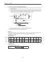
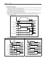
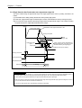
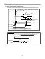
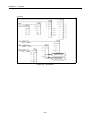
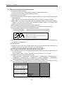
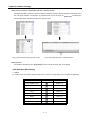
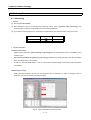
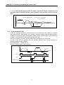
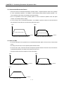
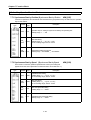
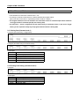
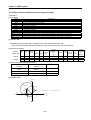
3.1.2 Interpolation Control
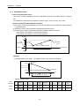
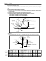
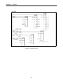
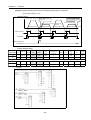
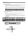
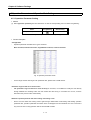
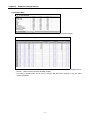
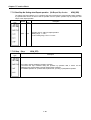
1) 2 axis linear interpolation control
This carries out Linear interpolation control at the start address (present stop position) using the 2 assigned
axis.
The available axis combinations for interpolation control are 3 types : X and Y, X and Z , and Y and Z.
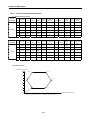
(1) Control by Absolute method (Absolute coordinate)
A) This carries out the linear interpolation by 2 axis from Start address to Goal address (the address assigned
by positioning data).
B) Positioning control is carried out based on the address assigned by homing.
C) Transfer direction shall be determined by Start address and Goal address of each axis.
▶Start address < Goal address : normal direction positioning
▶Start address > Goal address : reverse direction positioning
Normal (Y)
Y2
Y axis
transfer amount
Start address
(X1, Y1)
Goal address
(X2, Y2)
Y1
Action by X,Y linear interpolation
Reverse
Normal (X axis)
X axis transfer amount
X1
X2
Reverse
[Example]
▷When Start address (1000, 4000), ▷Goal address (10000, 1000), the action is as follows.
(Y)
4000
Start address
Y axis transfer amount
(1000-4000=-3000)
Goal address
1000
(X)
0
1000
5000
10000
X axis transfer amount (10000-1000=9000)
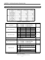
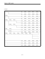
▷ Software Package Setting
Items of
Step
No.
Coordinate
X Setting
1
Absolute
Y Setting
1
Absolute
position data
Control
method
Position
control
Position
control
Operation
pattern
Operation
method
Goal
position
[pulse]
Circular
interpolation aux.
Point [pulse]
M
code
Acce./
dece. No.
Operation
speed
[pls/s]
Dwell
time
[㎳]
Circular
interpolation
direction
End
Single
10000
0
0
1
100
0
CW
End
Single
1000
0
0
1
100
0
CW
3-3
Chapter 3 Function
▷Program
Release of
prohibited
output if
error occurs
X axis
information
Release of
prohibited
output if
error occurs
Y axis
information
X Axis operation X axis error
information
information
Y axis operation Y axis error
information
information
X Axis operation X axis error
information
information
Y axis positioning
information
X axis positioning Y axis operation Y axis error
information
information
information
Program 3.2 Basic (Linear interpolation)
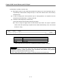
Point
As at the linear interpolation start, 2 or 3 axis act synchronously, cares should be taken in using.
1) The available operation pattern is End, Go-on and operation method is Single, Repeat.
If set as Continuous, it shall be processed as End.
2) The available auxiliary operation is as follows.
Speed override, Stop, Emergency stop, Skip, Zone output permitted,
3) The command that is not used at the linear interpolation operation is as follows.
Position/Speed switching control, Position override, Continuous operation, Position/Speed override.
4) The auxiliary data related to the operation that acts based on the main axis during linear interpolation operation is as follows.
Operation method, operation pattern, Speed limit, Dwell time,
5) The main and subordinate axis shall be determined by the positioning address amount of operation step.
(1) main axis : the axis whose positioning address amount of the corresponding operation step number is bigger among X, Y, Z axis.
(2) subordinate axis : the axis whose positioning address amount of the corresponding operation step number is smaller among X,
Y, Z axis. ; At this time, the speed, acceleration/deceleration time, bias speed of the subordinate axis shall be recalculated.
6 ) The items that acts based on the setting value of each axis are as follows.
; Backlash compensation amount, Software high limit, Software low limit, Position pass time, Zone setting area among the items of
parameter
3-4
Chapter 3 Function
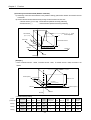
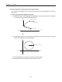
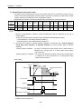
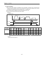
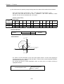
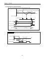
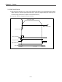
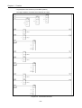
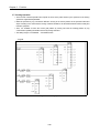
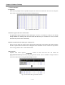
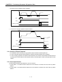
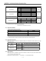
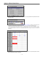
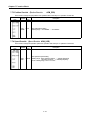
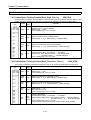
(2) Control by Incremental method (Relative coordinate)
A) Positioning control from start address to the position including goal transfer direction and transfer amount
of each axis.
B) Transfer direction shall be determined by the sign of transfer amount of each axis.
- Transfer amount (+) or no sign : normal direction (address increase) positioning
- Transfer amount ( - ) : reverse direction (address decrease) positioning
Normal (Y)
Y2
Start address
(X1, Y1)
Y axis
transfer amount
Goal address
(X2, Y2)
Y1
Action by X, Y linear interpolation
Normal (X axis)
Reverse
X1
X axis transfer amount
X2
Reverse
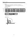
[ Example ]
▷When Start address (1000, 4000), ▷Goal address (9000, -3000), the action is as follows.
(Y)
Start address
4000
Y axis transfer amount
(-3000)
Goal address
1000
(X)
0
1000
5000
10000
X axis transfer amount (9000)
▷Software Package Setting
Coordinate
position data
Step
no.
Control
method
Operation
pattern
Operation
method
Goal
position
[pulse]
Circular
interpolation aux.
Point [pulse]
M
code
Acce./
dece. No.
Operation
speed
[pls/s]
Dwell
time
[㎳]
Circular
interpolation
direction
X Setting
1
Incremental
Position
control
End
Single
9000
0
0
1
100
0
CW
Y Setting
1
Incremental
Position
control
End
Single
-3000
0
0
1
100
0
CW
Items of
▷Program
Same as Program 3.2.
3-5
Chapter 3 Function
2) 3 axis Linear Interpolation Control
This carries out the linear interpolation control from Start address (present stop position) using 3 assigned
axis.
(1) Control by Absolute method (Absolute coordinate)
A) This carries out the linear interpolation by 3 axis from Start address to Goal address (the address assigned
by positioning data).
B) Positioning control is carried out based on the address assigned by homing.
C) Transfer direction shall be determined by Start address and Goal address of each axis.
▶Start address < Goal address : normal direction positioning
▶Start address > Goal address : reverse direction positioning
Normal (Y)
Goal address
(X2, Y2, Z2)
Action by X, Y, Z
Linear interpolation
Start address
(X1, Y1, Z1)
Y2
Z2
Normal (Z)
Y axis transfer amount
Z axis
transfer amount
Y1
Z1
Reverse
X axis transfer amount
X1
Normal (X)
X2
Reverse
Reverse
[ Example ]
▷When Start address (2000, 1000, 1000 ), ▷Goal address (5000, 5000, 4000), the action is as follows.
Normal (axis2)
Goal address
Positioning address
6000
Normal (axis3)
Axis2 transfer amount
(6000-1000=5000)
Axis3 transfer amount
(4000-1000=3000)
Start address
(present stop position)
4000
1000
1000
Normal (axis1)
Reverse
2000
5000
Axis1 transfer amount
(5000-2000=3000)
Reverse
Reverse
▷Software Package Setting
Items of
Coordinate
position data
Step
no.
X Setting
1
Absolute
Y Setting
1
Absolute
Z Setting
1
Absolute
Control
method
Position
control
Position
control
Position
control
Operation
pattern
Operation
method
Goal
position
[pulse]
Circular
interpolation aux.
Point [pulse]
M
code
Acce./
dece. No.
Operation
speed
[pls/s]
Dwell
time
[㎳]
Circular
interpolation
direction
End
Single
5000
0
0
1
100
0
CW
End
Single
6000
0
0
1
100
0
CW
End
Single
4000
0
0
1
100
0
CW
3-6
Chapter 3 Function
(2) Control by Incremental method (Relative coordinate)
A) Positioning control from start address to the position including goal transfer direction and transfer amount
of each axis.
B) Transfer direction shall be determined by the sign of transfer amount of each axis.
- Transfer amount (+) or no sign : normal direction (address increase) positioning
- Transfer amount ( - )
: reverse direction (address decrease) positioning
Normal (Y)
Action by X, Y, Z axis
linear interpolation
Start address
(X1, Y1, Z1)
Y2
Z2
Normal (Z)
Y axis transfer amount
Z axis
transfer amount
Y1
Z1
Reverse
X axis transfer amount
X1
Normal (X)
X2
Reverse
Reverse
[ Example ]
▷When X transfer amount : 10000, Y transfer amount : 5000, Z transfer amount : 5000, the action is as
follows.
Normal (axis2)
Normal (axis3)
Axis3 transfer amount
(5000)
Stop address after positioning
completion
5000
Axis2 transfer amount
(5000)
5000
Start address
(present stop position)
Axis1 transfer amount (10000)
Normal (axis1)
Reverse
5000
10000
Reverse
Reverse
▷Software Package Setting
Coordinate
position data
Step
no.
Control
method
Operation
pattern
Operation
method
Goal
position
[pulse]
Circular
interpolation aux.
Point [pulse]
M
code
Acce./
dece. No.
Operation
speed
[pls/s]
Dwell
time
[㎳]
Circular
interpolation
direction
X Setting
1
Absolute
Position
control
End
Single
10000
0
0
1
100
0
CW
Y Setting
1
Absolute
Position
control
End
Single
5000
0
0
1
100
0
CW
Z Setting
1
Absolute
Position
control
End
Single
5000
0
0
1
100
0
CW
Items of
3-7
Chapter 3 Function
The Program is same as Program 3.2.
3-8
Chapter 3 Function
3) 2 axis Circular interpolation control
▶2 axis circular interpolation control begins the interpolation operation to the traveling direction of each axis
using 2 motors and there are 2 kinds of methods : Middle point method that passes the assigned position
and Center Point method that acts as an circle using the assigned position as a center position.
▶The available axis combination for circular interpolation control are 3 types : X and Y, X and Z, Y and Z.
(1) Circular interpolation control by Middle point assigned method
1)
Control by Absolute method (Absolute coordinate)
(A) This carries out Circular interpolation from Start address to Goal address through the assigned
Middle point address.
(B) The circle is made around the crossing point created by vertical bisection of Start address and
Middle point address or Middle point address and Goal address.
Middle point address
(Circle address)
Normal
Action by circle interpolation
Goal address
(Positioning address)
Start address
(present stop position)
Center point of circle
Reverse
Normal
Origin
Reverse
(C) Circular interpolation control can not be used with control unit “Degree”.
(D) Transfer direction shall be determined by APM module
[ Example ]
▷When X transfer amount : 13000, Y transfer amount : 9000, the action is as follows in case that X auxiliary
point :10000, Y auxiliary point :7500, rotation direction :CW, main axis :X, subordinate axis :Y.
▷Software Package Setting
<Operation Data>
Items of
Coordinate
position data
Step
no.
X Setting
1
Absolute
Y Setting
1
Absolute
Control
method
Position
control
Position
control
Operation
pattern
Operation
method
Goal
position
[pulse]
Circular
interpolation aux.
Point [pulse]
M
code
Acce./
dece. No.
Operation
speed
[pls/s]
Dwell
time
[㎳]
Circular
interpolation
direction
End
Single
13000
10000
0
1
1000
0
CW
End
Single
9000
7500
0
1
1000
0
CW
<Command window>
Circular interpolation
operation
Step
Subordinate axis
1
Y
3-9
Execution
Chapter 3 Function
▷Program
Release of
prohibited
output if
error occurs
X axis
information
Release of
prohibited
output if
error occurs
Y axis
information
Home position
return
X axis operation
information
X axis error
information
X axis positioning Y axis error
information
information
Y axis operation
information
Y axis positioning
information
Program 3.3 Basic (Circular interpolation)
Point
As at Circular interpolationstart 2 axis act synchronously, cares should be taken.
1) The available operation pattern is End, Go-on and the operation method is Single, Repeat.
If set as Continuous, it shall be processed “Go-on”.
2) The available auxiliary operation is as follows.
Speed override,Stop, Emergency stop, Zone output permitted,
3) The command that is not used at the linear interpolation operation is as follows.
Position/Speed switching control, Position override, Continuous operation, Position/Speed override
4) The auxiliary data related to the operation that acts based on the main axis during linear interpolation operation is as follows.
Operation method, operation pattern, Speed limit, Dwell time,
5) The items that acts based on the setting value of each axis are as follows.
; Backlash compensation amount, Software high limit, Software low limit, Position pass time, Zone setting area among the
items of parameter
3-10
Chapter 3 Function
2)
Control by Incremental method (Relative coordinate)
(A) This carries out the circular interpolation from Start address to Goal address through the assigned
middle point address.
(B) The circle is made around the crossing point created by dividing the Middle point address calculated
by transfer amount from Start address to Middle point address and Goal address calculated by
transfer amount from Middle point address to Goal address into two vertically.
Normal
Action by circle interpolation
Middle point address
Goal address
Transfer amount to
Middle point address
Transfer amount to
Goal address
Start address
Center point of circle
Reverse
Normal
Reverse
Transfer amount to
Middle point address
Transfer amount to Goal address
(C) Circular interpolation control can not be used with control unit “Degree”.
(D) Transfer direction shall be determined by APM module
[ Example ]
▷When X transfer amount : 13000, Y transfer amount : 9000, the action is as follows in case that X aux.
Point :10000, Y aux. point: 7500, rotation direction: CW, main axis: X, subordinate axis: Y.
▷Software Package Setting
<Operation Data>
Items of position
Coordinate
data
Step
no.
X Setting
1
Relative
Y Setting
1
Relative
Control
method
Position
control
Position
control
Operation
pattern
Operation
method
Goal
position
[pulse]
Circular
interpolation aux.
Point [pulse]
M
code
Acce./
dece. No.
Operation
speed
[pls/s]
Dwell
time
[㎳]
Circular
interpolation
direction
End
Single
13000
10000
0
1
1000
0
CW
End
Single
9000
7500
0
1
1000
0
CW
<Command Window>
The Program is same as Program 3.3.
Circular interpolation
operation
Step
Subordinate axis
1
Y
3-11
Execution
Chapter 3 Function
(2) Circular interpolation control by Center point assigned method
This is the Circular interpolation control to assign the Goal address of circular interpolation and the center
point of circle.
1) Control by Absolute method (Absolute coordinate)
(A) This carries out the circular interpolation to Goal address by the circle whose radius is the distance
from Start address to the assigned Middle point address.
Normal
Action by circle interpolation
Goal address
Radius
Center point of circle
Reverse
Normal
Reverse
(B) If Goal address equals to the Start address, the positioning for the circle whose radius is from Start
address to the center point of circle shall be done.
Normal
Center point of circle
Reverse
Start address = Goal address
Normal
Reverse
(C) Circular interpolation control can be not used with control unit “Degree”.
(D) Transfer direction shall be determined by S/W package or Program.
3-12
Chapter 3 Function
[Example ]
▷When X current position : 0, X goal position : 0, Y current position : 0, Y goal position : 0,
the action is as follows in case that X aux. Point : 1000, Y aux. Point : 1000, rotation direction : CW,
main axis : X, subordinate axis : Y.
▷Software Package Setting
<Operation Data>
Coordinate
data
Step
no.
Control
method
Operation
pattern
Operation
method
Goal
position
[pulse]
Circular
interpolation aux.
Point [pulse]
M
code
Acce./
dece. No.
Operation
speed
[pls/s]
Dwell
time
[㎳]
Circular
interpolation
direction
X Setting
1
Absolute
Position
control
End
Single
0
1000
0
1
100
0
CW
Y Setting
1
Absolute
Position
control
End
Single
0
1000
0
1
100
0
CW
Items of position
<Command Window>
Circular interpolation
operation
Step
Subordinate axis
1
Y
Execution
The Program is same as Program 3.3.
<Operation Pattern>
Y axis
(1000,1000)
1000
0
X axis
0
1000
3-13
Chapter 3 Function
2)
Control by Incremental method (Relative coordinate)
(A) This carries out the Circular interpolation to Goal address by the circle whose radius is the distance
from Start address to the assigned Middle point address.
Normal
Action by circle interpolation
Goal address
Radius
Center point of circle
Reverse
Normal
Reverse
(B) If transfer amount is “0”, the positioning of the circle whose radius is from Start address to the Middle
point address of the circle shall be done.
Normal
Center point of circle
Reverse
Start address = Goal address
Normal
Reverse
(C) The circular interpolation control cannot be used with control unit “Degree”.
(D) Transfer direction shall be determined by S/W package and Program.
3-14
Chapter 3 Function
[Example ]
▷When X transfer amount : 13000, Y transfer amount : 9000, the action is as follows in case that X aux.
Point :10000, Y aux. point: 7500, rotation direction :CW, main axis :X, subordinate : Y.
▷Software Package Setting
<Operation Data>
Coordinate
position data
Step
no.
Control
method
Operation
pattern
Operation
method
Goal
position
[pulse]
Circular
interpolation aux.
Point [pulse]
M
code
Acce./
dece. No.
Operation
speed
[pls/s]
Dwell
time
[㎳]
Circular
interpolation
direction
X Setting
1
Relative
Position
control
End
Single
13000
10000
0
1
100
0
CW
Y Setting
1
Relative
Position
control
End
Single
9000
7500
0
1
100
0
CW
Items of
<Command Window>
Circular interpolation
operation
Step
Subordinate axis
1
Y
Execution
The Program is same as Program 3.3.
<Operation Pattern>
Y axis
1’st start
2’nd start
( 1000, 0 )
( 3000, 0 )
1000
0
0
4000
2000
3-15
X axis
Chapter 3 Function
3.1.3 Speed Control (Equal Speed Operation)
▶This controls the speed by the setting speed until deceleration stop command is entered after execution by
positioning start.
(If the operation stops by deceleration stop command, it becomes “origin unsettled state”.)
▶Speed control contains 2 types of start : Normal direction start and Reverse direction start.
▷Normal direction : when position address is positive number (+) (“0” included)
▷Reverse direction : when position address is negative number (-)
▶In case of using speed control, the following items of positioning data does not effect.
Items of
Step
no.
Position Data
Coordinate
Control
method
Operation
pattern
Operation
method
Goal
position
[pulse]
Circular
interpolation aux.
Point [pulse]
M
code
Acce/
dece. No.
Operation
speed
[pls/s]
Dwell
time
[㎳]
Circular
interpolation
direction
Items that does not effect
▶In case of using M code, please use only “With” mode.
(If using “After” mode, M code “ON” signal does not output.)
▶In case of changing the operation step no., it is required to use “Start step no assignment”.
▶When using the current position during operation, it is required to set “Position during Equal speed
operation” from “Extended parameter” of S/W Package as “Indication”.
(The current position can be displayed only in the state that the origin is determined.)
▶Action Timing
Speed
Setting speed
Dwell time
Time
On
Start command
On
In operation
It does not “ON”
even if stop
Positioning end signal
On
Deceleration stop command
[ Example ]
▷Software Package Setting
Coordinate
Setting
Step
no.
Control
method
Operation
pattern
Operation
method
Goal
position
[pulse]
Circular
interpolation aux.
Point [pulse]
M
code
Acc./
dece. No.
Operation
speed
[pls/s]
Dwell
time
[㎳]
Circular
interpolation
direction
Normal
1
Absolute
Speed
control
Go-on
Single
100
0
1
1
1000
0
CW
Reverse
2
Absolute
Speed
control
End
Repeat
-100
0
2
1
2000
0
CW
Direction
3-16
Chapter 3 Function
▷Program
Axis operation Axis error
information
information
Axis operation
information
Axis error
information
Axis error
information
Axis operation
information
Used when changing the operation step
Command to stop the operation when
acting with speed control
Program 3.4 Speed Control
3-17
Chapter 3 Function
3.1.4 Speed/Position Conversion Control
▶The setting axis by positioning start carries out the speed control and is converted from speed control to
position control when speed/position conversion signal is entered to the positioning module inside or outside,
and then carries out the positioning as much as goal transfer amount.
▶Speed/Position Conversion control can be operated to the normal direction and reverse direction.
Coordinate
Setting
Step
no.
Control
method
Operation
pattern
Operation
method
Goal
position
[pulse]
Circular
interpolation aux.
Point [pulse]
M
code
Acc./
dec.No.
Operation
speed
[pls/s]
Dwell
time
[㎳]
Circle
interpolation
direction
Normal
1
Relative
Speed
Go-on
Single
1000
0
1
1
1000
100
CW
Reverse
2
Relative
Speed
End
Repeat
-1000
0
2
1
2000
100
CW
Direction
The item that does
not effect
▷Direction of Speed/Position conversion control (normal/reverse) shall be determined by the sign of
position address.
(In this case, all is processed by Absolute method regardless of Absolute/Relative method.)
*1 (normal direction) : when position address is positive (+)
*2 (reverse direction) : when position address is negative (-)
▶0…According to the selection of position indication (“indication”/”no indication”) from “Position Indication
during Equal speed operation” of Extended parameter, the current position shall be indicated
differently.
Position indication “indication” : The origin is determined at speed control and the current position is
indicated and it operates from “0” to Goal position during position
control conversion
Position indication “no indication” : The origin is not determined at speed control and the current position
is s indicated as “0” and it operates from “0” to Goal position during
position control conversion.
▶Action Timing
Speed
Acceleration section
Speed
control
Setting speed
Position
control
Assigned transfer amount
Dwell time
Time
On
Start command
On
In operation
On
Speed/Position conversion signal
(External input signal)
On
Speed/Position conversion signal
▷Program
Program is same as Program 3.4.
3-18
Chapter 3 Function
3.1.5 Position/Speed Conversion Control
▶The setting axis by positioning start carries out the position control and is converted from position control to
speed control when position/speed conversion signal is entered to the positioning module inside, and then it
stops by deceleration stop or SKIP operation or continues next operation.
▶Position/Speed Conversion control can be operated to the normal direction and reverse direction.
Coordinate
Setting
Step
no.
Control
method
Operation
pattern
Operation
method
Goal
position
[pulse]
Circular
interpolation aux.
Point [pulse]
M
code
Acc./
Dec. No.
Operation
speed
[pls/s]
Dwell
time
[㎳]
Circle
interpolation
direction
Normal
1
Absolute
Speed
Go-on
Single
10000
0
1
1
500
100
CW
Reverse
2
Absolute
Speed
End
Repeat
-10000
0
2
1
600
200
CW
Direction
The item that does
not effect
▷The direction of Position/Speed conversion control (normal/reverse) shall be determined by the sign of
position address.
*1 (normal direction) : when position address is positive(+)
*2 (reverse direction) : when position address is negative(-)
▶Action Timing
Speed
Acceleration section
Position
control
Speed
control
Setting speed
Dwell time
Time
On
Start command
On
In operation
On
Internal Position/Speed
conversion signal
On
Deceleration stop command
3-19
Chapter 3 Function
▷Program
Axis operation
information
Axis error
information
Axis operation
information
Axis error
information
Axis operation
information
Axis error
information
Command to stop the operation when acting with
speed control
Program 3.5 Position/Speed Conversion Control
3-20
Chapter 3 Function
3.2 Operation Mode
▶Operation mode describes various configuration for how to operate the positioning data using several operation
step no and how to determine the speed of position data.
▶Operation mode types are as follows.
Control
Operation
Operation
Others
method
pattern
method
End
Single
End
Repeat
Go-on
Single
Position
control
Go-on
Repeat
Continuous
Single
■Linear/Circular interpolation function is not used.
Continuous
Repeat
■Linear/Circular interpolation function is not used.
Speed control
End
Single
■Linear/Circular interpolation function is not used.
Go-on
Continuous
Single
Repeat
■not available
▶Operation mode shall be set from PLC Program or Operation data of Software Package.
▶Operation data can be set by max. 400 from operation step no. 1 ~ 400 at each axis.
Type of
Operation data
Setting
range/Type
Step
no.
Coordinate
Control
method
Operation
pattern
Operation
method
Goal
position
[pulse]
Circular
interpolation aux.
Point [pulse]
M
code
Acc./
dec. No.
Operation
speed
[pls/s]
Dwell
time
[㎳]
Circle
interpolation
direction
1
~
400
Absolute
relative
Position
speed
End
go-on
conti.
Single
repeat
2147483648
~
2147483647
-2147483648
~
2147483647
0
~
65535
1
~
4
0
~
1000000
0
~
50000
CW,CCW
▶With one time start command, positioning operation method by one operation step positioning data and
positioning operation method by several operation step in order shall be determined by operation mode of each
positioning data set by the operator.
3-21
Chapter 3 Function
3.2.1 End Operation (Single)
1) With one time start command, the positioning to the goal position is executed and the positioning shall be
completed at the same time as the dwell time proceeds.
2) The positioning completion of this operation mode can be used as operation mode of last positioning data of
Go-on operation mode and Continuous operation mode.
3) Operation direction shall be determined by position address.
4) Operation action is trapezoid type operation that has acceleration, constant, deceleration section according to
the setting speed and position data but the operation pattern according to the setting value is as follows.
a) Normal operation pattern
Speed
Dwell time
Time
On
Start command
On
In operation
On
In acceleration
On
In constant speed
On
In deceleration
On
In dwell
On
Positioning completion
b) Abnormal operation pattern
When operation speed is set as “higher” than position transfer amount
Speed
When operation speed is set as same as bias speed
Speed
Dwell time
Time
On
Start command
In operation
In deceleration
Time
On
Start command
On
On
In operation
On
In acceleration
In acceleration
In constant speed
Dwell time
Bias speed
On
In constant speed
On
In deceleration
On
Dwell time
Dwell time
On
Positioning
completion
Positioning
completion
3-22
On
On
Chapter 3 Function
[ Example ]
▷ Operation pattern
Speed
Operation mode : End
Operation mode : End
Operation mode : End
Operation step no.: 1
Operation mode : End
Operation step no.: 3
Operation step no.: 2
Operation step no.: 4
On
Start command
On
In operation
▷Software Package Setting
Step
Coordinate
No.
Control
method
Operation
pattern
Operation
method
Goal
position
[pulse]
Circular
interpolation aux.
point [pulse]
M
code
Acc./
dec. No.
Operation
speed
[pls/s]
Dwell
time
[㎳]
Circle
interpolation
direction
1
Absolute
Position
End
Single
10000
0
0
1
1000
0
CW
2
Absolute
Position
End
Single
20000
0
0
1
500
0
CW
3
Absolute
Position
End
Single
30000
0
0
1
1000
0
CW
4
Absolute
Position
End
Single
40000
0
0
1
500
0
CW
▷Program
Axis operation Axis error
information
information
Axis operation Axis error
information
information
Program 3.6 End Operation (Homing)
3-23
Time
Chapter 3 Function
3.2.2 End Operation (Repeat)
1) With one time start command, the positioning to the goal position is executed and the positioning shall be
completed at the same time as the dwell time proceeds.
2) The operation type of Repeat operation mode is same as that of Single operation but the different thing is to
determine next operation by operation step no. assigned by repeat step no. change command after positioning
completion of Repeat operation mode.
3) Therefore, if Repeat step no. change command was not executed, the step no.“1” shall be assigned after
positioning completion of Repeat operation mode and operated at next Start command. Thus, this operation
can be used for the structure that several operation steps are repeated.
4) In case that operation step is set as the value except “0” (1~400) when Indirect Start, the positioning operation
shall be done with the setting step no. regardless of the current operation step no. But, if the step no. is set as
“0”, the positioning operation shall be done with the current step no. changed by Repeat operation mode.
5) Operation direction shall be determined by position address.
6) Repeat operation step no. change command is available to execute during operation.
[Example 1 ] When operating only by Start Command [In the case of step no = “0”]
▷ Operation Pattern
Speed
As operation step no. has
not changed after repeat
operation, it operates
step no.”1” again.
Operation mode : End (single)
Operation mode : End (single)
Operation mode : End (repeat)
Operation mode : End (repeat)
Operation step no.: 1
Operation step no.: 2
Operation step no.: 1
Operation step no.: 2
Time
On
Start command
On
In operation
▷ Software Package Setting
Coordinate
Control
method
Operation
pattern
Operation
method
Goal
position
[pulse]
Circular
interpolation aux.
point [pulse]
M
code
Acc./
dec. No.
Operation
speed
[pls/s]
Dwell
time
[㎳]
Circle
interpolation
direction
1
Absolute
Position
End
Single
10000
0
0
1
1000
0
CW
2
Absolute
Position
End
Repeat
20000
0
0
1
500
0
CW
3
Absolute
Position
End
Single
30000
0
0
1
2000
0
CW
4
Absolute
Position
End
Repeat
40000
0
0
1
3000
0
CW
No. of program
start command
Step
no.
1, 3
2, 4
Operation step 3, 4 does not start.
▷Program
Program is same as Program 3.6.
3-24
Chapter 3 Function
[Example 2 ] When operating Start command and Repeat operation step no. assignment
[In the case of step no = “0”]
▷ Operation Pattern
Speed
Operation mode : End (single)
If continued to operate by start
command, it operates operation
step no. 3=>4 repeately.
Repeat operation step no.
assignment: 3
Operation mode : End (repeat)
Operation mode :
Operation mode : End (repeat)
End (single)
Operation step no: 1
Operation step no: 2
Operation step no: 3
Operation step no: 4
Time
On
Start command
On
In Operation
On
Repeat operation step
no. assignment
▷ Software Package Setting
No. of program
start command
Step
no.
Coordinate
Control
method
Operation
pattern
Operation
method
Goal
position
[pulse]
Circular
interpolation aux.
Point [pulse]
M
code
Acc./de
c no.
Operation
speed
[pls/s]
Dwell time
[㎳]
Circle
interpolatio
n direction
1, 3
1
Absolute
Position
End
Single
10000
0
0
1
1000
0
CW
2, 4
2
Absolute
Position
End
Repeat
20000
0
0
1
500
0
CW
The change of the number by Repeat operation step no. assignment [APM_SRS: rising edge ↑]
3
Absolute
Position
End
Single
30000
0
0
1
2000
0
CW
4
Absolute
Position
End
Repet
40000
0
0
1
3000
0
CW
▷Program
Axis operation Axis error
information
information
Axis operation Axis error
information
information
Axis error
information
Program 3.7 End Operation(Repeat operation step no. change)
3-25
Chapter 3 Function
3.2.3 Go-on Operation
1) With one time Start command, the positioning to the goal position of operation step is executed and the
positioning shall be completed at the same time as dwell time proceeds and without additional start command,
the positioning of operation step for (current operation step no. +1) shall be done.
2) Go-on operation mode is available to execute several operation step in order.
3) Operation direction shall be determined by position address.
[ Example ]
▷ Operation Pattern
Speed
Start operation step no.: 1
Dwell time
Operation mode : Go-on
Operation step no: 1
Dwell time
Operation mode :
Go-on
Operation step no: 2
Operation mode : End
Operation step no: 3
Operation mode : End
Operation step no: 4
Time
On
Start command
On
in Operation
▷Software Package Setting
No. of program
start command
1
2
Step
no.
Coordinate
Control
method
Operation
pattern
Operation
method
Goal
position
[pulse]
Circular
interpolation aux.
Point [pulse]
M
code
Acc./
dec no.
Operation
speed
[pls/s]
Dwell
time
[㎳]
Circle
interpolation
direction
1
Absolute
Position
Go-on
Single
10000
0
0
1
1000
0
CW
2
Absolute
Position
Go-on
Single
20000
0
0
1
500
0
CW
3
Absolute
Position
End
Single
30000
0
0
1
800
0
CW
4
Absolute
Position
End
Single
40000
0
0
1
500
0
CW
▷Program
Program is same as Program 3.6.
3-26
Chapter 3 Function
3.2.4 Continuous Operation
1)
2)
3)
4)
With one time Start command, the positioning for operation step set by continuous operation mode is
executed to the goal position without stop and the positioning shall be completed at the same time as dwell
time proceeds.
If you want to operate with the position and speed of next step before the operation step that is active
currently reaches the goal position, the operation by Next Move continuous operation command is available.
With Next Move continuous operation command, the operation in the acceleration, constant speed,
deceleration section of Continuous operation is available.
Operation direction shall be determined by position address.
[ Example ]
▷ Operation Pattern
Speed
Operation mode : End (repeat)
Operation step no: 2
Operation mode : Continuous
Operation step no : 1
Start command
Time
On
In Operation
▷Software Package Setting
No. of program
start command
Step
no.
Coordinate
Control
method
Operation
pattern
Operation
method
Goal
position
[pulse]
Circular
interpolation aux.
Point [pulse]
M
code
Acc./
dec no.
Operation
speed
[pls/s]
Dwell
time
[㎳]
Circle
interpolation
direction
1
1
Absolute
Position
Continuous
Single
10000
0
0
1
1000
0
CW
2
2
Absolute
Position
End
Repeat
20000
0
0
1
500
0
CW
▷Program
Program is same as Program 3.6.
3-27
Chapter 3 Function
3.3 Positioning Start
▶When the operation stops during position control action by stop cause, the positioning is carried out at the
stopped position address value by starting again.
▶There are 8 kinds of start : 1) General start command, 2) Synchronous start command, 3) Synchronous start
command, 4) Linear interpolation start command, 5) Circular interpolation start command, 6) Homing start
command, 7) Jog start command, 8) Inching start command.
▶When you carries out the Start, the signal in operation should be “OFF”.
3.3.1 General Start
1)
Program Start
(1) The general start command to start the positioning operation data at Program is applied to GM4/GM6 and
K200S/K300S differently.
(2) GM4,GM6 have Indirect start (APM_IST) and Direct start (APM_DST) and MASTER-K200S,K300S have
Indirect start (Command code :4), Direct start (Command code :3) and the start method by P contact
No.(P(n+1)0, P(n+1)5, P(n+1)A).
2)
Start by External Input Signal
(1) External command
A) If setting the external start of extended parameter as “permitted” and the command selection as “Start”,
the positioning operation data starts according to the current operation step no. whenever the external
input signal is “On”.
B) If setting the external start of extended parameter as “permitted” and the command selection as “Jog”,
the Jog high speed operation (normal rotation) is carried out while the external input is “On”.
(2) External auxiliary command
If setting the external start of extended parameter as “permitted” and the command selection as ”Jog” ,
the Jog high speed operation (reverse rotation) is carried out while the external auxiliary command input
is “On”.
3.3.2 Simultaneous Start
1)
2)
3)
4)
It carries out the synchronous start operation for 2 axis, 3 axis positioning operation data by internal
synchronous start command according to the axis information and the setting step.
In this case, the external synchronous start of extended parameter should be set as “prohibited”.
If stop command is entered during synchronous start operation, reduce the speed and stop the corresponding
axis and if the internal synchronous start command is entered again, the positioning operation is carried out
according to Relative coordinate or Absolute coordinate in case that the synchronous start setting step no. is
the current operation step no.
It carries out the synchronous start operation for 2 axis, 3 axis positioning operation data by external input
signal according to the axis information and the setting step.
Set the external synchronous start of the corresponding axis for the synchronous start of extended parameter
as “permitted” and execute the internal synchronous start command first. Then it shall be “the state in
operation” and if the external synchronous start input signal is “ON”, it starts synchronously for the positioning
operation.
3-28
Chapter 3 Function
3.3.3 Synchronous Start
1)
Synchronous start by Position(SSP)
(1) Synchronous Start by Position command is carried out only in case that the main axis is in the origin
determination state.
(2) Synchronous Start command starts by the synchronization of the subordinate axis according to the current
position of the main axis.
(3) SSP carries out the SSP command at the subordinate axis.
Thus, if setting the command axis and the main axis equally, Error 347 will occur.
(4) If SSP command is executed, it becomes the state in operation and the actual operation is carried out at the
subordinate axis where the current position of the main axis is the setting position of the position
synchronous start.
(5) The setting step no. of position synchronous start should be set as the start step no. of the main axis.
(6) In case of cancellation after executing the SSP command at the subordinate axis, if you execute the stop
command, the SSP command shall be released.
2)
Synchronous start by Speed(SSS)
(1) Synchronous Start by Speed (SSS) command starts to operate by the speed synchronization of the
subordinate axis when the main axis starts according to the Synchronous Start by speed rate.
(2) Even if the subordinate axis is set as position control mode, the operation of main axis repeats at the same
time with the start and the stop. The rotation direction of the subordinate axis is the same as the rotation
direction of the main axis.
(3) If SSS command is executed at the subordinate axis, it becomes the state in operation and maintains the
state in SSS operation until the SSS command is released by stop command.
(4) When setting the Synchronous start by speed rate, the main axis rate ≥the subordinate axis rate. If not,
error 356 will occur.
Subordinate axis rate
Synchronous start by speed rate =
Main axis rate
(5) If the speed synchronization command is executed in the state that M code is “ON”, Error 353 will occur.
Thus, release the M code before using.
(6) The setting of main axis is available for X, Y, Z axis, Encoder.
(7) For speed synchronization by encoder input, please refer to Article 3.7.2 Encoder Operation pulse input..
3-29
Chapter 3 Function
3.3.4 Linear Interpolation Start (APM_LIN : Rising edge ↑)
1)
2 axis Linear Interpolation Control
(1) This function exists only for 2 axis or 3 axis positioning module (G4/6F-PP2O,G4/6F-PP2D,G4/6F-PP3O,
G4/6F-PP3D) and means the command to operate the 2 axis transfer path to be linear.
(2) As 2 axis act synchronously at the linear interpolation start, cares should be taken in using.
(3) When 2 axis linear interpolation start command, it is divided into the main axis and the subordinate axis by
the positioning transfer amount of 2 axis (X-Y, Y-Z, X-Z).
; The speed data of the subordinate axis is processed as the following operation formula.
Subordinate axis speed =
Main axis speed × Main axis distance
Main axis distance
▷Terminology Definition
Main axis : the axis that has a large positioning transfer amount of the corresponding operation step no. from 2
axis (X-Y, Y-Z, X-Z).
Subordinate axis : the axis that has a small positioning transfer amount of the corresponding operation step no.
from 2 axis (X-Y, Y-Z, X-Z).
; In this case, the speed, acceleration/deceleration time, bias speed of the subordinate axis shall be
re-calculated.
(4) The available operation mode is limited as End operation, Go-on operation.
(5) The operation speed of the subordinate axis during 2 axis linear interpolation operation is not indicated.
2)
3 axis Linear Interpolation Control
(1) This function exists only for 3 axis positioning module (G4/6F-PP3O,G4/6F-PP3D) and means the
command to operate the 3 axis transfer path to be linear.
(2) As 3 axis (X-Y-Z) act synchronously at the 3 axis linear interpolation start, cares should be taken in using.
(3) The available operation mode is limited as End operation, Go-on operation.
(4) The fast operation speed during the 3 axis linear interpolation operation is not indicated.
(5) For 3 axis linear interpolation operation, if the axis information is set as “X,Y,Z”and the command axis
selected from 3 axis executes the linear interpolation command, 3 axis will carry out the linear interpolation
operation synchronously. In this case, the 3 axis operation step no. that carries out the interpolation
operation shall be the same step no. for interpolation opeation.
(6) The division of the main axis and the subordinate axis is the same as the case of 2 axis linear interpolation
operation.
3-30
Chapter 3 Function
3.3.5 Circular interpolation Start
▶ This function exists only for 2 or 3 axis positioning module (G4/6F-PP2O,G4/6F-PP2D,G4/6F-PP3O,G4/6FPP3D) and means the command to operate the 2 axis transfer path to be circular.
▶ As 2 axis (X-Y, Y-Z, X-Z) act synchronously at the 2 axis circular interpolation start, cares should be taken
in using.
▶ The circular interpolation operation has the method by center point and the method by Middle point and it is
required to set the circular interpolation method in advance from Common parameter. (S/W Package, PLC
program)
Parameter items
Parameter content
Setting content
Common parameter Circular interpolation method
0: middle point, 1: center point
1)
Circular Interpolation by Center point
(1) For the circular interpolation operation by the center point, cares should be taken in setting the auxiliary data
(center point).
(2) The case that operates by using the setting value of aux. Data as actual radius is shown as below.
(This is the case that one from aux. point of 2-axis is set as “0”.)
▷When X axis transfer amount : 0.0um, Y axis transfer amount : 0.0um, the action of the case that X axis
center point : -10000.um, Y center point : 0.0um, rotation direction :CW, main axis :X, subordinate axis :Y
axis is as follows.
▷Software Package Setting
<Operation Data>
Items of
Position data
Step
no.
Coordinate
Control
method
Operation
pattern
Operation
method
Goal
position
[um]
Circular
interpolation aux.
Point [um]
M
code
Acc./
Dec no.
Operation
speed
[mm/m]
Dwell
time
[㎳]
Circular
interpolation
direction
X Setting
1
Relative
Position
End
Single
0.0
-10000.0
0
1
100.00
0
CW
Y Setting
1
Relative
Position
End
Single
0.0
0.0
0
1
100.00
0
CW
<Command Window>
Circular interpolation
operation
Step
Subordinate axis
1
Y axis
Execution
<Action Pattern>
Normal Y axis
10mm
Start position(0,0) = Goal position(0,0)
X axis
Reverse
Normal
Center point
Reverse
3-31
Chapter 3 Function
(3) The case that does not operate by using the setting value of aux. Data as actual radius is shown as below.
▷When X axis start position & goal position : 0.0um, Y axis start position & goal position : 0.0um,
the action of the case that X axis aux. Point : -10000.0um, Y aux. Point :10000.0um, rotation
direction :CW, main axis :X, subordinate axis :Y is as follow.
▷Software Package Setting
<Operation Data>
Items of
Position data
Step
no.
Coordinate
Control
method
Operation
pattern
Operation
method
Goal
position
[um]
Circular
interpolation aux.
Point [um]
M
code
Acc./
Dec no.
Operation
speed
[mm/m]
Dwell
time
[㎳]
Circular
interpolation
direction
X Setting
1
Relative
Position
End
Single
0.0
-10000.0
0
1
100.00
0
CW
Y Setting
1
Relative
Position
End
Single
0.0
10000.0
0
1
100.00
0
CW
<Command Window>
Step
Subordinate axis
Circular interpolation
operation
1
Y axis
Execution
<Action Pattern>
Y axis
Normal
Center point
14.14mm
10mm
Start position(0,0) = Goal position(0,0)
X axis
Normal
Reverse
10mm
Reverse
▷The radius of circular interpolation for the above action pattern shall be 14.14mm when applying the
operation formula (1.414 x 10mm) and with this radius, it carries out the circular interpolation operation.
(Actual diameter shall be 28.28mm.)
▷The formula that finds the circular interpolation radius by center point is as follows according to
Pythagorean theorem.
Circular interpolation radius =
2
2
(Aux.1) + (Aux.2)
3-32
Chapter 3 Function
2)
Circular Interpolation by Middle point
(1) As in the case of circular interpolation operation by middle point, the setting value of aux. point 1 and aux.
point 2 carries out the circular interpolation operation by the middle point of X axis and Y axis respectively,
cares should be taken in using.
(2) For further information, please refer to Article 3.1.2 Interpolation Control.
(3) This carries out the circular interpolation from Start address to Goal address via the assigned middle point
address.
(4) The circle is made around the crossing point created by vertical bisection of Start address and Middle point
address or Middle point address and Goal address.
The circular interpolation control can not be used with control unit “Degree”.
(6) Transfer direction shall be determined automatically by APM module.
(7) If the of 2 axis middle point is set wrong, the circular interpolation radius deviates from the area available to
operate and Error 286 will occur.
3-33
Chapter 3 Function
3.4 Positioning Stop
Here describes the causes to stop the axis during positioning.
3.4.1 Stop Command and Stop Causes
The stop command and stop causes are as follow and is divided into Stop per axis and Synchronous stop of all
axis.
1) In case of Stop command and Stop causes per axis, only the axis that has the stop command “ON” or the
stop causes will stop.
But in case that there is Stop command and Stop cause on one axis during linear interpolation/circular
interpolation control, both axis of interpolation control will stop.
2) In case of Synchronous stop command and Stop causes of all axis, both axis will stop at the point that there
is the Stop command ”ON” or stop cause.
Stop cause
Exceeds
Soft high
By parameter
limit
setting
Exceeds
*4
Soft low
limit
Decelerati
on stop
By sequence
command
program
Emergenc
*5
y stop
command
External
high limit
“On”
By external
External
signal
low limit
“On”
Emergenc
y stop
“On”
Dece.
By software
Stop
package
command
Jog
operation
Manual
pulse
generator
(encoder)
operation
Positioning
Homing
*1
*2
Prompt
stop
No
detection
Prompt stop
Per axis
Prompt
stop
No
detection
Prompt stop
Per axis
Error 322
Deceleratio Decelera
(operation
n stop
tion stop
continue)
Error 323
(operation
continue)
Prompt stop
Stop
axis
Per axis
All axis
Prompt stop
No detection
Prompt
stop
Per axis
Prompt stop
No detection
Prompt
stop
Per axis
Prompt stop
Error 322
Deceleratio Decelera
(operation
n stop
tion stop
continue)
All axis
Error 323
(operation
continue)
Per axis
Axis action state
after stop command
*3
Error state (error
501)
Output prohibited
Error state (error
502)
Output prohibited
In deceleration
Error state (error
481)
Output prohibited
Error
*6
state(error492)
Output prohibited
Error
*6
state(error493)
Output prohibited
Error state
(error491)
Output prohibited
In stop
M code ”On”
Signal state
No change
No change
No change
“OFF”
No change
No change
“OFF”
No change
Point
*1 : Positioning is the position control, speed control, position/speed conversion control, speed/position conversion control by the
positioning data.
*2 : The external input signal (approximate origin and origin signal) does not effect the positioning control in the state of homing
completion.
According to homing method, rotation direction will change or it stops promptly when external high/low limit “ON”.
*3 : If the axis action state after stop is “output prohibited”, execute the output prohibition release command to release the output
prohibition and reset the error no.
*4 : Soft high/low limit by parameter can not be used in the speed control operation mode.
*5 : Sequence program means Function block or MASTER-K program method.
*6 : Error 495 may occur according to rotation direction.
3-34
Chapter 3 Function
3.4.2 Stop Processing and Priority
1) Stop Processing
Deceleration stop command has different content of processing according to acceleration section, constant
speed section and deceleration section of operation pattern.
(1) Deceleration/Constant speed section
▶In case of deceleration stop by deceleration stop command, as the positioning operation is not completed
by the setting goal position ,
① positioning completion signal will not occur,
② After mode of M code mode does not have M code signal “ON”.
If indirect start command (step no. = current step no.) occurs in the stop state afterward,
Absolute method operation operates the residual position of the current operation step that is
not outputted, and Relative method operation operates as much as the goal address.
(2) Deceleration section
▶Even if deceleration stop command is executed in the deceleration section, the positioning completion
signal, M code signal will occur same as normal stop.
▶If deceleration stop command is executed in the deceleration section of Go-on operation mode and
Continuous operation mode, the deceleration stop command is not processed and it carries out the
positioning operation by the setting Go-on operation pattern and Continuous operation pattern of operation
data.
2) Emergency Stop, External Input High/Low Limit Processing
▶If Emergency stop command or external input high/low limit is entered during positioning control, the
positioning control will stop and it becomes “output prohibited” state and then error will occur.
3) Priority of Stop Processing
The priority of Stop Processing of positioning module is as follows.
Deceleration stop < Prompt stop
▶If encounters the prompt stop cause in the deceleration section in positioning, the prompt stop processing
will be done at that point. But if the prompt stop time is longer than deceleration time, it continues the
deceleration stop processing even if the prompt stop cause occurs during deceleration stop processing.
Point
▶If the prompt stop cause occurs during deceleration stop, the processing is as follows.
Positioning speed
Deceleration stop cause
Prompt stop cause
Stop position by deceleration stop cause
Stop position by prompt stop cause
▶Prompt stop causes : ① Internal/external emergency stop, ② External input high/low limit, ③ Soft high/low limit
3-35
Chapter 3 Function
3.4.3 Interpolation Stop
1) If encounters stop command during interpolation operation (2 axis/3 axis linear interpolation, 2 axis circular
interpolation), it carries out the deceleration stop.
2) If indirect start command is executed in the current step when reset after deceleration stop, it continues the
operation to the goal position of positioning operation data. In this case, the operation is carried out differently
according to Absolute coordinate and Relative coordinate.
3) The stop command during interpolation operation is available for internal deceleration stop and external
deceleration stop.
4) The deceleration stop command should be executed in the main axis that is in interpolation operation.
3.4.4 Emergency Stop
1) If encounters the emergency stop while executing the start related command (indirect start, direct start,
synchronous start, synchronous start, linear interpolation start, circular interpolation start, homing start, jog
start, inching start), it carries out the prompt stop.
2) Emergency stop has 2 kinds of method : Internal emergency stop and External emergency stop.
3) In case of internal emergency stop, error 481 will occur and in case of external emergency stop, error 491 will
occur.
4) As in case of emergency stop, it becomes output prohibited state and origin unsettled state, it is required to
execute positioning (homing, floating origin, current position preset) in case of operating by Absolute
coordinate or in the positioning state in order to carry out the positioning operation.
5) In case of 2 axis, 3 axis module, as 2 axis or 3 axis carries out Emergency stop synchronously in case of
emergency stop, it is required to use Emergency stop signal of SERVO driver when using the individual
emergency stop in the SERVO driver.
3-36
Chapter 3 Function
3.5 Reset after Positioning Stop
1) Reset after Deceleration Stop Command
(1) When encounters the deceleration stop command in Acceleration/Constant speed section,
▶First, deceleration stop and then carry out the positioning operation by operation step set at the indirect start.
▶In case of using With mode of M code mode, M code “ON” signal should be “OFF” to reset.
(2) When encounters the Stop command in deceleration section,
▶If reset after deceleration stop, the next operation step of the current operation step no. will act..
But in case of Go-on operation, Continuous operation, the operation will continue by operation pattern without
treating the deceleration stop command in the deceleration section.
▶In case of using With mode or After mode from M code mode, M code “ON” signal should be “OFF” to reset.
2) After internal emergency stop, external emergency stop, external input high/low limit, Soft high/low limit,
▶if encounters internal emergency stop, external emergency stop, external input high/low limit and soft high/low
limit, the positioning module shall be ① output prohibited state, ② origin unsettled state.
▶Thus if ① release the output prohibition ② settle the origin again (homing start, floating point setting), and
▶carry out the start, it carries out the reset from the setting operation step no.
3.6 Homing
▶Homing is carried out to confirm the origin of the machine when applying the power.
▶in case of homing, it is required to set homing parameter per axis.
▶For further information for homing parameter, please refer to Article 4.1, 4.6 and 4.7.
▶If the origin position is determined by homing, the origin detection signal is not recognized during positioning
operation.
3.6.1 Homing method
▶Method by approximate origin (approach DOG)
Homing processing method by approximate origin (approach DOG) has 5 kinds of method as follows.
(1) Origin detection after approximate origin “OFF”
(2) Origin detection after deceleration when approximate origin “ON”
(3) Origin detection by approximate origin
▶Method by Non-approximate origin
(1) Origin detection by origin or high/low limit
(2) High speed origin detection
▶The items that effects to the homing from Software Package parameter are as follows.
(1) Homing method
(2) Homing direction
(3) Origin compensation amount
(4) Homing speed (high speed, low speed)
(5) Origin address
(6) Homing dwell time
(7) Homing reset waiting time
(8) Homing acceleration/deceleration time
- For further information, please refer to Article 4.7.
3-37
Chapter 3 Function
3.6.2 Origin Detection after Approximate origin OFF
This is the method using the approximate origin and origin signal and the action by homing command is as
follows.
(1) It accelerates to the setting homing direction and acts by homing high speed.
(2) In this case, if approximate origin as external input is entered, it decelerates and acts by homing low speed.
(3) If origin signal as external signal is entered after the approximate origin signal has changed from ”On” to
“Off”, it stops.
Speed
Homing high speed
Deceleration when approximate return “ON”
Homing low speed
Time
Transfer amount after approximate origin “ON”
While the approximate origin
“ON”, the origin will not be
determined by the origin
signal.
Approximate origin signal
Origin signal
1 rotation of SERVO motor (PG1 rotation)
Homing command
Homing processing
Origin determined state
Action state waiting
In homing
3-38
Waiting
Chapter 3 Function
Point
While approximate origin signal maintains “On”, the origin will not be determined by origin signal.
That is, when approximate origin signal changes from “Off” to “On”(acceleration section -> homing high speed) , from “On” to “Off”
(deceleration section -> homing low speed) and then when the origin changes from “Off” to “On”, the origin will be determined.
The origin is not determined while the
approximate origin “ON”.
Speed
Time
Approximate origin signal
Origin signal
While the homing speed acts to the deceleration section by homing high speed after the approximate origin signal is changed from
“Off” to “On”, from “On” to “Off”, the origin will not be determined even if encounters the origin input.
The origin is not determined in the deceleration section.
Speed
Time
Approximate origin signal
Origin signal
3. If the approximate origin signal is changed from “Off” to “On”, from “On” to “Off” and encounters external high/low limit while waiting
the origin input, the action is as follow.
Normal rotation
Reverse rotation
Homing command
Approximate origin signal
External input low limit
External input high limit
Origin signal
As the positioning module converts the direction promptly without
passing the deceleration section when encounters external input
high/low limit during homing operation, cares should be taken in
using the stepping motor as it may cause
If “On” time of the origin is short, the positioning module can not recognize it.
Origin
≥1 ㎳
3-39
Chapter 3 Function
3.6.3 Origin Detection after Deceleration when Approximate origin ON
This is the method using the approximate origin and origin signal and the action by homing command is as
follows.
(1) It accelerates to the setting homing direction and acts by homing high speed.
(2) In this case, if approximate origin as external input is entered, it decelerates and acts by homing low speed.
(3)If encounters the origin signal as external input signal when the approximate origin is “ON” while the homing
low speed is active, the origin shall be determined and it stops.
Speed
Homing high speed
Deceleration when approximate return “ON”
Homing low speed
Time
Transfer amount after approximate origin “ON”
Approximate origin
signal
When homing speed decelerates by
approximate origin, the origin will not
be determined by the origin signal.
Origin signal
1 rotation of SERVO motor (PG1 rotation)
Homing command
Homing processing
Origin determined state
Action state waiting
In homing
Waiting
Point
1) Once the approximate origin signal is “On”, when the homing speed acts from high speed to low speed via deceleration section, if
the origin signal is entered in the state that the approximate origin signal is “ON”, the origin will be determined promptly.
That is, when the homing speed decelerates, the origin will not be determined by the origin signal.
2) When encounters the external input high/low limit signal before origin after the approximate origin signal has changed from “Off” to
“On”, the action will be the same as the method of Article 3.6.2.
3) If “On” time of origin signal is short, the positioning module cannot recognize it.
3-40
Chapter 3 Function
3.6.4 Origin Detection by Origin and High/Low Limit
This is used in case that it is close between external input high/low signal and the approximate origin signal.
Normal rotation
Homing high speed
Direction conversion when encounters external input
high/low signal
Origin determination
Time
Homing low speed
Reverse rotation
External input high limit
Origin signal
1 rotation of SERVO motor
(PG1 rotation)
Homing command
Homing processing
Origin determined state
Action statewaiting
In homing
Waiting
Point
1. In case that origin signal is “ON” before entering the external input high/low limit signal, it carries out the homing low speed operation
when the external input high/low limit signal is entered and when origin signal is “ON”, the origin will be determined.
Direction conversion when encounters external input high/low signal
Speed
Time
External input high limit
Origin signal
3-41
Chapter 3 Function
3.6.5 Origin Detection by Approximate Origin
This is used when determines the origin only by using the approximate origin.
Normal rotation
Direction conversion at the rising edge of approximate origin signal
Homing high speed
Direction conversion at the rising edge of approximate origin signal
Homing low speed
Time
Origin determination
Reverse rotation
External input high limit
Homing command
Homing processing
Origin determined state
Action statewaiting
In homing
Waiting
Point
1. If “ON” time of approximate origin is longer than deceleration time, the action is as follows.
Normal direction Homing high speed
Homing low speed
Time
Reverse direction
Deceleration
Homing high speed
External input high limit
3-42
Chapter 3 Function
3.6.6 High Speed Homing
1) High speed origin detection is one of the homing methods that returns to the origin determination position
without detection of external signal (approximate origin, origin signal, High/Low limit) when returning to the
mechanical origin position after completion of the mechanical homing.
2) The operation pattern of High speed homing is as below.
Normal rotation
Homing high speed
Time
Origin determination
Reverse rotation
Homing command
Homing processing
Origin determined state
Action statewaiting
In homing
3-43
Waiting
Chapter 3 Function
3.7 Manual Operation
Manual operations includes Jog operation, Manual pulse generator operation, inching operation, previous position
movement of manual operation etc.
3.7.1 JOG Operation (Level input)
1) JOG operation
▶carries out the positioning control by Jog command.
▶carries out the monitoring when the positioning acts by Jog command and the position address is changed.
▶This is used when acting without origin determination.
2) Acceleration/Deceleration Processing and Jog speed
(1) The acceleration/deceleration processing is controlled based on the setting time of Jog acceleration/
deceleration time from Software Package parameter setting.
▶Jog high speed/low speed operation : operation pattern with acceleration/deceleration
Speed
Time
(2) If Jog speed is set out of the setting range, error will occur and the operation does not work.
Jog high speed operation
Setting range
Jog low speed operation
1~200,000 (open collector type)
1~1,000,000 (line driver type)
1~Jog high speed
Point
The notices when setting Jog speed is as follows.
1) Jog high speed setting
Bias speed ≤ Jog high speed ≤ Speed limit
Speed
Speed limit
Bias speed
Time
2) Jog low speed acts regardless of Bias sped and Speed limit.
3-44
(Setting
range :1pps)
Chapter 3 Function
▷Program
Axis operation
information
Axis error
information
Axis operation
information
Axis operation
information
Axis error
information
Axis error
information
0: forward direction
1: reverse direction
0: Jog high speed
1: Jog low speed
Program 3.8 Jog Operation
3-45
Chapter 3 Function
3.7.2 Manual Pulse Generator (or Encoder) Operation
1) Manual Pulse Generator Operation :
▶carries out the positioning control by the pulse entering from manual pulse generator.
▶this is used when carry out the precise positioning by manual.
2) Manual Pulse Generator Operation
(1) If executes Manual pulse generator operation permitted command, it becomes the state of manual pulse
operation permitted.
From this time, this acts as the positioning control by the pulse entering from manual pulse generator.
(2) After releasing it by manual pulse generator operation prohibited command, it carries out the positioning
operation by next start (start command, homing command, interpolation operation, jog operation, inching
operation, synchronous start, synchronous start).
(3) It acts regardless of origin determined state or origin unsettled state.
(4) The pulse entered from manual pulse generator increases or decreases from the current position.
(5) Transfer direction shall be determined by the difference of phase.
▷normal direction positioning : when A phase input pulse proceeds B phase input pulse.
▷reverse direction positioning : when B phase input pulse proceeds A phase input pulse.
When A phase input pulse proceeds B phase input pulse,
the position address increases.
≥2.5㎛
When B phase input pulse proceeds A phase input pulse,
the position address decreases.
(6) Encoder input mode of common parameter should be set as one of Phase A/B(2 phase1 multiplication /2
multiplication /4 multiplication).
3) Encoder operation
(1) Select one input mode from Encoder input mode of common parameter that corresponds to
Encoder output signal of SERVO driver for the encoder operation.
(2) Encoder input speed available for Encoder operation is max. 200kpps.
(3) Count value by encoder input shall be indicated as Encoder value.
(4) It is available to set the Count range of actual encoder value by Encoder Auto Reload value of
common parameter.
Ex) Auto Reload value : 100,000 Indication range of encoder value : 0 ~ 100,000
(5) Encoder input mode has 7 kinds of input mode.
(CW/CCW(1phase 1multiplication), CW/CCW(1phase 2 multiplication), PLS/DIR(1phase 1
multiplication), PLS/DIR(1phase 2 multiplication), PHASE A/B(2phase 1 multiplication),
PHASE A/B(2phase 2 multiplication), PHASE A/B(2phase 4 multiplication))
(6) The possibility of encoder operation shall be determined according to the setting of encoder
input mode and the combination of pulse output type for encoder operation.
Input pulse type
Output pulse type
Possibility
○
Phase A/B 1 multiplication CW/CCW
Phase A/B 2 multiplication PHASE A/B
×
Phase A/B 4 multiplication PLS/DIR
○
CW/CCW
○
PLS/DIR 1 multiplication
PHASE A/B
×
PLS/DIR 2 multiplication
PLS/DIR
○
CW/CCW
○
CW/CCW 1 multiplication
PHASE A/B
×
CW/CCW 2 multiplication
PLS/DIR
×
▷ If output pulse type is set wrong during operation by encoder input, error 424 will occur.
3-46
Chapter 3 Function
▷Program(used to CNC machine by 3 axis MPG operation)
The origin complete is not needed in the APM O/S V2.2 upper.
Program 3.9 Manual Pulse Generator
3-47
Chapter 3 Function
3.7.3 Inching Operation
▶This is a kind of manual operation and outputs as much as the pulse amount by the speed set in the inching
speed from origin/manual parameter.
▶While the operation by Jog command is difficult in moving to the correct position as the operation starts and
stops according to the command, the inching command enables to set the desired transfer amount easily and
reach the goal point.
▶Thus, it is available to reach the correct goal position by moving fast near the working position by Jog
command and operating the detail movement by inching command.
▶The setting range is –2147483648 ~2147483647 Pulse.
▷Program
Axis operation
information
Axis error
information
Axis operation
information
Axis error
information
Axis operation
information
Axis error
information
Program 3.10 Inching Operation
3-48
Chapter 3 Function
3.7.4 Return to the Position before Manual operation
▶This function is used to return to the position address that the positioning is completed before manual
operation when the position is changed by manual operation (Jog operation, inching operation, manual pulse
generator operation).
▶The transfer speed is operated by the setting speed of homing low speed from manual/origin parameter.
▷Program
Axis operation Axis error
information
information
Axis operation
information
Axis error
information
Axis operation Axis error
information
information
Program 3.11 Return to the position before Manual operation
Point
▶ If the current position address in operation is “A” and the position address changed by manual operation (jog
operation and inching operation) is “B”, it returns to the previous position “A” before manual operation by return to
the previous position before manual operation command
3-49
Chapter 3 Function
3.8 Speed Change during Positioning Operation
3.8.1 Speed Override Command
▶Speed override command is used only in the acceleration/constant speed section from operation pattern and
the available operation mode is End operation, Go-on operation, Continuous operation.
▶The setting range is as follows
Open collector type : 1 ~ 200,000pps (Setting range : 1pps).
Line driver type : 1 ~ 1,000,000pps (Setting range : 1pps).
▷Program
Axis operation
information
Axis operation
information
Axis error
information
Axis error
information
Axis operation Axis error
information
information
Program 3.12 Speed Change
Point
▶If the difference between the current speed using in operation and the speed changed newly by speed override is
too big, abnormal motor operation will occur. Thus, cares should be taken in using.
▶If speed override command is executed in deceleration section during operation, Error 377 will occur and it
continues to operate.
3-50
Chapter 3 Function
3.8.2 Operation Step No. Change by Continuous Operation
▶This is used in the operation mode (End, Go-on, Continuous operation) and in the operation pattern
(Acceleration, Constant speed, Deceleration section).
▶If Continuous operation command is used during operation, the current operation step no. moves to the next
operation step no.
▶According to the position data setting (Absolute coordinate/Relative coordinate), there is a difference of action
in the Continuous operation command.
▶When using in the Absolute coordinate
If not using
Continuous
operation
command,
▶When using in the Relative coordinate
Speed
Speed
Operation mode :
Continuous
Operation step no: 2
Operation mode :
Continuous
Operation step no: 2
Operation mode : Continuous
Operation mode : Continuous
Time
Operation step no : 1
Position:P1
On
Start command
Time
Operation step no : 1
Position:P2
Position:P1
On
Position:P2
Start command
On
On
In Operation
In Operation
Speed
Speed
A부
B부
When using
Continuous
In Operation
operation
command,
Time
On
Position:P1
Time
Position:P2
On
Position:P1
Position:P2
In Operation
On
On
Continuous
operation
command
Continuous
operation
command
▷ The area of “A section” and “B section” is same.
▷ The current position set by Continuous operation command
is P2.
▷ The setting goal position is P1 + P2 but the current
position set by Continuous operation command is P1' + P2.
Point
▶If the positioning in Continuous operation mode is too small, it stops to operate by Continuous operation command
and carries out the next step operation. Thus, cares should be taken in using.
▶In case of operating to the same direction by Continuous operation command (Next Move) from End, Go-on,
Continuous operation mode, it continues to operate without stopping but in case of changing the rotation direction
(normal=> reverse, reverse=>normal), the Continuous operation command is not be carried out. Thus, cares
should be taken in using.
3-51
Chapter 3 Function
▷ Program
Axis operation Axis error
information
information
Axis operation Axis error
information
information
Axis operation Axis error
information
information
Program 3.13 Operation Step No. Change by Continuous Operation
3-52
Chapter 3 Function
3.8.3 Positioning Speed Override Command
1) This is the command to operate by the changed operation speed if it reaches the setting position during
positioning operation.
2) This command is used only in Acceleration and Constant speed section from operation pattern and the
available operation mode is End, Go-on, Continuous operation.
3) As this command is not carried out in Deceleration section, cares should be taken in using.
4)The position setting range is –2147483648 ~ 2147483647 Pulse.
5) The operation speed setting range is as follows
Open collector type : 1 ~ 200,000pps (setting unit : 1pps).
Line driver type : 1 ~ 1,000,000pps (setting unit : 1pps).
[ Example]
▷Positioning Software Package Setting
Step
no.
1
Coordinate
Control
method
Operation
pattern
Operation
method
Goal
position
[pulse]
Circular
interpolation aux.
Point [pulse]
M
code
Acc./
Dec. no.
Operation
speed
[pls/s]
Dwell
time
[㎳]
Circular
interpolation
direction
Absolute
Position
End
Single
100000
0
0
1
1000
0
CW
▷Program
Axis operation Axis error
information
information
Axis operation
information
Axis error
information
Axis operation Axis error
information
information
Setting Position :
20000
Change Speed :
3000
Program 3.14 Positioning Speed Override Command
3-53
Chapter 3 Function
3.9 Position Change during Positioning Operation
3.9.1 Position Change by Position Override
1) This is used to change the goal position during positioning operation by positioning data.
2) As the operation is different according to Position Override command during operation, cares should be taken
in using.
That is, if passing the desired position to change during operation, it carries out deceleration stop and
continues the positioning operation by next operation pattern while if not passing yet, it carries out the
positioning operation by the changed position.
3) Position override command is used in the operation pattern (Acceleration, Constant speed, Deceleration
section) and the available operation mode is End operation, Go-on operation, Continuous operation.
4) Position setting range is –2147483648 ~ 2147483647 Pulse.
[ Example]
▷Positioning Software Package Setting
Step
no.
1
Coordinate
Control
method
Operation
pattern
Operation
method
Goal
position
[pulse]
Circular
interpolation aux.
Point [pulse]
M
code
Acc./
Dec. no.
Operation
speed
[pls/s]
Dwell
time
[㎳]
Circular
interpolation
direction
Absolute
Position
End
Single
100000
0
0
1
1000
0
CW
▷Program
Axis operation Axis error
information
information
Axis operation Axis error
information
information
Axis operation
information
Axis error
information
Change Position :
20000
Program 3.15 Position Change by Position Override command
3-54
Chapter 3 Function
3.10 Stroke high/low Limit
Positioning module includes External input stroke limit (external input high limit signal, external input low limit
signal) and Software stroke limit (Software upper/lower limit).
3.10.1 External Input Stroke High/Low Limit
▶External input stroke limit includes External input high limit signal and External input low limit signal as external
input connector of positioning module.
▶This is used to stop the positioning module promptly before reaching Stroke limit/Stroke End of the Driver by
installing the stroke limit of positioning module inside Stroke limit/Stroke end of the Driver.
In this case, if it deviates the high limit, Error 492 will occur and if it deviates the low limit, Error 493 will occur.
High
Low
The range available to control positioning module
Stopper
Stopper
Transfer direction
Transfer direction
Start
Start
Immediate stop when
Detecting the high limit
Immediate stop when
Detecting the low limit
Limit switch
Limit switch
Positioning
module
Driver
▶ If positioning module stops out of the range available to control, the positioning operation does not work.
If it stops by external input stroke limit detection, move within the range of positioning module available to
control by manual operation (Jog operation, inching operation, manual pulse generator operation).
▶ As external input stroke high/low limit error is detected by the edge of positioning module, it is available to
release the output prohibit out of stroke range and carry out manual operation.
Point
▶In case of using either high limit or low limit of the sensor connected to external input stroke high/low limit, both high and
low limit signal are not detected. Thus, the signal not used should be connected to N.C(Normal Close)
3-55
Chapter 3 Function
3.10.2 Software Stroke Upper/Lower Limit
▶Software stroke upper/lower limit is the function that does not carry out the positioning when operating out of
the setting range of stroke upper/lower limit by software package parameter.
▶The range check of stroke upper limit and stroke lower limit shall be done when it starts to operate and during
operation, respectively.
Moving range of the machine
Software Low
Software High
▶In case of operating out of the setting range, this function does not carry out the positioning for that command.
Point
▶Software upper/lower limit detection is not carried out in the origin unsettled status.
▶In case of occurring output prohbit by upper/lower limit error, convert it to the origin unsettled status and move to the stroke area
by manual operation (Jog operation) and then carry out the homing again.
▶ If setting S/W upper/lower limit as “0”, it enables to carry out the positioning operation ultimately without detecting the internal
input stroke upper/lower limit. Thus, please refer to this when Fixed-feed control.
But, in case of normal rotation operation, if it reaches the current position max. 2147483647, the current position is changed with
–2147483648 and continues the normal rotation while in case of reverse rotation operation, if it reaches the current position min.
–2147483648, the current position is changed with 2147483647 and continues the reverse rotation.
[ Example ]
▷Positioning Software Package Setting in case of Fixed-Feed control
<Operation Data Setting>
Step
no.
1
Coordinate
Control
method
Operation
pattern
Operation
method
Goal
position
[pulse]
Circular
interpolation aux.
Point [pulse]
M
code
Acc./
Dec. no.
Operation
speed
[pls/s]
Dwell
time
[㎳]
Circular
interpolation
direction
Relative
Position
End
Repeat
1000
0
0
1
100
0
CW
<Parameter Setting>
Extended parameter
S/W upper limit
0 pls
S/W lower limit
0 pls
3-56
Chapter 3 Function
3.11 Random Position Address Value Setting to the Origin and The Change of the current
Position
3.11.1 Random Position Address Setting to the Origin
▶Available to set the random position address by using the homing address item of Software package
parameter.
▶Available to confirm the random position address of the setting axis by the current operation status code
information read function block after completing the floating point setting or the homing.
▶And also available to confirm it by the current position after completing the floating point setting from software
package monitor or the homing.
3.11.2 The Change of the current Position
▶The change of the current position is to change the current address with random address.
▶If the change of current position command is executed in the origin unsettled status, it is changed with the
origin settled status.
▶If the current position is changed by the change of the current position command, the mechanical origin
executed by the homing command is changed. Thus, it is required to execute the homing again.
▷Program
Axis operation Axis error
information information
Axis operation Axis error
information
information
Axis operation Axis error
information
information
Program 3.16 The change of current Position
3-57
Chapter 3 Function
3.12 Floating Point Setting
▶This is used to force to set the current position as the origin without carrying out the homing action of the
machine.
▶The position set in this case is the setting value from the homing address.
Point
▶As the floating point setting forces to set the current position as the origin by the homing address, the following cares should be
taken in the program that has the floating point setting as the origin.
1. If error occurs, remove the error cause and reset the error and then release the output prohibit,
2. Set the floating point again, and
3. Change the desired operation step no. by the operation step no. setting before starting.
3.13 Teaching
▶This is to change the goal position of positioning data step no. set in the positioning address by manual
operation (Jog operation, manual pulse generator operation).
▶ Teaching function (position teaching, speed teaching) is available for the axis in positioning operation.
But, this is limited only for RAM teaching function and teaching is available only for the step no. that is not in
operation at the present.
▶In case of changing the goal position ad operation speed frequently, this function is used very conveniently.
Position teaching is to change the goal position and Speed teaching is to change the operation speed.
▶Teaching function includes Single teaching and Plural teaching that has RAM teaching and ROM teaching
respectively.
3.13.1 RAM Teaching and ROM Teaching
1)RAM Teaching
When the positioning module acts in Power-ON, it is available to use it by changing the speed and position
address but if the power is OFF, you may lose the speed and position address.
2)ROM Teaching
When the positioning module acts in Power-ON, it is available to use it by changing the speed and position
address and even if the power is OFF, the used speed and position address shall be preserved permanently.
Point
▶ROM teaching is limited in the number of use and cares should be taken in using. (allowable number: 100,000)
▶The method to increase the number of use (when acting the teaching operation as one step) are as follows.
1) Set the 400 operation step by software package as repeat operation,
2) Count the teaching number from PLC program and if it reaches 99,000 comparing with less than 100000 (99,000), carry out the
operation step no. change (APM_SNS) to the next operation step, and then
3) Max. teaching number shall be 99,000X400=39,600,000 available to use.
3-58
Chapter 3 Function
3.13.2 Single Teaching
▶This is used to change the goal position or operation speed set in one step from positioning operation step.
▶In case of RAM Teaching Mode, single teaching in operation is possible
[Example ]
▷ Positioning Software Package Setting
Step
no.
1
Coordinate
Control
method
Operation
pattern
Operation
method
Goal
position
[pulse]
Circular
interpolation aux.
Point [pulse]
M
code
Acc./
Dec. no.
Operation
speed
[pls/s]
Dwell
time
[㎳]
Circular
interpolation
direction
Absolute
Position
End
Repeat
100000
0
0
1
100
0
CW
▷Program
Axis operation Axis error
information
information
Axis operation Axis error
information
information
Teaching step:1
Axis operation Axis error
information
information
Teaching Mode:0(RAM Teaching)
Position speed setting : 1 (speed teaching)
Teaching data setting : 5000
Program 3.17 Single Teaching
3-59
Chapter 3 Function
3.13.3 Plural Teaching
▶This is used to change the goal position or operation speed set in the several step from positioning operation
step. (Max. 16)
▶In case of RAM Teaching Mode, plural teaching in operation is possible
[ Example ]
▷Operation data setting
Coordinate
Control
method
Operation
pattern
Operation
method
Goal
position
[pulse]
Circular
interpolation aux.
Point [pulse]
M
code
Acc./
Dec. no.
Operation
speed
[pls/s]
Dwell
time
[㎳]
Circular
interpolation
direction
1
Absolute
Position
End
Single
10000
0
0
1
100
0
CW
2
Absolute
Position
End
Single
20000
0
0
1
150
0
CW
3
Absolute
Position
End
Single
30000
0
0
1
200
0
CW
4
Absolute
Position
End
Single
40000
0
0
1
250
0
CW
5
Absolute
Position
End
Single
50000
0
0
1
250
0
CW
6
Absolute
Position
End
Single
60000
0
0
1
300
0
CW
Step
no.
▷Program
Axis operation Axis error
information information
Axis operation Axis error
information
information
Axis operation Axis error
information
information
Teaching step:1
Teaching Mode:0(RAM Teaching)
Position speed setting : 0 (position teaching)
Teaching number setting : 6
Plural setting
Plural setting
Plural setting
Plural setting
Plural setting
Plural setting
Program 3.18 Plural Teaching
3-60
[0]:1000
[1]:2000
[2]:3000
[3]:4000
[4]:5000
[5]:6000
Chapter 3 Function
3.14 Start Step No. Change
▶This is used to change the operation step no. to start only when it is in Stop status.
[ Example ]
▷Software Package Setting
Coordinate
start command
Step
no.
Control
method
Operation
pattern
Operation
method
Goal
position
[pulse]
Circular
interpolation aux.
Point [pulse]
M
code
Acc./
Dec. no.
Operation
speed
[pls/s]
Dwell
time
[㎳]
Circular
interpolation
direction
1
1
Relative
Position
End
Single
1000
0
0
1
100
0
CW
2
2
Relative
Position
End
Single
2000
0
0
1
150
0
CW
No. of Program
Step no. change by Operation step no. setting [APM_SNS: Rising edge ↑] : “10”
10
Relative
Position
Go-on
Single
1000
0
0
1
100
0
CW
11
Relative
Position
Go-on
Single
2000
0
0
1
150
0
CW
12
Relative
Position
Go-on
Single
3000
0
0
1
200
0
CW
13
Relative
Position
End
Single
4000
0
0
1
250
0
CW
0
0
1
300
0
CW
3
Step no. change by Operation step no. setting [APM_SNS: Rising edge ↑] : “20”
4
20
Relative
Position
End
Single
5000
If setting the step no. as “0” by indirect start command, it carries out the positioning operation by the current operation step no. But, if
the current operation step no. is 3 and operation speed is 0, E151 will occur.
▷Program
Axis operation Axis error
information
information
Axis operation Axis error
information
information
Axis operation Axis error
information
information
STEP_NO = “0”
Program 3.19
Start Step No. Change
3-61
Chapter 3 Function
3.15
SKIP Operation
▶This is used in case that the operation mode is End, Go-on, Continuous and the operation pattern is in Acceleration, Constant speed,
Deceleration section.
▶If SKIP operation command is executed during operation, it moves from the current operation step no. to next operation step no. and
carries out the operation.
▶SKIP operation command stops the operation and carries out the operation of next step after executing the command other than
Continuous operation command (Next Move).
▶If SKIP operation command is executed in the status that the operation data of next step is not yet set, Error 151 will occur.
[Example ]
▷Software Package Setting
No. of Program
start command
Step
no.
Coordinate
Control
method
Operation
pattern
Operation
method
Goal
position
[pulse]
Circular
interpolation aux.
Point [pulse]
M
code
Acc./
Dec no.
Operation
speed
[pls/s]
Dwell
time
[㎳]
Circular
interpolation
direction
1
Absolute
Position
Go-on
Single
1000
0
0
1
1000
0
CW
2
Absolute
Position
Go-on
Single
2000
0
0
1
1500
0
CW
3
Absolute
Position
Go-on
Single
3000
0
0
1
2000
0
CW
4
Absolute
Position
End
Single
4000
0
0
1
2500
0
CW
1
▷Program
Axis operation Axis error
information
information
Axis operation Axis error
information
information
Axis operation Axis error
information information
Program 3.20
SKIP Operation
3-62
Chapter 3 Function
3.16
Repeat Operation Step no. Change
▶In case of repeat operation mode setting (End, Go-on, Continuous operation), the current operation step no. will be changed
automatically to operate the step no.1 when repeat operation mode setting step completes the positioning operation but if start step
no. change command is executed in repeat operation, the step no. will be changed with the assigned step no. not the step no.1 .
▶The start step no. change command in repeat operation can be executed during positioning operation.
▶This function is needed for the positioning operation by external start or the positioning operation by K200S/K300S P contact start
(P(n+1)0, P(n+1)5, P(n+1)A) in repeat operation.
▶This function may not be used in case of the positioning operation by indirect start by setting the step no. directly.
▶For Program, please refer to Article 3.7 Single Operation (repeat operation step no. change).
3.17 M Code
▶ This is used to confirm the current operation step no. and carry out the auxiliary work (Clamp, Drill rotation, Tool change etc.) by
reading M code from the current operation status code read function block output variable “MCD” of the program.
▶ M code should be set in the M code item of operation data.(Setting range : 1 ~ 65535)
If M code is set as “0”, M code signal will not occur.
▶ M code mode is set from the item of the extended parameter. ( 0 : NONE, 1 : WITH, 2:AFTER)
▶ If M code occurs, M code no.(1 ~ 65535) and M code signal (On) will occur simultaneously.
▶ In case of Go-on operation mode, if M code no. and M code signal occur, it is required to release it by M code release command to
carry out Go-on operation to the next step without start command.
▶ In case of Continuous operation mode, M code no. and M code signal occurs but it carries out the Continuous operation without giving
any effect to the Continuous operation of next step.
▶ M code release command can be used even during operation.
▶ For further information, please refer to Article 5.2.6 M code output..
[ Example ]
▷Software Package Setting
<Operation Data Setting>
No. of Program
start command
Step
no.
Coordinate
Control
method
Operation
pattern
Operation
method
Goal
position
[pulse]
Circular
interpolation aux.
Point [pulse]
M
code
Acc./
Dec no.
Operation
speed
[pls/s]
Dwell
time
[㎳]
Circular
interpolation
direction
1
Absolute
Position
Go-on
Single
10000
0
10
1번
1000
0
CW
2
Absolute
Position
End
Single
20000
0
20
1번
2500
0
CW
1
<Parameter Setting>
Extended parameter
M code
output
2 : AFTER
3-63
Chapter 3 Function
▷Program
Axis operation
information
Axis error
information
Axis operation
information
Axis error
information
Axis error
information
M code ON signal
Program 3.21
M code Operation
3-64
Chapter 3 Function
3.18
Parameter Change from Program
▶This is used to change the Software package setting parameter by using each parameter change command.
▶The parameter change is available only when the operation stops.
3.18.1 Basic Parameter Setting
▶The items available to change is as follows.
Basic Parameter
Setting range
㎜
Inch
degree
pulse
Speed Limit
Bias Speed
Acc./Dec.Time No.1(㎳)
Acc./Dec.Time No.2(㎳)
Acc./Dec.Time No.3(㎳)
Acc./Dec.Time No.4(㎳)
Pulse no. per Rotation
Travel distance per rotation
Pulse output mode
Unit
Unit magnification
:
:
:
:
1
1
1
1
~
~
~
~
0
65,535
1
65,535
-2
2,000,000,000[X10 ㎜/m],
-3
2,000,000,000[X10 Inch/m],
-3
2,000,000,000[X10 degree/m],
1,000,000[pulse/s]
0:CW/CCW, 1:PULSE/DIR, 2:PHASE
0:Pulse, 1:mm, 2:Inch, 3:Degree
0: x 1, 1: x 10, 2: x 100, 3: x 1000
[ Example ]
▷Program
Axis operation
information
Axis error
information
Axis operation
information
Axis error
information
Axis operation
information
Axis error
information
Program 3.22
Basic Parameter Setting
3-65
Chapter 3 Function
3.18.2 Extended parameter Setting
▶The items available to change is as follows.
Extended parameter
Setting Range
㎜
Inch
degree
pulse
Soft high limit (upper)
Soft low limit (lower)
Backlash compensation amount
Positioning completion signal output
time (㎳)
S-Curve rate(%)
External command signal selection
Pulse output direction
Acceleration/Deceleration pattern
M Code mode
Position indication during equal speed
operation
Soft high/low limit detection during
equal speed operation
External speed/position control switching
permitted/prohibited
External command permitted/prohibited
External stop permitted/prohibited
External synchronous start permitted/
Prohibited
0
:
:
:
:
-2,147,483,648
-2,147,483,648
-2,147,483,648
-2,147,483,648
Axis error
information
Axis operation
information
Axis error
information
Axis operation
information
2,147,483,647
2,147,483,647
2,147,483,647
2,147,483,647
-3
[X10 ㎜],
-5
[X10 Inch],
-5
[X10 degree],
[pulse]
65,535
1
100
0: START, 1: JOG operation, 2:SKIP
0:CW, 1:CCW
0: Trapezoid operation, 1:S-Curve operation
0:NONE, 1:WITH, 2:AFTER
0: no indication, 1: indication
0: no detection, 1: detection
0: prohibited, 1: permitted
[Example ]
Axis operation
information
~
~
~
~
Axis error
information
Program 3.23 Extended parameter Setting
3-66
Chapter 3 Function
3.18.3 Homing parameter Setting
▶The items available to change is as follow.
Homing parameter
Setting Range
㎜
Inch
degree
pulse
㎜
Inch
degree
pulse
Origin address
Homing high speed
Homing low speed
Homing acceleration/
Deceleration time
Homing dwell time
0
Origin compensation
Amount
㎜
Inch
degree
pulse
Homing reset waiting
Time
Homing mode
Homing direction
:
:
:
:
:
:
:
:
-3
-2,147,483,648 ~ 2,147,483,647 [X10 ㎜],
-5
-2,147,483,648 ~ 2,147,483,647 [X10 Inch],
-5
-2,147,483,648 ~ 2,147,483,647 [X10 degree],
-2,147,483,648 ~ 2,147,483,647 [pulse]
-2
1 ~ 2,000,000,000[X10 ㎜/m],
-3
1 ~ 2,000,000,000[X10 Inch/m],
-3
1 ~ 2,000,000,000[X10 degree/m],
1 ~ 1,000,000[pulse/s]
65,535
:
:
:
:
-2,147,483,648
-2,147,483,648
-2,147,483,648
-2,147,483,648
~
~
~
~
2,147,483,647
2,147,483,647
2,147,483,647
2,147,483,647
-3
[X10 ㎜],
-5
[X10 Inch],
-5
[X10 degree],
[pulse]
0
65,535
0:DOG/origin(OFF),1:DOG/origin(ON),
2:high/low
approximate origin, 4: high speed origin
0: normal, 1: reverse
[ Example ]
▷Program
Program (Status information, operation information, error reset) is same as Program 3.22.
Axis operation
information
Axis error
information
Axis operation
information
Axis operation
information
Axis error
information
Axis error
information
Program 3.24 Homing parameter Setting
3-67
limit/origin,
3:
Chapter 3 Function
3.18.4 Manual Operation Parameter Setting
▶The items available to change is as follows.
Manual Operation
Parameter
JOG high speed
JOG low speed
JOG acc./dec. time(㎳)
Inching speed (pps)
Setting Range
㎜
: 1 ~
Inch : 1 ~
degree : 1 ~
pulse : 1 ~
0
65,535
㎜
: 1 ~
Inch : 1 ~
degree : 1 ~
pulse : 1 ~
-2
2,000,000,000[X10 ㎜/m],
-3
2,000,000,000[X10 Inch/m],
-3
2,000,000,000[X10 degree/m],
1,000,000[pulse/s]
-2
65535[X10 ㎜/min],
-3
65535[X10 Inch/min],
-3
65535[X10 degree/min],
65535[pulse/sec]
[ Example ]
▷Program
Status information, operation information, error reset is same as Program 3.22.
Axis operation
information
Axis error
information
Axis operation
information
Axis error
information
Axis operation
information
Axis error
information
Program 3.25
Manual Operation Parameter Setting
3-68
Chapter 3 Function
3.18.5 Common Parameter Setting
▶The items available to change is as follows.
Common Parameter
Setting Range
Pulse output level
0:Low Active, 1:High Active
Encoder pulse input mode
0:CW/CCW(1), 1:CW/CCW(2), 2:PULSE/DIR(1),
3:PULSE/DIR(2), 4:PHASE A/B(1), 5:PHASE A/B(2),
6:PHASE A/B(4)
Encoder Clear mode by Z phase input
*1
0: prohibited, 1: allowed
Encoder Auto Reload value
0
Zone1 setting axis assigned
0:X, 1:Y, 2:Z, 3:ENCODER
Zone1 output “ON” position
Zone1 output “OFF” position
Zone2 setting axis setting
Zone2 output “ON” position
Zone2 output “OFF” position
Zone3 setting axis setting
Zone3 output “ON” position
Zone3 output “OFF” position
4,294,967,295
㎜
Inch
degree
pulse
:
:
:
:
-2,147,483,648
-2,147,483,648
-2,147,483,648
-2,147,483,648
~
~
~
~
-3
2,147,483,647
2,147,483,647
2,147,483,647
2,147,483,647
[X10 ㎜],
-5
[X10 Inch],
-5
[X10 degree],
[pulse]
2,147,483,647
2,147,483,647
2,147,483,647
2,147,483,647
[X10 ㎜],
-5
[X10 Inch],
-5
[X10 degree],
[pulse]
2,147,483,647
2,147,483,647
2,147,483,647
2,147,483,647
[X10 ㎜],
-5
[X10 Inch],
-5
[X10 degree],
[pulse]
0:X, 1:Y, 2:Z, 3:ENCODER
㎜
Inch
degree
pulse
:
:
:
:
-2,147,483,648
-2,147,483,648
-2,147,483,648
-2,147,483,648
~
~
~
~
-3
0:X, 1:Y, 2:Z, 3:ENCODER
㎜
Inch
degree
pulse
:
:
:
:
-2,147,483,648
-2,147,483,648
-2,147,483,648
-2,147,483,648
~
~
~
~
-3
Zone output mode
0: individual output, 1: overall output (ZONE1)
Circular interpolation method
0: Middle point, 1: Center point
*1 : G6F-PP1O~3O, G6F-PP1D~3D shall not clear the encoder value in case of external Z phase input.
[ Example ]
▷Program (Status information, operation information, error reset is same as Program 3.22.)
Axis operation
information
Axis operation
information
Axis operation
information
Axis error
information
Axis error
information
Axis error
information
Program 3.26
Common Parameter Setting
3-69
Chapter 3 Function
3.19
Operation Data Setting
▶The items available to change is as follows.
Operation Data
Setting Range
Goal position
㎜
Inch
degree
pulse
:
:
:
:
-2,147,483,648
-2,147,483,648
-2,147,483,648
-2,147,483,648
Operation speed
㎜
Inch
degree
pulse
:
:
:
:
1
1
1
1
Dwell time(㎳)
M code no.
Control method
Operation method
Operation pattern
Coordinate
Acc./dec. No.
0
1
0:
0:
0:
0:
0
~
~
~
~
~
~
~
~
2,147,483,647
2,147,483,647
2,147,483,647
2,147,483,647
-2
2,000,000,000[X10 ㎜/m],
-3
2,000,000,000[X10 Inch/m],
-3
2,000,000,000[X10 degree/m],
1,000,000[pulse/s]
50,000
65,535
position control, 1: speed control
Single, 1: Repeat
End, 1: Go-on, 2: Continuous
Absolute, 2: Relative
3
▶Operation data change is available from 1 ~ 400 step at X, Y, Z axis respectively.
[ Example]
▷Program
Status information, operation information, error resets is same as Program 3.22.
Axis operation
information
Axis operation
information
Axis operation
information
Axis error
information
Axis error
information
Axis error
information
Program 3.27 Operation Data Setting
3-70
-3
[X10 ㎜],
-5
[X10 Inch],
-5
[X10 degree],
[pulse]
Chapter 3 Function
3.20 Encoder Preset
▶This function is to change the content of encoder with encoder preset setting value.
▶Encoder preset command should be executed in the status that external encoder pulse input is not applied.
▶Encoder preset setting range : 0 ~ 4,294,967,295
[ Example ]
▷Program
Axis operation Axis error
information
information
Encoder preset value :
50,000
Axis operation Axis error
information
information
Axis operation Axis error
information
information
Program 3.28 Encoder Preset
3-71
Chapter 3 Function
3.21 Error and Output Prohibition
▶Error includes Light failure error and Heavy failure error.
▶If light failure error occurs, the positioning operation will continue and only error will occur.
▶In case of heavy failure error, if the error is not cleared, it is not available to carry out the positioning operation. And if the heavy failure
error occurs during operation, the operation will stop.
▶If external high/low limit, external emergency stop, soft high/low limit, internal emergency stop during the positioning operation are
detected during the positioning operation, it stops promptly and becomes the pulse output prohibition status. Thus it is required to
release the pulse output prohibition by Error reset command . In case of occurring in the origin determination status, it is required to
execute the origin determination by the origin return, floating origin, current position preset.
▶Error reset command includes the case to reset the error only and the case to release the pulse output prohibited status.
▶For further information, please refer to Article 7.11 Error code of function block .
▶For further information of the error contents, it is available to confirm it from Software Help function and during the operation by Software
Package it is available to confirm the content of error per axis.
[ Example ]
▷Program
0 : error reset
1 : output prohibition cancellation
Program 3.29 Error and Output Prohibition
3-72
Chapter 3 Function
3.22 ZONE Output
▶According to ZONE output mode (0: individual output, 1: batch output (ZONE1)), ZONE1/2/3axis setting, ZONE1/2/3 ON starting point,
ZONE1/2/3 ON ending point setting, it is outputted by the signal of ZONE1, ZONE2, ZONE3.
▶According ZONE output command, it carries out the external output for ZONE1, ZONE2, ZONE3 “ON” signal or prohibits the external
output.
▶For further information, please refer to Article 5.5.6 Zone Output.
[Example ]
▷Program
Axis operation
information
Axis error
information
0 : ZONE output permission
1 : ZONE output prohibition
Axis operation
information
Axis operation
information
Axis error
information
Axis error
information
Program 3.30 ZONE Output
3-73
Chapter 3 Function
3.23 Point Operation
▶Point operation is the positioning operation available to operate by operation data of the step no. set by one time start command and is
called also “Block operation”. It is available to set max. 20 point.
▶It carries out the point operation as much as the assigned point number from step setting (Point 1) regardless of End, Go-on, Continuous
operation mode. In this case, the step no. to be set should be set as the step no. that starts at the very first in case of Go-on or
Continuous operation mode.
[ Example ]
▷Software Package Setting
Items of
Position data
Step
no.
Coordinate
Control
method
Operation
pattern
Operation
method
Goal
position
[pulse]
Circular
interpolation aux.
Point [pulse]
M
code
Acc./
Dec no.
Operation
speed
[pls/s]
Dwell
time
[㎳]
Circular
interpolation
direction
1
Absolute
Position
End
Single
1000
0
0
1
1000
20
CW
2
Absolute
Position
End
Single
3000
0
0
1
2000
20
CW
10
Absolute
Position
Go-on
Single
6000
0
0
1
3000
20
CW
11
Absolute
Position
Go-on
Single
10000
0
0
1
4000
20
CW
12
Absolute
Position
Go-on
Single
15000
0
0
1
5000
20
CW
13
Absolute
Position
End
Single
25000
0
0
1
6000
20
CW
20
Absolute
Position
Continuous
Single
45000
0
0
2
7000
0
CW
21
Absolute
Position
Continuous
Single
75000
0
0
2
8000
0
CW
22
Absolute
Position
End
Repeat
0
0
0
2
9000
0
CW
X Setting
▷Operation Pattern
Speed
Normal rotation
Continuous
8kpps
7kpps
6kpps
5kpps
4kpps
3kpps
2kpps
1kpps
Continuous
End
Go-on
Go-on
Go-on
End
End
Position
0
Step no.22
9kpps
Reverse rotation
1000
3000
6000
10000
15000
25000
45000
75000
Step no.1
Step no.2
Step no.10
Step no.11
Step no.12
Step no.13
Step no. 20
Step no. 21
End Operation(repeat)
On
Point
operation
3-74
Chapter 3 Function
1. Point number setting for point
operation : 4
2. Setting range : 1~20
▷Program
Axis operation
information
Axis operation
information
Axis operation
information
Axis error
information
1. Step number setting for point
operation
Step setting [0]:1
Step setting [1]:2
Step setting [2]:10
Step setting [3]:20
2. Setting range : 1~400
Axis error
information
Axis error
information
Program 3.31 Point operation
3-75
Chapter 4 Software Package
Chapter 4 Software Package
4.1 APM Software Package Installation and Removal
4.1.1 APM Software Package Installation Procedure
(1) Insert CD or diskette and open the Windows Search
and then double click [setup.exe].
(2) If you double click [setup.exe], the following screen
will display as shown on the left side and if you
press [Next] Button, the setup processing continues
to the next step.
(3) Dialogue box including the setup information will
display and if you press [Next] Button, it continues to
the next step.
(4) After entering the user name and company name or
school name, if you press [Next] Button, it continues
to the next step.
4-1
Chapter 4 Software Package
(5) After selecting the folder to install APM software
package, if you press [Next] Button, it continues. If
you press [Backward] Button, you can modify the
information entered in the previous step.
(6) Set the name of folder to install in the Windows and
if you press [Next] Button, the setup processing
begins.
(7) As the setup is ended, press [End] Button. If the
message to reboot the Windows is shown, you
should reboot the computer for the normal action of
APM software package.
4-2
Chapter 4 Software Package
4.1.2 APM Software Package Removal Procedure
(1) If you press [Change/Remove] Button from APM software
package item of Control Panels, the removal processing
begins.
(2) If you press [OK] Button, APM software package
removal begins.
(3) If you press [End] Button, APM software package
removal is ended.
4-3
Chapter 4 Software Package
4.2 APM Software Package Basic Structure and Function List
4.2.1 APM Software Package Basic Display
A
B
C
D
E
F
H
Fig. 1. Initial Display of Program Execution
G
Items
I
Description
A : Basic Tools
Includes tool collection such as file open/save, edit, print, operation data/operation parameter,
online/offline model setting communication connection, monitoring and simulation function etc.
B : Command Tools
gathering
Includes tool gathering of frequently used command items.
C : Tracking Tools
gathering
With Tracking tools, the user can realize the Zoom-in/out function and various function when
carrying out Tracking.
D : Working screen and
Command window
Through "working screen", the user can move the working space to the desired display easily
and carry out the commands through “command window”.
E : Working space
As it is divided into monitoring, Tracking, operation parameter, operation data(X,Y,Z) etc, the
user can carry out several works at the same time.
F : Status display window
Indicates the working status information of APM software package.
G : External I/O signal
window
Available to confirm the external I/O signal of each axis during monitoring.
H : Status line
Indicates the information of APM module characteristics and position, the information of
telecommunication environment/status and max./min. operation parameter etc.
I : error history window
A Display available to confirm the specification of errors occurred while executing the
commands by every 10 of each axis.
Table 1. Function description of APM software package initial display
4-4
Chapter 4 Software Package
▶ APM software package has “Show/Hide” function for all parts such as error history window, external I/O signal
window, working space etc. This function is shown on [View] menu and the function description is shown on the
following table.
Items
Action description
Shows and Hides Basic tool gathering.
Main tool gathering
Command tool gathering
Tracking tool gathering
Status line
Working space
Short-cut key
* refer to Fig. 1
SHIFT+U
Shows and Hides Command tool gathering.
SHIFT+K
Shows and Hides Tracking tool gathering.
SHIFT+L
Shows and Hides Status line.
SHIFT+ S
Shows and Hides Working space and Command window.
SHIFT+W
Shows and Hides External I/O signal window and Status
External I/O signal /
SHIFT+V
Status display
display.
Shows and Hides Error history display.
Error information
SHIFT+E
Table 2. Show/Hide function of APM software package display
4.2.2 APM Software Package Function List
▶ Main Features
(1) Improved Editing function
- Includes block copy/paste function and Undo/Redo function and enables the user to write the desired
operation profile as it is interlocked with Excel.
(2) Stereoscopic structure to verify the data easily and fast
- Available to verify the external I/O signal and the error history easily and fast during monitoring.
Especially, as the error history display shows the detailed error contents and actions for the errors shown on
the monitoring display at one time, it helps to solve the problem.
(3) Tracking function
- Provides the user to verify the operation processing visually by indicating the operation pattern in Graphic.
(4) Simulation function
- Provides the user with operation profile simulation and circular interpolation simulation function to prevent the
malfunction by verifying the operation profile directly using the graph before actual operation after writing the
operation data.
(5) Improved Printing function
- Available to set left/right margin and heading/bottom for the convenient data printing.
(6) Enforced Error history function
- Available to verify the error description and actions and save the error history as a file through error history
display.
4-5
Chapter 4 Software Package
4.3 Working screen
4.3.1 Make working screen
▶ Method
(1) Select [new file] from file menu or select the corresponding icon from basic tool gathering.
(2) Select [open file] from file menu or select the corresponding icon from basic tool gathering.
(3) Select [set online model] or [set offline model] from model setting item or select the corresponding icon from
basic tool gathering.
Items
Tool gathering
Short-cut key
New file
CTRL + N
Open file
CTRL + O
Set online model
SHIFT + N
Set offline model
SHIFT + B
Table 3. “Make working screen” related tool gathering
▶ Function description
- APM module axis number fixing when making Working screen
x When making Working screen after selecting [new file], the working screen is composed with the assumption
that it is basically APM 1 axis module and thus the user can not edit other axis except X axis in the monitoring
display, operation parameter, operation data display.
But if the user makes new working screen by using [new file] item after setting the APM module axis number
by [set online model] or [set offline model] already, the user can make the working screen using the previously
setting APM module axis number information.
4.3.2 Save Working screen
▶ Method
(1) Select [Save] or [Save as other file name] from file menu.
(2) Write the file name and save it, it is saved as file name.apm.
Items
Tool gathering
Short-cut key
CTRL + S
Save working screen
Table 4. “Save working screen” related tool gathering
4-6
Chapter 4 Software Package
▶ Function Description
- Save 3axis data regardless of APM module axis number
x When APM software package saves the working screen, it saves all 3 axis data even if APM model is 1 axis
or 2 axis. (Ex : in case of 1 axis, Y,Z axis data is saved as Default.)
x After setting APM model as 3 axis to form the working screen and saving the corresponding file, if you reset
APM software package and open the corresponding file, only 1 axis data shall be displayed. In this case, if
you set 3 axis in [set offline model] item and open the file again, you can see all 3 axis data.
Fig. 2. The screen displayed when saving the working screen
4.3.3 The Structure of Working Screen
▶ Function Description
- Composed of 1 working screen
x Once the working screen is made, it is not available to make other working screen by using [new file]. In
order to make new working screen instead of the existing working screen, you should save the existing
working screen as a file and close it and then make new working screen.
- Proceeding status indication
x During monitoring or Tracking, as the upper part of the working screen changes to show the message such as
in Monitoring, Tracking stop or Monitoring stop, in Tracking, it is available to recognize the current status
when moving to other screen.
Fig. 3. Working screen
4-7
Chapter 4 Software Package
4.4 Offline and Online Model Setting
4.4.1 Offline model setting
▶ Method
(1) Select [set offline model] from model setting items or click the corresponding icon from basic tool gathering.
(2) After setting APM module type and APM module axis number, press [Verify] Button.
Items
Tool
Short-cut key
gathering
Set offline model
SHIFT + B
Table 5. “set offline model” related tool gathering
▶Function Description
- Automatic setting of Data range according to APM Module type
x The purpose of offline model setting is for the user to write operation parameter or operation data without
connecting to PLC. As [Open collector] type and [Line driver] type has different range of speed limit, cares
should be taken in setting the model.
Fig. 4. Offline model setting dialogue box
- Maintains the existing data after setting offline model
x When you set new offline model in the state that the working screen is open, the existing operation parameter or
operation data shall be maintained as it were. But in case that APM module axis number is changed, it may not
be available to see the existing operation parameter or operation data.
4.4.2 Online model setting
▶ Method
(1) Select [set Online model] from model setting items or click the corresponding icon from basic tool gathering or
click [the previous online model setting] icon.
(2) If you select the desired APM module and press [Verify] Button, new working screen shall be made.
4-8
Chapter 4 Software Package
Items
Tool
Short-cut key
gathering
Set Online model
SHIFT + N
Set the previous online model
None
Table 6. Online model setting tool gathering
▶ Function Description
- In case that several APM modules are set in PLC.
x In this case, APM software package can recognize max. 4 bases (32 slot). GM PLC can recognize max. 8 APM
modules for one base and Master-K PLC can recognize 32 APM modules for one base. The following figure
shows the online model setting dialogue box when several APM modules are inserted.
Fig. 5. Online model setting dialogue box in case of several APM modules.
- The previous online model setting function
This function enables to form the working screen by connecting PLC and software package directly using the
previous online model setting information instead of using online model setting function when you need to set
online model again after closing the communication port. But if you carry out the previous online model setting
function without set the online model more than one time after executing APM software package program, the
error message will be displayed as follows. Thus you should set the online model before carrying out this
function.
Fig. 6. The previous online model setting function error indication
-
In case that communication error occurs
x If communication does not work because of PLC power OFF or communication cable problem when carrying
out “positioning module read”, APM software package tries to communicate with PLC automatically and if the
communication continues to fail, the error message will be displayed as follows.
Fig. 7. Communication error message in case of Online model setting
4-9
Chapter 4 Software Package
4.5 Operation Parameter and Operation Data Setting
4.5.1 Operation Parameter Setting
▶ Method
(1) Select [Operation parameter] item from data menu or click the corresponding icon from basic tool gathering.
Items
Tool gathering
Short-cut key
SHIFT + P
Operation parameter
Table 7. Operation parameter related tool gathering
▶ Function Description
- Configuration
x Operation parameter is divided into 4 types as follows.
Basic Parameter, Extended Parameter, Origin/Manual Parameter, Common Parameter
Fig. 8. Operation parameter screen
x For the range and the meaning of each parameter item, please refer to APM manual.
- Automatic range and data error check function
x With [Automatic range and data error check function] for each item, it is available to modify the error directly
through detailed error message when the user entered the data wrong. If such data error occurs, it will be
restored as the previous value automatically.
- Maintains operation parameter data when making new working screen
x Even if the user makes the working screen again through offline/online model setting while editing operation
parameter item, operation parameter information does not disappear and is maintained as it were. Thus this is
very useful in case of using operation data in several APM modules.
4 - 10
Chapter 4 Software Package
- Unit conversion function and Parameter max./min. indication function
x If changing the Unit of each axis, the items related to speed and position shall be changed automatically in the
unit and range indication. As Max./Min. of parameter item per unit is shown on [Status line] if selecting the
corresponding items, it enables to reduce the data input error.
Fig.9. Unit conversion function (pulse Æ mm)
Fig.10. Parameter max./min. indication function
- Editing function
x For operation parameter screen, [Copy/Paste] function for block and each item is not applied.
4.5.2 Operation Data Setting
▶ Method
(1) Select [X/Y/Z axis operation data] from data menu or click the corresponding icon from basic tool gathering.
Items
Tool gathering
Short-cut key
X axis operation data
SHIFT + X
Y axis operation data
SHIFT + Y
Z axis operation data
SHIFT + Z
Copy
CTRL + C
Paste
CTRL + V
Return
CTRL + Z
Revive
CTRL + R
Initial value setting
None
Table 8. Operation parameter and Operation data setting tool gathering
4 - 11
Chapter 4 Software Package
▶ Function Description
- Configuration
x APM software package shows 50 operation step items for each axis as initial value. The user can change the
step number of each axis through the environment setting function.
Fig. 11. Operation data screen
- Automatic range and data error check function
x With [Automatic range and data error check function] for each item, it is available to modify the error directly
through detailed error message when the user entered the data wrong. If such data error occurs, it will be
restored as the previous value automatically.
- Maintains operation data when making new working screen
x Even if the user makes the working screen again through offline/online model setting while editing operation
data item, operation data information does not disappear and is maintained as it were. Thus this is very useful in
case of using operation data in several APM modules.
- Editing function
x Operation data screen supports [Copy/Paste] function for block and each item and carries out
[Copy/Paste/Return/Revive] function by using the right side of mouse. And it is available to change the data of
each item as initial value by using [set initial value] command.
Fig. 12. Initial value setting command execution
4 - 12
Chapter 4 Software Package
- Operation data item indication function
x When the data is entered in the operation data item, if it is different from initial value, it shall be changed in
Black color automatically that enables to distinguish the edited data. (Refer to environment setting function)
- Operation step change function
Basically the step no. of X,Y,Z axis operation data screen is limited as 50 steps. If setting the range in
[environment setting] function to increase the operation step number of each axis, the working screen shall be
reformed.
- AUTO-FILL function
x This auto-fill function used in Excel enables the user to write the data in order easily. This function is available to
work only in one longitudinal line and not available in case of more than two longitudinal line.
Fig. 13. Auto-Fill function
▶ Notices
- [Copy/Paste] function in different unit
If you set X axis unit as “mm”, “inch”, “degree” (Y, Z axis “pulse) in operation parameter screen and move to X
axis operation data screen to enter “0.01” for the goal position item and “0.1” for operation speed item and carry
out block copy and then block paste to Y axis operation data screen, the Y axis goal position item and operation
speed item shall be indicated as “0” instead of 0.01 and 0.1.
This means that other units except “pulse” unit
are allowed to indicate decimal point for goal position and operation speed item while “pulse” unit is not allowed.
Fig. 14. [Copy/Paste] function error in different units
4 - 13
Chapter 4 Software Package
- [Copy/Paste] function in different block
If you set the block for partial operation data item and carry out [copy/paste] function to other block without
setting the block for overall operation data item and carrying out [copy/paste] function, the error message shall
be displayed as follows.
Fig. 15. [Copy/Paste] function error in different block
4 - 14
Chapter 4 Software Package
4.6 Command
4.6.1 Command
▶ Method
(1)
Execute [set Online model].
(2) After executing Monitoring or Tracking and setting the command axis, if you click the command item button or
click the command item button right after setting the command axis, monitoring is automatically carried out and
the corresponding command item is executed.
▶ Function Description
- Configuration
As the command axis setting part does not change even if the command screen is changed or scrolled up and
down, it is available to verify the command axis information easily. The command screen is composed of CMD 1,
the basic command screen, CMD 2, the command screen related to teaching and teaching array, and PST, Point
command screen and if the command axis is set in any from 3 screens, it shall be applied to all command
screen simultaneously.
Fig. 16. Command axis setting part
CMD1
CMD2
PST
Fig. 17. Command screen configuration
- Unit conversion function
The command item related to Position and Speed carries out the unit conversion function based on the
corresponding axis unit set by operation parameter.
4 - 15
Chapter 4 Software Package
- Automatic range and data error check function
The command screen contains Automatic range and data error check function for each item.
If data input error occurs during monitoring, monitoring will stop for a while and the error message is displayed
and then monitoring works starts again.
- Command item data
The data to enter in the command item is not saved as a file other than operation data and maintains the input
value only when the program is running and it shall be set as an initial value whenever the program begins.
The command required to enter the [Axis information] from command items such as Synchronous start,
Circular interpolation etc, display the item indication differently according to APM module axis number. For
example, in case of 2 axis APM module, the axis information required to set on the linear interpolation shows
only X,Y axis information except Z axis.
- Editing function
The command screen is not available to carry out Editing function such as Copy/Paste function for each item.
- Short-cut command item and Tool gathering
The command items not necessary to enter the data such as Floating point setting, Stop, Emergency stop can
be carried out simply by using [Command tool bar] and [Short-cut key] and if you press the right side of mouse,
the menu will be displayed in order to carry out the function same as the function shown on the command tool
bar and carry out the command easily.
Fig. 18. Command execution using the Right side mouse and command tool gathering
4 - 16
Chapter 4 Software Package
- Command item according to APM Module
The Command item has the item available for all APM module and the item available for more than 2 axis APM
module (Synchronous start, circular interpolation, position synchronous start, speed synchronous start
operation etc). Thus, in case of 1 axis APM module, the user can not carry out the command item which is
carried out on 2 axis APM module.
Fig. 19. The command items prohibited when selecting 1 axis APM module
▶ Notices
- Communication error
When APM module does not carry out the command normally after the command execution (APM module and
communication does not work to connect or the data can not be entered), APM software package shows the
following error message and returns to the initial status.
Fig. 20. Error message
- Command axis setting error
In case of command axis setting, if it does not fit with Monitoring axis or Tracking axis (for example,
monitoring
axis is set as Y axis and the command axis is set as X axis), the error message will be displayed as follows.
Fig. 21. Error message
4 - 17
Chapter 4 Software Package
4.7 Monitoring Execution
4.7.1 Monitoring
▶ Method
(1) Execute [set online model].
(2) After selecting the axis for monitoring from monitoring screen, select
[operation status monitoring]
from
monitoring item or click the corresponding icon from basic tool gathering.
(3) If you press monitoring button once, monitoring is executed and if you press the button one more, it stops.
Items
Tool gathering
Short-cut key
SHIFT + M
Monitoring
Table 9. Monitoring tool gathering
▶ Function Description
- Execution environment
While executing monitoring, [data read/write] and [Tracking] function shall be inactive and not available to carry
out the function.
The contents of [external I/O signal] and [error history] is indicated only during monitoring and when monitoring
stops, the related data is not indicated.
In case of 1 axis/2axis APM module, Y axis or Z axis shall be treated in Gray in monitoring screen and data is
not indicated.
- Monitoring axis change
While executing monitoring, the user can not change the axis for monitoring. In order to change the axis for
monitoring, it is required to stop monitoring and reset.
Fig. 22. 3 axis APM module monitoring screen
4 - 18
Chapter 4 Software Package
- Monitoring period change
It is available to change the monitoring period by using [environment setting] function and set within the range
40 ~ 80 ms. [ File => Option => Comm option ]
▶ Notices
- Communication error
If the communication does not work for the constant time (about 5~6 seconds) because of communication
problem or PLC power OFF during monitoring, the error message will be displayed and APM software package
return to the initial status. That is, as it returns to the previous step before setting online/offline model, the user
should set APM online model after checking communication cable status or PLC power status. In this case,
operation parameter and operation data set before maintains the previous setting value without changing it as it
were.
Fig. 23. Error message
4 - 19
Chapter 4 Software Package
4.8 Tracking Execution
4.8.1 Tracking
▶ Method
(1) Execute [set online model].
(2) After selecting the axis for tracking from Tracking screen, select
[Profile Tracking] from monitoring menu or
click the corresponding icon from basic tool gathering.
(3) If you press Tracking icon once, Tracking is executed and if you press the button one more time, it stops.
Items
Tool gathering
Short-cut key
Tracking
SHIFT + T
Start
None
Pause
None
Enlarge
None
Reduce
None
Area enlargement
None
Data indication
None
Save
None
Print
None
Table 10. Tracking tool gathering
▶ Function Description
- Execution environment
On the Tracking screen, X axis means Time and Y axis means Speed.
During Tracking, [external I/O signal function] is not indicated.
On the Tracking screen, current position, current speed, current step, unit information are indicated basically.
Fig. 24. Tracking screen
4 - 20
Chapter 4 Software Package
Tracking tool gathering, while the working screen moves, becomes active and can carry out the corresponding
function.
Tracking is available only for 1 axis basically.
The error occurred during Tracking shall be indicated on the Tracking screen and Error history screen at the
same time.
- Tracking related tool gathering
Items
Tool gathering
Function
When Tracking screen pauses or the coordinate of the screen
is changed by Enlarge/Reduce function, if you press this
Start
button, the coordinate shall be restored as same as set at first
and Tracking starts again.
Pause
Used for the Pause of Tracking screen.
If you press [enlarge] Button during tracking, the screen stops
Enlarge
for a while automatically and appears enlarged. If you want to
start Tracking again, press [Start] Button.
If you press [reduce] Button during tracking, the screen stops
Reduce
for a while automatically and appears reduced. If you want to
start Tracking again, press [Start] Button.
This is used when you want to make the desired part enlarged
during Tracking. To use this function correctly, if you stop for a
Area
while by using [pause] button and drag the desired area to
enlargement
enlarge by the mouse, only the selected area appears in
enlarged. If you want to start Tracking again, press [Start]
Button.
This function is used when you want to see X,Y data value of
the desired area during Tracking. To use this function correctly,
if you stop the desired area by using [pause] button and move
Data indication
the cursor to the desired position, (X,Y) data shall be indicated
automatically. If you want to start Tracking, press [Start]
Button.
This is used when you want to save the Tracking screen by
[save as picture file] and available only when Tracking screen
Save
is in Pause. The picture file type available to support are 3
such as *.bmp, *.emf, *.jpg.
This is used when you want to print Tracking screen and
Print
available to use only when Tracking screen is in Pause.
Table 11. Tracking tool gathering function description
4 - 21
Chapter 4 Software Package
- Step no. indication function
Step no. indication function is to indicate the operation step no. on the Tracking screen when indirect start. The
user can verify the operation information such as current operation speed, current position data and operation
step information together with Tracking screen.
Fig. 25. Tracking – Step no. indication function
- Tracking axis unit
In the bottom of Tracking screen, the axis unit set by APM software package and the corresponding axis unit
saved in PLC internal memory are indicated and if two units are different, max. value of Y axis coordinate
(speed) shall be set on the Tracking screen based on the unit saved in PLC internal memory.
▶ Notices
Tracking related tool gathering may not act according to the O/S of APM software package installed computer. It
may occur sometimes in Windows 2000, Windows Me, Windows XP and in this case the solution is to increase
Tracking period by using [environment setting function].
Reference:
Window 95/98/Me/2000
:
Tracking period 40ms
Window XP
:
Tracking period 60ms
x As X axis (time) value of Tracking screen is quite different from actual operation time, cares should be taken in
using.
4 - 22
Chapter 4 Software Package
4.9 Data Read/Write Function
4.9.1 Data Read/Write
▶ Method
As Data Read/Write function is not available during monitoring or tracking, it is required to carry out the function
after stop it when the corresponding is active.
Click [data read/write] item from communication menu or click the corresponding icon from basic tool gathering
to select the desired data and then press [Read] or [Write] Button.
Items
Tool gathering
Short-cut key
SHIFT + R
Data Read/Write
Table 13. Data Read/Write related tool gathering
▶ Function Description
- Configuration
The items shown on Data read/write dialogue box are different according to the APM module axis number.
APM 2 - axis
APM 3 - aixs
Fig. 26. Data Read/Write dialogue box by APM module axis number
After carrying out [Data read], it is formed newly on the working screen but after carrying out [Data write], the
working screen is maintained as it were. As [data read/write] function can not be cancelled during working,
cares should be taken in using.
During data read/write working, the proceeding status is indicated in the status line in the bottom of APM
software package.
Fig. 27. Data read/write proceeding status indication
▶ Notices
If you want to carry out [data write] while APM is in operation (when ‘Busy’ signal indicates ‘ON’), the error
message shall be displayed as follows. But [data read/write] function is available while the PLC CPU is in the
RUN.
Fig. 28. Error message
4 - 23
Chapter 4 Software Package
4.10 Simulation Function
4.10.1 Profile Simulation
▶ Method
(1) Enter the data into the axis operation data item for simulation.
(2) Click [Profile simulation] from simulation menu or click the corresponding icon from basic tool gathering.
(3) After setting simulation axis and step no. from simulation dialogue box, press [execute simulation] Button.
Items
Tool gathering
Short-cut key
Profile simulation
SHIFT + F
Circular interpolation simulation
SHIFT + I
Restore
None
Enlarge
None
Reduce
None
Area enlargement
None
Data indication
None
Table 14. Simulation related tool gathering
▶ Function Description
- Execution environment
If you click profile or circular interpolation simulation icon, tool gathering with 5 buttons except dialogue box shall
be displayed. This tool gathering helps the user know the related result in detail by enlarging/reducing the
simulation screen. The function for the corresponding tool gathering is shown same as Table 11. Tracking tool
gathering function description.
Profile simulation is available only for 1 axis simulation. That is, it is not available to carry out simulation for the
2 axis interpolation operation.
Fig. 29. Profile simulation screen
4 - 24
Chapter 4 Software Package
- Run-Time Refresh function
Profile simulation has Run-Time Refresh function and if operation data is changed, the changed result shall be
reflected right away and indicated on the simulation dialogue box.
Fig. 30. Profile simulation Run-Time Refresh function
4.10.2 Circular Interpolation Simulation
▶ Method
(1) Click [Circular interpolation simulation] from simulation menu or click the corresponding icon from basic tool
gathering.
(2) After entering circular interpolation method/direction information, starting point, Ending point and middle point
data from circular interpolation dialogue box, press [execute simulation] button.
▶ Function Description
- Execute environment
Circular interpolation simulation is available to carry out simulation by using the Middle point method, Center
point method and circular interpolation direction setting (CW/CCW).
If you press [Help] Button, the help dialogue box shall be displayed.
4 - 25
Chapter 4 Software Package
- Middle point method
The following shows the result of simulation by Middle point method of circular interpolation.
Fig. 31. Circular interpolation simulation by Middle point method
A) Middle point method is the method for simulation by calculating the middle point matching with the
starting point and ending point with the coordinate of starting point, the coordinate of ending point and the
coordinate of middle point. In this case, as the direction shall be determined according to the position of
middle point, the user can not change it by random.
B) It is not available to match the starting point and the ending point, the ending point and middle point with
the starting point and the ending point.
C) The point ca not be arranged in a straight line.
- Center point method
The following shows the result of simulation by Center point method of circular interpolation.
Fig. 32. Circular interpolation simulation by Center point method
D) Center point method is the method for simulation by calculating the center point again with the coordinate
of the starting point, the coordinate of ending point and the coordinate of center point. In this case, the
user can determine the direction.
E) Center point method is available to match the starting point with the ending point. In this case, it becomes
the circle.
4 - 26
Chapter 4 Software Package
4.11 Status Screen, External I/O signal and Error history function
4.11.1 Status Screen
▶ Function Description
- Configuration
Status Screen indicates the working status information that APM software package carries out.
To hide/cover the status screen, press [SHIFT+V] short-cut key or click [external I/O signal] from view menu.
Fig. 33. Status screen
4.11.2 External I/O signal function
▶ Function Description
- Configuration
External I/O signal window indicates the data only during monitoring. If monitoring stops, the data indicated on
the external I/O signal window all disappeared and the screen is converted to the status screen.
The item that appears in external I/O signal window is indicated based on the monitoring axis. That is,
when
monitoring axis is “X axis”, the external I/O signal window indicates only X axis external signal.
To hide/cover external I/O signal screen, press [SHIFT+V] short-cut key or click [external I/O signal] from view
menu.
Fig. 34. External I/O signal window
4 - 27
Chapter 4 Software Package
4.11.3 Error History function
▶ Function Description
- Configuration
Error history window is composed of [overall error screen] and
[each axis error screen].
Error history data is indicated only during monitoring. If monitoring stops, the data indicated on the error history
window all disappeared.
The item indicated on the error history window is indicated based on the monitoring axis. That is, when
monitoring axis is “X axis”, error history window indicates only X axis external signal.
To hide/cover error history signal window, press [SHIFT+E] short-cut key or click [error history information] from
view menu.
- Error indication method
[Overall error screen] indicates all the latest occurred errors of each axis and [X/Y/Z axis error screen] indicates
10 errors occurred on each axis in order and shows the error description and solutions together in order to carry
out the restore works promptly.
If the redundant error repeats, [each axis error screen] indicates only one error and when you start monitoring
again after completing monitoring, the redundant error all shall be indicated.
If [error history reset command] is executed, the corresponding axis related error shall be removed from
[overall error screen] or [axis error screen].
Fig. 35. Error history window
4 - 28
Chapter 4 Software Package
4.12 Print function
4.12.1 Print
▶ Method
(1) If you click [Print] from file menu when the working screen is open or click the corresponding icon from basis
tool gathering, the working screen moves to monitoring screen and print dialogue box shall be displayed.
(2) After selecting the desired item, if you press [Print] Button, print dialogue box shall e displayed and it start to
print. If you press [Preview] Button, you can verify the print screen before printing.
Items
Tool gathering
Short-cut key
CTRL + P
Print
Table 15. Print related tool gathering
▶ Function Description
- Execution environment
Print dialogue box indicates APM module specification and PLC information obtained from [online model
setting function].
Fig. 36. Print dialogue box
Fig. 37. Preview screen and Printer setting dialogue box
- Printer option function
Through print option dialogue box, it is available to set the left/right margin and the head/bottom of print screen.
Fig. 38. Print option dialogue box
4 - 29
Chapter 4 Software Package
4.13 Environment Setting Function
4.13.1 Environment Setting Function
▶ Method
(1) Click [environment setting] from file menu or click the corresponding icon from basic tool gathering.
▶ Function Description
- Operation data option
[Operation data indication extension option] is the option to change the step number of X/Y/Z axis operation
data.
[Operation data item indication function] is the option to change the color in order to distinguish it from other
items easily when the data entered in X/Y/Z axis operation data by the user is different from the initial value.
Fig. 39. Environment setting screen – Operation data option
- Communication option
[Monitoring period and Tracking period setting option] is the option that the user can change the
corresponding period according to the system.
Fig. 40. Environment setting screen – Communication option
4 - 30
Chapter 4 Software Package
[Communication error restore option] is the option to set how many times to try to restore the communication
when the communication error occurs while APM software package and PLC carry out the communication
works.
- Other option
[Error history file create option] is the option to select whether or not to save the error occurred while working
with APM by using APM software package as a separate file.
Fig. 41. Environment setting screen – Other option
4.14 Other Function
4.14.1 System Check Function
APM software package exchanges the data with PLC periodically and monitors the status while data read/write,
monitoring, tracking is not carried out. But in case that there is no response from PLC for 5~6 seconds, the error
message will be shown as follows and it returns to the initial status.
Fig. 42. Communication error message
4.14.2 Error history file create function
APM software package creates ErrorHistory.txt file when the program runs or if the file exists already, it opens
the corresponding file and records the errors occurred during working.
Fig. 43. Error history file
4 - 31
CHAPTER 5 Positioning Parameter & Operation Data
CHAPTER 5
Positioning Parameter & Operation Data
▶This chapter describes parameter to be set by software package.
▶Parameter configuration of software package is as follows and this parameter items should be set at each axis.
(But common parameter shall be applied to all axis equally.)
To Article 5.1
To Article 5.2
To Article 5.3
To Article 5.4
[Parameter Configuration]
5-1
CHAPTER 5 Positioning Parameter & Operation Data
5.1 Basic Parameter
Here describes the basic parameter.
[Configuration of Basic Parameter]
Items
Unit
Pulse per
rotation
Setting Range
0 : pulse, 1 : mm, 2 : Inch, 3 : degree
Initial value
0
1 ~ 65,535[unit:pulse]
20,000
-1
Transfer distance
per rotation
Unit allocation
Pulse output mode
Bias Speed
Speed limit
Acceleration
/Deceleratio
n Time
No.1
No.2
No.3
No.4
-㎜
: 1 ~ 65535[X10 ㎛]
-5
-Inch : 1 ~ 65535[X10 inch]
-5
-degree : 1 ~ 65535[X10 degree]
-pulse : 1 ~ 65535[pulse]
20,000
0:X1 times, 1:X10 times, 2:X100 times, 3:X1000 times
0 : cw/ccw, 1 : pulse/dir, 2 : A phase/B phase mode
mm
inch
degree
pulse
Open Collector
Line Driver
1 ~ 2,000,000,000
1 ~ 2,000,000,000
1 ~ 2,000,000,000
1 ~ 200,000
1 ~ 1,000,000
X10 ㎜/min
-3
X10 inch/min
-3
X10 degree/min
Pulse/sec
mm
inch
degree
pulse
Open Collector
Line Driver
1 ~ 2,000,000,000
1 ~ 2,000,000,000
1 ~ 2,000,000,000
1 ~ 200,000
1 ~ 1,000,000
X10 ㎜/min
-3
X10 inch/min
-3
X10 degree/min
Pulse/sec
0
0
Unit
-2
1
Unit
-2
100,000
500
1000
1500
2000
0 ~ 65,535[unit:ms]
[Basic Parameter Setting Range]
5-2
CHAPTER 5 Positioning Parameter & Operation Data
5.1.1
Unit
▶It sets the command unit for positioning control and according to control object, the command unit (mm, inch,
pulse) is set and used from 1 axis to 3 axis at each axis separately.
▶In case of changing the unit setting, as the value of other parameter and operation data does not change,
the value of parameter or operation data should be set within the setting range of the unit to be changed.
Ex) mm,inch,pulse : X-Y Table, Conveyor
degree : a body of rotation (360degree/rotation)
5.1.2
Pulse per Rotation (Ap)
▶Only in case of using the unit (mm, inch, pulse) as a positioning command unit, you can set and use the
pulse necessary for 1 rotation of motor.
▶ In case of using SERVO, you can set the resolution per rotation of SERVO Encoder.
Transport amount per pulse = Transport amount per rotation (Al) / Pulse per rotation (Ap)
5.1.3
Transfer distance per rotation (Al) and Unit allocation (Am)
▶Only in case of using the unit (mm, inch, degree) as a positioning command unit, you can set and use
transfer distance per 1 rotation of motor and unit allocation.
▶How is transferred by 1 rotation of motor is determined by the structure of machine.
If the lead of ball screw (mm/rev) is PB and the rate of deceleration is 1/n,
Transport amount per rotation(AL) = PB ×1/n .
▶But the value available to set with transfer distance per 1 rotation (Al) of this parameter is max. 6553.5 ㎛
(approx.6.5 ㎜).
▶ If AL exceeds this value, AL will be set as follows :
Transport amount per rotation(AL) = PB ×1/n
= (Al) ×(Am)
Note) As (Am) is 1,10,100,1000, if the value of “PB ×1/n” exceeds 6553.5 ㎛, it is required to adjust the
unit allocation so that the transfer distance per rotation (Al) does not exceed 6553.5 ㎛.
Ex1) In case that (AL) = PB ×1/n = 6000.0 ㎛( = 6 ㎜ ),
(AL) = (Al) ×(Am) = 6000 ×1
Ex2) In case that (AL) = PB ×1/n = 60000.0 ㎛( = 60 ㎜ ),
(AL) = (Al) ×(Am) = 6000 ×10
= 600 ×100
5-3
CHAPTER 5 Positioning Parameter & Operation Data
5.1.4 Pulse Output Mode
▶As input method to be used for SERVO Driver or Stepping Driver is different, it is required to select pulse
output mode of positioning module according to the input method.
1) PLS/DIR mode
▶PLS/DIR mode shows the case that normal pulse and reverse pulse are outputted from one terminal and
the normal/reverse discrimination signal is outputted from different terminal. The following shows the case
that pulse output level is low active.
PLS / DIR
FP Terminal
RP Terminal
CCW (reverse output)
CW (normal output)
2) CW/CCW mode
▶CW/CCW mode shows the case that normal pulse and reverse pulse comes from different terminal. The
following shows that pulse output level is Low Active.
CW/CCW
FP Terminal
RP Terminal
CW(normal output)
CCW(reverse output)
3) PHASE mode
▶PHASE mode shows the case that normal pulse and reverse pulse will be outputted with 90degree
phase difference. The following shows the case that pulse output level is Low Active.
PHASE
FP Terminal
RP Terminal
CW(normal output)
CCW(reverse output)
5-4
CHAPTER 5 Positioning Parameter & Operation Data
5.1.5 Bias Speed
▶ As the stepping motor has unstable torque near speed=0, the start speed shall be set in the beginning of
operation in command to smooth the rotation of motor and reduce the positioning time. The speed to be set
at this time is called “Bias Speed”.
▶ The setting range is 1 ~ 200,000(unit: 1pps) for open collector, 1 ~ 1,000,000 for line driver at each axis.
▶ Bias speed shall be used for the main axis of ① positioning operation by setting command,
② origin return operation,
③ JOG operation,
④ interpolation operation.
Speed
Speed limit
Bias speed
setting action
Positioning speed
Origin return speed
JOG Speed
Interpolation operation
speed
Bias speed not-setting
action
Bias speed
Time
Acceleration
time
Deceleration
time
Point
If Bias speed is set as high, total operation time shall be reduced but if the setting value is too
high, it may cause the occurrence of impact sound in the start/end time and forces the excessive
effect to the machine. Cares shall be taken in using.
▶ The bias speed should be set within the range as follows :
(If origin return speed is set less than bias speed, it occurs error 133, if positioning operation
speed is set less than bias speed, error 153, and if Jog operation speed (high speed) is set
less than bias speed, error 121, respectively.)
1) Bias speed ≤Positioning speed data
2) Bias speed ≤Origin return low speed ≤Origin return high speed
3) Bias speed ≤JOG high speed (Jog low speed operation is not related to bias speed.)
5-5
CHAPTER 5 Positioning Parameter & Operation Data
5.1.6 Speed Limit
▶ max. Speed available to set for positioning operation.
▶ The setting range is 1~200,000 for G4F-PP1/2/3O, G6F-PP1/2/3O and 1~1,000,000 for G4F-PP1/2/3D,
G6F-PP1/23/D (unit : 1pps).
▶ The operation speed of positioning operation, origin return speed and Jog operation speed is influenced by
speed limit and if they are set as higher value than speed limit, error will occur.
① If origin return speed is greater than speed limit : Error 133
② If positioning operation speed is greater than speed limit : Error 152
③ If Jog operation speed is greater than speed limit : Error 121
5.1.7 Acceleration/Deceleration Time
▶ This is applied at the starting/ending point of positioning operation and also applied to continuous operation
command, SKIP command, speed override, positioning speed override among positioning operation.
▶ Acceleration/Deceleration time is set by axis unit at PLC program and Software Package).
▶ The setting range is 0 ~ 65,535 (unit: 1ms) at each axis.
1) Acceleration time : the time required to reach from speed “0”(stop state) to the speed limit which is set by
parameter.
▷ In case of using BIAS, it is the time required to reach from the setting bias speed to the speed limit which
is set by parameter.
2) Deceleration time : the time required to reach from the speed limit set by parameter to the speed “0”(stop
state).
▷ In case of using BIAS, it is the time required to reach from the speed limit set by parameter to the setting
bias speed.
Speed limit
Speed
Setting speed
Actual deceleration time
Actual acceleration time
Time
Deceleration
time
Acceleration
time
▶ Definition of Terminology
Speed limit : max. Speed available to set for positioning operation at the parameter of software package.
Setting speed : speed value of operation data that position data operates actually.
Actual acceleration time : the time required to reach from speed “0”(stop state) to the speed value which is
set by operation data.
Actual deceleration time : the time required to reach from the speed value set by operation data to speed
“0”(stop state).
5-6
CHAPTER 5 Positioning Parameter & Operation Data
5.2 Expansion Parameter
Here describes Expansion Parameter.
[Configuration of Expansion Parameter]
Items
Software high limit
Software low limit
Backlash compensation amount
Output time of positioning end
signal
S-Curve rate
External command function
selection
Pulse output direction
Acceleration/Deceleration pattern
M Code mode
Position indication during equal
speed operation
Detection of soft high/low limit
during equal speed operation
External speed/position control
switching permitted/prohibited
External command
permitted/prohibited
External stop permitted/prohibited
External simultaneous start
permitted/prohibited
Setting Range
-4
: -2147483648 ~ 2147483647 [X10 ㎜]
-㎜
-5
-Inch : -2147483648 ~ 2147483647 [X10 Inch]
-5
-degree : -2147483648 ~ 2147483647 [X10 degree]
-pulse : -2147483648 ~ 2147483647 [pulse]
-4
: -2147483648 ~ 2147483647 [X10 ㎜]
-㎜
-5
-Inch : -2147483648 ~ 2147483647 [X10 Inch]
-5
-degree : -2147483648 ~ 2147483647 [X10 degree]
-pulse : -2147483648 ~ 2147483647 [pulse]
-1
-㎜
: 0 ~ 65535[X10 ㎛]
-5
-Inch : 0 ~ 65535[X10 inch]
-5
-degree : 0 ~ 65535[X10 degree]
-pulse : 0 ~ 65535[pulse]
0 ~ 65,535[unit:ms]
Initial value
2147483648
-2147483648
0
1,000
1 ~ 100[unit:%]
50
0 : Set, 1 : Jog operation, 2 : Skip
0
0 : normal, 1 : reverse
0 : trapezoid type, 1 : S-type
0 : None, 1 : With, 2 : After
0
0
0
0 : prohibited, 1 : permitted
0
0 : prohibited, 1 : permitted
0
0 : prohibited, 1 : permitted
0
0 : prohibited, 1 : permitted
0
0 : prohibited, 1 : permitted
0
0 : prohibited, 1 : permitted
0
[Setting Range of Expansion Parameter]
5-7
CHAPTER 5 Positioning Parameter & Operation Data
5.2.1 S/W High/Low limit
; it is also called “Stroke High/Low limit”.
▶ The range of machine available to move is “stroke limit” and the high/low stroke limit is set as Software high
limit and Software low limit. If operated out of the setting range, the function of positioning will not be carried
out.
This means that if the operation is executed out of the setting range, this function will not carry out the
positioning against practical command.
Therefore, this is used to avoid the breakaway of high/low limit by wrong setting of positioning address value
and the malfunction caused by user program error and it is required to install limit switch for emergency stop
near stroke limit of the machine.
Transfer range of the Machine
Software High limit
Software Low limit
▶ The range check of software high/low limit shall be done when the operation starts or during the operation.
▶ If the error is detected by the setting of software high/low limit (Software high limit error : 501, Software low
limit error : 502), the pulse output of positioning module shall be prohibited.
Therefore, when the error is detected and you want to operate again, it is required to release the output
prohibition before using.
▶ The setting range shall be done at each axis and has
Software high limit address value range : -2,147,483,648 ~ 2,147,483,647
Software low limit address value range : -2,147,483,648 ~ 2,147,483,647(unit: Pulse).
5.2.2
Backlash Compensation Amount
▶ The tolerance that the machine does not work by the wear when the rotation direction changes in case that a
gear, screw etc is combined to run at the motor axle, is called as ‘Backlash”.
Therefore, when you change the rotation direction, it is required to add the backlash compensation amount to
the positioning amount for output.
▶ In case of G4/6F-PP1/2/3O and G4/6F-PP1/2/3D, it is used for positioning operation, inching operation and
job operation.
▶ The setting range is 0 ~ 65,535(unit: Pulse) at each axis.
Point
After setting or changing the backlash compensation amount, the origin return should be carried out.
▶ If the position moved 1m to the right and again 1m to the left, it is not possible to reach the original position by
backlash. At this time, it is required to add backlash compensation amount.
Gear
1m movement right side (normal)
1m movement left side (reverse)
Direction change
Backlash
Transfer amount including Backlash compensation amount
Backlash
5-8
CHAPTER 5 Positioning Parameter & Operation Data
▶ In case of G4/6F-PP1/2/3O,G4/6F-PP1/2/3D, the backlash compensation amount is outputted first and
the address value of positioning operation, inching operation and jog operation will move to the goal
point.
Speed
A,B,C,D : Relative position
P0 ,P1,P2,P3 : ( ) motor rotation
out of ( ), load transfer
A: 1000
B: 500
P0 : 1000
(1000)
5.2.3
P1 : 1500 P2 : 1500
P3 : 0
(3000+ compensation
(1500)
(1500+ compensation
amount)
amount)
C:0
Time
D: 1500
Position End Output Time
▶Position end output time shall be OFF after sustaining “ON” for the setting time after Positioning is completed
during single operation, repeat operation, go-on operation, continuous operation, linear interpolation operation,
circular arcs interpolation operation, speed/position switching operation (position indication during equal speed
operation), inching operation and positioning end signal becomes “ON”.
At this time, if all setting command is executed while positioning end signal is ON, it shall be OFF.
And only in case that go-on operation mode and continuous operation mode is ended completely, the
positioning end signal shall be outputted.
▶The setting range is 0 ~ 65,535 (unit: ms).
▶The action of single operation mode is as follows :
Speed
Time
Dwell Time
Dwell Time
Start
Busy
Positioning completion
tw : Position completion output time
tw
5-9
tw
CHAPTER 5 Positioning Parameter & Operation Data
▶The action of Go-on operation mode is as follows :
Speed
Time
Dwell Time
Dwell Time
Start
Busy
Positioning completion
tw : Position completion output time
tw
▶ The action of Continuous operation mode is as follows :
Speed
Time
Dwell Time
Start
Busy
Positioning completion
tw : Position completion output time
tw
5.2.4 Selection of External Command
▶It is available to select one among set, jog operation, skip for external command signal input.
▶In case of using the external command signal, the external command should be set as “permitted”.
▶In case of using jog operation as external command selection, the external command signal shall be acted as
jog high speed normal rotation and the external auxiliary command signal is acted as jog high speed reverse
rotation.
5.2.5 Pulse Output Direction
The below shows the pulse output direction in case of Low Active.
▶normal rotation : the rotation direction shall be set to the direction to increase the current value of position
address.
▶reverse rotation : the rotation direction shall be set to the direction to decrease the current value of position
address.
5 - 10
CHAPTER 5 Positioning Parameter & Operation Data
CW / CCW
FP Terminal
Normal operation
Reverse operation
RP Terminal
Reverse operation
in case of CW (normal) setting
Normal operation
in case of CCW (reverse) setting
PLS / DIR
FP Terminal
Normal operation
Reverse operation
RP Terminal
Reverse operation
in case of CW (normal) setting
Normal operation
in case of CCW (reverse) setting
PHASE
FP Terminal
Normal
operation
정방향
운전
역방향operation
운전
Reverse
RP Terminal
Reverse
역방향operation
운전
설정시
CW(정방향
정방향
in case
of정방향)
CW (normal)
setting
5.2.6
정방향
운전
Normal
operation
역방향
설정시)
in case CCW(역방향
of CCW
(reverse)
setting
설정시
M Code Output
M code mode set by parameter shall be applied to all position data of the corresponding axis in a bundle.
Available to set M code number differently at each operation step number of positioning data.
M code number setting range : 1 ~ 65,535
Available to use M code for the identification of operation step number in operation and the execution of
auxiliary works (Clamp, Drill rotation, tool change etc) after reading it from output variable “MCD” of current
operation state code read function blockof the program.
▶ M code signal occurring during operation shall be reset by M code “Off” command.
▶
▶
▶
▶
Point
▶ If M code signal is “ON” even if the positioning is completed, G4/6F-PP1/2/3O, G4/6F-PP1/2/3D treats
Error (error no: 233) without acting the next operation step number. Therefore, in command to act the
positioning of the next operation step number, M code signal should be “OFF” by M code “Off” command.
▶ M code mode has 2 kinds of mode according to the output timing of M code signal : With mode and After
mode.
5 - 11
CHAPTER 5 Positioning Parameter & Operation Data
1) With mode
This is the mode that outputs M code number which is set by position data with start command of positioning
action [indirect start, direct start, Circular interpolation, Simultaneous start, linear interpolation to the output
variable “MCD” of current operation state code read function block and at the same time outputs M code ON
signal.
Speed
계속운전
Go-on operation
Dwell
Time
종료운전
End operation
Dwell
Indirect start
M code no.
m
n
In operation
M code ON signal
M code OFF command
2) After mode
This is the mode that outputs M code number to be set by position data after completing the positioning by start
command (indirect start, direct start, circular interpolation, simultaneous start, linear interpolation to the output
variable “MCD” of current operation state code read function block and at the same time outputs M code ON
signal.
Speed
계속운전
Go-on operation
Dwell
종료운전
End operation
Indirect start
M code no.
m
n
In operation
M code ON signal
M code OFF command
5 - 12
Dwell
Time
CHAPTER 5 Positioning Parameter & Operation Data
5.2.7 External Command
▶In case of selecting one from external command (start, jog operation, skip), the setting of “external command
permitted/prohibited” should be set as “permitted”.
▶In case that it is set as ”prohibited”, the start of the external command selection, jog operation (high speed
normal rotation), SKIP operation and jog operation by external auxiliary command (high speed reverse
rotation) are not possible.
5.2.8 External Stop
▶In case of using external deceleration stop function during positioning operation separate from internal
deceleration stop, the external stop should be set as “permitted”.
5.2.9 External Simultaneous Start
▶In case of starting 2axis~3axis simultaneously by the external simultaneous start, it should be set as
“permitted”.
▶External simultaneous start executes the axis information and operation step number first by internal start
command and then makes the external simultaneous start input “ON”.
▶If external simultaneous start is set as “permitted”, it starts only by external simultaneous start input despite of
the execution of internal simultaneous start command.
5.2.10 External Speed/Position Switching
▶External speed/position switching should be set as “permitted” in command to switch the position control by
external signal during equal speed operation by speed control.
5.2.11 Equal Speed Operation S/W High/Low Limit
▶This is used to stop the pulse output during equal speed operation by speed control because of detection of
S/W high/low limit.
▶In this case, the origin determination is completed and the position indication during equal speed operation
should be set as “indication” for the detection of S/W high/low limit.
5.2.12 Position during Equal Speed Operation
▶If you want to know the current position during equal speed operation by speed control, the position indication
during equal speed operation should be set as “indication”.
▶But the current position shall be indicated only in the state that the origin determination is completed.
5 - 13
CHAPTER 5 Positioning Parameter & Operation Data
5.2.13 Acceleration/Deceleration Pattern
▶There are 2 kinds of Acceleration/Deceleration operation pattern : Trapezoid operation and S-Curve operation.
▶In case of positioning operation, it is available to select operation pattern (either trapezoid operation or SCurve operation) at the section of acceleration and de deceleration.
▶As it is not possible to use S-Curve operation pattern in case of continuous operation mode and speed
override, care should be taken in setting.
▶In case of using S-Curve acceleration/deceleration, it is available to protect the motor from the load effect at
the point that the motor starts to move the moving object and stops it.
Speed
Speed
Acc./Dec. Section is linear.
Acc./Dec. Section is Sin Curve.
Distance
<Trapezoid Acceleration/Deceleration>
Distance
<S-Curve Acceleration/Deceleration>
5.2.14 S-Curve Rate
▶In case of selecting S-Curve operation as an acceleration/deceleration pattern, S-Curve rate (1~100%) should
be set.
▶According to S-Curve rate, S-Curve operation pattern shall be formed.
▶If S-Curve rate is 100%, it becomes the same as trapezoid operation and if the 50% rate is set, it becomes the
acceleration/deceleration curve which is the closest to the Sin Curve.
▶The figure as below shows the example of S-Curve rate setting.
Speed
Speed
Distance
S-curve rate : 50%
Distance
S-curve rate : 1%
Speed
Distance
S-curve rate : 100%
5 - 14
CHAPTER 5 Positioning Parameter & Operation Data
5.3 Origin/Manual Parameter
Here describes Origin/Manual Parameter.
[Configuration of Origin/Manual parameter]
Items
Origin address
Origin return high speed
Origin return low speed
Origin return
※Note 1
acceleration/deceleration time
Origin return dwell time
Setting Range
-4
: -2147483648 ~ 2147483647 [X10 ㎜]
-㎜
-5
-Inch : -2147483648 ~ 2147483647 [X10 Inch]
-5
-degree : -2147483648 ~ 2147483647 [X10 degree]
-pulse : -2147483648 ~ 2147483647 [pulse]
mm
Inch
Degree
pulse
Open Collector
0 ~ 200000
0 ~ 200000
0 ~ 200000
0 ~ 200000
Line Driver
0 ~ 1000000
0 ~ 1000000
0 ~ 1000000
0 ~ 1000000
X10 ㎜/min
-3
X10 inch/min
-3
X10 degree/min
Pulse/sec
mm
Inch
Degree
pulse
Open Collector
0 ~ 200000
0 ~ 200000
0 ~ 200000
0 ~ 200000
Line Driver
0 ~ 1000000
0 ~ 1000000
0 ~ 1000000
0 ~ 1000000
X10 ㎜/min
-3
X10 inch/min
-3
X10 degree/min
Pulse/sec
0 ~ 65,535[unit:ms]
Initial value
0
Unit
-2
5,000
Unit
-2
500
0
0 ~ 50,000[unit:ms]
0
-4
: -2147483648 ~ 2147483647 [X10 ㎜]
-㎜
-5
-Inch : -2147483648 ~ 2147483647 [X10 Inch]
Origin compensation amount
0
-5
-degree : -2147483648 ~ 2147483647 [X10 degree]
-pulse : -2147483648 ~ 2147483647 [pulse]
Origin return reset waiting time
0 ~ 65,535[unit:ms]
0
Range
Detail contents
Origin detection by Approximate origin and the origin
0
[Origin detection after approximate origin OFF]
Origin detection by Approximate origin and the origin
1
[Origin detection after deceleration when approximate
Origin return mode
0
origin ON]
2
Origin detection by high/low limit and the origin
3
Origin detection by approximate origin
4
High speed origin detection
Origin return direction
0:normal, 1:reverse
1
※ Note1] In case of setting the origin return acceleration/deceleration time as “0”, it needs to follow the
acceleration/deceleration setting value of basic parameter.
[Setting range of Origin/Manual Parameter]
5 - 15
CHAPTER 5 Positioning Parameter & Operation Data
Items
Jog high speed
Jog low speed
mm
inch
degree
pulse
mm
inch
degree
pulse
Setting Range
Open Collector
Line Driver
1 ~ 2000000000
1 ~ 2000000000
1 ~ 2000000000
1 ~ 200000
1 ~ 1000000
Open Collector
Line Driver
1 ~ 2000000000
1 ~ 2000000000
1 ~ 2000000000
1 ~ 200000
1 ~ 1000000
Jog acceleration/deceleration time
Initial value
Unit
-2
X10 ㎜/min
-3
X10 inch/min
-3
X10 degree/min
Pulse/sec
Unit
-2
X10 ㎜/min
-3
X10 inch/min
-3
X10 degree/min
Pulse/sec
0 ~ 65,535[unit:ms]
※ Note 2
5,000
1000
1000
Open Collector
Line Driver
Unit
-2
X10 ㎜/min
mm
1 ~ 2000000000
※ Note 2
-3
Inching speed
100
X10 inch/min
inch
1 ~ 2000000000
-3
X10 degree/min
degree
1 ~ 2000000000
pulse 1 ~ 200000
1 ~ 1000000 Pulse/sec
※ Note 2] In case of setting the Jog acceleration/deceleration time as “0”, it needs to follow the
acceleration/deceleration setting value of basic parameter.
[Setting Range of Origin/Manual Parameter]
5.3.1 Origin Return Method
▶ There are 5 kinds of Origin return method.
Origin return treatment method
Origin detection after Approximate origin OFF
Origin detection after deceleration when Approximate origin ON
Origin detection by the origin and High/low limit
Origin detection by Approximate origin
High speed origin return
G4/6F-PP1/2/3O, G4/6F-PP1/2/3D
Available
Available
Available
Available
Available
▶ For further information of origin return treatment method, please refer to origin return items..
5.3.2 Origin Return Direction
▶Origin return direction is divided into CW(normal rotation) and CCW(reverse rotation) based on the origin
return direction of 5.3.
Pulse output direction
Origin return
Pulse output action of positioning module
of 5.2
direction
CW(normal) Origin return to the normal direction
CW(normal)
Origin return to the opposite (reverse direction) of normal
CCW(reverse)
direction
CW(normal) Origin return to the reverse direction
CCW(reverse)
Origin return to the opposite (normal direction) of reverse
CCW(reverse)
direction
5.3.3 Origin Address
▶When origin return is completed by origin return command, the value set by origin return address shall be
used to change the present address value.
▶Setting range of origin return address : -2,147,483,648 ~ 2,147,483,647(unit: Pulse)
5 - 16
CHAPTER 5 Positioning Parameter & Operation Data
5.3.4 Origin Compensation Amount
▶If the machine origin is deviated slightly – the difference between the setting value and the actual transfer
amount caused by the mechanical tolerance - at the origin detection (Z phase input), this is used to
compensate the tolerance.
▶Therefore, if origin compensation amount is already set, when you carry out the origin return command, move
as much as the data set as origin compensation amount (+,-) after detecting the origin, and then complete the
origin return action
▶Origin compensation amount setting range : -2,147,483,648 ~ 2,147,483,647 (unit: Pulse)
Speed
Deceleration at approx. Origin “ON”
Origin return high speed
Origin return low speed
Origin compensation amount
Time
Origin return
Dwell Time
Origin return Command
Apprxi. Origin detection
Origin detection
Origin return Dwell Time
signal
In processing of origin return
Origin return completion
5.3.5 Origin return-High speed
▶The speed when returning to the origin by origin return command : high speed and low speed
▶When setting the origin return speed, it should be “speed limit ≥ origin return-high speed ≥ origin return-low
speed” .
▶The speed that acts to the constant speed section via acceleration section by origin return command.
▶Origin return-high speed setting range : G4/6F-PP1/2/3O Æ 1 ~ 200,000(unit: 1pps)
G4/6F-PP1/2/3D Æ 1 ~ 1,000,000(unit: 1pps)
5.3.6 Origin return-Low speed
▶The speed that acts to the constant speed section from high speed section via deceleration section by
origin return command.
▶Origin return-low speed setting range : G4/6F-PP1/2/3O Æ 1 ~ 200,000(unit: 1pps)
G4/6F-PP1/2/3D Æ 1 ~ 1,000,000(unit: 1pps)
Point
▶When setting the origin return speed, it is recommended to set the origin return-low speed as low
speed as possible.
▶If setting the low speed as “too fast”, it may cause the incorrect origin signal detection.
5 - 17
CHAPTER 5 Positioning Parameter & Operation Data
5.3.7 Waiting Time for Reset
▶This is the time to be set when using the origin return method such as origin detection after approximate
origin OFF, origin detection after deceleration when approximate origin ON, origin return by
approximate origin, and also the waiting time for origin return to be used in case of meeting the high/low
limit signal without detecting the approximate origin during the origin return.
▶As the pulse output is not possible during the time set as a waiting time for reset, the motor does not move
actually.
5.3.8 Acceleration/Deceleration Time
▶When returning to the origin by origin return command, the origin return shall be carried out as origin returnhigh speed and low speed by the acceleration/deceleration time setting.
5.3.9 Dwell Time
▶This is the time needed to maintain the precise stop accuracy of SERVO motor when using the SERVO motor
for positioning.
Practically, Dwell time is the time needed to remove the residual pulse of deviation counter after completion of
positioning and especially Dwell time when returning to the origin is called as “origin return dwell time”.
▶Setting range of Origin return dwell time : 0 ~ 65,535(unit: 1 ㎳)
5.3.10 JOG High Speed
▶Jog speed is related to Jog operation (a kind of manual operation) and has 2 types of operation : Jog low
speed operation and Jog high speed operation.
▶For further information, please refer to 3.6.1 JOG Operation.
▶JOG high speed operation has operation pattern as acceleration, constant speed, deceleration section.
Therefore, acceleration section and deceleration section is controlled by JOG acceleration/deceleration time.
▶Jog high speed setting range : G4/6F-PP1/2/3O Æ 1 ~ 200,000(unit: 1pps)
G4/6F-PP1/2/3D Æ 1 ~ 1,000,000(unit: 1pps)
(notices when setting the high speed : Bias speed ≤ Jog high speed ≤ Speed limit)
5.3.11 JOG Low Speed
▶JOG low speed operation has operation pattern as acceleration, constant speed, deceleration section.
▶Jog low speed setting range : G4/6F-PP1/2/3O Æ 1 ~ Jog high speed
G4/6F-PP1/2/3D Æ 1 ~ Jog high speed
5.3.12 JOG Acceleration/Deceleration Time
▶This means JOG acceleration/deceleration time when Jog high speed and low speed operation.
▶JOG acceleration/deceleration time setting range : 0 ~ 65,535(unit: 1ms)
5.3.13 Inching Speed
▶The speed necessary for inching operation is set here.
▶Inching speed setting range : 1 ~ 65,535(unit: 1pps)
5 - 18
CHAPTER 5 Positioning Parameter & Operation Data
5.4 Common Parameter
Here describes Common parameter.
[Configuration of Common Parameter]
Items
Pulse output level
Encoder pulse input mode
Counter Clear mode by Z phase input
Encoder Auto Reload value
Zone1 setting axis designation
Zone1 output ON position
Zone1 output OFF position
Zone2 setting axis designation
Zone2 output ON position
Zone2 output OFF position
Zone3 setting axis designation
Zone3 output ON position
Zone3 output OFF position
Zone output mode
Circular arcs interpolation method
Setting Range
0 : Low Active, 1 : High Active
0 : CW/CCW, 1phase 1multiplication
1 : CW/CCW, 1phase 2 multiplication
2 : Pulse/Dir, 1phase 1 multiplication
3 : Pulse/Dir, 1phase 2 multiplication
4 : Phase A/B, 2phase 1 multiplication
5 : Phase A/B, 2phase 2 multiplication
6 : Phase A/B, 2phase 4 multiplication
0 : Not Clear, 1 : Clear
0 ~ 4,294,967,295
0 : X, 1 : Y, 2 : Z, 3 : Encoder
-4
: -2147483648 ~ 2147483647 [X10 ㎜]
-㎜
-5
-Inch : -2147483648 ~ 2147483647 [X10 Inch]
-5
-degree : -2147483648 ~ 2147483647 [X10 degree]
-pulse : -2147483648 ~ 2147483647 [pulse/sec]
0 : X, 1 : Y, 2 : Z, 3 : Encoder
-4
: -2147483648 ~ 2147483647 [X10 ㎜]
-㎜
-5
-Inch : -2147483648 ~ 2147483647 [X10 Inch]
-5
-degree : -2147483648 ~ 2147483647 [X10 degree]
-pulse : -2147483648 ~ 2147483647 [pulse]
0 : X, 1 : Y, 2 : Z, 3 : Encoder
-4
: -2147483648 ~ 2147483647 [X10 ㎜]
-㎜
-5
-Inch : -2147483648 ~ 2147483647 [X10 Inch]
-5
-degree : -2147483648 ~ 2147483647 [X10 degree]
-pulse : -2147483648 ~ 2147483647 [pulse]
0 :individual output, 1: lump-sum output [Zone1]
0: middle point, 1: center point
[Setting Range of Common Parameter]
5 - 19
Initial value
0
4
0
4294967295
0
0
0
0
0
0
0
0
0
0
0
CHAPTER 5 Positioning Parameter & Operation Data
5.4.1 Pulse Output Level
▶For the pulse output level setting, select one from Low Active output and High Active output.
▶The figure as below shows the case that pulse output level is Low Active according to pulse output mode.
PLS / DIR
FP Terminal
RP Terminal
CW (Normal output)
CCW (Reverse output)
CW/CCW
FP Terminal
RP Terminal
CW (Normal output)
CCW (Reverse output)
PHASE
FP Terminal
RP Terminal
CCWCCW(역방향
(Reverse output)
출력)
CW(정방향
CW
(Normal output)
출력)
▶The figure as below shows the case that pulse output level is High Active according to pulse output mode.
PLS / DIR
FP Terminal
RP Terminal
CW
(Normal output)
CW(정방향
출력)
CCW
(Reverse 출력)
output)
CCW(역방향
CW/CCW
FP Terminal
RP Terminal
CW
(Normal output)
CW(정방향
출력)
CCW
(Reverse output)
CCW(역방향
출력)
5 - 20
CHAPTER 5 Positioning Parameter & Operation Data
PHASE
FP Terminal
RP Terminal
CW
(Normal output)
CW(정방향
출력)
CCWCCW(역방향
(Reverse output)
출력)
5.4.2 Circular Arcs Interpolation method
▶Either Middle point method or Center point method is selected and set as Circular arcs interpolation
operation method.
▶For further information, please refer to the content of circular arcs interpolation operation of User’s manual.
5.4.3 Encoder Input Signal
▶In case of using the Encoder input signal of manual pulse generator or SERVO driver,
select the signal that matches with the output type of generator or encoder.
▶In order to set the encoder input signal, select one from CW/CCW(1phase 1 multiplication),
CW/CCW(1phase 2multiplication), PLS/DIR(1phase 1multiplication), PLS/DIR(1phase 2multiplication),
PHASE(2phase 1 multiplication), PHASE(2phase 2multiplication) and PHASE(2phase 4multiplication).
5.4.4
Auto Reload
▶When counting the input pulse entered from Encoder signal of manual pulse generator or SERVO driver and
indicating it as Encoder value, it is required to set the count range of Encoder value by Auto Reload value.
▶Setting range of Auto Reload value : 0 ~ 4,294,967,295
Ex) in case of setting Auto Reload value = 499, the indication range of Encoder value is 0 ~ 499.)
5.4.5
Z phase Clear
▶In case of using Z phase input from Encoder signal of SERVO driver, if you want to clear the Encoder value
by Z phase signal, please set it as “permitted”.
▶G6F-PP1/2/3O, G6F-PP1/2/3D is not allowed to set “ENABLE” as there is no external Z phase input.
5.4.6
Zone Output
▶It is available to set within the position address range that the positioning module can move, and there are 3
types.
▶Zone setting range : -2,147,483,648 ~ 2,147,483,647(unit: 1Pulse)
▶Zone setting is as follow.
5 - 21
CHAPTER 5 Positioning Parameter & Operation Data
Current position
100
Zone 1 signal
600 700
1000
1200
1500
On
Off
Off
On
Zone#2 signal
Zone#3 signal
Off
Off
On
Off
Off
Point
The setting of “ON starting point” should be less than the setting of “ON ending point”.
▶For Zone output mode, select one from individual output and batch output (Zone 1).
▶In case of Individual output mode, the signal of Zone 1, Zone 2 and Zone3 becomes “ON” according the
setting of Zone 1/2/3 axis.
▶In case of batch output (Zone 1), batch output for Zone 1 and at the same time individual output for Zone2 and
Zone3 shall be done in the setting section between ON starting point and ending point of Zone 1, Zone 2 and
Zone3.
▶For the setting of Zone 1 / 2 / 3 axis, it is available to select one from X, Y, Z axis and Encoder.
▶Even if the signal of Zone 1, Zone 2, Zone3 becomes “ON”, the internal Zone signal and external Zone output
is not available without permission command of Zone output..
5 - 22
CHAPTER 5 Positioning Parameter & Operation Data
5.5 Operation Data
Here describes Operation Data
Items
Goal position
Circular arcs interpolation
aux. Position
Operation speed
[Configuration of Operation Data]
Setting Range
-3
: -2147483648 ~ 2147483647 [X10 ㎜]
-㎜
-5
-Inch : -2147483648 ~ 2147483647 [X10 Inch]
-5
-degree : -2147483648 ~ 2147483647 [X10 degree]
-pulse : -2147483648 ~ 2147483647 [pulse]
-3
: -2147483648 ~ 2147483647 [X10 ㎜]
-㎜
-5
-Inch : -2147483648 ~ 2147483647 [X10 Inch]
-pulse : -2147483648 ~ 2147483647 [pulse]
Open Collector
Line Driver
Unit
-2
X10 ㎜/min
mm
1 ~ 2,000,000,000
-3
X10 inch/min
inch
1 ~ 2,000,000,000
-3
X10 degree/min
degree
1 ~ 2,000,000,000
pulse 1 ~ 200000
1 ~ 1000000 Pulse/sec
Initial value
0
0
0
Dwell time
0 ~ 50,000[unit:㎳]
0
M Code no.
0 ~ 65,535
0
Operation method
single, repeat
Single
Operation mode
End/Go-on/Continuous
Position control, Speed control
End, Go-on, Continuous
Position
End
Absolute/Relative
Circular arcs interpolation
direction
Absolute, Relative
Absolute
CW, CCW
CW
Selection of
acceleration/deceleration
time
1: acceleration/deceleration time No1
2: acceleration/deceleration time No2
3: acceleration/deceleration time No3
4: acceleration/deceleration time No4
[Setting range of Operation data]
1
5.5.1 Step No.
▶The setting range of positioning data as serial no. is 0 ~ 400.
▶The first Starting step of operation data is no.1 step.
Point
If the step no. is set as “0” for indirect start, simultaneous start, linear interpolation operation,
circle interpolation operation, position synchronization, it is operated according to the operation
data set as the current operation step no..
5 - 23
CHAPTER 5 Positioning Parameter & Operation Data
5.5.2 Coordinate
▶The coordinate of position data includes Absolute coordinate and Relative coordinate
1) Absolute Coordinate (Control by Absolute method)
A) This carries out the positioning control from the current position to the goal position (the goal position
assigned by positioning data).
B) Positioning control is carried out based on the assigned position of origin return (origin address).
C) Transfer direction shall be determined by the current position and goal position.
▶Start position < Goal position : normal direction positioning
▶Start position > Goal position : reverse direction positioning
[ Example]
▷When origin return address : 1000 , ▷Goal position : 8000, normal direction transfer amount is
7000(8000-1000).
▷Software Package Setting
Parameter setting
Position data setting
▷Positioning Result (transfer amount –7000
0
1000
8000
Transfer amount –7000
Current position
Goal position
Point
Control by Absolute method (Absolute coordinate) can start only in the state that the origin is
determined.
If starting in the state that the origin is not determined, Error 234 will occur. The available operation
mode is single, repeat, go-on and continuous operation.
5 - 24
CHAPTER 5 Positioning Parameter & Operation Data
2) Relative Coordinate (Control by Incremental method)
A) This carries out the positioning control as much as goal transfer amount from the current position.
B) Transfer direction shall be determined by the sign of transfer amount.
▶When transfer direction is (+) or no sign
: normal direction positioning (position increase direction)
▶When transfer direction is ( - )
: reverse direction positioning (position decrease direction)
Current position
Reverse
Normal
Transfer direction when transfer amount is (-)
Transfer direction when transfer amount is (+)
[ Example ]
▷When origin return address : 5000 , ▷Goal position : -7000, the positioning shall be done at –2000
position.
▷Software Package Setting
Parameter setting
Position data setting
▷Positioning Result
-2000
0
5000
Reverse positioning control (transfer amount –7000)
Goal position
Current position
5.5.3 Control Method (Position/Speed)
▶Select the control method : Position control method, Speed control method.
▶For further information, please refer to 3.1.1 Position control and 3.1.3 Speed control of “Function”.
5.5.4 Operation Pattern (End/Go-on/Continuous)
▶Select one operation pattern from End, Go-on, Continuous operation.
▶For further information, please refer to 3.2 Operation Pattern of “Function”.
5.5.5 Operation Method (Single/Repeat)
▶Select operation method : Single operation or Repeat operation.
▶For further information, please refer to 3.2 Operation Method of “Function”.
5 - 25
CHAPTER 5 Positioning Parameter & Operation Data
5.5.6 Goal Position
▶This is the area to set the transfer amount of position data as “position value”.
▶The setting range is –2,147,483,648 ~ 2,147,483,647(setting unit: Pulse).
▶The change of goal position value is available at Program by using position teaching
5.5.7 M Code
▶M code is applied to the whole axis in a bundle by M code mode set by positioning parameter and is given to
each operation step no. as a Number within the setting range to use at Program.
▶The setting range is 1 ~ 65,535.
Point
▶How to use M code at Program
1) M code no. is available to read by the current operation state code information read
2) M code action is available to confirm “ON/OFF” by the current operation state Bit information read
▶For further information, please refer to M code output of 5.2.6.
5.5.8 Acceleration/Deceleration No.
▶The dual accelertion/deceleration time setting is available by setting the acceleration/deceleration time 1/2/3/4
of basic parameter as acceleration/deceleration no. 1/2/3/4 respectively.
5.5.9 Operation Speed
▶Operation speed is set within the range that does not exceed Speed limit of basic parameter.
▶Setting range of operation speed (unit :pulse) : 1 ~ 200,000pps(G4/6F-PP1/2/3O), 1 ~ 1,000,000pps(G4/6FPP1/2/3D)
5.5.10 Dwell Time
▶This is the waiting time before carrying out the next positioning operation after completing one positioning
operation.
▶Setting range is 0 ~ 50,000 (setting unit: X1 ㎳).
▶Especially, in case of using SERVO motor, this is the data to set the waiting time by the stable stop state as
positioning module is in the stop state but actual SERVO motor does not reach to the goal position or in
transition state.
▶While dwell time is active, the corresponding axis of positioning module maintains “ON” of the “in operation
state” and if dwell time proceeds, “in operation state” becomes “OFF” and the positioning end signal becomes
“ON”.
5 - 26
Chapter 6 Software Package Startup
Chapter 6
Software Package Startup
▶This chapter describes the Startup of Software Package.
6.1 Startup Display Configuration
6.1.1 Display Configuration of Command 1
3 axis
2 axis
To Article 6.2.1
To Article 6.2.2
To Article 6.2.3
To Article 6.2.4
[Configuration of Command 1]
6-1
1 axis
Chapter 6 Software Package Startup
6.1.2 Display Configuration of PST and Command 2
1/2/3 axis
To Article 6.2.1
To Article 6.2.2
To Article 6.2.5
[Configuration of Command 2]
▶For Display configuration of PST, please refer to Article 6.2.6.
6.1.3 Monitoring Display Configuration
Per axis indication
Common indication
▶The contents of “indication per axis” indicates the action state of axis set from the current position to
automatic operation point return when monitoring axis is set.
▶The contents of “common indication” is the part to be monitored when you click “monitoring button”
regardless of the setting of axis.
6-2
Chapter 6 Software Package Startup
6.1.4 External I/O Signal
▶Here indicates the state of External I/O signal by “ON” or “OFF” per axis respectively.
6.1.5 State Display
▶Here describes the information of Software Package working state.
6.1.6 Error Message
O
V
E
R
A
L
L
P
E
R
A
X
I
S
▶ The contents of Overall Indication indicates Error code no. that occurs during operation, Error information,
Occurrence time and Actions in order.
▶ The contents of Indication per Axis indicates Error code, Error information and Actions per X, Y, Z axis in order.
▶ If checking “Error History File create” from Environment setting/Other option, the error history will be saved in a
file.( ErrorHistory.txt file)
6-3
Chapter 6 Software Package Startup
6.2 Startup Mode
▶This is the area to carry out the startup of the positioning module by Software Package.
6.2.1 Selection of Command Axis
▶This selects the desired axis for the command of positioning module.
▶The selection of axis is “① X axis ② Y axis ③ Z axis and available to select according to the module.
▶If not selected the axis, the command will not be executed.
6.2.2 Execution
▶If pressing the execute button of all command, the command for the selected axis from Article 6.2.1 will be
executed.
6.2.3 Startup by Software Package
Software Package
Command
Setting Range
Indirect start
Error reset
Direct start
Position Override
Speed Override
Step : 1 ~ 400
APM_IST
Position : -2,147,483,648 ~ 2,147,483,647pls
Speed : 1 ~ 1,000,000pps(G4F-PP1/2/3D)
1 ~ 200,000pps(G4F-PP1/2/3O)
Dwell : 0 ~ 50,000ms
M code : 0 ~ 65,535
APM_RST
Position : -2,147,483,648 ~ 2,147,483,647pls
Speed : 1 ~ 200,000pps(G4F-PP1/2/3O)
1 ~ 1,000,000pps(G4F-PP1/2/3D)
APM_POR
Position : -2,147,483,648 ~ 2,147,483,647pls
Positioning speed Override Speed : 1 ~ 200,000pps(G4F-PP1/2/3O)
1 ~ 1,000,000pps(G4F-PP1/2/3D)
Current position preset
Position : -2,147,483,648 ~ 2,147,483,647pls
Encoder preset
Start step change
Repeat step change
Inching operation
Simultaneous start
(Step no.)
Linear interpolation
operation
Circular arcs interpolation
operation
Related
function
block
APM_DST
APM_SOR
APM_PSO
APM_PRS
Position : -2,147,483,648 ~ 2,147,483,647pls
Step : 1 ~ 400
APM_EPRE
APM_SNS
Step : 1 ~ 400
Inching amount : -2,147,483,648 ~ 2,147,483,647pls
APM_SRS
APM_INC
X, Y, Z axis : 1 ~ 400
APM_SST
Step : 1 ~ 400
APM_LIN
Step : 1 ~ 400
Aux.1, Aux.2 : -2,147,483,648 ~ 2,147,483,647pls
APM_CIN
Position synchro- nous
operation
Step : 1 ~ 400
Position : -2,147,483,648 ~ 2,147,483,647pls
APM_SSP
Speed synchronous
operation
Main axis rate: 0 ~ 65,535
Subordinate : 0 ~ 65,535
APM_SSS
▷Click the right side execute button of the command contents and the command corresponding to the Icon
will be executed.
▷The content of setting range is based on the case that the setting unit is Pulse.
(In case that the setting unit range is mm, inch, degree, please refer to Art.5.1 speed limit of basic
parameter and Art.5.1. S/W high-low limit setting range of expansion parameter. )
6-4
Chapter 6 Software Package Startup
Point
▷The setting range of Encoder preset is -2,147,483,648 ~ 2,147,483,647pls but the value
indicated by actual encoder value shall be indicated by the unsigned value.
▷Thus, if setting Encoder preset value as –1, the value to be indicated actually as Encoder is
maximum 4,294,967,295.
▷In case of encoder preset by the value exceeding 2,147,483,647 , it should be set as negative
number (-).
6.2.4 JOG Operation by Software Package
Software Package Icon
Related function
block
Command
<<
Reverse high speed JOG operation
<
Reverse low speed JOG operation
>
Normal low speed JOG operation
>>
Normal high speed JOG operation
II
JOG operation stop
APM_JOG
▷If you click JOG operation icon using by mouse, the corresponding command to the icon will be executed,
and when you click “JOG stop”, it stops.
6.2.5 Teaching Operation by Software Package
Software Package
Command
Setting Range
Related
function
block
Teaching single
1.Step : 1 ~ 400
2.Target : 0(RAM),1(ROM)
3. < Data : POS>
Value : -2,147,483,648 ~ 2,147,483,647pls
<Data : SPD>
-2
mm : 1 ~ 2,000,000,000[X10 mm/min],
-3
Inch : 1 ~ 2,000,000,000[X10 Inch/min],
-3
degree : 1 ~ 2,000,000,000[X10 degree/min],
pulse : 1 ~ 1,000,000[pulse/sec]
APM_TEA
Teaching Array
1.Step : 1 ~ 400
2.Target : 0(RAM),1(ROM)
3.DATA : POS,SPD
4.Number : 1 ~ 16
Teaching Array
value
< Data : POS>
Value : -2,147,483,648 ~ 2,147,483,647pls
<Data : SPD>
-2
mm : 1 ~ 2,000,000,000[X10 mm/min],
-3
Inch : 1 ~ 2,000,000,000[X10 Inch/min],
-3
degree : 1 ~ 2,000,000,000[X10 degree/min],
pulse : 1 ~ 1,000,000[pulse/sec]
6-5
APM_ATEA
Chapter 6 Software Package Startup
6.2.6 Point Operation by Software Package
Software Package
Command
Setting Range
Related
function
block
Number : 1 ~ 20
PST
APM_PST
Point setting (0 ~ 19) : 1 ~ 400
(Operation step no. setting)
▷Point operation carries out the positioning operation by max. 20 operation step no. set by one time
execution.
▷In case of setting step no. when operation mode is Go-on or Continuous, it is required to set the highest
step no. to operate.
▷If setting the Point number in case of PST execution, the lower items (0~19) as much as the setting
number shall be activated.
▷For further information of Point operation, please refer to Art.3.23 Point Operation.
6-6
Chapter 6 Software Package Startup
6.3 Command Icon
▶The command that is executed independently without command condition can be treated easily with Contract
icon.
▶If pressing the right side of mouse in the area of Command 1 and Command 2, the command menu will
display to execute easily as below.
Command
icon
Command contents
Action description
Contract
key
X axis Stop
Deceleration/Stop during X axis operation.
F5
Y axis Stop
Deceleration/Stop during Y axis operation.
F6
Z axis Stop
Deceleration/Stop during Z axis operation.
F7
Internal Emergency Stop command during operation.
F8
Origin return command by 5 origin return method setting.
F9
Floating origin
setting
Software origin setting
F10
Speed/Position
switching
Converts the speed control to position control during
speed control operation.
Alt + 1
Position/Speed
switching
Converts the position control to speed control during
position control operation.
Alt + 2
SKIP operation
Stop the current step in operation and operate the next
step.
Alt + 3
Emergency Stop
Origin return
Continuous
operation
The operation continues without stop section from the
current step in operation to next step.
In case of manual operation (JOG/Inching operation)
Auto operation point
after positioning completion, it returns to the position of
return
positioning completion.
Alt + 4
Alt + 5
M Code OFF
Release command if M Code occurs.
Alt + 6
ZONE output
permitted
The command to permit external ZONE output if the
current position in operation is in ZONE 1 / 2 / 3 section.
Alt + 7
ZONE output
prohibited
The command to prohibit external ZONE output if the
current position in operation is in ZONE 1 / 2 / 3 section.
The command to permit the operation by manual pulser
or SERVO encoder input signal.
The command to prohibit the operation by manual pulser
or SERVO encoder input signal.
Make clear the error content that occurred by the current
time during operation.
MPG permitted
MPG prohibited
Error history reset
Alt + 8
Alt + 9
Alt + 0
-
▷For Profile TRACE and Profile/Circle interpolation simulation etc., please refer to the corresponding content
of Chapter 4 Software Package.
6-7
Chapter 6 Software Package Startup
6.4 Examples of Software Package Startup
▶ Here describes the examples of Software Package Startup.
6.4.1 Origin Return(DOG/HOME(OFF))
▶Origin return is carried out to avoid the mechanical positioning in case of using Absolute coordinate.
1) Select the origin return methods, direction from Origin/Manual parameter.
Selection of Origin
return method
2) Set the origin address, origin compensation amount, origin return high speed/low speed, waiting time for reset,
acceleration/deceleration time, Dwell time. (if setting acceleration/deceleration time as “0”, the origin return
acceleration/deceleration operation is carried out by the time set by acceleration/deceleration time of Basic
parameter.)
Origin return parameter setting
3) Click [Data Read/Write] Æ select [ X axis operation parameter] Æ Click [Write] Æ
Click [Close] after completion of transmission Æ Click [Operation state monitoring].
4) If click [origin return] command button, the origin return starts to the reverse setting direction of origin return
(CCW) and origin return high speed.
5) If DOG(Approximate origin) signal is ON, it decelerates with the origin return low speed.
6) If origin signal (HOME) is ON after DOG(Approximate origin) signal is OFF, it becomes the completion state of
origin determination and the origin return shall be completed.
6-8
Chapter 6 Software Package Startup
6.4.2 Indirect Start
1) X axis I/O Signal
▷In case of X axis operation, Driver Ready signal should be “ON” at the X axis external I/O signal.
2) X axis Operation data setting
▷The setting of X axis parameter should be pulse output mode suitable for SERVO and Stepping driver in
advance. (Select one from CW/CCW, PLS/DIR, PHASE)
▷The setting of operation data can be done by using the MS Office Excel program to copy the edited
contents and paste it.
6-9
Chapter 6 Software Package Startup
3) X axis operation data write
▷It carries out to write the setting X axis operation parameter, common parameter and operation data in the
positioning module.
4) X axis indirect start execution
▷ It carries out the origin determination by the origin return command or floating origin setting as the
coordinate of operation data is Absolute coordinate. In this case, X axis shall be “Monitoring state”.
▷ Click the execute button after setting the axis as “X” and the step no. as “0” in the Command 1 display.
(In case that the step no. is set as “0”, the operation starts from the step no. which is in the state of
monitoring.)
5) Disaplay that X axis indirect start is running
▷If indirect start runs, it starts to operate from no.1 step to no.5 step with Go-on operation pattern and then
ends to operate when the step no. becomes 6.
6 - 10
Chapter 6 Software Package Startup
6.4.3 External Simultaneous Start
▶This is the operation that starts simultaneously by operation data of the corresponding step of each axis set
by 2 axis (X-Y, Y-Z, X-Z) or 3 axis (X-Y-Z).
▶When external simultaneous start, first carry out the internal simultaneous start command and then make
the external simultaneous start signal “ON”.
1) Set [external simultaneous start] of expansion parameter as “Permitted”.
2) Set the desired operation data of each axis to start simultaneously per step.
3) Click [Data Read/Write] Æ Select [Operation parameter] and [Operation data] Æ Click [Write] Æ Click
[Close] after completion of transmission Æ Click [Operation state monitoring].
4) Complete the origin determination for the corresponding axis of simultaneous start.
5) Move to the item “Simultaneous start (step no.)” of Command 1 Æ Select [Axis information] Æ Set [step
no. of the corresponding axis] Æ Click [Execute] Æ Make [external simultaneous start signal] “ON”.
6) If external simultaneous start signal is “ON”, it starts simultaneously to the setting step of the corresponding
axis and executes to operate.
Display that internal simultaneous start command is executed
▷This is the case that the Axis information : X,Y,Z axis and the step no. is set as X: 1, Y: 2, Z: 2 from the
items of simultaneous start.
6 - 11
Chapter 6 Software Package Startup
6.4.4 Circular Arcs Interpolation
▶The circular arcs interpolation operation is carried out by Middle point method and Center point method for 2
axis (X-Y, Y-Z, X-Z).
1) First, select the circular arcs interpolation method from Common parameter.( 0: Middle point, 1: Center
point)
2) Set the goal position and speed by operation data of the corresponding axis. (In this case, the operation
speed of the subordinate axis should be set as “0” as it has no meaning)
3) In case of Center point method of X, Y circular arcs interpolation, the circular interpolation aux. Point of X
axis operation data indicates the center point of X axis and the circular interpolation aux. Point of Y axis
indicates the center point of Y axis. The direction of circular arcs interpolation shall be set based on the
main axis.
4) Click [Data Read/Write] Æ Select [Operation parameter] and [Operation data] Æ Click [Write] Æ Click
[Close] after completion of transmission Æ Click [Operation state monitoring].
5) Complete the origin determination for the corresponding axis of circular arcs interpolation. (X axis, Y axis)
6) Set the step and subordinate axis from circular arcs interpolation items of Command 1.
Circular interpolation data setting display
7) Click [execute] button after completion of setting from circular interpolation items and the circular arcs
interpolation operation starts.
Display in Circular interpolation operation
▷This is the case set by the center point method that the current position of (X-axis, Y-axis) is (0, 0), the goal
position is (10000, 0), the circular interpolation center point is (5000,0), the speed of main axis (X) is
1000pps.
6 - 12
Chapter 6 Software Package Startup
6.4.5 Speed Synchronization
▶This carries out the speed synchronization operation by the setting rate of the subordinate axis even if the
speed of the main axis is changed according to operation speed rate of the main axis and the subordinate
axis.
▶Thus, the setting operation speed and goal position of the subordinate axis that has the speed
synchronization, has no meaning.
1) First, set the operation data of the main axis. (Available to set the position control and speed control.)
2) Click [Data Read/Write] Æ Select [Operation parameter] and [Operation data] Æ Click [Write] Æ Click
[Close] after completion of transmission Æ Click [Operation state monitoring].
3) In case that the main axis is set as “position control”, complete the origin determination.
4) Set the corresponding axis of speed synchronization in the Display of Command 1.
5) Set the main axis, the main axis rate, the subordinate axis rate, respectively from the speed synchronization
items of Command 1.
Speed synchronization data setting display
6) Click [execute] button from speed synchronization items of Command 1.
Display that speed synchronization is executed
7) In case of setting the axis as “the main axis” and indirect start in the display of Command 1, the speed
synchronized axis by the setting rate of the main axis and the subordinate axis according to the speed of
the main axis carries out the operation.
8) After completion of the operation of the main axis, the speed synchronized axis shall be released by the
“deceleration stop” command.
6 - 13
Chapter 6 Software Package Startup
6.4.6 Teaching (Array)
▶The function of Teaching is to set the goal position and operation speed set by operation data again through
touch screen such as PMU in the positioning module and carry out the positioning operation by the changed
goal position and operation speed in case of re-operation by the Start command.
▶Max. no of teaching (Array) is limited by 16.
▶When teaching (Array), set the goal position of the setting step no. and operation speed from Teaching
array “0” in order and the data set as much as the number of teaching is executed in a bundle based on the
setting step no.
1) First, set the axis for teaching array from teaching array display of Command 2.
2) Set the starting step no, teaching pattern (0:RAM, 1:ROM), teaching method (0: position, 1: speed) and
the number of teaching array.
3) Set the desired data for teaching from teaching Array value “0” to the number of teaching.
Teaching Array data setting display
4) Click [execute] button.
5) If the step no. is set as “1” from indirect start item of Command 1 and the indirect start is executed, the
operation is carried out to the setting goal position from step 1~step 4.
(In case of Absolute coordinate, the operation data such as operation speed from step 1~step4 should be
set in advance.)
6) Click [Read/Write] button to read the operation data of teaching array and check if the goal position of
operation data and operation speed is set as the value of teaching.
6 - 14
Chapter 6 Software Package Startup
6.4.7 Point Operation
▶Here describes the startup example of Point operation.
1) First, set the desired operation data to operate as follows.
Operation data setting display
2)
After selecting PST command window, set it as follows.
If the number of Point is set, the items of 0,1,2 shall be active.
Point operation setting display
3)
Click [execute] button to carry out Point operation by the operation step order as 10->11->1->5->6.
Operation pattern is changed from Go-on(Step no.10)->End(Step no.1)->Continuous (Step no.5).
6 - 15
Chapter 7 Function Block
Chapter 7 Function Block
Here describes Function Block of positioning module for GMWIN.
The types of function block are as follows.
No.
1
2
Classificat
ion
Module
information
Action
Function
Description
block
Detailed description
condi-
Running time
tion
name
CRD
Code Status Read
Operation status code information read
Level
Within 1 ㎲
SRD
Status Read
Operation status bit information read
Level
Within 1 ㎲
3
SBP
Set Basic Parameter
Basic parameter setting
Edge
Within 1100ms
4
SEP
Set Extended Parameter
Extended parameter setting
Edge
Within 1100ms
SCP
Set Common Parameter
Common parameter setting
Edge
Within 1100ms
SHP
Set Homing Parameter
Homing parameter setting
Edge
Within 1100ms
SMP
Set Manual Operation Parameter
Manual operation parameter setting
Edge
Within 1100ms
SMD
Set Move Data
Operation data setting
Edge
Within 1100ms
5
6
Parameter
setting
7
8
Operation
data
9
ORG
Return to Origin
Origin return start
Edge
Within 5ms
10
DST
Direct Start
Direct start
Edge
Within 5ms
IST
Indirect Start
Indirect start
Edge
Within 5ms
LIN
Linear Interpolation Start
Linear interpolation start
Edge
Within 6ms
11
12
13
Automatic
operation
CIN
Circular Interpolation Start
Circular interpolation start
Edge
Within 9ms
SST
Simultaneous Start
Simultaneous start
Edge
Within 5ms
15
PST
Point Start
PTP start
Edge
Within 5ms
16
JOG
Jog Start
Jog start
Level
Within 6ms
17
INC
Inching Start
Inching start
Edge
Within 5ms
MPG
Manual Pulse Generator
Manual pulse generator operation
(or encoder)
Edge
Within 6ms
19
RTP
Return to Position
Automatic operation position return start
Edge
Within 5ms
20
SSP
Synchronous Start by Position
Position synchronous start
Edge
Within 5ms
21
SSS
Synchronous Start by Speed
Speed synchronous start
Edge
Within 5ms
22
POR
Position Override
Position override
Edge
Within 5ms
23
SOR
Speed Override
Speed override
Edge
Within 5ms
24
PSO
Position Speed Override
Position speed override
Edge
Within 5ms
14
18
25
26
Manual
operation
Auxiliary
operation
PTV
Position to Velocity
position/speed control
Edge
Within 5ms
VTP
Velocity to Position
Speed/position control
Edge
Within 5ms
27
SKP
Skip
Skip operatin
Edge
Within 9ms
28
NMV
Next Move
Next move
Edge
Within 5ms
29
SNS
Set Next Step Number
Start step no. setting
Edge
Within 5ms
30
SRS
Set Repeat Step Number
Start step no. setting in repeat operation
Edge
Within 5ms
31
STP
Stop
Stop
Edge
Within 5ms
TEA
Position/Speed Teaching (single)
Position/speed teaching (ROM, RAM)
(Single)
Edge
ROM: within 1100ms
RAM: within 6ms
ATEA
Position/Speed Teaching (Array)
Position/speed teaching (ROM, RAM)
(Array)
Edge
ROM: Within 1100ms
RAM: Within 6ms
EMG
Emergency
Emergency stop
Edge
Edge
RST
Error Reset / Inhibit Release
Error reset /output inhibit release
Edge
Within 5ms
Within 5ms
32
Teaching
33
34
35
Error
36
ZONE
Zone Output Enable
Zone output permitted
Edge
37
MOF
M Code Off
M code Off
Edge
Within 6ms
38
PRS
Preset
Current position preset
Edge
Within 5ms
39
Others
Floating Point Set
Floating point setting
Edge
Within 9ms
40
EPRE
FLT
Encoder Preset
Encoder preset
Edge
Within 5ms
41
ENCRD
Encoder Read
Encoder read
Level
Within 1 ㎲
42
MDRD
Move Data Read
Operation Data Read
Level
Within 1 ㎲
7-1
Chapter 7 Function Block
7.1 Positioning Module function block registration at GMWIN
7.1.1 Function block registration procedure
When GMWIN runs, function block is registered according to the following procedure.
Function block registration is available only in the state that project is open.
Project (P)
Library insert (I)
Select
Select
G4F – PP1O
G4F – PP2O
G4F – PP3O
G4F – PP1D
G4F – PP2D
G4F – PP3D
Special.4fb
GM4 Series registration
(GMWIN V3.6 above)
G4/6F – PP1O
G4/6F – PP2O
G4/6F – PP3O
G4/6F – PP1D
G4/6F – PP2D
G4/6F – PP3D
Special.6fb
GM6 Series registration
(GMWIN V4.0 above)
7-2
Chapter 7 Function Block
7.1.2 Common Items of Function Block
1)The function and use method of I/O variable name as below is applied commonly to all function block of Article 7.2.
Classifi
cation
Input
Variable
name
Data
type
REQ
BOOL
BASE
USINT
SLOT
USINT
AXIS
USINT
DONE
BOOL
STAT
USINT
Output
Description
Required area for function block execution
● If the contion connected to this area during program running is formed and
“0→1” (riging edge) or level input detection, function block runs.
Base position no.
●This is the area to set the no. of base equiped with positioning module.
● Setting range : 0 ~ 3
Position no. of slot
●This is the area to set the no. of slot equiped with positioning module.
● Setting range : 0 ~ 7
Area to set the use axis
●X axis : 0
●Y axis : 1
●Z axis : 2
● If out of setting range, “error 6” occurs.
Indication area of function block completion status
● If function block completed without error, the output is “1” and it is maintained by
the next execution, If error occurs, the output is “0”.
Indication area of error status
● This is the area to output the error no. if error occurs during function block
execution.
2) This is applied commonly to all function blocks to be described in Article 7.2 and the setting range of
position and speed is shown as below and the position and speed to be described in Article 7.2 ~ 7.10 is
based on pulse unit.
Classification
Position
Setting
unit
pulse
mm
inch
degree
pls/s
Speed
㎜/min
inch/min
degree/min
Setting Range
-2,147,483,648 ~ 2,147,483,647 [puse]
-4
-2,147,483,648 ~ 2,147,483,647 [X10 ㎜]
-5
-2,147,483,648 ~ 2,147,483,647 [X10 Inch]
-5
-2,147,483,648 ~ 2,147,483,647 [X10 degree]
Open Collector output : 1 ~ 200,000 [pls/s]
Line Drive output : 1 ~ 1,000,000 [pls/s]
-2
1 ~ 2,000,000,000[X10 ㎜/min]
-3
1 ~ 2,000,000,000[X10 Inch/min]
-3
1 ~ 2,000,000,000[X10 degree/min]
7-3
Chapter 7 Function Block
7.2 Module Information Read Function Block
7.2.1 Current Operation Status Code Information Read (Status Code Read
APM_CRD)
This carries out the monitoring by reading the current position address, operation speed, operation data no., M
code of the setting axis and it can be used as a condition for user’s program.
Data
Function Block
Description
Variable
type
type
ERR
UINT
Indicates the error information during operation
CA
DINT
Indicates the current position Address
CV
UINT
Indicates the current operation speed
STEP
UINT
Indicates the current operation data no.
MCD
USIN
T
Indicates the current M code
7.2.2 Current Operation Status Bit Information Read (Status Bit Read
APM_SRD)
The contents of output variable ST1 ~ ST7 of current operation status Bit read function block is the important
information to apply for the Program.
G6F-PP10~30, G6FPP1D~3D does not have Zone 1,2,3 output signal of ST7[3], ST7[4], ST7[5].
Data
Function block
Description
Variable
type
type
Bit no
Execution
[0] In operation (0: Stop, 1:BUSY)
ST1
ST2
BOOL
[ARRAY]
BOOL
[ARRAY]
[1]
Error status
[5]
[2]
[3]
[0]
[1]
[2]
Positioning completion
M Code On signal (0:Off, 1:On)
High limit detection
Low limit detection
Emergency stop status
normal/reverse direction
(0: normal, 1:reverse)
1axis position control operation
1 axis speed control operation
2 axis linear interplation l
3 axis linear interpolation
Jog low speed operation
Jog high speed operation
Inching operation
MPG operation
Axis status
(0: subordinate, 1: main)
Main axis information (X)
Main axis information (Y)
Main axis information (Z)
Emergency stop input signal
Stop input signal
Command input signal
Jog high speed reverse signal
speed/position control switching input
Driver ready input signal
External synchronous start input
Zone1 output signal
[6]
[7]
[4]
[5]
[6]
Execution
Origin setting status (0: No, 1:Yes)
Pulse output prohibited status
(0: Enable, 1: prohibited)
Stop status
No use
Acceleration
Constant speed
Deceleration
[7]
Dwell
[4]
[5]
[6]
[7]
[4]
[5]
[6]
[7]
2 axis circular interpolation
Origin return operation
Position synchronous operation
Speed synchronous operation
Manual operation point return
Zone 1
Zone 2
Zone 3
[4]
Main axis information (Encoder)
[5]
[6]
[7]
[4]
[5]
[6]
[7]
[4]
[5]
[6]
[7]
No use
No use
No use
High limit input signal
Low limit input signal
Origin input signal
Approximate origin input signal
Zone2 output signal
Zone3 output signal
No use
No use
[3]
ST3
BOOL
[ARRAY]
ST4
BOOL
[ARRAY]
ST5
BOOL
[ARRAY]
ST6
BOOL
[ARRAY]
ST7
BOOL
[ARRAY]
Bit no
[4]
[0]
[1]
[2]
[3]
[0]
[1]
[2]
[3]
[0]
[1]
[2]
[3]
[0]
[1]
[2]
[3]
[0]
[1]
[2]
[3]
7-4
Chapter 7 Function Block
7.3 Parameter Setting Function Block
7.3.1 Basic Parameter Setting (Set Basic Parameter
APM_SBP)
This is used to change the basic parameter during operation without using S/W Package.
Data
Function block
Description
Variable
type
type
Speed limit
MAX_
●Setting range : Open Collector output 0 ~ 200,000 [unit:pls/s]
UDINT
SPD
Line Driver output 0 ~ 1,000,000 [unit:pls/s]
●If out of setting range, “Error 11” occurs.
Bias speed
BIAS
●Setting range : Open Collector output 0 ~ speed limit settinng value [unit:pls/s]
UDINT
_SPD
Line Driver output 0 ~ speed limit setting value [unit:pls/s]
●If out of setting range, “Error 11” occurs.
ACC_
DEC1
UINT
Acceleration/Deceleration Time No1
●Setting range : 0 ~ 65,535 [unit:㎳]
ACC_
DEC2
UINT
Acceleration/Deceleration Time No2
●Setting range : 0 ~ 65,535 [unit:㎳]
ACC_
DEC3
UINT
Acceleration/Deceleration Time No3
●Setting range : 0 ~ 65,535 [unit:㎳]
ACC_
DEC4
UINT
Acceleration/Deceleration Time No4
●Setting range : 0 ~ 65,535 [unit:㎳]
PLS_
NO
UINT
No. of pulse per rotation
●Setting range : 1 ~ 65,535
UINT
Travel distance per rotation
●Setting range :
Control unit Setting range
Pulse
㎜
1 ~ 65,535
Inch
Phase
TRAV
_VAL
PLS_
USINT
MODE
UNIT
USINT
UNIT
_MAG USINT
Actual input value
1 ~ 65,535
0.1 ~ 6,553.5
0.00001 ~ 0.65535
0.00001 ~ 0.65535
Setting range
pls
* 1/10 ㎛
* 1/10000 inch
* 1/10000 degree
Pulse output mode
●Setting range : 1 ~ 2 [ 0 : CW/CCW, 1 : Pulse/Dir , 2 : Phase ]
●If out of setting range, “Error 11” occur.
Control unit
●Setting range : 0 ~ 3 [ 0: Pulse, 1: ㎜, 2: Inch, 3: Degree ]
●If out of setting range, “Error 11 ” occurs.
Unit magnification
●Setting range : 0 ~ 3 [ 0 : X 1times, 1 : X 10times, 2 : X 100times, 3 : X 1000times ]
●If out of setting range, “Error 11” occurs.
Point
1) If the setting range is set as “0” when entering acceleration/deceleration time, it disregards
the speed set by bias and starts by the setting speed without acceleration/deceleration
section.
7-5
Chapter 7 Function Block
7.3.2 Extended Parameter Setting (Set Extended Parameter
APM_SEP)
This is used to change the extended parameter during operation without using S/W Package.
Data
Function block
Description
Variable
type
type
UP_
LMT
DINT
Soft upper limit
●Setting range : -2,147,483,648 ~ +2,147,483,647
LOW_
DINT
LMT
Soft lower limit
●Setting range : -2,147,483,648 ~ +2,147,483,647
BACK
LASH
UINT
Backlash compensation amount
●Setting range : 0 ~ 65,535
POS_
TIME
UINT
Positioning completion signal output time
●Setting range : 0 ~ 65,535 [unit:㎳]
S_RA
TE
USINT
S-Curve rate
●Setting range : 1 ~ 100 [unit:%]
●if out of setting range, “Error 11” occurs.
ECMD
USINT
_SEL
External command signal selection
●Setting range : 0 ~ 2 [ 0: start, 1: JOG operation, 2: Skip operation ]
●if out of setting range, “Error 11 ” occurs.
PLS_
DIR
BOOL
Pulse output direction
●Setting range : 0 ~ 1 [0 : CW, 1: CCW ]
PATT
ERN
BOOL
Acceleration/Deceleration pattern
●Setting range : 0 ~ 1 [0 : trapezoid, 1: S-Curve ]
MCD_
MODE USINT
M Code mode
●Setting range : 0 ~ 2 [ 0 : None, 1 : With , 2 : After ]
●if out of setting range, “Error 11” occurs.
PMON
BOOL
_EN
Position indication during equal speed operation
●Setting range : 0 ~ 1 [ 0: prohibited, 1: permitted ]
LMT_
EN
BOOL
Soft upper/lower limit detection during equal speed operation
●Setting range : 0 ~ 1 [ 0: prohibited, 1: permitted ]
EVTP
_FN
BOOL
External speed/position switching permitted/prohibited
●Setting range : 0 ~ 1 [ 0: prohibited, 1: permitted ]
ECMP
BOOL
_EN
External command permitted/prohibited
●Setting range : 0 ~ 1 [ 0: prohibited, 1: permitted ]
ESTP
_EN
BOOL
External stop permitted/prohibited
●Setting range : 0 ~ 1 [ 0: prohibited, 1: permitted ]
ESST
_EN
BOOL
External synchronous start permitted/prohibited
●Setting range : 0 ~ 1 [ 0: prohibited, 1: permitted ]
7-6
Chapter 7 Function Block
7.3.3 Common Parameter Setting (Set Common Parameter
APM_SCP)
This is used to change common parameter during operation without using S/W Package.
Data
Function block
Description
Variable
type
type
OUT_
LEVL
BOOL
ENC_
MODE USINT
Pulse output level
●Setting range : 0 ~ 1 [ 0 : Low Active, 1 : High Active ]
Encoder pulse input mode
●Setting range : 0 ~ 6
Setting
Description
value
0
CW/CCW,
1상1체배
1
CW/CCW,
1상2체배
2
Pulse/Dir, 1상1체배
3
Pulse/Dir, 1상2체배
4
Phase A/B, 2상1체배
5
Phase A/B, 2상2체배
6
Phase A/B, 2상4체배
●If out of setting range, “Error 11 ” occurs.
Counter Clear mode by Z phase input
●Setting range : 0 ~ 1 [ 0 : Not Clear, 1 : Clear]
Encoder Auto Reload
●Setting range : -2,147,483,648 ~ +2,147,483,647
ENC_
CLR
BOOL
ENC_
LD
DINT
ZON1
_SEL
USINT
Zone1 setting axis
●Setting range : 0 ~ 3 [ 0: X, 1: Y, 2: Z, 3: Encoder ]
●If out of setting range, “Error 11” occurs.
ZON1
_ON
DINT
Zone1 output ON position
●Setting range : -2,147,483,648~ +2,147,483,647
ZON1
_OFF
DINT
Zone1 output OFF position
●Setting range : -2,147,483,648 ~ +2,147,483,647
ZON2
_SEL
USINT
Zone2 setting axis
●Setting range : 0 ~ 3 [ 0: X, 1: Y, 2: Z, 3: Encoder ]
●If out of setting range, “Error 11” occurs.
ZON2
_ON
DINT
Zone2 output ON position
●Setting range : -2,147,483,648 ~ +2,147,483,647
ZON2
_OFF
DINT
ZON3
_SEL
USINT
ZON3
_ON
DINT
Zone3 output ON position
●Setting range : -2,147,483,648 ~ +2,147,483,647
ZON3
_OFF
DINT
Zone3 output OFF position
●Setting range : -2,147,483,648 ~ +2,147,483,647
Zone2 output OFF position
●Setting range : -2,147,483,648 ~ +2,147,483,647
Zone3 setting axis
●Setting range : 0 ~ 3 [ 0: X, 1: Y, 2: Z, 3: Encoder ]
●If out of setting range, “Error 11” occurs.
ZON_
MODE BOOL
Zone output mode
●Setting range : 0 ~ 1 [ 0: individual output, 1: batch output ]
※ If selected batch output, it follows the setting condition of Zone 1.
CIN_
BOOL
METD
Circular interpolation method setting
●Setting range : 0 ~ 1 [ 0: middle point, 1: center point ]
7-7
Chapter 7 Function Block
7.3.4 Homing Parameter Setting (Set Homing Parameter
APM_SHP)
This is used to change Homing parameter during operation without using S/W Package.
Data
Function block
Description
Variable
Type
type
H_AD
DR
DINT
Origin address
●Setting range : -2,147,483,648 ~ +2,147,483,647
HSPD
_H
Homing high speed
UDINT ●Setting range : 1 ~ less than speed limit setting value [unit:pls/s]
●if out of setting range, “Error 11” occurs.
HSPD
_L
Homing low speed
UDINT ●Setting range : 1 ~ less than speed limit setting value [unit:pls/s]
●if out of setting range, “Error 11” occurs.
H_TI
ME
UINT
Homing Acceleration/Deceleratin time
●Setting range : 1 ~ 65,535 [unit:㎳]
H_DW
UINT
T
Homing Dwell time
●Setting range : 0 ~ 50,000[unit:㎳]
●if out of setting range, “Error 11” occurs.
H_CO
MO
Homing compensation amount
●Setting range : -2,147,483,648 ~ +2,147,483,647
DINT
H_WT
UINT
IME
Homing reset waiting time
●Setting range : 1 ~ 65,535 [unit:㎳]
H_MO
USINT
DE
Homing mode
● Setting range : 0 ~ 4
Setting
Description
value
0
Origin detection after approximate origin OFF
1
Origin detection after deceleration when approximate orign ON
2
Origin detection by high/low limit and the origin
3
Origin detection by approximate origin
4
High speed origin detection
●If out of setting range, “Error 11” occurs.
H_DI
R
Homing direction
●Setting range : 0 ~ 1 [ 0: normal, 1: reverse]
BOOL
7-8
Chapter 7 Function Block
7.3.5 Manual Operation Parameter Setting (Set Manual Opertion Parameter
This is used to change manual operation parameter without using S/W Package.
Data
Function block
Description
Variable
type
type
JOG_
HIGH
UDINT
JOG high speed
●Setting range : 1 ~ less than speed limit [unit:pls/s]
●If out of setting range, “Error 11” occurs.
JOG_
LOW
UDINT
JOG low speed
●Setting range : 1 ~ less than JOG high speed[unit:pps]
●If out of setting range, “Error 11” occurs.
JOG_
TIME
UINT
JOG acceleration/deceleration time
●Setting range : 1 ~ 65,535 [unit:㎳]
INCH
_SPD
UINT
Inching speed
●Setting range : 1 ~ 65,535 [unit:pls/s]
7-9
APM_SMP)
Chapter 7 Function Block
7.4 Move Data Setting Function Block
7.4.1 Move Data Setting (Set Move Data
APM_SMD)
This is used to change Move data without using S/W Package.
Data
Function block
Description
Variable
type
type
STEP
UINT
Operation step no.
●Setting range : 1 ~ 400
●If out of setting range, “Error 11” occurs.
MOV_
ADDR DINT
Goal position address
●Setting range : -2,147,483,648 ~ +2,147,483,647
CIN_
ADDR DINT
Aux. Address of circular interpolation
●Setting range : -2,147,483,648 ~ +2,147,483,647
MOV_
SPD
Operation speed
●Setting range : Open Collector module : 1 ~ 200,000 [unit:pls/s]
Line Driver module : 1 ~ 1,0000,000 [unit:pls/s]
●If out of setting range, “Error 11” occurs.
UDINT
DWEL
UINT
L
Swell ime
●Setting range : 0 ~ 50,000 [unit:㎳]
●If out of setting range, “Error 11” occurs.
MCD_
NO
UINT
M Code no.
●Setting range : 0 ~ 65,535
POS/
SPD
BOOL
Position/Speed control setting
●Setting range : 0 ~ 1 [ 0: position control, 1: speed control ]
SIN/
RPT
BOOL
Single/Repeat operation setting
●Setting range : 0 ~ 1 [ 0: single, 1: repeat ]
MOV_
USINT
METH
End/Go-on/Continuous setting
●Setting range : 0 ~ 2 [ 0: End, 1: Go-on, 2 : Continuous ]
●If out of setting range, “Error 11”
ABS/
INC
BOOL
Absolute/Relative setting
●Setting range : 0 ~ 1 [ 0 : Absolute, 1 : Relative ]
TIME
_SEL
USINT
Acceleration/Deceleration time no. setting
●Setting range : 0 ~ 3 [ 0: Acc./Dece. Time 1, 1: Acc./Dec. Time No. 2,
2: Acc./Dece. time No 3, 3: Acc./Dece. Time No 4 ]
●If out of setting range, “Error 11”.
CIN_
DIR
BOOL
Circulation interpolation direction setting
●Setting range : 0 ~ 1 [ 0: CW, 1: CCW ]
7 - 10
Chapter 7 Function Block
7.5 Automatic Operation Function Block
7.5.1 Origin Return Start (Return To Origin
APM_ORG)
Function block
type
Description
Operation command to find the origin of machine by origin return processing method such as
direction, compensation amount, high speed and low speed, address and dwell time set from
Homing parameter of each axis and if Homing bit information ST1[4] is “ON”, the homing operation of
machine will end.
7.5.2 Direct Start (Direct Start
APM_DST)
This is used to operate directly by setting the goal position address, operation speed, dwell time, M code no,
control method, coordinate setting and acceleration/deceleration time no. without operation data.
Function block
Variable
type
Data
type
ADDR DINT
SPEE
D
Description
Goal position address
●Setting range : -2,147,483,648 ~ +2,147,483,647
Operation speed setting
●Setting range : Open Collector module : 1 ~ 200,000 [unit:pls/s]
UDINT
Line Driver module
: 1 ~ 1,0000,000 [unit:pls/s]
●if out of setting range, “Error 11” occurs.
DWEL
DINT
L
Dwell time setting
●Setting range : 0 ~ 50,000 [unit:㎳]
●If out of setting range, “Error 11” occurs.
MCOD
UINT
E
M Code no. setting
●Setting range : 0 ~ 65,535
POS/
SPD
BOOL
Position/speed control setting
●Setting range : 0 ~ 1 [ 0: position control, 1: speed control ]
ABS/
INC
BOOL
Absolute/Relative setting
●Setting range : 0 ~ 1 [ 0: absolute, 1: relative ]
TIME
_SEL
USINT
Acceleration/Deceleration No. setting
●Setting range : 0 ~ 3 [ 0: acc./dec. Time No 1, 1: acc./dec. time No 2,
2: acc./dec. Time No 3, 3: acc./dec. Time No 4 ]
●If out of setting range, “Error 11” occurs.
7 - 11
Chapter 7 Function Block
7.5.3 Indirect Start (Indirect Start
APM_IST)
This is used to operate by setting the operation step no. by operation data.
Function block
Variable
type
STEP
Data
type
UINT
Description
Operation step no.
●Setting range : 1 ~ 400
●If out of setting range, “Error 11” occurs.
7.5.4 Linear Interpolation Start (Linear Interpolation Start
APM_LIN)
This is the command to carry out the linear interpolation operation at 2 axis or 3 axis positioning module.
Function block
Variable
type
Data
Type
Description
Interpolation operation axis setting
●Setting range : 1 ~ 7(except 1,2,4)
●If out of setting range, “Error 6” occurs.
LIN_
AXIS
USINT
STEP
UINT
Axis information
Z(Bit2)
Y(Bit1)
X(Bit0)
Off
On
On
On
Off
On
On
Off
On
On
On
On
Setting value
Operation axis
3
5
6
7
X/Y
X/Z
Y/Z
X/Y/Z
Interpolation operation step no.
●Setting range : 1 ~ 400
●If out of setting range, “Error 11” occurs.
7.5.5 Circular Interpolation Start (Cicular Interpolation Start
APM_CIN)
This is the command to carry out circular interpolation operation at 2 axis or 3 axis positioning module.
Function block
Variable
type
Data
type
Description
MST_
AXIS
USINT
Main axis setting
●Setting range : 0 ~ 2 [ 0: X, 1:Y, 2:Z ]
●If out of setting range, “Error 6” occurs.
SLV_
AXIS
USINT
Subordinate axis setting
●Setting range : 0 ~ 2 [ 0: X, 1:Y, 2:Z ]
●If out of setting range, “Error 6” occurs.
STEP
UINT
Operation step no. setting
●Setting range : 1 ~ 400
●If out of setting range, “Error 11” occurs.
7 - 12
Chapter 7 Function Block
7.5.6 Simultaneous Start (Simultaneous Start
APM_SST)
This is the command to start 2 axis or 3 axis operation simultaneously.
Function block
Variable
type
Data
type
Description
SST_
AXIS
USINT
Simultaneous start axis setting
●Setting range : 1 ~ 7(except 1,2,4)
●if out of setting range, “Error 6” occurs.
Axis information
Setting value
Z(Bit2)
Y(Bit1)
X(Bit0)
Off
On
On
3
On
Off
On
5
On
Off
6
On
On
On
7
On
X_
STEP
UINT
X axis simultaneous start operation step no. setting
●Setting range : 1 ~ 400
●If out of setting range, “Error 11” occurs.
Y_
STEP
UINT
Y axis simultaneous start operation step no. setting
●Setting range : 1 ~ 400
●If out of setting range, “Error 11” occurs.
Y_
STEP
UINT
Z axis simultaneous start operation step no. setting
●Setting range : 1 ~ 400
●If out of setting range, “Error 11” occurs.
7.5.7 PTP Start (Point Start
Operation axis
X/Y
X/Z
Y/Z
X/Y/Z
APM_PST)
In case of PTP(Point to Point) operation, this command carries out the operation continuously without stop by
setting max. 20 operation steps.
Function block
Variable
type
Data
type
PST_
CNT
USINT
PST_
VAL
UINT
[ARRAY]
[0]~[19]
Description
Operation step no. setting when PTP operation
●Setting range : 0 ~ 19
●If out of setting range, “Error 6” occurs.
Operation step no. setting when PTP operation
●Setting range : 1 ~ 400
●If out of setting range, “Error 6” occurs.
7 - 13
Chapter 7 Function Block
7.6 Manual Operation Function Block
7.6.1 JOG operation (Jog Start
APM_JOG)
This function is manual operation for test and is used to confirm the position address for the action of system ,
wiring checking and teaching and the speed is divided into high speed and low speed. If connection condtion
of input variable REQ is “ON”, the pulse is outputted by the setting value and when “OFF”, it stops.
Data
Function block
Description
Variable
type
type
JOG_
DIR
BOOL
Rotation direction setting when JOG operation
●Setting range : 0 ~ 1 [ 0: normal, 1: reverse ]
LOW/
HIGH
BOOL
JOG speed setting when JOG operation
●Setting range : 0 ~ 1 [ 0: Jog low speed operation, 1: Jog high speed operation ]
7.6.2 Inching Operation (Inching Start APM_INC)
This is a kind of manual operation which is used when processing the detailed movement as quantitive
operation.
Function block
Variable
type
INC_
VAL
Data
type
DINT
Description
The desired position amount setting to move by inching operation
●Setting range : -2147483648 ~ 2147483647
▶Inching speed is set by origin/manual parameter of extended parameter of S/W
Package.
7 - 14
Chapter 7 Function Block
7.6.3 Manual Pulse Generator Operation (Manual Pulse Generator
APM_MPG)
In case of operating by using the manual pulse generator installed outside, this command is used to make the
positioning module ready to operate.
Function block
Variable
type
MPG_
EN
Data
type
BOOL
Description
MPG[manual pulse generator] operation permitted/prohibited setting
●Setting range : 0 ~ 1 [ 0: prohibited, 1: permitted ]
7.6.4 Return to the previous position before Manual Operation (Return To Position
APM_RTP)
Function block
type
Description
When the position is changed by manual operation after positioning, this is used to return it to the
previous position before manual operation.
▶In this case, manual operation includes inching operation, jog operation, manual pulse generator
operation.
7 - 15
Chapter 7 Function Block
7.7 Auxiliary Operation Function Block
7.7.1 Synchronous Start by Position (Synchronous Start by Position
APM_SSP)
If the axis in operation is the subordinate axis and reaches the goal position set by the main axis, the operation
step set here will act.
Function block
Variable
type
Data
type
Description
STEP
UINT
Operation step no. setting for synchronous start by the operating axis
●Setting range : 1 ~ 400
MST_
AXIS
USINT
Main axis setting
●Setting range : 0 ~ 2 [ 0: X, 1:Y, 2:Z ]
●If out of setting range, “Error 6” occurs.
MST_
ADDR DINT
Goal position setting of main axis
●Setting range : -2147483648 ~ 2147483647
7.7.2 Synchronous Start by Speed (Synchronous Start by Speed
This is used to control the operation speed between 2 axis by the setting rate.
(speed rate of slave axis / Speed rate of master axis has to be set less than “1”)
Function block
Variable
type
Data
type
Description
AXIS
USINT
Subordinate axis setting
●Setting range : 0 ~ 2 [ 0: X, 1:Y, 2:Z ]
●If out of setting range, “Error 6” occurs
MSP_
AXIS
USINT
Main axis setting
●Setting range : 0 ~ 2 [ 0: X, 1:Y, 2:Z ]
●If out of setting range, “Error 6” occurs.
MST_
RAT
UINT
Main axis Speed rate setting
●Setting range : 0 ~ 65535
SLV_
RAT
UINT
Subordinate axis speed rate setting
●Setting range : 0 ~ 65535
7 - 16
APM_SSS)
Chapter 7 Function Block
7.7.3 Position Override (Position Override
APM_POR)
This is used to change the goal position from operation data of the step no. in operation of each axis.
Function block
Variable
type
Data
type
POR_
ADDR DINT
Description
New goal position setting
●Setting range : -2147483648 ~ 2147483647
7.7.4 Speed Override (Speed Override APM_SOR)
This is used to change the operation speed from operation data of step no. in operation of each axis.
Function block
Variable
type
SOR_
SPD
Data
type
Description
New operation speed setting
UDINT
●Setting range : Open Collector output 0
~ 200,000 [unit:pls/s]
Line Driver output 0 ~ 1,000,000 [unit:pls/s]
●If out of setting range, “Error 11” occurs.
7 - 17
Chapter 7 Function Block
7.7.5 Position/Speed Override (Position Speed Override
APM_PSO)
This is used to change the goal position and speed from operation data of step no. in operation of each axis
simultaneously.
Data
Function block
Description
Variable
type
type
PSO_
ADDR DINT
New goal position setting
●Setting range : -2147483648 ~ 2147483647
PSO_
SPD
●Setting range : Open Collector output 0
New operation speed setting
UDINT
~ 200,000 [unit:pls/s]
Line Driver output 0 ~ 1,000,000 [unit:pls/s]
●If out of setting range, “Erro 11” occurs.
7.7.6 Position/Velocity Switching Control (Position To Velocity
Function block
type
APM_PTV)
Description
While the axis set as positioning action carries out the position control by the setting transfer amount,
it carries out the switching operation from position control to speed control by the position/velocity
switching signal.
If this command is executed, the origin becomes the unsettled state at the very executed time and
carries out the speed control mode action by the setting speed from operation data.
7.7.7 Velocity/Position Switching Control (Velocity To Position
Function block
type
APM_VTP)
Description
While the axis set by the positioning action carries out the speed control, it is switched from speed
control to position control by the velocity/position switching signal and carries out the positioning as
much as by the setting transfer amount.
If this command is executed, the origin will be determined at the very executed time and complete
the positioning after moving to the setting goal position.
7 - 18
Chapter 7 Function Block
7.7.8 SKIP Operation (Skip
APM_SKP)
Function block
type
Description
This is used to carry out the operation by moving to next step without operating the operation step.
Whenever it executes, it operates the next operation step by skipping and stopping the operation of
the current operation step.
7.7.9 Continuous Operation (Next Move
APM_NMV)
Function block
type
Description
This is used to carry out the operation by moving to next step without operating the operation step.
Whenever it executes, it operates the next operation step by skipping and non-stopping the
operation of the current operation step.
7.7.10 Start Step Number Setting (Set Next Step Number
APM_SNS)
This is used to change the operation step of the setting axis. Indirect start carries out the operation by
increasing the operation step one by one after completion of start and changes it with specific operation step.
(In case of the step no = “0”)
Data
Function block
Description
Variable
type
type
STEP
UINT
Operation step no. setting for operation
●Setting range : 1 ~ 400
●If out of setting range, “Error 11” occurs.
7 - 19
Chapter 7 Function Block
7.7.11 Start Step No. Setting when Repeat operation (Set Repeat Step Number
APM_SRS)
The setting axis returns always to no.1 operation step when encounters the repeat operation while operating
by operation data. But this is used to start the operation from the specific operation step by setting the start
step no. when repeat operation.
Data
Function block
Description
variable
type
type
STEP
7.7.12 Stop (Stop
UINT
Operation step no. setting for repeat operation
●Setting range : 1 ~ 400
●If out of setting range, “Error 11” occurs.
APM_STP)
Function block
type
Description
This is used to stop the positioning module in operation.
If encounters the stop command during the operation by operation data, it carries out the
deceleration stop and then starts to operate again by Start command.
The availalble operation are 1) indirect start, 2) direct start, 3) inching, 4) interpolation operation.
7 - 20
Chapter 7 Function Block
7.8 Teaching Function Block
7.8.1 Position/Speed Teaching Function Block_Single (Teaching
APM_TEA)
Speed teaching is used when the user wants to use the random speed for the specific operation data no. while
Position teaching is used when the use wants to set the random address to the specific operation step no.
Data
Function block
Description
Variable
type
type
STEP
UINT
Operation step no. setting for teaching
●Setting range : 1 ~ 400
●If out of setting range, “Error 11” occurs.
RAM/
ROM
BOOL
Selection of RAM teaching and ROM teaching
●Setting range : 0 ~ 1 [ 0 : RAM teaching, 1 : ROM teaching]
POS/
SPD
BOOL
Selection of Position teaching and Speed teaching
●Setting range : 0 ~ 1 [ 0 : Position teaching, 1 : Speed teaching]
Teaching value setting
TEA_
VAL
DINT
●Position teaching range : -2147483648
●Setting range : Open Collector output 1
~ 2147483647
~ 200,000 [unit:pls/s]
Line Driver output 1 ~ 1,000,000 [unit:pls/s]
●If out of setting range, “Error 11” occurs.
7.8.2 Position/Speed Teaching Function Block _Plural (Array Teaching
APM_ATEA)
This is used to change the goal position and speed by max. 16 at one time by plural teaching function block.
Function block
Data
Variable
Description
type
type
STEP
UINT
Operation step no. setting for array teaching
●Seting range : 1 ~ 400
●If out of setting range, “Error 11” occurs.
RAM/
ROM
BOOL
Selection of RAM teaching and ROM teaching
●Setting range : 0 ~ 1 [ 0 : RAM teaching, 1 : ROM teaching]
POS/
SPD
BOOL
Selection of Position teaching and Speed teaching
●Setting range : 0 ~ 1 [ 0 : Position teaching, 1 : Speed teaching]
USINT
Teaching number setting
●Setting range : 1 ~ 16
●Max. Teaching no. is 16.
●If out of setting range, “Error 11” occurs.
DINT
[Array]
[0]~[15]
Teaching value setting
●Position teaching range : -2147483648 ~ 2147483647
●Speed teaching setting range : Open Collector output 0 ~ 200,000 [unit:pls/s]
Line Driver output
0 ~ 1,000,000 [unit:pls/s]
●If out of setting range, “Error 11” occurs.
●Teaching value is valid as much as the constant number set by TEA/CNT.
TEA/
CNT
TEA_
VAL
7 - 21
Chapter 7 Function Block
7.9 Error Function Block
7.9.1 Emergency Stop (Emergency
APM_EMG)
Function block
type
Description
This is used to stop the operation in case of emergent status. All axis where this command is
executed becomes stop status.
As this is in converted to the status of output prohibited and origin unsettled, it is required to release
the output prohibited and determine the origin again before reset.
7.9.2 Error Reset/Output Prohibit Release (Error Reset/Inhibit Release
APM_RST)
This is used to release the status that the pulse output is prohibited by external emergency stop, high/low limit
detection or reset the error when the setting range of parameter is excessive or the error occurs during
operation.
Data
Function block
Description
Variable
type
type
INH_
OFF
Error reset or output prohibit release
BOOL ●Setting range : 0 ~ 1 [ 0 : error reset, 1 : error reset/output permit]
7 - 22
Chapter 7 Function Block
7.10 Other Function Block
7.10.1 Zone Output Permit (Zone Output Enable
APM_ZONE)
This is the command to permit the output to the embeded Tr output by using the position data of the axis in
operation and the position data value set by Zone1, Zone2, Zone3 for the zone set by common parameter of
S/W Package.(but this fuction is not possible in the GM6 APM module)
Data
Function block
Description
Variable
type
type
ZONE
_EN
The embeded Tr output permitt/prohibit setting
BOOL ●Setting range : 0 ~ 1 [ 0 : output prohibit, 1 : output permit]
●The output status can be confirmed through Out1 ~ Out3.
7.10.2 M Code Off (M Code Off
APM_MOF)
Function block
type
Description
In case that M code is set as With or After mode from parameter of each axis, this is used to make M
code signal “OFF” when it is “ON”.
7 - 23
Chapter 7 Function Block
7.10.3 Preset (Preset
APM_PRS)
This is the command to change the current position with random position and if it is executed, the origin will
be determined again.
Data
Function block
Description
Variable
type
type
PRS_
ADDR DINT
● Preset Setting range : -2147483648
7.10.4 Floating Origin (Floating Point Set
~ 2147483647
APM_FLT)
Function block
type
Description
This is the command to force to set the current position as the origin without carrying out the origin
return action of machine and the setting address of origin return addres shall be the current position.
7.10.5 Encoder Preset (Encoder Preset
Function block
Variable
type
EPRE
_
VAL
APM_EPRE)
Data
type
UDINT
Description
● Encoder preset setting range : 0
7 - 24
~ 4,294,967,295
Chapter 7 Function Block
7.10.6 Encoder Read
APM_ENCRD)
Data
Type
Function block
Variable
type
ENC_
VAL
(Encoder Read
UDINT
Description
● Encoder Read : 0
~ 4,294,967,295
(Move Data Read
7.10.7 Operation Data Read
APM_MDRD)
Data
Type
Function block
Variable
type
Description
STEP
UINT
Operation step no. setting for operation data read
● setting range : 1
400
● If out of setting range, “Error 11” occurs.
ADDR
DINT
●
SPD
UDINT
● Teaching Speed Read : Open Collector : 1
Line Drive
: 1
Teaching Positon Read : -2,147,483,648
2,147,483,647
200,000 [unit:pls/s]
1,0000,000 [unit:pls/s]
7.11 Function Block Error Code
Here describes the error types that are shown on output variable STAT and its solutions.
Error
code
Error description
Output type
Open Line
Module action
Solution
0
Normal action
O
Normal
1
Position no. of Base exceeds the setting range.
O
Stop
Adjust the base position within the setting range
2
H/W error of the corresponding base
O
Stop
Ask the A/S for the base
3
Position no. of slot exceeds the setting range.
O
Stop
Adjust the slot position within the setting range.
4
The corresponding slot not installed
O
Stop
Install Positioning module to the corresponding slot.
5
The module name of the corresponding slot is different.
O
Stop
Install positioning module to the corresponding slot.
6
The setting axis no. exceeds the setting range.
In case that the command is given in the stop status of CPU
module
Common RAM error
Function block command impossible as the module is in
operation/stop
New command function block is executed before completing
the previous command.
The setting aux. Input value exceeds the setting range.
O
Stop
Set the axis no. of positioning module correctly.
O
Stop
Change the CPU module from STOP to RUN
O
H/W error occur
O
Error occur
O
Error occur
O
Stop
O
Error occur
7
8
9
10
11
13
During function block execution, the stop related command or
emrgency stop is entered.
7 - 25
A/S asking
Set the command condition correctly.
Program change to execute new command after completing the
previous command
Adjust within the setting range.
1. Error initialization
2. Output prohibit Release
Chapter 7 Function Block
Here describes the error types and its solution that are shown on output variable ERR of APM_CRD function block.
Error
code
Error description
Output type
Open Line
Module action
101
Exceeds the range without acc./dec. Time of basic
parameter
O
Stop
101
Max. Speed of basic parameter exceeds the range.
O
Stop
102
Bias speed of basic parameter exceeds the range.
O
Stop
103
Pulse output mode of basic parameter exceeds the
range.
O
Stop
111
Soft upper/lower limit of extended parameter exceeds the
range.
O
Stop
112
M code mode of extended parameter exceeds the range
O
Stop
113
S-curve rate of extended parameter exceeds the range.
O
Stop
114
External command selection of extended parameter
exceeds the range.
O
Stop
121
Jog high speed of manual operation parameter exceeds
the range.
O
Stop
122
Jog low speed of manual operation parameter exceeds
the range.
O
Stop
123
Inching speed of manual operation parameter exceeds
the range.
O
Stop
131
Homing mode of homing parameter exceeds the range.
O
Stop
132
Homing address of homing parameter exceeds the range.
O
Stop
133
Homing high speed of homing parameter exceeds the
range.
O
Stop
134
Homing low speed of homing parameter exceeds the
range.
O
Stop
135
Homing dwell time of homing parameter exceeds the
range.
O
Stop
141
Encoder Type of common parameter exceeds the range.
O
Stop
O
Stop
O
Stop
O
Stop
O
Stop
O
Stop
O
Stop
142
143
144
145
146
147
Zone1 axis setting value of common parameter exceeds
the range.
Zone2 axis setting value of common parameter exceeds
the range.
Zone3 axis setting value of common parameter exceeds
the range.
Pulse output level setting of common parameter exceeds
the range.
Zone output mode setting of common parameter exceeds
the range.
Circular interpolation method of common parameter
exceeds the range.
151
Operation speed of operation data can not be set as “0”.
O
Stop
152
Operation speed of operation data exceeds max. Speed.
O
Stop
153
Operation speed of operation data is set as less than bias
speed.
O
Stop
O
Stop
154
Dwell time of operation data exceeds the range.
7 - 26
Solution
Asjust acc./dec.time within the setting range 0~ 65535.
Max.speed of basic parameter is more than 1 and less than
200000 for OpenCollector and more than 1 and less than
1000000 for Line Driver based on pulse unit.
Bias speed of basic parameter should be smaller than max.
Speed of basic parameter.
Pulse output mode of basic parameter is 0:CW/CCW
1:Pulse/Dir
2:Phase A/B. Select one from these three modes.
S/W upper limit of extended parameter should be greater
than or equal to S/W lower limit of extended parameter.
M code output of extended parameter is 0:None 1:With
2:After. Select one from these three modes.
Modify the S-curve rate of extended parameter to be more
than 1 and less than 100.
External command selection of extended parameter is
0:start 1:JOG command 2:SKIP. Select one from these
three.
Set Jog high speed of manual operation parameter within
the range greater or equal to bias speed of basic parameter
and within the range smaller or equal to max. Speed of
basic parameter.
Set Jog low speed of manual operation parameter within
the range more than 1 and less than Jog high speed of
manual operation parameter.
Set the inching speed of manual operation parameter within
the range greater than or equal to bias speed of manual
operation parameter and within the rage smaller or equal to
max. Speed of basic parameter.
Homing method of homing parameter is 0:Dog/origin(Off)
1:Dog/origin(On) 2:high/low limit/origin 3:approximate origin
4: high speed origin. Select one from these.
Set the homing address of homing parameter as the value
greater than S/W lower limit of extended parameter and
smaller than S/W upper limit of extended parameter.
Set the homing high speed of homing parameter within the
Range greater than or equal to bias speed of basic
parameter and within the range smaller than or equal to
max. Speed of basic parameter.
Set the homing low speed of homing parameter within the
range greater than or equal to bias speed of basic
parameter and within the range smaller or equal to homing
high speed of homing parameter.
Set the Dwell time of homing parameter as less than 50000.
Set the encoder input signal of common parameter between
0 ~ 6..
Zone1 axis setting of common parameter is 0:X 1:Y 2:Z 3:
Encoder. Select one from these.
Zone2 axis setting of common parameter is 0:X 1:Y 2:Z 3:
Encoder. Select one from these.
Zone3 axis setting of common parameter is 0:X 1:Y 2:Z 3:
Encoder. Select one from these.
Pulse output level of common parameter is 0:Low Active
1:High Active. Select one from these.
Zone output mode of common parameter is 0: individual
output 1:batch output (Zone1). Select one from these.
Circular interpolation method of common parameter is 0:
middle point 1: center point. Select one from these.
Set the operation speed as the value greater than “0”.
Set the operation speed as the value smaller than or equal
to max. Speed of basic parameter.
Set the operation speed as the value greater than or equal
to bias speed of basic parameter.
Set the Dwell time to operate as less than 50000.
Chapter 7 Function Block
Error
code
Error description
Output type
Open Line
Module action
155
End/Go-on/Continuous operation of operation data
exceed the range.
O
Stop
201
Homing command can not be used in operation status.
O
Move
202
Homing command can not be used in output prohibit
satus.
O
Stop
203
Homing command can not be used in SERVO Ready
OFF
O
Stop
O
Move
O
Stop
211
212
Floating origin command can not be used in opertion
satus.
Floating origin command can not be used in SERVO
Ready OFF.
Solution
Set operation pattern of operation data by selecting one
from 0:End 1:Go-on 2: Continuous.
Check if the command axis is in operation or not when
giving the homing command.
Checkif the command axis is in output prohibit status or not
when giving the homing command. Output prohibit is
released by RST command as output prohibit release
option.
Check if Driver ready signal of command axis is “OFF”
when giving the homing command.
Check if the command axis is in operation when giving the
floating point setting command..
Check if Driver ready signal of command axis is OFF when
giving the floating point setting command.
Check if the command axis is in operation when giving
direct start command.
Check if the command axis is in output prohibit status when
giving direct start command. Output prohibit is released by
RST command as output prohibit release option.
Checkif M code signal of command axis is ON when giving
direct start command. M code shall be OFF by MOF
command.
Not available to carry out Absolute coordinate operation in
origin unsettled status. Check the coordinate of operation
data to operate and the current origin determination status.
After setting the origin by homing command or floating point
setting command, it is available to carry out the Absolute
coordinate operation.
Check if Driver ready signal of command axis is OFF when
giving direct start command.
221
Direct start command can not be used in operation
status.
O
Move
222
Direct start command can not be used in output prohibit
status.
O
Stop
223
Direct start command can not be used in M Code ON.
O
Stop
224
Direct start command can not be used in the absolute
coordinate of origin unsettled status.
O
Stop
225
Direct start command can not be used in SERVO Ready
OFF.
O
Stop
231
Indirect start command can not be used in operation
status.
O
Move
232
Indirect start command can not be used in output
prohibit status.
O
Stop
233
Indirect start command can not be used in M Code ON.
O
Stop
234
Indirect start command can not be used in the absolute
coordinate of origin unsettled status.
O
Stop
235
Indirect start command can not be used in SERVO
Ready OFF.
O
Stop
236
Continuous operation of indirect start can not be used
with speed control.
O
Stop
O
Stop
Set the step no. to carry out Point control less than 20.
0
Stop
Check if the acceleration/deceleration pattern of
extended parameter of command axis is S-Curve.
O
Move
Check if the main axis is in operation status when giving
linear interpolation command.
can not be used in case that
of linear interpolation is in
O
Move
Check if the subordinate axis 1 is in operation status when
giving linear interpolation command.
can not be used in case that
of linear interpolation is in
O
Move
Check if the subordinate axis 2 is in operation status when
giving linear interpolation command.
237
238
241
242
243
The step no. of Point control is not permitted to exceed
20.
Continuous operation of indirect start can not be carried
out for S-Curve Acceleration/Deceleration pattern.
Linear interpolation start can not be used in case that
the main axis of linear interpolation is in operation.
Linear interpolation start
the subordinate axis 1
operation.
Linear interpolation start
the subordinate axis 2
operation.
7 - 27
Check if the command axis is in operation status when
giving indirect start command.
Check if the command axis is in output prohibit status when
giving indirect start command. Output prohibit shall be
released by RST command as output prohibit release
option.
Check if M code signal of command axis is ON when giving
indirect start command. M code shall be OFF by MOF
command.
Not available to carry out Absolute coordinate operation in
origin unsettled status. Check the step coordinate to
operate and the current origin determination status. After
setting the origin by homing command or floating point
setting command, it is available to carry out the Absolute
coordinate operation
Check if Driver ready signal of command axis is OFF when
giving indirect start command.
Check if the control method is set as speed control during
Continuous operationof position control from operation data
and there is the step set by Continuous operation as
operation pattern.
Chapter 7 Function Block
244
Linear interpolation start can not be used in case that
the main axis of linear interpolation is in output prohibit
status.
O
Stop
7 - 28
Check if the main axis is in output prohibit status when
giving linear interpolation command. Output prohibit shall
be released by RST command as output prohibit release
option.
Chapter 7 Function Block
Error
code
Error description
Output type
Open Line
Module action
solutions
O
Stop
Check if subordinate axis 1 is in output prohibit status when
giving linear interpolation command. Output prohibit shall be
released by RST command as output prohibit release
option.
O
Stop
Check if subordinate axis 2 is in output prohibit status when
giving linear interpolation command. Output prohibit shall
be released by RST command as output prohibit release
option.
O
Stop
O
Stop
O
Stop
Not available to carry out the linear interpolation start
245
when Linear interpolatin subordinate axis 1 is in output
prohibit status.
Not available to carry out the linear interpolation start
246
when Linear interpolation subordinate axis 2 is in output
prohibit status.
247
248
Not available to carry the linear interpolation start when
M code signal of linear interpolation main axis is “ON”.
Not available to carry the linear interpolation start when M
code signal of linear interpolation subordinate axis 2 is “ON”.
Not available to carry the linear interpolation start when
249
M code signal of linear interpolation subordinate axis 3 is
“ON”.
Not available to carry out the absolute coordinate
250
positioning operation when linear interpolatin main axis
operation
when
linear
interpolatin
O
Stop
O
Stop
O
Stop
Check if there is the case that subordinate axis is not set or
only one axis is set or the axis or the axis is not set when
giving linear interpolation command.
O
Stop
Check if Driver ready signal of main axis is OFF when
giving linear interpolation command.
O
Stop
Check if Driver ready signal of subordinate axis 1 is OFF
when giving linear interpolation command.
O
Stop
Check if Driver ready signal of subordinate axis 2 is OFF
when giving linear interpolation command.
O
Stop
O
Stop
O
Stop
O
Stop
Check if the control method of subordinate axis 2
operation data step to carry out the linear interpolation
operation is set as speed control.
O
Move
Check if the main axis is operation status when giving
circular interpolation command.
O
Move
Check if the subordinate axis is operation status when
giving circular interpolation command.
O
Stop
Check if the main axis is in output prohibit status when
giving circular interpolation command. Output prohibit shall
be released by RST command as output prohibit release
option..
subordinate axis 1 is in origin unsettled status.
Not available to carry out the absolute coordinate
252
positioning operation when linear interpolatin subordinate
axis 2 is in origin unsettled status.
In case that the main axis and subordinate axis of linear
253
interpolation is set wrong (the subordinate axis is not set
or only one axis is set or the axis is not set).
254
255
256
257
258
259
260
271
Not available to carry out the operation as SERVO ready
is OFF at the linear interpolation main axis.
Not available to carry out the operation as SERVO ready
is OFF at the linear interpolation subordinate axis 1.
Not available to carry out the operation as SERVO ready
is OFF at the linear interpolation subordinate axis 2.
Not available to carry out the linear interpolation in case
that there is no goal position of the main axis.
Not available to carry out the linear interpolation
when the main axis is speed control.
Not available to carry out the linear interpolation when
the subordinate axis 1 is speed control.
Not available to carry out the linear interpolation when
the subordinate axis 2 is speed control.
Not available to carry out the circular interpolation start
when the circular interpolation main axis is in operation.
Not available to carry out the circular interpolation start
272
when circular interpolation subordinate axis is in
Not available to carry out Absolute coordinate operation in
origin unsettled status. Check the step coordinate to operate
and the current origin determination status. After setting
the origin by homing command or floating point setting
command, it is available to carry out the Absolute coordinate
operation.
Not available to carry out Absolute coordinate operation in
origin unsettled status. Check the step coordinate to operate
and the current origin determination status. After setting
the origin by homing command or floating point setting
command, it is available to carry out the Absolute coordinate
operation
Not available to carry out Absolute coordinate operation
in origin unsettled status. Check the step coordinate to
operate and the current origin determination status.
After setting the origin by homing command or floating
point setting command, it is available to carry out the
Absolute coordinate operation.
Stop
Not available to carry out the absolute coordinate
positioning
Check if M code signal of subordinate axis 2 is “ON” when
giving linear interpolation command. M code shall OFF by
MOF command.
O
is in origin unsettled status.
251
Check if M code signal of main axis is “ON” when giving
linear interpolation command. M code shall OFF by MOF
command.
Check if M code signal of subordinate axis 1 is “ON” when
giving linear interpolation command. M code shall OFF by
MOF command.
Check if the goal position of operation data of linear
interpolation step to carry out the linear interpolation is
same as the current position in case of absolute coordinate
and it is set as “0” in case of relative orrdinate.
Check if the control method of main axis operation data
step to carry out the linear interpolation operation is set as
speed control.
Check if the control method of subordinate axis 1 operation
data step to carry out the linear interpolation operation is set as
speed control.
operatiob.
Not available to carry out the circular interpolation start
273
when circular interpolation main asix is in output prohibit
status.
7 - 29
Chapter 7 Function Block
Error
code
Error description
274
Not available to carry out circular interpolation start
when circular interpolation subordinate axis is in output
prohibit status.
275
276
Not available to carry out circular interpolation start
when M code signal of circular interpolation main axis is
ON.
Not available to carry out circular interpolation start
when M code signal of circular interpolation subordinate
axis is ON.
Output type
Open Line
Module action
O
Stop
O
Stop
O
Stop
277
Not available to carry out absolute coordinate positioning
operation when circular interpolation main axis is in
origin unsettled status.
O
Stop
278
Not available to carry out absolute coordinate positioning
operation when circular interpolation subordinate axis is
in origin unsettled status.
O
Stop
279
Not available to carry out the operation as the main axis
and subordinate axis is set as equally during circular
interpolation.
O
Stop
O
Stop
O
Stop
O
Stop
O
Stop
280
281
282/
283
284
Not available to carry out the operation as SERVO ready
is OFF at the circular interpolation main axis.
Not available to carry out the operation as SERVO ready
is OFF at the circular interpolation subordinate axis.
Not available to carry out Degree operation in the
circular interpolation.
Not available to carry out the operatin if start point
= center point (middle point) or center point(middle
point) = End point in the circular interpolation.
285
The start point is not equal with end point in the
middle point method of the circular interpolation.
O
Stop
286
Radius setting error in the circular interpolation.
O
Stop
287
Not available to carry out the operation as the linear
profile comes from circular interpolation.
O
Stop
288
The radius of circular interpolation should be greater
than Backlash.
O
Stop
291
Not available to carry out the synchronous start
command in the operation status.
O
Move
292
Not available to carry out the synchronous start
command in the output prohibit status.
O
Stop
293
Not available to carry out the synchronous start
command in M code ON status.
O
Stop
294
Not available to carry out the synchronous start
command in case that there is no goal position.
O
Stop
295
Not available to carry out the synchronous start
command in SERVO ready when SERVO ready is OFF.
O
Stop
7 - 30
Solutions
Check if the subordinate axis is in output prohibit status
when giving the circular interpolation command. Output
prohibit shall be released by RST command as output
prohibit release option.
Check if M code signal of main axis is ON when giving the
circular interpolation command. M code shall be OFF by
MOF command.
Check if M code signal of subordinate axis is ON when
giving the circular interpolation command. M code shall be
OFF by MOF command..
Not available to carry out Absolute coordinate operation in
origin unsettled status. Check the step coordinate to operate
and the current origin determination status. After setting
the origin by homing command or floating point setting
command, it is available to carry out the Absolute coordinate
operation..
Not available to carry out Absolute coordinate operation in
origin unsettled status. Check the step coordinate to operate
and the current origin determination status. After setting
the origin by homing command or floating point setting
command, it is available to carry out the Absolute coordinate
operation.
Check the setting of main axis and subordinate axis of
circular interpolation command.
Check if Driver ready signal of main axis is OFF when
giving circular interpolation command.
Check if Driver ready signal of subordinate axis is OFF
when giving circular interpolation command.
Check if the unit of basic parameter of circular interpolation
command main axis is set as Degree.
Check if center point or middle point is set as the same
position of starting point or ending point in the circular
interpolation.
Check if the circular interpolation method of common
parameter is set by middle point and the starting point is
same as the ending point.
The radius of circle available to carry out the circular
interpolation operation is upto 2e31 pulse. Check if it is
available to carry out the circular interpolation by the radius
greater than that size.
Check if the circular interpolation method of common
parameter is set by middle point and the middle point is
set by linear array with starting point and ending point.
The radius of circle to carry out the circular interpolation
operation should be greater than Backlash compensation
amount set in the extended parameter of main axis and
subordinate axis. Check the setting value.
Check if the axis that error occurred is included in the
synchronous start command and there is the axis in
operation when giving the synchronous start comand.
Check if the axis that error occurred is included in the
synchronous start command and it is in output prohibit
status when giving the synchronous start command. Output
prohibit shall be released by RST command as output
prohibit release option.
Check if the axis that error occurred is included in the
synchronous start command and M Code signal is ON
when giving the synchronous start command. M code shall
be OFF by MOFcommand.
Check if the axis that error occurred is included in the
synchronous start command and the goal position of
operation data step to operate is the same as the current
position in case of Absolute coordinate and it is set as “0”
in case of Relative coordinate.
Check if the axis that error occurred is included in the
synchronous start command and Driver ready signal is
OFF when giving the synchronous start command.
Chapter 7 Function Block
Error
code
296
301
302
303
304
311
312
313
314
321
322
323
331
332
333
334
335
336
337
338
Error description
The axis setting of synchronous start command is wrong.
Not available to carry out speed/position control switching
command not in operation status.
Not available to carry out speed/position control switching
command not in the speed control status.
Not available to carry out speed/position control switching
command in the subordinate axis of synchronous
operation.
Not available to carry out speed/position control switching
command in case that there is no goal position.
Not available to carry out speed/position control switching
command not in the operation status.
Not available to carry out speed/position control switching
command in the subordinate axis of synchronous
operation.
Not available to carry out speed/position control switching
command in the circular interpolation operation.
Not available to carry out speed/position control switching
command in the linear interpolation operation.
Not available to carry out deceleration stop command not
in the operation status.
Not available to carry out deceleration stop command in
Jog operation status.
Not available to carry out deceleration stop command in
the axis of manual pulse generator operation.
Not available to carry out Skip command not in the
operation status.
Not available to carry out Skip command in the axis of
linear interpolation operation.
Not available to carry out Skip command in the
subordinate axis of synchronous operation.
Not available to carry out Skip command in the axis of
manual pulse generator operation.
Not available to carry out Skip command in the Jog
operation status.
Not available to carry out Skip command in the direct start
operation status.
Not available to carry out Skip command in the inching
operation status.
Not available to carry out Skip command in the
subordinate axis of circular interpolation operation.
Output type
Open Line
Module action
O
Stop
O
Stop
O
Stop
O
Stop
O
Stop
O
Stop
O
Stop
O
Stop
O
Move
O
Stop
O
Move
O
Move
O
Stop
O
Move
O
Move
O
Move
O
Move
O
Move
O
Move
O
Move
341
Not available to carry position synchronous start
command in the operation status.
O
Move
342
Not available to carry position synchronous start
command in the output prohibit status.
O
Stop
343
Not available to carry position synchronous start
command in the M code “ON” status.
O
Stop
344
Not available to carry position synchronous start
command in the absolute coordinate of origin unsettled
status.
O
Stop
O
Stop
O
Stop
O
Stop
345
346
347
Not available to carry position synchronous start
command in the SERVO ready OFF status.
Not available to carry out position synchronous start
command in the origin unsettled status of main axis.
Error in setting the main axis and subordinate axis of
position synchronous start command.
7 - 31
Solutions
Check if the axis setting of synchronous start command is
set by one axis. The axis setting address means no.0 bit:
X, no.1 bit: Y, no.2bit: Z and each bit is set as “1”.
Check if the axis is in stop status when giving speed/position
control switching command.
Check if the axis is in speed control status when giving
speed/position control switching command.
Check if the axis is in operation status to the subordinate
axis of synchronous operation when giving speed/position
control switching command.
Check if the operation has the position amount when giving
speed/position control switching command.
Check if the axis is in stop status when giving speed/position
control switching command
Check if the axis is in operation status to the subordinate
axis of synchronous operation when giving speed/position
control switching command.
Check if the axis is in circular interpolation operation when
giving speed/position control switching command.
Check if the axis is in linear interpolation operation when
giving speed/position control switching command.
Not available to carry out deceleration stop command not
In the operation status.
Not available to carry out deceleration stop command in
Jog operation status.
Check if the axis is in manual pulse generator operation
when giving deceleration stop command.
Check if the axis is in stop status when giving Skip command.
Check if the axis is in operation to the linear interpolation
subordinate axis when giving Skip command.
Check if the axis is in operation to the synchronous
operation subordinate axis when giving Skip command.
Check if the axis is in manual pulse generator operation
status when giving Skip command Skip.
Check if the axis is in jog operation status when giving Skip
command.
Check if the axis is in direct start operation status when
giving Skip command.
Check if the axis is in inching operation status when giving
Skip command.
Check if the axis is in operation to the circular interpolation
subordinate axis when giving Skip command.
Check if the axis is in operation status when giving position
synchronous start command.
Check if the axis is in output prohibit status when giving
position synchronous start command. Output prohibit shall
be released by RST command as output prohibit release
option.
Check if the M code signal of the axis is ON when giving
position synchronous start command. M code shall be OFF
by MOF command.
Not available to carry out Absolute coordinate operation in
origin unsettled status. Check the step coordinate to operate
and the current origin determination status. After setting the
origin by homing command or floating point setting command,
it is available to carry out the Absolute coordinate operation.
Check if Driver ready signal of the axis is OFF when giving
the synchronous start command.
Checi if the main axis is in the origin unsettled status when
giving position synchronous start command.
Check if the main axis of position synchronous start
command is set as same as the command axis. The
main axis is set by the setting address 0 (X),1(Y),2(Z).
Chapter 7 Function Block
Error
code
Error description
Output type
Open Line
Module action
solutions
348
Not available to carry out position synchronous start
command in the speed control of the main axis with no
position indication.
O
Stop
Check if the main axis is set as “no indication” from position
indication during equal speed operation of extended
parameter when giving position synchronous start
command and carried out speed control operation.
351
Not available to carry out speed synchronous start
command in operation status.
O
Move
352
Not available to carry out speed synchronous start
command in output prohibit status.
O
Stop
353
Not available to carry out speed synchronous start
command in M Code ON status.
O
Stop
354
Not available to carry out speed synchronous start
command in SERVO ready OFF.
O
Stop
355
Error in setting the main axis/subordinate axis of speed
synchronous start command.
O
Stop
356
Error in setting the main axis/subordinate axis rate of
speed synchronous start command.
O
Stop
357
Not available to carry out speed synchronous start
command in the specific pulse mode.
O
Stop
O
Stop
O
Stop
O
Move
O
Move
O
Move
361
362
363
364
365
Not available to carry out position override command not
in the operation status (busy).
Not available to carry out position override command in
dwell status.
Not available to carry out position override command not
in the positioning operation status.
Not available to carry out position override command in
the axis of linear interpolation operation.
Not available to carry out position override command in
the axis of circular interpolation operation.
366
Not available to carry out position override command in
the subordinate axis of synchronous start opeation.
O
Move
367
Not available to carry out position override command in
the axis of manual pulse generator operation.
O
Move
371
Not available to carry out speed override command not in
the operation status (Busy).
O
Stop
372
Speed override exceeds the range.
O
Stop
O
Move
O
Move
O
Move
O
Move
O
Move
O
Move
O
Stop
O
Stop
373
374
375
376
377
378
381
382
Not available to carry out speed override command in the
subordinate axis of linear interpolation operation.
Not available to carry out speed override command in the
axis of circular interpolation operation.
Not available to carry out speed override command in the
subordinate axis of synchronous start operation.
Not available to carry out speed override command in the
axis of manual pulse generator operation.
Not available to carry out speed override command in the
deceleration section.
Not available to carry out speed override command in the
acceleration/deceleration pattern.
Not available to carry out random position speed override
command not in the operation status(busy).
Not available to carry out random position speed override
command not in the positioning operation.
383
The speed override value of random position exceeds the
range of speed override command.
O
Stop
384
Not available to carry out random position speed override
command in the subordinate axis of linear interpolation
operation.
O
Move
7 - 32
Check if the axis is in the operation status(busy) when
giving speed synchronous start command.
Check if the axis is in the output prohibit status when giving
speed synchronous start command. Output prohibit shall be
released by RST command as output prohibit release
option.
Check if M code of he axis is ON when giving speed
synchronous start command. M code shall be OFF by
MOF command.
Check if Driver ready signal of the axis is OFF when giving
speed synchronous start command.
Check if the main axis of speed synchronous start command
is set as same as the command axis. The main axis is set by
the setting address 0(X),1(Y),2(Z).
The main axis rate of speed synchronous start command
should be greater than or equal to the subordinate axis
rate. check the main axis ratio/subordinate axis ratio setting.
The speed synchronous start command may not be carried
out according to the pulse output mode set by basic
parameter of the main axis and the combination of pulse
output mode set by basic parameter of the subordinate axis.
Check if the axis is in stop status when giving the position
override command.
Check if the axis is in dwell status when giving the position
override command.
Check if the axis is in position control operation status when
giving the position override command.
Check if the axis is in linear interpolation operation status
when giving the position override command.
Check if the axis is in circular interpolation operation status
when giving the position override command.
Check if the axis is in operation status to the subordinate
axis of synchronous start operation when giving the position
override command.
Check if the axis is in manual pulse generator operation
when giving the position override command.
Check if the axis is in stop status when giving the speed
override command.
The speed of speed override command should be smaller
than or equal to max. Speed set by basic parameter.
Check the speed value.
Check if the axis is in operation to the linear interpolation
subordinate axis when giving the speed override command.
Check if the axis is in operation to the circular interpolation
subordinate axis when giving the speed override command.
Check if the axis is in operation to the synchronous start
operation subordinate axis when giving the speed override
command.
Check if the axis is in manual pulse generator operation
when giving the speed override command.
Check if the axis is in the deceleration stop status when
giving speed override command.
Check if acceleration/deceleration pattern of extended
parameter of command axis is S-Curve.
Check if the axis is in stop status when giving the random
position speed override command.
Check if the axis is in speed control operation when giving
the random position speed override command.
The speed of random position speed override commandshould
be smaller than or equal to max. speed set by basic
parameter. Check the speed.
Check if the axis is in operation to the subordinate axis of
linear interpolation when giving the random position speed
override command.
Chapter 7 Function Block
Error
code
385
386
387
388
389
390
391
392
393
Error description
Not available to carry out random position speed override
command in the axis of circular interpolation operation.
Not available to carry out random position speed override
command in the subordinate axis of synchronous start
operation.
Not available to carry out random position speed override
command in the axis of manual pulse generator operation.
Not available to carry out random position speed override
command in the SERVO ready OFF.
Not available to carry out random position speed override
command in the S-curve acceleration/deceleration pattern
Not available to carry out Continuous operation command
in the S-curve acceleration/deceleration pattern.
Not available to carry out Continuous operation command
not in the operation status.
Not available to carry out Continuous operation command
not in the dwell status.
Not available to carry out Continuous operation command
not in the positioning operation status.
Output type
Open Line
Module action
O
Move
O
Move
O
Move
O
Stop
O
Stop
O
Stop
O
Stop
O
Stop
O
Stop
394
Speed data of Continuous operation command exceeds
the allowable range.
O
Stop
395
Not available to carry out Continuous operation command
in the subordinate axis of linear interpolation operation.
O
Stop
396
Not available to carry out Continuous operation command
in the axis of circular interpolation operation.
O
Stop
397
Not available to carry out Continuous operation command
in the subordinate axis of synchronous start operation.
O
Move
O
Move
O
Move
O
Move
O
Move
398
399
400
401
Not available to carry out Continuous operation command
in the axis of manual pulse generator operation.
Not available to carry out Continuous operation command
in the last step of operation data.
Not available to carry out Continuous operation command
in the direct start operation.
Not available to carry out Inching command in the
operation status.
402
Not available to carry out Inching command in the output
prohibit status.
O
Stop
403
Not available to carry out Indirect start command in the
SERVO ready OFF status.
O
Stop
411
Not available to carry out Jog command in the operation
status.
O
Move
412
Not available to carry out Jog command in the output
prohibit status.
O
Stop
413
Not available to carry out Jog start command when
SERVOready OFF.
O
Stop
421
Not available to carry out manual pulse generator
operationin operation status.
O
Move
422
Not available to carry out manual pulse generator
operation in output prohibit status.
O
Stop
423
Not available to carry out manual pulse generator
operation when SERVO rady OFF.
O
Stop
424
Not available to carry out manual pulse generator
operation in the setting pulse mode.
O
Move
431
Not available to carry out automatic operation point return
command in operation status.
O
Move
432
Not available to carry out automatic operation point return
command in output prohibit status.
O
Stop
433
Not available to carry out indirect start command when
SERVO ready OFF.
O
Stop
7 - 33
solutions
Check if the axis is in circular interpolation operation when
giving the random position speed override command.
Check if the axis is in operation to the subordinate axis of
synchronous start operation when giving the random position
speed override command.
Check if the axis is in manual pulse generator operation
when giving the random position speed override command.
Check if Driver ready signal of the axis is OFF when giving
the random position speed override command.
Check if acceleration/deceleration pattern of extended
parameter of command axis is S-Curve.
Check if acceleration/deceleration pattern of extended
parameter of command axis is S-Curve.
Check if the axis is in stop status when giving Continuous
operation command.
Check if the axis is in dwell when giving Continuous operation
command.
Check if the axis is in speed control operation when giving
continuous operation command.
The speed of next step should be smaller than or equal to
max. speed set by basic parameter or more than 0 when
giving Continuous operation command. Check the speed.
Check if the axis is in operation to the subordinate axis of
linear interpolation when giving Continuous operation
command.
Check if the axis is in circular interpolation operation when
giving Continuous operation command.
Check if the axis is in operation to the subordinate axis of
synchronous start operation when giving Continuous
operation command.
Check if the axis is in manual pulse generator operation
when giving Continuous operation command.
Check if the axis is in operation of 400th step when giving
continuous operation command.
Check if the axis is in operation by direct start command
when giving Continuous operation command
Check if the axis is in operation when giving inching
command.
Check if the axis is in output prohibit status when giving
inching command. Output prohibit shall be released by
RST command as output prohibit release option.
Check if Driver ready signal of the axis is OFF when giving
inching command.
Check if the axis is in operation when giving Jog start
command.
Check if the axis is in output prohibit status when giving Jog
start command. Output prohibit shall be released by RST
command as output prohibit release option.
Check if Driver ready signal of the axis is OFF when giving
Jog start command.
Check if the axis is in operation when giving manual pulse
generator operation command.
Check if the axis is in output prohibit status when giving
manual pulse generator operation command. Output prohibit
shall be released by RST command as output prohibit
release option.
Check if Driver signal of the axis is OFF when giving manual
pulse generator operation command.
Manual pulse generator operation command may not be
carried out according to encoder input signal set by
common parameter and the combination of pulse output
mode set by basic parameter of command axis.
Check if the axis is in operation when giving automatic
operation point return command.
Check if the axis is in output prohibit status when giving
automatic operation point return command. Output prohibit
shall be released by RST command as output prohibit
release option.
Check if Driver ready signal of the axis is OFF when giving
automatic operation point return command
Chapter 7 Function Block
Error
code
Error description
Output type
Open Line
Module action
441
Not available to carry out start step no. change/repeat
operation start step no. setting command in operation
status.
O
Move
Check if the axis is in operation when giving start step no.
change command.
442
The step of start ste no. change/repeat operation start
step no. setting command exceeds the setting range.
O
Stop
Check if the setting step no. of start step no. change
command or repeat operation start step no. setting
command is in the range greater than or equalto 1 and
smaller than or equal to 400.
O
Move
O
Stop
451
452
Not available to carry out the current position preset
command in operation status.
The aux. Position data is not allowed to exceed Soft
upper/lower limit when giving the current position preset
command.
461
Not available to carry out position teaching command in
operation status.
O
Move
462
Not available to carry out teaching array command for the
data over 16.
O
-
O
Move
O
Stop
O
Stop
O
Stop
O
Move
463
464
465
471
472
Not available to carry out speed teaching command in
operation status.
The speed of speed teaching command exceeds the
setting range.
Error in setting step no. to carry out teaching command.
Not available to carry out parameter teaching command
in operation status.
Not available to carry out operation data teaching
command in operation status.
Solutions
Check if the axis is in operation when giving the current
position preset command.
Check if the position of the current position preset command
is in the range of Soft upper/lower limit set by extended
parameter.
Check if the axis is in operation when giving position
teaching command.
Check if the data no. of teaching array command is setin
the range greater than or equal to 1 and smaller than or
equal to 16.
Check if the axis is in operation when giving speed teaching
command.
Check if the speed data of speed teaching command is set
as greater than 1000000.
Check if the step to carry out teaching command is greater
than or equal to 1 and smaller than or equal to 400.
Check if the axis is in operation when giving parameter
teaching command.
Check if the axis is in operation when giving operation data
teaching command.
Clear the error by removing emergency stop cause and
carrying out RST command. Output prohbit shall be
released by RST command as output prohbit release
option.
481
Internal emergency stop error
O
Stop
491
External emergency stop error
O
Stop
492
H/w upper limit error
O
Stop
493
H/W lower limit error
O
Stop
494
SERVO driver operation is not available.
O
Stop
495
The position of Upper/lower limit detection Sensor has
been changed.
O
Stop
501
S/W upper limit error
O
Stop
502
S/W lower limit error
O
Stop
511
Command code no. is not the reserved no.
(only for MASTER-K)
O
Stop
Command code is reserved from 1 ~ 38.
512
Aux. Data step no. exceeds the allowable range.
O
Stop
The step greater than 400 was set to the command. Please
re-set the step no. within the range from 1 ~ 400.
*1: Error code 495 is deleted in more than O/S V2.1.
7 - 34
Clear the error by removing emergency stop cause and
carrying out RST command. Output prohbit shall be
released by RST command as output prohbit release
option.
Get rid of the external upper limit signal range by Jog
command and then carry out RST command and clear the
error. Output prohibit shall be released by RST command
as output prohibit release option.
Get rid of the external lower limit signal range by Jog
command and then carry out RST command and clear the
error. Output prohibit shall be released by RST command
as output prohibit release option.
Check if Driver ready signal is entered correctly. You can
check it by external I/O signal window in the monitoring of
Software Package and also by reading no.1 bit of SRD
function block ST7 or no.9 bit of external I/O signal address.
Install the upper limit detection sensor in the direction that
the current position increases and the lower limit detection
sensor in the direction that the current position decreases.
Get rid of S/W upper limit signal range by Jog command
and then carry out RST command and clear the error.
Output prohibit shall be released by RST command as
output prohibit release option.
Get rid of S/W lower limit signal range by Jog command and
then carry out RST command and clear the error. Output
prohibit shall be released by RST command as output
prohibit release option.
Chapter 8 MK Internal Memory and I/O Signal
Chapter 8 MK Internal Memory and I/O Signal
8.1 Internal Memory
▶ Here describes internal memory for MASTER-K200S/300S.
▶ Internal memory saves positioning module and data for sending/receiving between PLC CPU.
▶ Parameter and operation data setting of internal memory should be set in the assigned address of
internal memory.
(PUT, PUTP command)
▶ In case of parameter and operation data setting, the basic unit is speed : 1pps, time : 1 ㎳.
8.1.1 Basic Parameter
1) Contents of Basic Parameter
Address
Basic Parameter
X
Y
Z
0
1
2
3
4
5
6
7
8
9
10
4400
4401
4402
4403
4404
4405
4406
4407
4408
4409
Setting range
8800
8801
8802
8803
8804
8805
8806
8807
8808
8809
Speed limit (lower)
Speed limit (upper)
Bias speed (lower)
Bias speed (upper)
Acceleration/Deceleration time No.1(㎳)
Acceleration/Deceleration time No.2(㎳)
Acceleration/Deceleration time No.3(㎳)
Acceleration/Deceleration time No.4(㎳)
Pulse number per Rotation
Travel distance per Rotation
Pulse output mode (bit 0 ~ 1)
4410 8810 Unit (bit 2 ~ 3)
Unit magnification (bit 4 ~ 5)
㎜
Inch
degree
pulse
:
:
:
:
1
1
1
1
~
~
~
~
-2
2,000,000,000[X10 ㎜/m],
-3
2,000,000,000[X10 Inch/m],
-3
2,000,000,000[X10 degree/m],
1,000,000[pulse/s]
0 ~ 65,535
1 ~ 65,535
0:CW/CCW, 1:PULSE/DIR, 2:PHASE
0:Pulse, 1:mm, 2:Inch, 3:Degree
0: x 1, 1: x 10, 2: x 100, 3: x 1000
2) Basic Parameter Setting
(1) The setting range of speed limit and bias speed is 1 ~ 200,000 (G4/6F-PP1/2/3O), 1 ~ 1,000,000(G4/6FPP1/2/3D).
(in case of using pulse unit)
(2) Travel distance per Rotation
This is used only for mm, inch, degree unit and the actual setting range is 1 ~
65,535.
Setting range
mm
Inch
degree
Travel distance in setting
0.1 ~ 65,535 um
0.00001 ~ 0.65535 inch
0.00001 ~ 0.65535 degree
(3) Control words of Basic Parameter
X : address #10
Y : address #4410
Z : address #8810
b15 b14 b13 b12 b11 b10 b9 b8 b7 b6 b5 b4
b3 b2 b1 b0
Pulse output mode
00 : CW/CCW
01 : PULSE/DIR
10 : PHASE
11 : no use
No use ( 0 )
Unit
00 : Pulse
01 : mm
10 : inch
11 : degree
Unit magnification
00 : ×1
01 : ×10
10 : ×100
11 : ×1000
8-1
Chapter 8 MK Internal Memory and I/O Signal
8.1.2 Extended Parameter
1) Contents of Extended Parameter
Address
Extended Parameter
X
Y
Z
11
12
13
14
15
16
17
18
19
Setting range
S/W upper limit (lower)
㎜
: -2147483648 ~ 2147483647 [X10-4 ㎜],
S/W upper limit (upper)
Inch : -2147483648 ~ 2147483647 [X10-5Inch],
degree : -2147483648 ~ 2147483647 [X10-5degree],
S/W lower limit (lower)
pulse : -2147483648 ~ 2147483647 [pulse]
S/W lower limit (upper)
Backlash compensation amount
0 ~ 65,535
Positioning end signal output time (㎳)
S-Curve rate(%)
1 ~ 100
External command signal selection
0:Start, 1:Jog operation, 2:SKIP
Pulse output direction (bit 0)
0:CW, 1:CCW
Acceleration/Deceleration pattern (bit 1)
0:Trapezoid operation, 1:S-Curve operation
M Code mode (bit 2 ~ 3)
0:NONE, 1:WITH, 2:AFTER
Position indication during equal speed operation (bit 4) 0:no indication, 1:indication
S/W upper/lower limit during equal speed operation
0:no detection, 1:detection
4419 8819 detection (bit 5)
External speed/position control switching permit/
Prohibit (bit 6)
External command permit/prohibit (bit 7)
0:prohibit, 1:permit
External stop permit/prohibit (bit 8)
External synchronous start permit/prohibit (bit 9)
4411
4412
4413
4414
4415
4416
4417
4418
8811
8812
8813
8814
8815
8816
8817
8818
2) Extended Parameter Setting
(1) External Command Signal Selection
X : address #18
Y : address #4418
Z : address #8818
b15 b14 b13 b12 b11 b10 b9 b8 b7 b6 b5 b4
b3 b2 b1 b0
External command signal
00 : Start
01 : Jog operation
10 : SKIP
11 : no use
No use ( 0 )
(2) Control Words of Extended Parameter
X : address #19
Y : address #4419
Z : address #8819
b15 b14 b13 b12 b11 b10 b9 b8 b7 b6 b5 b4
b3 b2 b1 b0
Pulse output mode
0 : CW
1 : CCW
Acc./Dec. pattern
0 : Trapezoid operation
1 : S – Curve operation
M Code mode
00 : NONE
01 : WITH
10 : AFTER
11 : no use
Position indication during equal speed operation
0 : no indication
1 : indication
S/W upper/lower limit detection during equal speed operation
0 : no detection
1 : detection
External speed/position control switching
0 : prohibit
1 : permit
External command
0 : prohibit
1 : permit
External stop
0 : prohibit
1 : permit
External synchronous start
0 : prohibit
1 : permit
No use ( 0 )
8-2
Chapter 8 MK Internal Memory and I/O Signal
8.1.3 Manual Operation Parameter
1) Contents of Manual Operation Parameter
Address
Manual Operation Parameter
X
Y
Z
20
21
22
23
24
25
4420
4421
4422
4423
4424
8820
8821
8822
8823
8824
Jog high speed (lower)
Jog high speed (upper)
Jog low speed (lower)
Jog low speed (upper)
Jog acceleration/deceleration time (㎳)
Setting range
㎜
Inch
degree
pulse
:
:
:
:
1
1
1
1
~
~
~
~
-2
2,000,000,000[X10 ㎜/m],
-3
2,000,000,000[X10 Inch/m],
-3
2,000,000,000[X10 degree/m],
1,000,000[pulse/s]
0 ~ 65,535
: 1 ~ 65535[X10-2 ㎜/min],
㎜
Inch : 1 ~ 65535[X10-3Inch/min],
Degree : 1 ~ 65535[X10-3 degree/min],
Pulse : 1 ~ 65535[pulse/sec]
4425 8825 Inching speed (pps)
2) Manual Operation Parameter Setting
(1) Speed setting range of Jog high/low speed (in case of using pulse unit) : 1 ~ 200,000(G4/6F-PP1/2/3O),
1 ~ 1,000,000(G4/6F-PP1/2/3D)
(2) If Jog acceleration/deceleration time is set as “0”, it carries out Jog acceleration/deceleration operation
by the acceleration/deceleration time No.1 set in the basic parameter.
8.1.4 Homing Parameter
1) Contents of Homing Parameter
Address
Detailed description
X
Y
Z
㎜
Inch
degree
pulse
26
4426 8826 Origin address (lower)
27
4427 8827 Origin address (upper)
28
29
30
31
32
33
4428
4429
4430
4431
4432
4433
34
4434 8834 Origin compensation amount (Low)
35
4435 8835 Origin compensation amount (High)
36
4436 8836 Homing reset waiting time
37
4437 8837
8828
8829
8830
8831
8832
8833
Setting range
Homing high speed (Low)
Homing high speed (High)
Homing low speed (Low)
Homing low speed (High)
Homing acceleration/deceleration time
Homing dwell time
㎜
Inch
degree
pulse
:
:
:
:
-2147483648
-2147483648
-2147483648
-2147483648
:
:
:
:
1
1
1
1
~
~
~
~
~
~
~
~
2147483647
2147483647
2147483647
2147483647
[X10-4 ㎜],
[X10-5Inch],
[X10-5degree],
[pulse]
-2
2,000,000,000[X10 ㎜/m],
-3
2,000,000,000[X10 Inch/m],
-3
2,000,000,000[X10 degree/m],
1,000,000[pulse/s]
0 ~ 65,535[ms]
㎜
Inch
degree
pulse
:
:
:
:
-2147483648
-2147483648
-2147483648
-2147483648
~
~
~
~
2147483647
2147483647
2147483647
2147483647
[X10-4 ㎜],
[X10-5Inch],
[X10-5degree],
[pulse]
0 ~ 65,535[ms]
0:DOG/Origin(OFF),1:DOG/Origin(ON),2:
high/low limit/Origin, 3:approximate origin,
4:high speed origin
0:normal direction, 1:reverse direction
Homing mode (bit 0 ~ 2)
Homing direction (bit 3)
2) Homing Parameter Setting
(1) If homing acceleration/deceleration time is set as “0”, it carries out the homing acceleration/deceleration
operation by the acceleration/deceleration time No.1 set in Basic Parameter.
(2) Control words of Homing parameter
X : address #37
Y : address #4437
Z : address #8837
b15 b14 b13 b12 b11 b10 b9 b8 b7 b6 b5 b4
No use ( 0 )
8-3
b3 b2 b1 b0
Homing mode
000 : DOG/Origin(OFF)
001 : DOG/Origin(ON)
010 : High/low limit/Origin
011 : approximate origin
100 : high speed origin
101 : no use(0)
110 : no use(0)
111 : no use(0)
Homing direction
0 : Normal
1 : Reverse
Chapter 8 MK Internal Memory and I/O Signal
8.1.5 Common Parameter
1) Contents of Common Parameter
Address
(common)
50
51
Common Parameter
Setting range
Pulse output level
Encoder pulse input mode (bit 0/1/2)
52
Encoder clear mode by Z phase input (bit 7) *1
Encoder Auto Reload (lower)
53
Encoder Auto Reload (upper)
54
55
56
57
58
59
60
61
62
63
64
65
66
67
68
69
70
Zone1 setting axis assignment
Zone1 output ON position (lower)
Zone1 output ON position (upper)
Zone1 output OFF position (lower)
Zone1 output OFF position (upper)
Zone2 setting axis assignment
Zone2 output ON position (lower)
Zone2 output ON position (upper)
Zone2 output OFF position (lower)
Zone2 output OFF position (upper)
Zone3 setting axis assignment
Zone3 output ON position (lower)
Zone3 output ON position (upper)
Zone3 output OFF position (lower)
Zone3 output OFF position (upper)
Zone output mode
Circular interpolation method
0:Low Actve, 1:High Active
0:CW/CCW(1),
1:CW/CCW(2),
2:PULSE/DIR(1),
3:PULSE/DIR(2),
4:PHASE A/B(1),
5:PHASE A/B(2),
6:PHASE A/B(4)
0:Prohibit, 1:Permit
0
4294967295
0:X, 1:Y, 2:Z, 3:ENCODER
㎜
Inch
degree
pulse
:
:
:
:
-2147483648
-2147483648
-2147483648
-2147483648
~
~
~
~
2147483647
2147483647
2147483647
2147483647
[X10-4 ㎜],
[X10-5Inch],
[X10-5degree],
[pulse]
0:X, 1:Y, 2:Z, 3:ENCODER
㎜
Inch
degree
pulse
:
:
:
:
-2147483648
-2147483648
-2147483648
-2147483648
~
~
~
~
2147483647
2147483647
2147483647
2147483647
[X10-4 ㎜],
[X10-5Inch],
[X10-5degree],
[pulse]
0:X, 1:Y, 2:Z, 3:ENCODER
㎜
Inch
degree
pulse
:
:
:
:
-2147483648
-2147483648
-2147483648
-2147483648
~
~
~
~
2147483647
2147483647
2147483647
2147483647
[X10-4 ㎜],
[X10-5Inch],
[X10-5degree],
[pulse]
0:Individual output, 1:batch output (ZONE1)
0:Middle point, 1:Center point
*1: G6F-PP O, G6F-PP D shall not clear the encoder value by Z phase input.
2) Common Parameter Setting
(1) The contents of common parameter is the parameter used commonly for X, Y, Z axis.
(2) Control words of Encoder
b15 b14 b13 b12 b11 b10 b9 b8 b7 b6 b5 b4
b3 b2 b1 b0
common: 51
No use ( 0 )
No use ( 0 )
8-4
Encoder pulse input mode
000 : CW/CCW(1 체배)
001 : CW/CCW(2 체배)
010 : PLS/DIR(1 체배)
011 : PLS/DIR(2 체배)
100 : PHASE(1 체배)
101 : PHASE(2 체배)
110 : PHASE(4 체배)
111 : no use(0)
Encoder clear by Z phase input
0 : prohibit
1 : permit
Chapter 8 MK Internal Memory and I/O Signal
8.1.6 Operation Data
1) Contents of Operation Data
Address
X
Y
Z
Step
no.
Operation Data
100
4500
8900
Goal position (lower)
101
4501
8901
Goal position (upper)
102
4502
8902
103
4503
8903
Circular interpolation aux. Position
(upper)
104
4504
8904
Operation speed (lower)
105
4505
8905
Operation speed (upper)
106
107
4506
4507
8906
9807
108
4508
8908
Dwell time
M code no.
Control method (bit 0)
Operation method (bit 1)
Operation pattern (bit 3/2)
Coordinate (bit 4)
Acceleration/deceleration no.
(bit 6/5)
Circular interpolation direction
(bit 7)
Setting range
㎜
Inch
Circular interpolation aux. Position degree
(lower)
pulse
: -2147483648 ~ 2147483647 [X10-4 ㎜],
: -2147483648 ~ 2147483647 [X10-5Inch],
: -2147483648 ~ 2147483647 [X10-5degree],
: -2147483648 ~ 2147483647 [pulse]
-2
1
㎜
: 1 ~ 2,000,000,000[X10 ㎜/m],
-3
Inch : 1 ~ 2,000,000,000[X10 Inch/m],
-3
degree : 1 ~ 2,000,000,000[X10 degree/m],
pulse : 1 ~ 1,000,000[pulse/s]
0 ~ 50,000[ms]
0 ~ 65,535
0:Position control, 1:speed control
0:single, 1:repeat
0:End, 1:Go-on, 2:Continuous
0:Absolute, 1:Relative
0~3
0:CW, 1:CCW
∫
3691
8091
12491
Goal position (lower)
3692
8092
12492
Goal position (upper)
3693
8093
12493
3694
8094
12494
Circular interpolation aux. Position
(upper) *1
3695
8095
12495
Operation speed (lower)
3696
8096
12496
Operation speed (upper)
3697
3698
8097
8098
12497
12498
3699
8099
12499
Dwell time
M code no.
Control method (bit 0)
Control method (bit 1)
Operation pattern (bit 3/2)
Coordinate (bit 4)
Acceleration/deceleration no.
(bit 6/5)
Circular interpolation direction
(bit 7)
㎜
Inch
Circular interpolation aux. Position degree
(lower) *1
pulse
: -2147483648 ~ 2147483647 [X10-4 ㎜],
: -2147483648 ~ 2147483647 [X10-5Inch],
: -2147483648 ~ 2147483647 [X10-5degree],
: -2147483648 ~ 2147483647 [pulse]
-2
400
㎜
: 1 ~ 2,000,000,000[X10 ㎜/m],
-3
Inch : 1 ~ 2,000,000,000[X10 Inch/m],
-3
degree : 1 ~ 2,000,000,000[X10 degree/m],
pulse : 1 ~ 1,000,000[pulse/s]
0 ~ 50,000[ms]
0 ~ 65,535
0:position control,1:speed control
0:single, 1:repeat
0:End, 1:Go-on, 2:Continous
0:Absolute, 1:Relative
0~3
0:CW, 1:CCW
*1: As circular interpolation operation is not possible in degree unit, it is not available to set circular
interpolation aux. position.
8-5
Chapter 8 MK Internal Memory and I/O Signal
2) Operation Data Setting
(1) Operation data can set the operation data 1~400 steps per axis.
(2) For Internal memory address of operation data 1~400 steps, please refer to Appendix 2.
(3) The setting of operation data 1~400 steps is all same.
(4) Control words of Operation data (no.1 step)
X : address #108
Y : address #4508
Z : address #8908
b15 b14 b13 b12 b11 b10 b9 b8 b7 b6 b5 b4
b3 b2 b1 b0
Control method
0:position control
1:speed control
Operation method
0 : single
1 : repeat
Operation pattern
00 : End
01 : Go-on
10 : Continuous
11 : no use(0)
Coordinate
0 : Absolute
1 : Relative
Acc./Dec. time no.
00 : no.1(acc./dec. time 1)
01 : no.2(acc./dec. time 2)
10 : no.3(acc./dec. time 3)
11 : no.4(acc./dec. time 4)
No use ( 0 )
Circular interpolation direction
0 : CW
1 : CCW
8-6
Chapter 8 MK Internal Memory and I/O Signal
8.1.7 Command Information
1) Contents of Command Information
Address
Command information
X
Y
Z
4200
4201
4202
4203
4204
4205
4206
4207
4208
4209
4210
4211
4212
4213
4214
4215
4216
4217
4218
4219
4220
8600
8601
8602
8603
8604
8605
8606
8607
8608
8609
8610
8611
8612
8613
8614
8615
8616
8617
8618
8619
8620
13000
13001
13002
13003
13004
13005
13006
13007
13008
13009
13010
13011
13012
13013
13014
13015
13016
13017
13018
13019
13020
Setting range
Point operation setting 1
Point operation setting 2
Point operation setting 3
Point operation setting 4
Point operation setting 5
Point operation setting 6
Point operation setting 7
Point operation setting 8
Point operation setting 9
Point operation setting 10
Point operation setting 11
Point operation setting 12
Point operation setting 13
Point operation setting 14
Point operation setting 15
Point operation setting 16
Point operation setting 17
Point operation setting 18
Point operation setting 19
Point operation setting 20
Point operation number
1 ~ 400
1 ~ 20
4300 8700 13100 Command code
4301 8701 13101 Step no.
1 ~ 38
1 ~ 400
4302 8702 13102 Position address (lower)
㎜
Inch
degree
pulse
4303 8703 13103 Position address (upper)
4304 8704 13104 Operation speed (lower)
4305 8705 13105 Operation speed (upper)
4306 8706 13106 Dwell time
4307 8707 13107 M code
Control method (bit 0)
Operation method (bit 1)
4308 8708 13108 Operation pattern (bit 3/2)
Coordinate (bit 4)
Acceleration/deceleration no. (bit 6/5)
Axis information in case of using plural axis
4309 8709 13109
: X(bit 0), Y(bit 1), Z(bit2)
4310 8710 13110 Main axis setting
4311 8711 13111 Main axis speed synchronous start rate
4312 8712 13112 Subordinate axis speed synchronous start rate
4313 8713 13113 X axis step no.
4314 8714 13114 Y axis step no.
4315 8715 13115 Z axis step no.
4316 8716 13116 No use area
4317 8717 13117 Reset control word (bit 0)
Teaching method
4318 8718 13118
(RAM teaching/ROM teaching)
Teaching method
4319 8719 13119
(position teaching/speed teaching)
8-7
: -2147483648 ~ 2147483647 [X10-4 ㎜],
: -2147483648 ~ 2147483647 [X10-5Inch],
: -2147483648 ~ 2147483647 [X10-5degree],
: -2147483648 ~ 2147483647 [pulse]
-2
㎜
: 1 ~ 2,000,000,000[X10 ㎜/m],
-3
Inch : 1 ~ 2,000,000,000[X10 Inch/m],
-3
degree : 1 ~ 2,000,000,000[X10 degree/m],
pulse : 1 ~ 1,000,000[pulse/s]
0 ~ 50,000[ms]
0 ~ 65,535
0: position control, 1:speed control
0: single, 1: repeat
0: End, 1: Go-on, 2: Continuous
0: Absolute, 1: Relative
0~3
3:X-Y,5:Z-X,6:Z-Y,7:X-Y-Z
0:X,
1:Y,
2:Z,
3:Encoder
1 ~ 65,535
1 ~ 400
0: Pulse output prohibit, 1: Pulse output permit
0:RAM teaching, 1:ROM teaching
0: position teaching, 1: speed teaching
Chapter 8 MK Internal Memory and I/O Signal
X
4320
4321
4322
4323
4324
4325
4326
4327
4328
4329
4330
4331
4332
4333
4334
4335
4336
4337
4338
4339
4340
4341
4342
4343
4344
4345
4346
4347
4348
4349
4350
4351
4352
Address
Y
Z
8720
8721
8722
8723
8724
8725
8726
8727
8728
8729
8730
8731
8732
8733
8734
8735
8736
8737
8738
8739
8740
8741
8742
8743
8744
8745
8746
8747
8748
8749
8750
8751
8752
13120
13121
13122
13123
13124
13125
13126
13127
13128
13129
13130
13131
13132
13133
13134
13135
13136
13137
13138
13139
13140
13141
13142
13143
13144
13145
13146
13147
13148
13149
13150
13151
13152
Command information
Setting range
Teaching single/array (data 1)(upper)
Teaching single/array (data 1)(upper)
Teaching array (data 2)(lower)
Teaching array (data 2)(upper)
Teaching array (data 3)(lower)
Teaching array (data 3)(upper)
Teaching array (data 4)(lower)
Teaching array (data 4)(upper)
Teaching array (data 5)(lower)
Teaching array (data 5)(upper)
Teaching array (data 6)(lower)
Teaching array (data 6)(upper)
Teaching array (data 7)(lower)
Teaching array (data 7)(upper)
Teaching array (data 8)(lower)
Teaching array (data 8)(upper)
Teaching array (data 9)(lower)
Teaching array (data 9)(upper)
Teaching array (data 10)(lower)
Teaching array (data 10)(upper)
Teaching array (data 11)(lower)
Teaching array (data 11)(upper)
Teaching array (data 12)(lower)
Teaching array (data 12)(upper)
Teaching array (data 13)(lower)
Teaching array (data 13)(upper)
Teaching array (data 14)(lower)
Teaching array (data 14)(upper)
Teaching array (data 15)(lower)
Teaching array (data 15)(upper)
Teaching array (data 16)(lower)
Teaching array (data 16)(upper)
The number of Teaching
1.Position teaching setting range
㎜
Inch
degree
pulse
: -2147483648 ~ 2147483647 [X10-4 ㎜],
: -2147483648 ~ 2147483647 [X10-5Inch],
: -2147483648 ~ 2147483647 [X10-5degree],
: -2147483648 ~ 2147483647 [pulse]
2.Speed teaching setting range
㎜
Inch
degree
pulse
-2
: 1 ~ 2,000,000,000[X10 ㎜/m],
-3
: 1 ~ 2,000,000,000[X10 Inch/m],
-3
: 1 ~ 2,000,000,000[X10 degree/m],
: 1 ~ 1,000,000[pulse/s]
1 ~ 16
2) Command Information Setting
(1) Command code
A) Set in X : 4300, Y : 8700, Z : 13100, respectively.
B) For command code setting, refer to Chapter 9 Command.
C) Command code in PLC program should be set after command condition for the action by command.
Example)
Setting condition for command
Command Code
8-8
Chapter 8 MK Internal Memory and I/O Signal
(2) Control Word of Command Information
X : address #4310
Y : address #8710
Z : address #13110
b15 b14 b13 b12 b11 b10 b9 b8 b7 b6 b5 b4
b3 b2 b1 b0
Control method
0:position control
1:speed control
Operation method
0 : single
1 : repeat
Operation pattern
00 : End
01 : Go-on
10 : Continuous
11 : no use(0)
Coordinate
0 : Absolute
1 : Relative
Acc./Dec. No.
00 : No.1 (Acc./Dec. time 1)
01 : No.2 (Acc./Dec. time 2)
10 : No.3 (Acc./Dec. time 3)
11 : No.4 (Acc./Dec. time 4)
No use ( 0 )
(3) Axis Information in case of using Plural axis
X : address #4311
Y : address #8711
Z : address #13111
b15 b14 b13 b12 b11 b10 b9 b8 b7 b6 b5 b4
b3 b2 b1 b0
Axis information
000 : no use (0)
001 : no use (0)
010 : no use (0)
011 : X, Y axis use
100 : no use (0)
101 : X, Z axis use
110 : Y, Z axis use
111 : X, Y, Z axis use
No use ( 0 )
8.1.8 Status Information
1) Contents of Status Information
Address
Status Information
X
Y
Z
4370
8770 13170 Operation status bit information (lower)
4371
8771 13171 Operation status bit information (upper)
4372
8772 13172 Axis information
4373
8773 13173 External I/O signal status
4374
8774 13174 Current position (lower)
4375
8775 13175 Current position (upper)
4376
8776 13176 Current speed (lower)
4377
8777 13177 Current speed (upper)
4378
8778 13178 Step no.
4379
8779 13179 M code no.
4380
8780 13180 Current error information
4381
4382
4383
4384
4385
4386
4387
4388
4389
4390
4391
4392
8781
8782
8783
8784
8785
8786
8787
8788
8789
8790
13181
13182
13183
13184
13185
13186
13187
13188
13189
13190
Error information 1
Error information 2
Error information 3
Error information 4
Error information 5
Error information 6
Error information 7
Error information 8
Error information 9
Error information 10
Encoder (lower)
Encoder (upper)
▷ Status information area of internal memory is only for Reading. Thus, the status information area of
internal memory is available to use only by GET, GETP command better. (This is the area not allowed to
use PUT, PUTP command.)
8-9
Chapter 8 MK Internal Memory and I/O Signal
2) Use of Status Information
(1) Operation Status Bit Information (Lower)
X : address #4370
Y : address #8770
Z : address #13170
b15 b14 b13 b12 b11 b10 b9 b8 b7 b6 b5 b4
b3 b2 b1 b0
In operation
0 : stop
1 : In operation
Error status
0 : no error
1 : error occur
Positioning completed
0 : positioning not completed
1 : positioning completed
M Code signal
0 : M code OFF
1 : M code ON
Origin fixed status
0 : origin not fixed
1 : origin fixed
Pulse output prohibit status
0 : pulse output permit
1 : pulse output prohibit
Stop status
0 : not stop status by stop
command
1 : stop status by stop
command
No use (0)
High limit detection
0 : not detected
1 : detected
Low limit detection
0 : not detected
1 : detected
Emergency stop status
0 : normal status
1 : emergency stop status
Rotation direction
0 : normal direction
1 : reverse direction
In acceleration
0 : not in acceleration
1 : in acceleration
In constant speed
0 : not in constant speed
1 : in constant speed
In deceleration
0 : not in deceleration
1 : in deceleration
In dwell
0 : not in dwell
1 : in dwell
8 - 10
Chapter 8 MK Internal Memory and I/O Signal
(2) Operation Status Bit Information (upper)
X : address #4371
Y : address #8771
Z : address #13171
b15 b14 b13 b12 b11 b10 b9 b8 b7 b6 b5 b4
b3 b2 b1 b0
1axis position control operation
0 : not in 1axis position control
1 : in 1axis position control
1axis speed control
0 : not in 1axis speed control
1 : in 1axis speed control
2axis linear interpolation
0 : not in 2axis linear interpolation
1 : in 2axis linear interpolation
3axis linear interpolation
0 : not in 3axis linear interpolation
1 : in 3axis linear interpolation
2axis circular interpolation
0 : not in 2axis circular interpolation
1 : in 2axis circular interpolation
Homing operation
0 : not in homing operation
1 : in homing operation
Position synchronous start
0 : not position synchronous start
1 : position synchronous start
Speed synchronous start
0 : not speed synchronous start
1 : speed synchronous start
Jog low speed operation
0 : not in Jog low speed operation
1 : in Jog low speed operation
Jog high speed operation
0 : not in Jog high speed operation
1 : in Jog high speed operation
Inching operation
0 : not in inching operation
1 : in inching operation
MPG operation
0 : not in MPG operation
1 : in MPG operation
Manual operation return
0 : not in manual operation return
1 : in manual operation return
ZONE 1
0 : ZONE 1 section OFF
1 : ZONE 1 section ON
ZONE 2
0 : ZONE 2 section OFF
1 : ZONE 2 section ON
ZONE 3
0 : ZONE 3 section OFF
1 : ZONE 3 section ON
(3) Axis Information
X : address #4372
Y : address #8772
Z : address #13172
b15 b14 b13 b12 b11 b10 b9
b8 b7
b6
b5 b4
b3
b2
b1 b0
Axis status
0 : subordinate axis
1 : main axis
Main axis information (X)
0 : X is not main axis.
1 : X is main axis.
Main axis information (Y)
0 : Y is not main axis.
1 : Y is main axis.
Main axis information (Z)
0 : Z is not main axis.
1 : Z is main axis.
Main axis information (Encoder)
0 : encoder is not main axis.
1 : encoder is main axis.
No use ( 0 )
8 - 11
Chapter 8 MK Internal Memory and I/O Signal
(4) External I/O Signal Status
X : address #4373
Y : address #8773
Z : address #13173
b15 b14 b13 b12 b11 b10 b9 b8 b7 b6 b5 b4
b3 b2 b1 b0
Emergency stop input signal
0 : external emergency stop OFF
1 : external emergency stop ON
Stop input signal
0 : external stop OFF
1 : external stop ON
Command input signal
0 : external command OFF
1 : external command ON
Aux. command input signal (Jog reverse high speed)
0 : external aux. command OFF
1 : external aux. command ON
High limit input signal
0 :external high limit OFF
1 :external high limit ON
Low limit input signal
0 : external low limit OFF
1 : external low limit ON
Origin input signal
0 : external origin OFF
1 : external origin ON
Approximate origin input signal
0 : approximate origin OFF
1 : approximate origin ON
VTP input signal
0 : VTP OFF
1 : VTP ON
Driver ready input signal
0 : driver ready OFF
1 : driver ready ON
Synchronous start input signal
0 : External Synchronous start OFF
1 : External Synchronous start ON
ZONE 1 output signal
0 : ZONE 1 section OFF output
1 : ZONE 1 section ON output
ZONE 2 output signal
0 : ZONE 2 section OFF output
1 : ZONE 2 section ON output
ZONE 3 output signal
0 : ZONE 3 section OFF output
1 : ZONE 3 section ON output
No use ( 0 )
8 - 12
Chapter 8 MK Internal Memory and I/O Signal
8.2 I/O Signal
▶ In case of using Positioning Module (G4/6F-PP1/2/3O,G4/6F-PP1/2/3D) for MASTER-K200S/300S, Input
signal and Output signal for data exchange with PLC CPU is used.
▶ Here describes the contents and function of I/O signal.
8.2.1 Contents of I/O Signal
1) I/O signal of G4/6F-PP1/2/3O,G4/6F-PP1/2/3D contains total 32 points (Input :16 point, Output :16
point).
2) The following shows the case that I/O word no. of positioning module = n and n is subject to the setup
position of positioning module.
3) The area of actual I/O signal is used differently for each positioning module.
(G4/6F-PP1O/G4/6F-PP1D uses the corresponding I/O signal of X axis and G4/6F-PP2O/G4/6F-PP2D
uses the corresponding I/O signal of X axis, Y axis, and G4/6F-PP3O/G4/6F-PP3D uses the
corresponding I/O signal of X, Y, Z axis respectively.)
4) Position module operation ready signal (P0(n)F) becomes “ON” only when G4/6F-PP1/2/3O,G4/6FPP1/2/3D is in H/W normal status and it always keeps “ON” regardless of PLC operation mode.
Axis
X
Y
Z
Common
Signal direction: PLC CPUÅPositioning module
Input
Description
Signal direction: PLC CPUÆpositioning module
Output
Description
P0(n)0
X axis command receiving
P0(n+1)0
X axis start
P0(n)1
X axis in operation
P0(n+1)1
X axis normal direction Jog
P0(n)2
X axis error status
P0(n+1)2
X axis reverse direction Jog
P0(n)3
X axis positioning completed
P0(n+1)3
X axis Jog high/low speed
P0(n)4
X axis M code ON
P0(n+1)4
X axis MPG operation (or Encoder)
P0(n)5
Y axis command receiving
P0(n+1)5
Y axis start
P0(n)6
Y axis in operation
P0(n+1)6
Y axis normal direction Jog
P0(n)7
Y axis error status
P0(n+1)7
Y axis reverse direction Jog
P0(n)8
Y axis positioning completed
P0(n+1)8
Y axis Jog high/low speed
P0(n)9
Y axis M code ON
P0(n+1)9
Y axis MPG operation (or Encoder)
P0(n)A
Z axis command receiving
P0(n+1)A
Z axis start
P0(n)B
Z axis in operation
P0(n+1)B
Z axis normal direction Jog
P0(n)C
Z axis error status
P0(n+1)C
Z axis reverse direction Jog
P0(n)D
Z axis positioning completed
P0(n+1)D
Z axis Jog high/low speed
P0(n)E
Z axis M code ON
P0(n+1)E
Zaxis MPG operation( or Encoder)
P0(n)F
Positioning module ready
P0(n+1)F
No use
8 - 13
Chapter 8 MK Internal Memory and I/O Signal
8.2.2 Use of I/O Signal
1) Command Receiving signal (P0(n)0,P0(n)5,P0(n)A)
(1) Processing of Command Receiving Signal
A) Command receiving signal is ON when positioning module is normal and it becomes OFF
while carrying out the command by command code.
B) If the command by the command code is entered in positioning module, the command
receiving signal changes ON -> OFF and after completion of the command, it return to OFF > ON status.
Command receiving signal
( P0(n)0,P0(n)5,P0(n)A)
This is OFF while processing all command
in the positioning module.
(2) Use of Command Receiving Signal
A) Command receiving signal should be used in Normal Open (A contact) input condition on
PLC program when carrying out the command by using all command code.
B) Example of Indirect Start Command Program
(Step no.:1, Indirect Start command code:4)
Device
P0000
P0010
P0011
P0012
Description
X axis indirect start external input
X axis command receiving signal
X axis signal in operation
X axis error status
▷ But, in this case, I/O word no. of positioning module is “P0010 ~ P002F”.
Point
▶In case of the command by P contact signal such as P contact start, Jog operation (normal direction), Jog
operation (reverse direction), MPG operation (Encoder), it is not allowed to use the command receiving
signal but allowed only in case of operation by the command code.
8 - 14
Chapter 8 MK Internal Memory and I/O Signal
2) Start (P0(n+1)0,P0(n+1)5,P0(n+1)A)
(1) Start signal carries out the positioning operation according to the current operation step no.
of positioning module without setting the step no. other than indirect start or direct start by
command code.
(2) In case of changing the current operation step no. during operation, it is required to use the
command code 20 start step no. change command.
(3)
Example of Start Program (P contact start)
A) Use Push button switch as Start external input switch.
B) In case of using the Toggle switch as Start external input switch, the signal in operation
shall be OFF after positioning completion and it restarts automatically. Thus, cares should
be taken in using.
Device
P000F
P0011
P0012
P0020
Description
X axis Start external input
X axis signal in operation
X axis error status
X axis start
▷ But, in this case, the I/O word no. of positioning module is “P0010 ~ P002F”.
Point
▶In case of Start by P contact signal, indirect start, direct start, linear interpolation operation, circular
interpolation operation, position synchronous start, synchronous start operation, the positioning
parameter and operation data should be set in advance.
For the setting method, please refer to Chapter 5. Positioning Parameter and Operation Data.
8 - 15
Chapter 8 MK Internal Memory and I/O Signal
3) Jog Operation
; (P0(n+1)1,P0(n+1)2,P0(n+1)3), (P0(n+1)6,P0(n+1)7,P0(n+1)8),
(P0(n+1)B,P0(n+1)C,P0(n+1)D)
P0(n+1)1
X axis normal direction Jog
P0(n+1)2
X axis reverse direction Jog
P0(n+1)3
X axis Jog high/low speed
P0(n+1)6
Y axis normal direction Jog
P0(n+1)7
Y axis reverse direction Jog
P0(n+1)8
Y axis Jog high/low speed
P0(n+1)B
Z axis normal direction Jog
P0(n+1)C
Z axis reverse direction Jog
P0(n+1)D
Z axis Jog high/low speed
(1) In case of setting Jog high/low speed for P0(n+1)3, P0(n+1)8, P0(n+1)D, it should be set as
Jog high speed when ON and Jog low speed when OFF.
(2) The actual Jog operation shall be divided into Normal/Reverse direction Jog according to the
ON/OFF signal of P0(n+1)1,P0(n+1)2, P0(n+1)6,P0(n+1)7, P0(n+1)B,P0(n+1)C.
(3) Jog operation carries out the operation by the level of ON/OFF signal and thus it carries out
Jog operation when ON while it stops Jog operation when OFF.
(4) Example of Jog Operation Program
Device
P0000
P0001
P0012
P0021
P0022
P0023
Description
X axis high speed reverse direction Jog external input
X axis low speed normal direction Jog external input
X axis error status
X axis normal direction Jog
X axis reverse direction Jog
X axis low speed (OFF)/high speed (ON)
▷But, in this case, the I/O word no. of positioning module is “P0010 ~ P002F”.
Point
▶If you carries out Jog operation by adding the signal (P0(n+1)1, P0(n+1)6, P0(n+1)B) as Normal
Close(B contact) input while operating in the Jog operation input condition, it occurs the malfunction.
Thus it is not allowed to use it.
8 - 16
Chapter 8 MK Internal Memory and I/O Signal
4) MPG Operation (or Encoder)
; (P0(n+1)4,P0(n+1)9,P0(n+1)E)
(1) MPG operation (Encoder) signal is Level Input. Thus, when it is ON, the encoder of internal memory
address 4391,4391 shall be pulse output for X, Y, Z axis and when OFF, the pulse output will stop.
(2) The operation per axis by MPG operation (Encoder) is available to carry out MPG operation
(Encoder) by X, Y, Z axis at the same time.
(3) MPG operation (Encoder) is available to use the Manual Pulse Generator (MPG) and the
Encoder signal of SERVO driver as external input. For further information of Encoder pulse input
mode, please refer to Chapter 5. Positioning Parameter and Operation Data.
(4)
Example of MPG operation (Encoder) Program
Device
P0002
P0012
P0024
Description
X axis MPG operation (Encoder) permitted external input
X axis error status
X axis MPG operation (Encoder) signal
▷ But, in this case, the I/O word no. of positioning module is “P0010 ~ P002F”.
(5) Save the Encoder in Device
A) In case of using the encoder of internal memory, save it in Device area by GET command.
B) As the encoder occupies 2 word area, cares should be taken in using.
Internal memory
Internal memory
address
contents
4391
Encoder (low)
4392
Encoder (high)
D0000
D0001
5) M code ON signal (P0(n)4,P0(n)9,P0(n)E)
(1) This signal occurs during positioning operation or after positioning completion according to
M code setting mode (With, After) and M code no. setting of operation data.
(2) For further information, please refer to Chapter 5. Positioning Parameter and Operation Data.
6) Positioning Completion Signal (P0(n)3,P0(n)8,P0(n)D)
(1) This signal occurs after positioning completion according to positioning completion output setting
time of extended parameter and if start related command is received when positioning
completion signal is ON, it becomes OFF automatically.
(2) For further information, please refer to Chapter 5. Positioning Parameter and Operation Data.
8 - 17
Chapter 9 MK Command
Chapter 9 MK Command
This chapter describes the method to use each command code of X, Y, Z axis to the address # 4300,8700,13100 of
internal memory command code for MASTER-K200S/300S.
9.1 Contents of Command Code
▶The contents of command code set in the address 4300,8700,13100 of internal memory command code are as
follows.
Command
code
1
2
3
4
5
6
7
8
9
10
11
12
13
14
15
16
17
18
19
20
21
22
23
24
25
26
27
28
29
30
31
32
33
34
35
36
37
38
Command
Homing start
Floating point setting
Direct start
Indirect start
Linear interpolation start
Circular interpolation start
Synchronous start
Speed/Position switching
Position/Speed switching
Stop
SKIP operation
Synchronous start by Position
Synchronous start by Speed
Position override
Speed override
Positioning speed override
Continuous operation
Inching start
Automatic operation point return start
Start step number change
Repeat step number change
M code release
Current position preset
Zone output permit
Zone output prohibit
Encoder preset
Single teaching
Plural teaching
Basic parameter setting
Extended parameter setting
Homing parameter setting
Manual operation parameter setting
Common parameter setting
Operation data setting
Emergency stop
Error reset, output prohibit release
Error history reset
Point operation
Command condition
Position/speed/dwell time/M code/control word
Step no.
Step no./axis information
Step no./aux point 1/aux point 2/ direction/axis information
Axis information/X axis step no./Y axis step no./Z axis step no.
Step no./main axis position/main axis setting
Main axis setting/main axis rate/subordinate axis rate
Position
Speed
Position/speed
Inching amount
Step no.
Step no.
Position
Position
Step no./RAM(or ROM)/position(or speed)/teaching data
Step no./RAM(or ROM)/position(or speed)/teaching number/teaching data
Basic parameter
Extended parameter
Homing parameter
Manual operation parameter
Common parameter
Operation data
Pulse output prohibit/permit
No. of Point, Point data
9 - 1
Chapter 9 MK Command
9.2 Use of Command Code
▶Here describes the command of command code 1 ~ 38.
▶The setting of command code is based on X axis and describes the program method.
(But, in this case, the I/O word no. of positioning module is “P0010 ~ P002F”.)
▶For Program method, there are the method to use Push button switch for command input and the method to
use Toggle switch for command input.(Ex) 9.2.1 Homing start)
▶As Article 9.2.2 ~ 9.2.36 is programmed by the method using a Push button switch, if you use the Toggle
switch, you are required to modify it by the program method of Art.9.2.1 Homing Start.
9.2.1 Homing Start (Command code:1)
1) Program (the method using a Toggle switch)
2) Program (the method using a Push button switch)
3) Description
Device
Description
P0000
X axis homing input
P0010
X axis command receiving
P0011
X axis signal in operation (BUSY)
P0012
X axis error status
M0000
X axis homing aux. Contact (ON during 1 Scan)
▷ The homing operation by 1) and 2) program is the same.
9.2.2 Floating Point Setting (Command code:2)
1) Program
2) Description
Device
P0001
P0010
P0011
P0012
Description
X axis homing input
X axis command receiving
X axis signal in operation (BUSY)
X axis error status
9 - 2
Chapter 9 MK Command
9.2.3 Direct Start (Command code:3)
1)
Program
2) Description
Device
P0002
P0010
P0011
P0012
Description
X axis direct start input
X axis command receiving
X axis signal in operation (BUSY)
X axis error status
Address of internal memory
Contents of internal memory
Setting value
4302
Position address (low)
1000
4304
Operation speed (low)
200
4308
Control word of command information
h0012
4300
Command code
3
▷ If the control word of command information is h0012, it shall be set as position control, repeat, end, absolute,
acceleration/deceleration time 1.
▷ For further information, please refer to Chapter 8 Internal memory and I/O signal.
9.2.4 Indirect Start (Command code:4)
1)
Program
2) Description
Device
Description
P0003
X axis indirect start input
P0010
X axis command receiving
P0011
X axis signal in operation (BUSY)
P0012
X axis error status
▷ Internal memory 4301 is X axis step no. setting.
▷ If in indirect start, the step no. is set as “0”, it carries out the operation by current operation step no.
9 - 3
Chapter 9 MK Command
9.2.5 Linear Interpolation Start (Command code:5)
1)
Program
2) Description
Device
P0004
P0010
P0011
P0012
Description
2 axis linear interpolation start input
X axis command receiving
X axis signal in operation (BUSY)
X axis error status
Address of internal memory
Contents of internal memory
Setting value
4309
Axis information when using plural axis
3(X,Y)
4301
Step no.
1
4300
Command code
5
9.2.6 Circular Interpolation Start (Command code :6)
1) Program
2) Description
Device
P0005
P0010
P0011
P0012
Description
2 axis circular interpolation start input
X axis command receiving
X axis signal in operation (BUSY)
X axis error status
Address of internal memory
Contents of internal memory
Setting value
4301
Step no.
1
4309
Axis information when using plural axis
3(X,Y)
4300
Command code
6
▷In case of circular interpolation by center point method, X,Y axis circular interpolation aux. Point and rotation direction
should be set in advance.
9 - 4
Chapter 9 MK Command
9.2.7 Simultaneous Start (Command code:7)
1)
Program
2) Description
Device
P0006
P0010
P0011
P0012
Description
3 axis simultaneous start input
X axis command receiving
X axis signal in operation (BUSY)
X axis error status
Address of internal memory
Contents of internal memory
Setting value
4309
Axis information when using plural axis
7(X,Y,Z)
4313
X axis step no.
1
4314
Y axis step no.
1
4315
Z axis step no.
1
4300
Command code
7
▷ For further information for ‘axis information when using plural axis’, please refer to Chapter 8 Internal memory & I/O
signal.
9.2.8 Speed/Position Switching (Command code:8)
1) Program
2) Description
Device
P0007
P0010
P0011
P0012
Description
X axis speed/position switching input
X axis command receiving
X axis signal in operation
X axis error status
9.2.9 Position/Speed switching (Command code:9)
1)
Program
2) Description
Device
P0008
P0010
P0011
P0012
Description
X axis position/speed switching input
X axis command receiving
X axis signal in operation
X axis error status
9 - 5
Chapter 9 MK Command
9.2.10 Stop (Command code:10)
1) Program
2) Description
Device
Description
P0009
X axis stop input
P0010
X axis command receiving
M010D
X axis signal in constant speed
M010C
X axis signal in acceleration
P0012
X axis error status
▷ Deceleration stop command does not carry out the command during in deceleration but available only in acceleration
or in constant speed.
▷ Internal memory address #4370 contains X axis operation status bit information (low) and for further information,
please refer to Chapter 8 Internal Memory and I/O signal.
9.2.11 Skip Operation (Command code:11)
1) Program
2) Description
Device
P000A
P0010
P0011
P0012
Description
X axis skip operation
X axis command receiving
X axis signal in operation
X axis error status
9.2.12 Synchronous Start by Position (Command code:12)
1) Program
9 - 6
Chapter 9 MK Command
2) Description
Device
P000B
P0015
P0016
P0017
D0500~D0501
Description
Y axis synchronous start by position input
Y axis command receiving
Y axis signal in operation
Y axis error signal
Position address (synchronous start by position)
Address of internal memory
8713
Contents of internal memory
Setting value
X axis step no.
1
Position address (synchronous start by position)
2000
8710
Main axis setting
0(X axis)
8700
Command code
12
8702~8703
▷ If the command of synchronous start by position is executed, it becomes in operation status and does not have Y axis
pulse output.
▷ If No. 1 step of X axis as main axis starts and the current position is 2000, No.1 step of Y axis starts and has the
pulse output.
9.2.13 Synchronous Start by Speed (Command code:13)
1) Program
2) Description
Device
P000C
P0015
P0016
P0017
Description
Y axis synchronous start by speed input
Y axis command receiving
Y axis signal in operation
Y axis error status
Address of internal memory
8710
Contents of internal memory
Setting value
Main axis setting
0(X axis)
8711
Main axis speed synchronous start rate
100
8712
Subordinate axis speed synchronous start rate
50
8700
Command code
13
▷ If the command of synchronous start by speed is executed, it becomes in operation status and does not have Y axis
pulse output.
▷ If X axis as main axis starts and operation speed is 100pps, Y axis operation speed is 50pps according to 100:50
speed synchronous start rate.
▷ If X axis operation speed as main axis is changed with 1000pps, Y axis operation speed is changed with 500pps
according to 100:50 speed synchronous start rate.
9 - 7
Chapter 9 MK Command
9.2.14 Position Override (Command code:14)
1) Program
2) Description
Device
Description
P000D
X axis position override input
P0010
X axis command receiving
P0011
X axis signal in operation
P0012
X axis error status
▷ In case that X axis in operation goal position is 500, if position override is executed before reaching the goal position,
the goal position is changed with 1000 and carries out the positioning operation.
9.2.15 Speed Override (Command code:15)
1) Program
2) Description
Device
Description
P000E
X axis speed override input
P0010
X axis command receiving
P0011
X axis signal in operation
P0012
X axis error status
D0520
Operation speed
▷ In case that X axis current operation speed is 500pps and the command of speed override is executed during
operation, the operation speed is changed with 1000pps set in internal memory address #4304.
9 - 8
Chapter 9 MK Command
9.2.16 Positioning Speed Override (Command code:16)
1) Program
2) Description
Device
P000F
P0010
P0011
P0012
D0530
D0540
▷ In case that
Description
X axis positioning speed override input
X axis command receiving
X axis signal in operation
X axis error status
Position address (100000)
Operation speed (1500)
X axis current operation speed is 500pps and the goal position is 200000, if the command of positioning
override is executed and the current position is 100000, the operation speed is changed with 1500pps.
9.2.17 Continuous Operation (Command code:17)
1) Program
2) Description
Device
Description
P0030
X axis continuous operation input
P0010
X axis command receiving
P0011
X axis signal in operation
P0012
X axis error status
▷ In case that X axis is operated by continuous operation mode, if continuous operation (Next Move) command is
executed, it moves to next step and carries out the operation.
9.2.18 Inching Start (Command code:18)
1)
Program
9 - 9
Chapter 9 MK Command
2) Description
Device
Description
P0031
X axis inching start input
P0010
X axis command receiving
P0011
X axis signal in operation
P0012
X axis error status
D0530
Inching amount (-1000)
▷ If P0031 is ON, it carries out the reverse operation by inching operation speed set in origin/manual
parameter.(1000Pulse)
9.2.19 Automatic Operation Point Return Start (Command code:19)
1) Program
2) Description
Device
P0032
P0010
P0011
P0012
Description
X axis inching start input
X axis command receiving
X axis signal in operation
X axis error status
9.2.20 Start Step No. Change (Command code:20)
1) Program
2) Description
Device
Description
P0033
X axis start step no. change input
P0010
X axis command receiving
P0011
X axis signal in operation
P0012
X axis error status
▷ If P0033 is ON, X axis current operation step no. is changed with 10.
9.2.21 Repeat Step No. Change (Command code:21)
1)
Program
2) Description
Device
Description
P0034
X axis start step no. change input
P0010
X axis command receiving
P0012
X axis error status
▷ If P0034 is ON, X axis repeat operation step no. is changed with 5.
▷ Repeat step no. change is available to change even during positioning operation.
9 - 10
Chapter 9 MK Command
9.2.22 M Code Release (Command code:22)
1) Program
2) Description
Device
Description
P0035
X axis M code release input
P0010
X axis command receiving
M0103
X axis M code ON signal
P0012
X axis error status
▷ If P0035 is ON when M code occurs, M code ON signal and M code no. are released at the same time.
9.2.23 Current Position Preset (Command code:23)
1)
Program
2) Description
Device
Description
P0036
X axis current position preset input
P0010
X axis command receiving
P0011
X axis signal in operation
P0012
X axis error status
▷ If P0036 is ON, X axis current position is changed with 100000.
▷ If the command of current position preset is executed in the origin not fixed status, it becomes the origin fixed status
and the current position is changed with the setting value.
9.2.24 Zone Output Permit (Command code:24)
1) Program
2) Description
Device
Description
P0037
X axis Zone output permit input
P0010
X axis command receiving
P0011
X axis signal in operation
P0012
X axis error status
▷ It permits the internal/external output of Zone 1/2/3 ON signal by Zone section setting.
(This function is not possible for the K200S APM module)
9 - 11
Chapter 9 MK Command
9.2.25 Zone Output Prohibit (Command code:25)
1) Program
2) Description
Device
Description
P0038
X axis Zone output prohibit input
P0010
X axis command receiving
P0011
X axis signal in operation
P0012
X axis error status
▷ It prohibits the internal/external output of Zone1/2/3 ON signal by Zone section setting.
(This function is not possible for the K200S APM module)
9.2.26 Encoder Preset (Command code:26)
1) Program
2) Description
Device
Description
P0039
X axis encoder preset input
P0010
X axis command receiving
P0011
X axis signal in operation
P0012
X axis error status
▷ If P0039 is ON, the encoder of internal memory address #4391,4392 is changed with the setting value 100000.
9.2.27 Single Teaching (Command code:27)
1)
Program
9 - 12
Chapter 9 MK Command
2) Description
Device
P003A
P0010
P0011
P0012
D0070~D0071
Description
X axis single teaching input
X axis command receiving
X axis signal in operation
X axis error status
Teaching data (100000)
Address of internal memory
Contents of internal memory
Setting value
4301
Step no.
10
4318
RAM teaching/ROM teaching
1
4319
Position teaching/Speed teaching
0
4320~4321
Teaching data
100000
4300
Command code
27
▷ If P003A is ON, No.1 step goal position carries out the position teaching with 100000. (ROM teaching mode)
▷ In case of negative Teaching, use of [DMULS D70 -1 D72 ],[PUTP 1 4320 D72 2] sequence program.
9.2.28 Array Teaching (Command code:28)
1) Program
2) Description
Device
P003B
P0010
P0011
P0012
Description
X axis array teaching input
X axis command receiving
X axis signal in operation
X axis error status
Device
D0510
D0512
D0514
9 - 13
Description
Teaching data 1(10000)
Teaching data 2(15000)
Teaching data 3(20000)
Chapter 9 MK Command
Address of internal memory
4301
4318
4319
4320~4321
4322~4323
4324~4325
4352
4300
Contents of internal memory
Step no.
RAM teaching/ROM teaching
Position teaching/Speed teaching
Array teaching data 1
Array teaching data 2
Array teaching data 3
No. of Teaching
Command code
Setting value
1
1
1
10000
10000
10000
6
28
▷ If P003B is ON, the array teaching data set as D0510 ~ D0525 from No.1 step operation speed carries out the array
speed teaching, respectively. (ROM teaching mode)
9.2.29 Basic Parameter Setting (Command code:29)
1) Program
2) Description
Device
P003C
P0010
P0011
P0012
D0310
Description
X axis basic parameter setting input
X axis command receiving
X axis signal in operation
X axis error status
X axis speed limit (200000)
Address of internal memory
0000
0004
0010
4300
Contents of internal memory (X axis)
Speed limit
Acceleration/deceleration 1
Basic parameter control word
Command code
▷ If P003C is ON, it is changed with X axis basic parameter setting.
9.2.30 Extended Parameter Setting (Command code:30)
1) Program
9 - 14
Setting value
200000
200
1(PLS/DIR, Pulse, ×1)
29
Chapter 9 MK Command
2) Description
Device
P003D
P0010
P0011
P0012
Description
X axis extended parameter setting input
X axis command receiving
X axis signal in operation
X axis error status
Address of internal memory
Contents of internal memory (X axis)
0018
External command signal selection
0019
Extended parameter control word
Setting value
2(Skip operation)
h0300(external stop permit, external
simultaneous start permit)
▷ If P003D is ON, it is changed with X axis extended parameter setting.
9.2.31 Homing Parameter Setting (Command code:31)
1) Program
2) Description
Device
P003E
P0010
P0011
P0012
Description
X axis homing parameter setting input
X axis command receiving
X axis signal in operation
X axis error status
Address of internal memory
Contents of internal memory (X axis)
Setting value
28
Homing high speed
10000(= D0510)
30
Homing low speed
4000(= D0512)
▷ If P003E is ON, it is changed with X axis homing parameter setting.
9.2.32 Manual Operation Parameter Setting (Command code:32)
1)
Program
9 - 15
Chapter 9 MK Command
2) Description
Device
P003F
P0010
P0011
P0012
Description
X axis manual operation parameter setting input
X axis command receiving
X axis signal in operation
X axis error status
▷ If P003F is ON, X axis manual operation parameter inching speed of internal memory address #25 is changed with
1000pps.
9.2.33 Common Parameter Setting (Command code:33)
1) Program
2) Description
Device
P0040
P0010
P0011
P0012
Description
X axis common parameter setting input
X axis command receiving
X axis signal in operation
X axis error status
▷ If P0040 is ON, X axis common parameter Auto Reload of internal memory address #52 is changed with 24999.
9.2.34 Operation Data Setting (Command code:34)
1)
Program
2) Description
Device
P0041
P0010
P0011
P0012
Description
X axis operation data setting input
X axis command receiving
X axis signal in operation
X axis error status
9 - 16
Chapter 9 MK Command
Address of internal memory
Contents of internal memory (X axis)
Setting value
100~101
Goal position (Step no.1)
16000
104~105
Operation speed (Step no.1)
1200
Operation data control word
h0010 (Relative/Position/Single/End/
(step no.1)
acceleration/deceleration time 1)
108
▷ If P0041 is ON, X axis step no.1 operation data is changed as the setting value.
9.2.35 Emergency Stop (Command code:35)
1) Program
2) Description
Device
Description
P0042
X axis internal emergency stop input
P0010
X axis command receiving
▷ If P0042 is ON, X axis stops emergently and becomes pulse output prohibit status.
9.2.36 Error Reset, Output Prohibit Release (Command code:36)
1)
Program
2) Description
Device
Description
P0043
X axis error reset input
P0010
X axis command receiving
P0012
X axis error status
▷ If P0043 is ON, the error occurred on X axis will be reset and the pulse output prohibit status will be released.
▷ If the value of address #4317 is “0” according to internal memory address #4317, the error status only is released and
if the value of #4317 is “1”, pulse output prohibit status will be released at the same time.
9.2.37 Error History Reset (Command code:37)
1) Program
2) Description
Device
Description
P0044
X axis error history reset input
P0010
X axis command receiving
P0011
X axis signal in operation
▷ If P0044 is ON, the error history of internal memory address #4381 ~ 4390 occurred on X axis till now will be reset.
9 - 17
Chapter 9 MK Command
9.2.38 Point Operation (Command code:38)
1) Program
2) Description
Device
Description
P0045
X axis Point operation input
P0010
X axis command receiving
P0011
X axis signal in operation
P0012
X axis error status
▷ If P0045 is ON, it carries out Point operation for X axis step no.1, step no.10, step no.20 in order by one time start.
9 - 18
Chapter 10 GM Program
Chapter 10 GM Program
10.1 Before using Program
▶As the information for the action of positioning module can be read in detail by output variable of Operation
status code information read [APM_CRD] and Current operation status Bit information read [APM_SRD],
these two function block should be applied for all program.
▶Especially, 7 types output variable of Current operation status Bit information read [APM_SRD] should be used
as protection circuit to prevent errors when using each function as these output variables provide operation
information of positioning module.
Function
Output
Description
block
variable
APM_CRD
ERR
CA
Error
Current Address
: indicates Current error code
: indicates Current position address
CV
STEP
Current Velocity
Current Step Number
: indicates Current operation speed
: indicates Current operation data no.
MCD
ST1
ST2
ST3
APM_SRD
ST4
ST5
ST6
ST7
Current M Code Number
[0]
[1]
[2]
[3]
[4]
[5]
[6]
[7]
[0]
[1]
[2]
[3]
[4]
[5]
[6]
[7]
[0]
[1]
[2]
[3]
[4]
[5]
[6]
[7]
[0]
[1]
[2]
[3]
[4]
[5]
[6]
[7]
[0]
[1]
[2]
[3]
[4]
[5]
[6]
[7]
[0]
[1]
[2]
[3]
[4]
[5]
[6]
[7]
[0]
[1]
[2]
[3]
[4]
[5]
[6]
[7]
: indicates Current M Code no.
In operation (0:Stop, 1:BUSY)
Error status
Positioning completion
M Code ON signal (0:Off, 1:On)
Origin fixing status (0:not fixed, 1:fixed)
Pulse output prohibit status (0:enable,1:prohibit)
Stop status
No used
High limit detection
Low limit detection
Emergency stop status
Direction (0:normal, 1:reverse)
In acceleration
In constant speed
In deceleration
In Dwell
1 axis position control operation
1 axis speed control
2 axis linear interpolation
3 axis linear interpolation
2 axis circular interpolation
Homing operation
Position synchronous start operation
Speed synchronous start operation
Jog low speed operation
Jog high speed operation
Inching operation
MPG operation
Manual operation point return
Zone 1
Zone 2
Zone 3
Axis status (0:subordinate axis, 1: main axis)
Main axis information (X axis)
Main axis information (Y axis)
Main axis information (Z axis)
Main axis information (Encoder)
No use
No use
No use
Emergency stop input signal
Stop input signal
Command input signal
JOG high speed reverse operation signal
High limit input signal
Low limit input signal
Origin input signal
Approximate origin input signal
Speed/position control switching input signal
Driver ready input signal
External synchronous start input signal
Zone1 output signal
Zone2 output signal
Zone3 output signal
No use
No use
10 - 1
The area to indicate the information for the
signal generated from Program or Software
package.
The area to indicate the information for the I/O
signal of positioning module from external
machine.
Chapter 10 GM Program
10.2 Basic Program
For basic program, please refer to Chapter 3.
No.
1
2
3
4
5
6
7
8
9
10
11
12
13
14
15
16
17
18
19
20
21
22
23
24
25
26
27
28
29
30
Program Name
Basic (Floating point setting)
Basic (Linear interpolation start Floating point setting)
Basic (Circular interpolation start Floating point setting)
Speed control
Position/Speed conversion control
End operation (Homing)
End operation (Repeat operation step no. change)
Jog operation
Manual pulse generator
Inching operation
Return to the position before manual operation
Speed change
Operation step no. change by Continuous operation
(APM_NMV)
Positioning speed override command
Position change by position override
Current position change
Single teaching
Plural teaching
Start step no. change
Skip operation
M code operation
Basic parameter setting
Extended parameter setting
Homing parameter setting
Manual operation parameter setting
Common parameter setting
Operation data setting
Encoder reset
Error output and output prohibit
ZONE output
10 - 2
Page
3-1
3-4
3-9
3-16
3-19
3-22
3-24
3-44
3-45
3-47
3-48
3-49
3-51
3-52
3-53
3-56
3-58
3-59
3-60
3-61
3-63
3-64
3-65
3-66
3-67
3-68
3-69
3-70
3-71
3-72
Chapter 10 GM Program
10.3 Application Program
10.3.1 End operation, Go-on operation, Continuous operation positioning
1) Soft t package setting
Items of
Step
Coordinate
No.
Position data
X setting
Control
method
Operation
pattern
Operation
method
Goal
position
[pulse]
Circular
interpolation aux.
Point [pulse]
M
code
Acc./
Dec. No.
Operation
speed
[pls/s]
Dwell
time
[㎳]
Circular
interpolation
direction
1
Relative
Position
End
Single
1000
0
0
1
1000
20
CW
2
Relative
Position
End
Single
2000
0
0
1
2000
20
CW
3
Relative
Position
Go-on
Single
3000
0
0
1
3000
20
CW
4
Relative
Position
Go-on
Single
4000
0
0
1
4000
20
CW
5
Relative
Position
Go-on
Single
5000
0
0
1
5000
20
CW
6
Relative
Position
End
Single
10000
0
0
1
6000
20
CW
7
Relative
Position
Conti.
Single
20000
0
0
1
7000
20
CW
8
Relative
Position
Conti.
Single
30000
0
0
1
8000
20
CW
9
Relative
Position
End
Repeat
0
0
0
1
9000
20
CW
2) Operation pattern
Speed
Normal
8kpps
7kpps
6kpps
5kpps
4kpps
3kpps
2kpps
1kpps
Step no. 9
End operation
End operation
0
1000
Step no. 1
Go-on operation
Position
3000
Step no. 2
9kpps
Reverse
Start command
(APM_IST)
Go-on operation
Go-on operation
Continuous operation
Continuous operation
End operation
6000
Step no. 3
10000
Step no. 4
15000
Step no. 5
25000
Step no. 6
45000
Step no. 7
75000
Step no. 8
End operation (Repeat)
On
On
On
On
10 - 3
The following start command acts
step no.”1”.
Chapter 10 GM Program
3) Program example
X axis signal
in operation
X axis error signal
X axis signal
in operation
X axis error signal
10 - 4
Chapter 10 GM Program
10.3.2 Positioning by M code
1)
Software Package Setting
Items of
Position data
Step
No.
Coordinate
Control
method
Operation
pattern
Operation
method
Goal
position
[pulse]
Circular
interpolation aux.
Point [pulse]
M
code
Acc./
Dec. No.
Operation
speed
[pls/s]
Dwell
time
[㎳]
Circular
interpolation
direction
1
Absolute
Position
End
Single
10000
0
1
1
1000
100
CW
2
Absolute
Position
Conti.
Single
20000
0
5
1
1000
100
CW
3
Absolute
Position
Conti.
Single
30000
0
10
1
2000
100
CW
4
Absolute
Position
End
Single
40000
0
20
1
3000
100
CW
5
Absolute
Position
Go-on
Single
50000
0
30
1
4000
100
CW
6
Absolute
Position
End
Repeat
0
0
40
1
5000
100
CW
X setting
Extended parameter
M code output
2:AFTER
2) Operation pattern
Speed
Normal
Go-on operation
4kpps
End operation
3kpps
Continuous operation
2kpps
1kpps
End operation Continuous operation
Time
10000
Step no. 1
30000
Step no. 3
20000
Step no. 2
50000
Step no. 5
40000
Step no. 4
0
Step no. 6
10kpps
Reverse
Start command
(APM_IST)
In Operation
(ST1[0] of APM_SRD)
End operation (Repeat)
On
On
On
On
On
On
On
In Dwell
(ST2[7] of APM_SRD)
On
On
On
M code signal
(ST1[3] of APM_SRD)
M code signal
(MCD of APM_CRD)
The following start command acts
step no.”0”.
1
On
On
5
10
On
On
20
On
30
40
M code OFF command
(APM_MOF)
M code mode : With
M code signal
(ST1[3] of APM_SRD)
On
On
M code signal
(MCD of APM_CRD)
1
On
5
10
20
On
30
40
M code OFF command
(APM_MOF)
Point
▶In case of Continuous operation mode, M code signal is changed with the corresponding M code signal without Stop whenever
operation step no. is changed, and the operation continues.
▶In case of Go-on operation mode, if M code signal is ON, it is required to change the ON signal with OFF signal by M code OFF
command in order to operate next operation step no.
10 - 5
Chapter 10 GM Program
3)
Program example
X axis signal
in operation
X axis signal
in operation
X axis error signal
X axis origin fixing signal
X axis error signal
X axis M code On signal
X axis M code On signal
10 - 6
Chapter 10 GM Program
10.3.3 2 axis Linear Interpolation Operation
1)
Software package setting
Items of
Position data
Step
No.
Coordinate
Control
method
Operation
pattern
Operation
method
Goal
position
[pulse]
Circular
interpolation aux.
Point [pulse]
M
code
Acc./
Dec. No.
Operation
speed
[pls/s]
Dwell
time
[㎳]
Circular
interpolation
direction
1
Absolute
Position
End
Single
3000
0
0
1
1000
100
CW
2
Absolute
Position
Go-on
Single
8000
0
0
1
1000
100
CW
3
Absolute
Position
Go-on
Single
10000
0
0
1
1000
100
CW
4
Absolute
Position
Go-on
Single
8000
0
0
1
1000
100
CW
5
Absolute
Position
Go-on
Single
3000
0
0
1
1000
100
CW
6
Absolute
Position
Go-on
Repeat
1000
0
0
1
1000
100
CW
Step
No.
Coordinate
Control
method
Operation
pattern
Operation
method
Goal
position
[pulse]
Circular
interpolation aux.
Point [pulse]
M
code
Acc./
Dec. No.
Operation
speed
[pls/s]
Dwell
time
[㎳]
Circular
interpolation
direction
1
Absolute
Position
End
Single
2000
0
0
1
1000
100
CW
2
Absolute
Position
Go-on
Single
2000
0
0
1
1000
100
CW
3
Absolute
Position
Go-on
Single
5000
0
0
1
1000
100
CW
4
Absolute
Position
Go-on
Single
8000
0
0
1
1000
100
CW
5
Absolute
Position
Go-on
Single
8000
0
0
1
1000
100
CW
6
Absolute
Position
Go-on
Repeat
5000
0
0
1
1000
100
CW
X setting
Items of
Position data
Y setting
2) Operation pattern
Y axis position address value
Step no. : 5
8000
Step no. : 4
7000
6000
Step no. : 6
5000
Step no. : 3
4000
3000
2000
Step no. : 2
Step no. : 1
1000
X axis position address value
Origin
1000
2000
3000
4000
5000
6000
7000
8000
10 - 7
9000
10000
11000
Chapter 10 GM Program
3) Program example
X axis signal
X axis error signal
in operation
Y axis signal
Y axis error signal
in operation
X axis origin complete
signal
Y axis origin complete signal
10 - 8
Chapter 10 GM Program
10.3.4 Position Teaching by MMI
1)
Software package setting
Items of
Position data
Step
No.
Coordinate
Control
method
Operation
pattern
Operation
method
Goal
position
[pulse]
Circular
interpolation aux.
Point [pulse]
M
code
Acc./
Dec. No.
Operation
speed
[pls/s]
Dwell
time
[㎳]
Circular
interpolation
direction
1
Absolute
Position
End
Single
10000
0
0
1
500
20
CW
2
Absolute
Position
End
Repeat
0
0
0
1
500
20
CW
X setting
2) Using I/O variables
(1) Transmits the position address value to CPU module by %MW100 of MMI : %MW100
(2) Changes the position address value : %M0 (position change by MMI)
(3) Starts indirect start : %M1 (start command of MMI)
3) Program example
X axis signal
in operation
X axis error signal
X axis origin fixing signal
X axis signal
in operation
X axis signal
in operation
X axis error signal
X axis error signal
X axis origin fixing signal
10 - 9
Chapter 10 GM Program
10.3.5 Position Teaching by Jog Operation and Inching Operation
1)
Software package setting
Items of
Position data
Step
No.
Coordinate
Control
method
Operation
pattern
Operation
method
Goal
position
[pulse]
Circular
interpolation aux.
Point [pulse]
M
code
Acc./
Dec. No.
Operation
speed
[pls/s]
Dwell
time
[㎳]
Circular
interpolation
direction
1
Absolute
Position
End
Single
0
0
0
1
1000
100
CW
2
Absolute
Position
End
Single
0
0
0
1
0
0
CW
X setting
2) Operation pattern
Speed
Jog low speed normal rotation
Position
Jog high speed reverse rotation
Position teaching completed goal position
On
Start command
3) Program example
X axis signal
in operation
X axis error signal
X axis origin complete signal
10 - 10
Chapter 10 GM Program
10.3.6 Positioning Speed Change, Next Move
1)
Software package setting
Items of
Position data
Step
No.
Coordinate
Control
method
Operation
pattern
Operation
method
Goal
position
[pulse]
Circular
interpolation aux.
Point [pulse]
M
code
Acc./
Dec. No.
Operation
speed
[pls/s]
Dwell
time
[㎳]
Circular
interpolation
direction
1
Absolute
Position
Go-on
Single
100000
0
0
1
1000
100
CW
2
Absolute
Position
Go-on
Single
150000
0
0
1
5000
100
CW
3
Absolute
Position
End
Repeat
0
0
0
1
10000
100
CW
10
Absolute
Position
Conti.
Single
200000
0
0
1
2000
100
CW
11
Absolute
Position
Conti.
Single
250000
0
0
1
10000
100
CW
12
Absolute
Position
End
Repeat
0
0
0
1
15000
100
CW
X setting
2) Operation pattern
Speed
Normal
Continuous operation
10kpps
Go-on operation
5kpps
Go-on operation
4kpps
3kpps
Continuous operation
2kpps
1kpps
Time
10000
Step no. 1
100000
Step no. 1
150000
0
Step no. 2
200000
Step no. 3
Step no. 10
250000
Step no. 11
0
Step no. 12
10kpps
End operation (Repeat)
15kpps
End operation (Repeat)
Reverse
Start command
(APM_IST)
In Operation
(ST1[0])
In Dwell
(ST2[7])
Positioning
Speed change
(APM_PSO)
On
On
On
On
On
On
On
On
On
Next Move
(APM_NMV)
10 - 11
Chapter 10 GM Program
3) Program example
X axis signal
in operation
X axis error signal
X axis origin complete signal
20000
4000
10 - 12
Chapter 11 MK Program
Chapter 11 MK Program
11.1 Before using the Program
▶ This chapter describes the application program examples that operate Positioning module
(G4F-PP1/2/3O, G4F-PP1/2/3D) of MASTER-K300S by PLC program.
▶ Unless otherwise described,
the examples are composed of PLC system as below.
▶ Fig. 11.1 show the case that positioning module (G4F-PP1/2/3O, G4F-PP1/2/3D) of MASTER-K300S
is installed in Slot 1.
▶ In case of installing positioning module in other Slot, it is required to change I/O word no. to write
Sequence program.
▶ In case of reading the status information when MASTER-K200S/300S carries out internal memory
data read/write by positining module, GET, GETP command are used and in case of writing the
command and data, PUT, PUTP command are used.
▶ For the method to use PUT, PUTP, GET, GETP command, please refer to MK programing manual.
▶ For external input switch, Push button switch was used. In case of using Toggle switch, cares should
be taken in using.
▶
.
I/O word no.
GM4PA2A
K4P15AS
0
1~2
3
G4ID22A
G4FPP3O
G4ID22A
X Servo
Servo Motor
M
Push button
switch
Y Servo
Servo Motor
M
Z Servo
M
[Fig. 11.1] System Configuration of Basic Example Program
11 - 1
BCD Digital
switch
Chapter 11 MK Program
11.2 Basic Program
11.2.1 Basic (Floating point setting)
1) Description
(1) Used device
Device
P0000
P0001
P000F
P0010
P0011
P0012
P0020
M000 ~ M003
D0000 ~ D0006
Description
X axis error reset, output prohibit release switch
X axis floating point switch
X axis start switch
X axis command receive signal
X axis signal in operation
X axis error status signal
X axis start
X axis status informatin read (operation status bit information/axis information/ external I/O signal status)
X axis operation information read (current position/speed/step no./M code/error information)
(2) Operation Order
P000F(Start) switch ON
=> P000F(Start) switch ON
3 times
(3) Operation Data Setting
Items of
Position data
X setting
M code
Acc./Dec
. no.
Operation
speed
[pls/s]
Dwell time
[㎳]
Circular
interpolatio
n direction
0
0
1
1000
100
CW
20000
0
0
1
1500
100
CW
30000
0
0
1
2000
100
CW
Coordinate
Control
method
Operation
pattern
Operation
method
Goal
position
[pulse]
Circular
interpolation aux.
point
[pulse]
1
Absolute
Position
End
Single
10000
2
Absolute
Position
End
Single
3
Absolute
Position
End
Single
Step
no.
(4) Operation Pattern
Speed
2 kpps
1.5 kpps
1 kpps
10000
Step no.:1
Dwell time
20000
Step no.:2
Dwell time
P000F
2) Program
11 - 2
30000
Step no.:3
Dwell time
Time
Chapter 11 MK Program
11.2.2 Basic (Linear interpolation start_Floating point setting)
1) Description
(1) Used device
Device
P0000
P0001
P000F
P0010
P0011
P0012
P0015
P0016
P0017
M000 ~ M003
D0000 ~ D0006
M010 ~ M013
D0010 ~ D0016
Description
X,Y axis error reset, output prohibit release switch
X,Y axis floating point switch
X,Y axis linear interpolation start switch
X axis command receive signal
X axis signal in operation
X axis error status signal
Y axis command receive signal
Y axis signal in operation
Y axis error status signal
X axis status information read (operation status bit information/ axis information /
external I/O signal status)
X axis operation information read (current position/speed/step no./M code/error
information)
Y axis status information read (operation status bit information/ axis information/
external I/O signal status)
Y axis operation information read (current position/speed/step no./M code/error
information)
(2) Operation Order
P0001(floating point) switch ON => P000F(linear interpolation start) switch ON
(3) Operation Data Setting
Items of
Position data
Step Coordina
no.
te
Control
method
Operati Operati
on
on
pattern method
Goal
position
[pulse]
Circular
Operatio
Acc./De
interpolation aux.
M code
n speed
c. no.
point
[pls/s]
[pulse]
Dwell
time
[㎳]
Circular
interpolati
on
direction
X setting
1
Absolute
Position
End
Single
10000
0
0
1
1000
100
CW
Y setting
1
Absolute
Position
End
Single
5000
0
0
1
0
100
CW
(4) Operation Pattern
(Yaxis)
Goal address
5000
Y transfer amount
(5000 – 0 = 5000)
1000
Start address
(Xaxis)
0
1000
5000
10000
X transfer amount (10000–0= 10000)
11 - 3
Chapter 11 MK Program
2) Program
11 - 4
Chapter 11 MK Program
11.2.3 Basic (Circular interpolation start_Floating point setting)
1) Description
(1) Used device
Device
P0000
P0001
P000F
P0010
P0011
P0012
P0015
P0016
P0017
M000 ~ M003
D0000 ~ D0006
M010 ~ M013
D0010 ~ D0016
Description
X,Y axis error reset, output prohibit release switch
X,Y axis floating point switch
X,Y axis circular interpolation start switch
X axis command receive signal
X axis signal in operation
X axis error status signal
Y axis command receive signal
Y axis signal in operation
Y axis error status signal
X axis status information read (operation status bit information/ axis information/ external I/O signal status)
X axis operation information read (current position/speed/step no./M code/error information)
Y axis status information read (operation status bit information/ axis information/ external I/O signal status)
Y axis operation information read (current position/speed/step no./M code/error information)
(2) Operation Order
P0001(floating point) switch ON => P000F(circular interpolation start) switch ON
▷ This is the case that circular interpolation operation by center point method is set in commpon parameter.
(3) Operation Data Setting
Items of
Position data
Step Coordina
no.
te
Operati Operati
on
on
pattern method
Control
method
Goal
position
[um]
Circular
Operatio
Acc./De
interpolation aux.
M code
n speed
c. no.
point
[mm/m]
[um]
Dwell
time
[㎳]
Circular
interpolati
on
direction
X setting
1
Relative
Position
End
Single
0.0
-10000.0
0
1
100.00
100
CW
Y setting
1
Relative
Position
End
Single
0.0
10000.0
0
1
100.00
100
CW
(4) Circular Interpolation Command Condition
Address of internal
Contents of internal
Setting value
memory
memory
4301
Step no.
1
4309
Axis information
3(X,Y)
4300
Command information
6
(5) Operation Pattern
Y axis
Normal
Center point
14.14mm
10mm
Start position (0,0) = Goal position (0,0)
Normal
X axis
Reverse
10mm
Reverse
11 - 5
Chapter 11 MK Program
2) Program
11 - 6
Chapter 11 MK Program
11.2.4 Deceleration Stop (Homing)
1) Description
(1) Used device
Device
P0000
P0001
P0002
P000F
P0010
P0011
P0012
M000C
MOOOD
M000 ~ M003
D0000 ~ D0006
Description
X axis error reset, output prohibit release switch
X axis homing switch
X axis deceleration stop switch
X axis start switch
X axis command receive signal
X axis signal in operation
X axis error status signal
X axis signal in acceleration
X axis signal in constant speed
X axis status information read (operation status bit information/ axis
information/ external I/O signal status)
X axis operation information read (current position/speed/step no./M
code/error information)
(2) Operation Order
P0001(Homing) switch ON => P000F(Start) switch ON => P0002(deceleration stop) switch ON =>
P000F(Start) switch ON
▷ It carries out the homing by homing method set in homing/manual parameter. ( 0 : DOG/Origin (OFF) )
(3) Operation Data Setting
Items of
Position data
Step
no.
Coordina
te
Control
method
X setting
1
Absolute
position
Operati Operati
on
on
pattern method
End
Single
Goal
position
[pulse]
150000
2) Program
11 - 7
Circular
Operatio
Acc./De
interpolation aux.
M code
n speed
c. no.
point
[pls/s]
[pulse]
0
0
1
1000
Dwell
time
[ms]
Circular
interpolati
on
direction
100
CW
Chapter 11 MK Program
11.2.5 Single Operation (Operation step no. setting)
1) Description
(1) Used device
Device
P0000
P0001
P0002
P000F
P0010
P0011
P0012
P003
M000 ~ M003
Description
X axis error reset, output prohibit release switch
X axis homing switch
X axis step no. change switch
X axis start switch
X axis command receive signal
X axis signal in operation
X axis error status signal
BCD Digital switch input
X axis status information read (operation status bit information/ axis
information/ external I/O signal status)
X axis operation information read (current position/speed/step no./M
code/error information)
D0000 ~ D0006
(2) Operation Order
P0001(Homing) switch ON => P000F(Start) switch ON => P0002(Start step no. change) switch ON
=> P000F(Start) switch ON
▷ After Setting BCD external digital input as 10, switch ON P0002.
(3) Operation Data Setting
Items of
Position data
X setting
Circular
Operatio
Acc./De
interpolation aux.
M code
n speed
c.no.
point
[pls/s]
[pulse]
1
Absolute
Position
End
Single
10000
0
0
1
1000
100
Circular
interpolati
on
direction
CW
2
Absolute
Position
End
Single
20000
0
0
1
1500
100
CW
3
Absolute
Position
End
Single
30000
0
0
1
2000
100
CW
Step Coordina
no.
te
Control
method
Operati Operati
on
on
pattern method
Goal
position
[pulse]
Dwell
time
[㎳]
10
Absolute
Position
End
Single
50000
0
0
1
1000
100
CW
11
Absolute
Position
End
Single
60000
0
0
1
1500
100
CW
12
Absolute
Position
End
Single
70000
0
0
1
2000
100
CW
2) Program
11 - 8
Chapter 11 MK Program
11.2.6 Single Operation (by External input signal)
1) Description
(1) Used device
Device
P0000
P0001
P0010
P0011
P0012
M000 ~ M003
Description
X axis error reset, output prohibit release switch
X axis homing switch
X axis command receive signal
X axis signal in operation
X axis error status signal
X axis status information read (operation status bit information/ axis
information/ external I/O signal status)
X axis operation information read (current position/speed/step no./M
code/error information)
D0000 ~ D0006
(2) Operation Order
P0001(Homing) switch ON => external start switch ON
(3) Operation Data Setting
Items of
Position data
Step Coordina
no.
te
X setting
Control
method
Operati Operati
on
on
pattern method
Goal
position
[pulse]
Circular
Operatio
Acc./De
interpolation aux.
M code
n speed
c. no.
point
[pls/s]
[pulse]
Circular
interpolati
on
direction
1
Absolute
Position
End
Single
10000
0
0
1
1000
100
CW
2
Absolute
Position
End
Single
20000
0
0
1
1500
100
CW
3
Absolute
Position
End
Single
30000
0
0
1
2000
100
CW
(4) Parameter Setting
Extended
parameter
Dwell
time
[㎳]
External command selection
Pulse output direction
M code output
External command
0: Start
0:CW
0:NONE
1: Permit
2) Program
11 - 9
Chapter 11 MK Program
11.2.7 Equal Speed Operation (Operation step no. setting)
1) Description
(1) Used device
Device
P0000
P0001
P0002
P0003
P000F
P0010
P0011
P0012
P003
M000 ~ M003
D0000 ~ D0006
Description
X axis error reset, output prohibit release switch
X axis homing switch
X axis step no. change
X axis deceleration stop
X axis start switch
X axis command receive signal
X axis signal in operation
X axis error status signal
BCD Digital switch input
X axis status information read (operation status bit information/ axis information/ external I/O signal status)
X axis operation information read (current position/speed/step no./M code/error information)
(2) Operation Order
P0001(Homing) switch ON => P000F(Start) switch ON => P0003(Deceleration stop) switch ON =>
P0002(start stp no. change) switch ON => P000F(Start) switch ON => P0003(deceleration stop) switch
ON
▷ After setting BCD external input as 10, switch ON P0002.
(3) Operation Data Setting
Items of
Operati Operati
on
on
pattern method
Goal
position
[pulse]
Position data
Coordina
te
Control
method
X setting
1
Absolute
Speed
End
Single
0
0
0
1
10
Absoute
Speed
End
Single
0
0
0
1번
2) Program
11 - 10
Dwell
time
[㎳]
Circular
interpolati
on
direction
1000
100
CW
1000
100
CW
Circular
Operatio
Acc./De
interpolation aux.
M code
n speed
c. no.
point
[pls/s]
[pulse]
Step
no.
Chapter 11 MK Program
11.2.8 Simultaneous Start
1) Description
(1) Used device
Device
P0000
P0001
P000E
P0010
P0011
P0012
P0015
P0016
P0017
M000 ~ M003
D0000 ~ D0006
M010 ~ M013
D0100 ~ D0106
Description
X, Y axis error reset, output prohibit release switch
X, Y axis homing switch
X, Y axis simultaneous start switch
X axis command receive signal
X axis signal in operation
X axis error status signal
Y axis command receive signal
Y axis signal in operation
Y axis error status signal
X axis status information read (operation status bit information/ axis information/ external I/O signal status)
X axis operation information read (current position/speed/step no./M code/error information)
Y axis status information read (operation status bit information/ axis information/ external I/O signal status)
Y axis operation information read (current position/speed/step no./M code/error information)
(2) Operation Order
P0001(Homing) switch ON => P000E(simultaneous start) switch ON
3times
(3) Operation Data Setting
Items of
Position data
Step Coordina
no.
te
Control
method
Operati Operati
on
on
pattern method
Goal
position
[pulse]
Circular
Operatio
Acc./De
interpolation aux.
M code
n speed
c. no.
point
[pls/s]
[pulse]
Dwell
time
[㎳]
Circular
interpolati
on
direction
X setting
1
Absolute
Position
End
Single
10000
0
0
1
1000
100
CW
Y setting
1
Absolute
Position
End
Single
20000
0
0
1
2000
100
CW
2) Program
11 - 11
Chapter 11 MK Program
11.2.9 Synchronous Start by Position
1) Description
(1) Used device
Device
P0000
P0001
P000E
P000F
P0010
P0011
P0012
P0015
P0016
P0017
M000 ~ M003
D0000 ~ D0006
M010 ~ M013
D0100 ~ D0106
Description
X, Y axis error reset, output prohibit release switch
X, Y axis homing switch
X axis synchronous start by position switch
Y axis indirect start switch
X axis command receive signal
X axis signal in operation
X axis error status signal
Y axis command receive signal
Y axis signal in operation
Y axis error status signal
X axis status information read (operation status bit information/ axis information/ external I/O signal status)
X axis operation information read (current position/speed/step no./M code/error information)
Y axis status information read (operation status bit information/ axis information/ external I/O signal status)
Y axis operation information read (current position/speed/step no./M code/error information)
(2) Operation Order
P0001(Homing) switch ON => P000E(synchronous start by Position) switch ON => P000F(indirect start)
switch ON
(3) Operation Data Setting
Items of
Operati Operati
on
on
pattern method
Goal
position
[pulse]
Circular
Operatio
Acc./De
interpolation aux.
M code
n speed
c. no.
point
[pls/s]
[pulse]
Position data
Step
no.
Coordina Control
te
method
X setting
1
Absolute Position
End
Single
10000
0
0
1
Y setting
1
Absolute Position
End
Single
15000
0
0
1
2) Program
11 - 12
Dwell
time
[㎳]
Circular
interpolati
on
direction
1000
100
CW
1500
100
CW
Chapter 11 MK Program
11.2.10 Synchronous Start by Speed
1) Description
(1) Used device
Device
P0000
P0001
P0002
P000E
P000F
P0010
P0011
P0012
P0015
P0016
P0017
M000 ~ M003
D0000 ~ D0006
M010 ~ M013
D0100 ~ D0106
Description
X, Y axis error reset, output prohibit release switch
X axis synchronous stop switch
Y axis start switch
X axis synchronous start by speed switch
Y axis stop switch
X axis command receive signal
X axis signal in operation
X axis error status signal
Y axis command receive signal
Y axis signal in operation
Y axis error status signal
X axis status information read (operation status bit information/ axis information/ external I/O signal status)
X axis operation information read (current position/speed/step no./M code/error information)
Y axis status information read (operation status bit information/ axis information/ external I/O signal status)
Y axis operation information read (current position/speed/step no./M code/error information)
(2) Operation Order
P000E(synchronous start by speed) switch ON => P0002(Start) switch ON => P000F(Stop) switch ON =>
P0002(Start) switch ON => P000F(Stop) switch ON => P0001(synchronous stop) switch ON
▷ If using Toggle switch when Y axis deceleration stop, the error occurs.
(3) Operation Data Setting
Items of
Position data
Step Coordina
no.
te
Control
method
Operati Operati
on
on
pattern method
Goal
position
[pulse]
Circular
Operatio
Acc./De
interpolation aux.
M code
n speed
c. no.
point
[pls/s]
[pulse]
Dwell
time
[㎳]
Circular
interpolati
on
direction
X setting
1
Absolute
Speed
End
Single
0
0
0
1
1000
100
CW
Y setting
1
Absolute
Speed
End
Single
0
0
0
1
1000
100
CW
(4) Synchronous start by speed setting
Main axis
Command
Main axis rate
1
Subordinate axis rate
1:Y axis
100
50
11 - 13
4310
4311
4312
Address of Internal memory
Chapter 11 MK Program
2) Program
11 - 14
Chapter 11 MK Program
11.2.11 Emergency Stop
1) Description
(1) Used device
Device
P0000
P0001
P000F
P0010
P0011
P0012
M000 ~ M003
D0000 ~ D0006
Description
In case of emeregency stop, error reset, output prohibit release switch
X axis homing switch
Emergency stop switch when homing
X axis command receive signal
X axis signal in operation
X axis error status signal
X axis status information read (operation status bit information/ axis information/
external I/O signal status)
X axis operation information read (current position/speed/step no./M code/ error
information)
(2) Operation Order
P0001(Homing) switch ON,OFF => P000F(Emergency stop) switch ON,OFF
▷ In case of 2 axis (G4/6F-PP2O,G4/6F-PP2D) or 3 axis module (G4/6F-PP3O,G4/6F-PP3D), when
emergency stop, 2 axis or 3 axis stops emergently at the same time and when error reset, output
prohibit will be released at the same time.
In case of 3 axis emergency stop, please use Emergency stop signal of SERVO drive.
2) Program
11 - 15
Chapter 11 MK Program
11.2.12 Jog Operation
1) Description
(1) Used device
Device
P0000
P0001
P000E
P000F
P0010
P0011
P0012
M000 ~ M003
D0000 ~ D0006
Description
X axis error reset, output prohibit release switch
X axis floating point switch
X axis Jog low speed normal rotation
X axis Jog low speed reverse rotation
X axis command receive signal
X axis signal in operation
X axis error status signal
X axis status information read (operation status bit information/ axis
information/ external I/O signal status)
X axis operation information read (current position/speed/step no./M code/
error information)
(2) Operation Order
P0001(Floating point) switch ON,OFF => P000E(Jog low speed normal rotation) switch ON =>
P000E(Jog low speed low speed normal rotation) switch OFF => P000F(Jog low speed reverse rotation)
switch ON => P000F(Jog low speed reverse rotation) switch OFF
2) Program
11 - 16
Chapter 11 MK Program
11.2.13 Manual Pulse Generator (or Encoder Operation)
1) Description
(1) Used device
Device
P0000
P0001
P0002
P0003
P0010
P0011
P0012
M000 ~ M003
D0000 ~ D0006
Description
X axis error reset, output prohibit release switch
X axis homing switch
X axis MPG operation permit
X axis MPG operation prohibit
X axis command receive signal
X axis signal in operation
X axis error status signal
X axis status information read (operation status bit information/ axis information/
external I/O signal status)
X axis operation information read (current position/speed/step no./M code/ error
information)
(2) Operation Order
P0001(Homing) switch ON,OFF => P0002(MPG operation permit) switch ON,OFF => P0003(MPG
operation prohibit) switch ON,OFF
▷ In case of operation by external encoder input, it is also required to use P contact signal which is same as that of
MPG operation.
2) Program
11 - 17
Chapter 11 MK Program
11.2.14 Inching Operation
1) Description
(1) Used device
Device
P0000
P0001
P000F
P0010
P0011
P0012
D0100 ~ D0101
M000 ~ M003
D0000 ~ D0006
Description
X axis error reset, output prohibit release switch
X axis homing switch
X axis inching switch
X axis command receive signal
X axis signal in operation
X axis error status signal
Inching transfer amount
X axis status information read (operation status bit information/ axis information/
external I/O signal status)
X axis operation information read (current position/speed/step no./M code/ error
information)
(2) Operation Order
P0001(Homing) switch ON,OFF => P000F(Inching operation) switch ON,OFF
2) Program
11 - 18
Chapter 11 MK Program
11.2.15 Return to the position before Manual Operation
1) Description
(1) Used device
Device
P0000
P0001
P0002
P0003
P0004
P0005
P000F
P0010
P0011
P0012
D0100 ~ D0101
M000 ~ M003
D0000 ~ D0006
Description
X axis error reset, output prohibit release switch
X axis homing switch
X axis inching operation switch
X axis Jog high speed normal rotation switch
X axis MPG operation permit switch
X axis MPG operation prohibit switch
X axis return to the position before manual operation switch
X axis command receive signal
X axis signal in operation
X axis error status signal
Inching transfer amount (1000 pulse)
X axis status information read (operation status bit information/ axis information/ external I/O signal status)
X axis operation information read (current position/speed/step no./M code/ error information)
(2) Operation Order
P0001(Homing) switch ON,OFF => P0002(Inching operation) switch ON,OFF => P0003(Jog high speed
normal rotation) switch ON,OFF => P0004(MPG operation permit) switch ON,OFF => P0005(MPG
operation prohibit ) switch ON,OFF => P000F(Return to the position before Manual operation) switch
ON,OFF
2) Program
00001
11 - 19
Chapter 11 MK Program
11.2.16 Speed Override
1) Description
(1) Used device
Device
P0000
P0001
P0002
P000F
P0010
P0011
P0012
MOOOD
D0100 ~ D0101
M000 ~ M003
Description
X axis error reset, output prohibit release switch
X axis homing switch
X axis indirect start switch
X axis speed overide switch
X axis command receive signal
X axis signal in operation
X axis error status signal
X axis signal in constant speed
Speed override setting value (1000pps)
X axis status information read (operation status bit information/ axis information/
external I/O signal status)
X axis operation information read (current position/speed/step no./M code/ error
information)
D0000 ~ D0006
(2) Operation Order
P0001(Homing) switch ON,OFF => P0002(indirect start) switch ON,OFF => P000F(Speed override)
switch ON,OFF
(3) Operation Data Setting
Items of
Position data
X setting
Step Coordinat
no.
e
1
Absolute
Control
method
Position
Operati Operati
on
on
pattern method
End
Single
Goal
position
[pulse]
100000
2) Program
M000C
11 - 20
Circular
Operatio
Acc./De
interpolation aux.
M code
n speed
c. no.
point
[pls/s]
[pulse]
0
0
1
5000
Dwell
time
[㎳]
Circular
interpolati
on
direction
100
CW
Chapter 11 MK Program
11.2.17 Position Override
1) Description
(1) Used device
Device
P0000
P0001
P0002
P000F
P0010
P0011
P0012
MOOOD
D0100 ~ D0101
M000 ~ M003
Description
X axis error reset, output prohibit release switch
X axis homing switch
Xaxis indirect start switch
X axis position override switch
X axis command receive signal
X axis signal in operation
X axis error status signal
X axis setting in contant speed
Position override setting value (20000pulse)
X axis status information read (operation status bit information/ axis information/
external I/O signal status)
X axis operation information read (current position/speed/step no./M code/ error
information)
D0000 ~ D0006
(2) Operation Order
P0001(Homing) switch ON,OFF => P0002(Indirect start) switch ON,OFF => P000F(Position override)
switch ON,OFF
(3) Operation Data Setting
Items of
Position data
X setting
Step Coordinat
no.
e
1
Absolute
Control
method
Position
Operati Operati
on
on
pattern method
End
Single
Goal
position
[pulse]
100000
2) Program
11 - 21
Circular
Operatio
Acc./De
interpolation aux.
M code
n speed
c. no.
point
[pls/s]
[pulse]
0
0
1
5000
Dwell
time
[㎳]
Circular
interpolati
on
direction
100
CW
Chapter 11 MK Program
11.2.18 Positioning Speed Override
1) Description
(1) Used device
Device
P0000
P0001
P0002
P000F
P0010
P0011
P0012
MOOOD
D0100 ~ D0101
D0102 ~ D0103
M000 ~ M003
D0000 ~ D0006
Description
X axis error reset, output prohibit release switch
X axis homing switch
X axis indirect switch
X axis positioning speed override switch
X axis command receive signal
X axis signal in operation
X axis error status signal
X axis signal in constant speed
Positioning value (50000pulse)
Speed setting value (10000pps)
X axis status information read (operation status bit information/ axis information/ external I/O signal status)
X axis operation status read (current position/speed/step no./M code/error information)
(2) Operation Order
P0001(Homing) switch ON,OFF => P0002(Indirect start) switch ON,OFF => P000F(Positioning speed
override) switch ON,OFF
(3) Operation Data Setting
Items of
Position data
X setting
Step Coordina
no.
te
1
Absolute
Control
method
Position
Operati Operati
on
on
pattern method
End
Single
Goal
position
[pulse]
100000
2) Program
11 - 22
Circular
Operatio
Acc./De
interpolation aux.
M code
n speed
c. no.
point
[pls/s]
[pulse]
0
0
1
5000
Dwell
time
[㎳]
Circular
interpolati
on
direction
100
CW
Chapter 11 MK Program
11.2.19 Operation Step No. Change by Continuous Operation
1) Description
(1) Used device
Device
P0000
P0001
P0002
P000F
P0010
P0011
P0012
P0020
MOOOD
D0004
M000 ~ M003
D0000 ~ D0006
Description
X axis error reset, output prohibit release switch
X axis homing switch
X axis start switch
X axis operation step no. change by continuous operation switch
X axis command receive signal
X axis signal in operation
X axis error status signal
X axis start signal
X axis signal in constant speed
X axis current operation step no.
X axis status information read (operation status bit information/ axis information/ external I/O signal status)
X axis operation status read (current position/speed/step no./M code/error information)
(2) Operation Order
P0001(Homing) switch ON,OFF => P0002(Start) switch ON,OFF => P000F(Operation step no. change
by Continuous operation) switch ON,OFF
(3) Operation Data Setting
Items of
Position data
X setting
Dwell
time
[㎳]
Circular
interpolati
on
direction
500
100
CW
1
1500
100
CW
1
2000
100
CW
Circular
Operatio
Acc./De
interpolation aux.
M code
n speed
c. no.
point
[pls/s]
[pulse]
Step
no.
Coordin
ate
Control
method
Operati Operati
on
on
pattern method
Goal
position
[pulse]
1
Absoute
Position
Conti.
Single
100000
0
0
1
2
Absoute
Position
Conti.
Single
200000
0
0
3
Absolut
e
Position
End
Single
0
0
0
2) Program
11 - 23
Chapter 11 MK Program
11.2.20 SKIP Operation
1) Description
(1) Used device
Device
P0000
P0001
P0002
P000F
P0010
P0011
P0012
P0020
MOOOD
D0004
M000 ~ M003
Description
X axis error reset, output prohibit release switch
X axis homing switch
X axis start switch
X axis skip operation switch
X axis command receive signal
X axis signal in operation
X axis error status signal
X axis start signal
X axis signal in constant speed
X axis current operation step no.
X axis status information read (operation status bit information/ axis information/
external I/O signal status)
X axis operation information read (current position/speed/step no./M code/ error
information)
D0000 ~ D0006
(2) Operation Order
P0001(Homing) switch ON,OFF => P0002(Start) switch ON,OFF => P000F(Skip operation) switch
ON,OFF
(3) Operation Data Setting
Items of
Position data
X setting
Step Coordina
no.
te
Control
method
Operati Operati
on
on
pattern method
Goal
position
[pulse]
Circular
Operatio
Acc./De
interpolation aux.
M code
n speed
c. no.
point
[pls/s]
[pulse]
Dwell
time
[㎳]
Circular
interpolati
on
direction
1
Absolute
Position
Conti.
Single
10000
0
0
1
500
100
CW
2
Absolute
Position
Conti.
Single
20000
0
0
1
1500
100
CW
3
Absolute
Position
End
Single
30000
0
0
1
2000
100
CW
2) Program
11 - 24
Chapter 11 MK Program
11.2.21 Operation Step No. Change in Repeat Operation
1) Description
(1) Used device
Device
P0000
P0001
P0002
P000F
P0010
P0011
P0012
P0020
M000 ~ M003
Description
X axis error reset, output prohibit release switch
X axis homing switch
X axis start switch
X axis operation step no. change switch in repeat operation switch
X axis command receive signal
X axis signal in operation
X axis error status signal
X axis start signal
X axis status information read (operation status bit information/ axis information/
external I/O signal status)
X axis operation information read (current position/speed/step no./M code/ error
information)
D0000 ~ D0006
(2) Operation Order
P0001(Homing) switch ON,OFF => P0002(Start) switch ON,OFF => P000F(Operation step no. change in
Repeat operation) switch ON,OFF => P0002(Start) switch ON,OFF
(3) Operation Data Setting
Items of
Position data
Step Coordinat
no.
e
Control
method
Operati Operati
on
on
pattern method
Goal
position
[pulse]
Circular
Operatio
Acc./De
interpolation aux.
M code
n speed
c. no.
point
[pls/s]
[pulse]
Dwell
time
[㎳]
Circular
interpolati
on
direction
1
Absolute
Position
Go-on
Single
10000
0
0
1
500
100
CW
2
Absolute
Position
End
Repeat
0
0
0
1
1000
100
CW
10
Absolute
Position
Go-on
Single
15000
0
0
1
1000
100
CW
11
Absolute
position
End
Repeat
0
0
0
1
2000
100
CW
X setting
2) Program
11 - 25
Chapter 11 MK Program
11.2.22 Current Position Change
1) Description
(1) Used device
Device
P0000
P0001
P0002
P000F
P0010
P0011
P0012
P0020
D0100 ~ D0101
M000 ~ M003
Description
X axis error reset, output prohibit release switch
X axis homing switch
X axis start switch
X axis current position change switch
X axis command receive signal
X axis signal in operation
X axis error status signal
X axis start signal
Current position preset setting value (3000)
X axis status information read (operation status bit information/ axis information/
external I/O signal status)
X axis operation information read (current position/speed/step no./M code/ error
information)
D0000 ~ D0006
(2) Operation Order
P0001(Homing) switch ON,OFF => P000F(Current position change) switch ON,OFF => P0002(Start)
switch ON,OFF
(3) Operation Data Setting
Items of
Position data
X setting
Step Coordina
no.
te
1
Absolute
Control
method
Position
Operati Operati
on
on
pattern method
End
Single
Goal
position
[pulse]
10000
2) Program
11 - 26
Circular
Operatio
Acc./De
interpolation aux.
M code
n speed
c. no.
point
[pls/s]
[pulse]
0
0
1
500
Dwell
time
[㎳]
Circular
interpolati
on
direction
100
CW
Chapter 11 MK Program
11.2.23 Speed Teaching
1) Description
(1) Used device
Device
P0000
P0001
P0002
P000F
P0010
P0011
P0012
P0020
D0100 ~ D0101
M000 ~ M003
Description
X axis error reset, output prohibit release switch
X axis homing switch
X axis start switch
X axis speed teaching switch
X axis command receive signal
X axis signal in operation
X axis error status signal
X axis start signal
X axis speed teaching data (3000)
X axis status information read (operation status bit information/ axis information/
external I/O signal status)
X axis operation information read (current position/speed/step no./M code/ error
information)
D0000 ~ D0006
(2) Operation Order
P0001(Homing) switch ON,OFF => P000F(Speed teaching) switch ON,OFF => P0002(Start) switch
ON,OFF
(3) Operation Data Setting
Items of
Position data
X setting
Step Coordinat
no.
e
1
Absolute
Control
method
Position
Operati Operati
on
on
pattern method
End
Single
Goal
position
[pulse]
10000
Circular
Operatio
Acc./De
interpolation aux.
M code
n speed
c. no.
point
[pls/s]
[pulse]
0
0
1
0
Dwell
time
[㎳]
Circular
interpolati
on
direction
100
CW
2) Program
Internal memory
setting
4301 : 1(Step no.)
4318 : 0
(RAM teaching)
4319 : 1
(Speed teaching)
4320~4321 : 3000
(Teaching data)
4300 : 27
(Command code)
11 - 27
Chapter 11 MK Program
11.2.24 Position Teaching
1) Description
(1) Used device
Device
P0000
P0001
P0002
P000F
P0010
P0011
P0012
P0020
D0100 ~ D0101
M000 ~ M003
D0000 ~ D0006
Description
X axis error reset, output prohibit release switch
X axis homing switch
X axis start switch
X axis speed teaching switch
X axis command receive signal
X axis signal in operation
X axis error status signal
X axis start signal
X axis speed teaching data (5000)
X axis status information read (operation status bit information/ axis information/
external I/O signal status)
X axis operation information read (current position/speed/step no./M code/ error
information)
(2) Operation Order
P0001(Homing) switch ON,OFF => P000F(Position teaching) switch ON,OFF => P0002(Start) switch
ON,OFF
(3) Operation Data Setting
Items of
Position data
X setting
Step
Coordinate
no.
1
Absolute
Control
method
Position
Operati Operati
on
on
pattern method
End
Single
Goal
position
[pulse]
0
Circular
Operatio
Acc./De
interpolation aux.
M code
n speed
c. no.
point
[pls/s]
[pulse]
0
0
1
500
Dwell
time
[㎳]
Circular
interpolati
on
direction
100
CW
2) Program
Internal memory
setting
4301 : 1(Step no.)
4318 : 0
(RAM teaching)
4319 : 0
(Position teaching)
4320~4321 : 5000
(Teaching data)
4300 : 27
(Command code)
11 - 28
Chapter 11 MK Program
11.2.25 Parameter Change
1) Description
(1) Used device
Device
P0000
P0001
P0002
P000F
P0010
P0011
P0012
P0020
MOOOD
D0004
M000 ~ M003
D0000 ~ D0006
Description
X axis error reset, output prohibit release switch
X axis homing switch
X axis start switch
X axis parameter change switch
X axis command receive signal
X axis signal in operation
X axis error status signal
X axis start signal
X axis signal in constant speed
X axis current operation step no.
X axis status information read (operation status bit information/ axis information/
external I/O signal status)
X axis operation information read (current position/speed/step no./M code/ error
information)
(2) Operation Order
P0001(Homing) switch ON,OFF => P000F(Parameter change) switch ON,OFF => P0002(Start) switch
ON,OFF
(3) Operation Data Setting
Items of
Position data
X setting
Step
Coordinate
no.
1
Absolute
Control
method
Position
Operati Operati
on
on
pattern method
End
Single
Goal
position
[pulse]
Circular
Operatio
Acc./De
interpolation aux.
M code
n speed
c. no.
point
[pls/s]
[pulse]
10000
0
0
(4) Basic Parameter Setting
(5) Internal Memory Basic Parameter Setting
Address of internal memory
Contents of internal memory
0~1
Speed limit
4
Acc./Dec. time 1
4300
Command code
11 - 29
Setting value
200000
100
29
1
1000
Dwell
time
[㎳]
Circular
interpolati
on
direction
100
CW
Chapter 11 MK Program
2) Program
11 - 30
Chapter 11 MK Program
11.2.26 M code mode
1) Description
(1) Used device
Device
P0000
P0001
P0002
P000F
P0010
P0011
P0012
P0020
MOOO3
M000 ~ M003
D0000 ~ D0006
Description
X axis error reset, output prohibit release switch
X axis homing switch
X axis start switch
X axis M code release switch
X axis command receive signal
X axis signal in operation
X axis error status signal
X axis start signal
X axis M code ON signal
X axis status information read (operation status bit information/ axis information/
external I/O signal status)
X axis operation information read (current position/speed/step no./M code/ error
information)
(2) Opeation Order
P0001(Homing) switch ON,OFF => P0002(Start) switch ON,OFF => P000F(M code release) switch
ON,OFF => P000F(M code release) switch ON,OFF => P000F(M code release) switch ON,OFF
(3) Operation Data and Parameter Setting
Items of
Position data
X setting
Step
Coordinate
no.
Control
method
Operati Operati
on
on
pattern method
Goal
position
[pulse]
Circular
Operatio
interpolation aux.
Acc./De
M code
n speed
point
c. no.
[pls/s]
[pulse]
Dwell
time
[㎳]
Circular
interpolati
on
direction
1
Absolute
Position
Go-on
Single
10000
0
1
1
1000
100
CW
2
Absolute
Position
Go-on
Single
20000
0
2
1
1500
100
CW
3
Absolute
Position
End
Single
0
0
3
1
2000
100
CW
Extended parameter setting => M code output=> 2:AFTER
2) Program
11 - 31
Chapter 11 MK Program
11.2.27 Zone setting
1) Description
(1) Used device
Device
P0000
P0001
P0002
P000E
P000F
P0010
P0011
P0012
P0020
M000 ~ M003
D0000 ~ D0006
Description
X axis error reset, output prohibit release switch
X axis homing switch
X axis start switch
X axis ZONE output permit
X axis ZONE output prohibit
X axis command receive signal
X axis signal in operation
X axis error status signal
X axis start signal
X axis status information read (operation status bit information/ axis information/
external I/O signal status)
X axis operation information read (current position/speed/step no./M code/ error
information)
(2) Operation Order
P0001(Homing) switch ON,OFF => P000E(ZONE output permit) switch ON,OFF => P0002(Start) switch
ON,OFF => P000F(ZONE output prohibit) switch ON,OFF => P0002(Start) switch ON,OFF
(3) Operation Data Setting
Items of
Position data
X setting
Step
Coordinate
no.
1
Absolute
Control
method
Position
Operati Operati
on
on
pattern method
End
Single
Goal
position
[pulse]
10000
(4) Common Parameter Setting
2) Program
11 - 32
Circular
Operatio
Acc./De
interpolation aux.
M code
n speed
c. no.
point
[pls/s]
[pulse]
0
0
1
500
Dwell
time
[㎳]
Circular
interpolati
on
direction
100
CW
Chapter 11 MK Program
11.2.28 Operation Data Setting
1) Description
(1) Used device
Device
P0000
P0001
P0002
P000F
P0010
P0011
P0012
P0020
M000 ~ M003
Description
X axis error reset, output prohibit release switch
X axis homing switch
X axis start switch
X axis operation data setting switch
X axis command receive signal
X axis signal in operation
X axis error status signal
X axis start signal
X axis status information read (operation status bit information/ axis information/
external I/O signal status)
X axis operation information read (current position/speed/step no./M code/ error
information)
D0000 ~ D0006
(2) Operation Order
P0001(Homing) switch ON,OFF => P000F(Operation data setting) switch ON,OFF => P0002(Start)
switch ON,OFF
(3) Operation Data after setting
Items of
Position data
X setting
Step Coordinat
no.
e
1
Absolute
Control
method
Position
Operati Operati
on
on
pattern method
End
Single
Goal
position
[pulse]
20000
Circular
Operatio
Acc./De
interpolation aux.
M code
n speed
c. no.
point
[pls/s]
[pulse]
0
0
1
2000
Dwell
time
[㎳]
Circular
interpolati
on
direction
100
CW
2) Program
Internal memory
setting
100~101 : 20000
(Goal position)
104~105 : 2000
(Operation speed)
106 : 100
(Dwell time)
10 : h0000
(Control word)
4300 : 34
(Command code)
11 - 33
Chapter 11 MK Program
11.2.29 Point Operation
1) Description
(1) Used device
Device
P0000
P0001
P000F
P0010
P0011
P0012
M000 ~ M003
Description
X axis error reset, output prohibit release switch
X axis homing switch
X axis Point operation switch
X axis command receive signal
X axis signal in operation
X axis error status signal
X axis status information read (operation status bit information/ axis information/
external I/O signal status)
X axis operation information read (current position/speed/step no./M code/ error
information)
D0000 ~ D0006
(2) Operation Order
P0001(Homing) switch ON,OFF => P000F(Point operation) switch ON,OFF
(3) Operation Data Setting
Items of
Step Coordinat
no.
e
Position data
X setting
Control
method
Operati Operati
on
on
pattern method
Goal
position
[pulse]
Circular
Operatio
Acc./De
interpolation aux.
M code
n speed
c. no.
point
[pls/s]
[pulse]
Dwell
time
[㎳]
Circular
interpolati
on
direction
1
Absolute
Position
End
Single
1000
0
0
1
1000
20
CW
2
Absolute
Position
End
Single
3000
0
0
1
2000
20
CW
10
Absolute
Position
Go-on
Single
6000
0
0
1
3000
20
CW
11
Absolute
Position
Go-on
Single
10000
0
0
1
4000
20
CW
12
Absolute
Position
Go-on
Single
15000
0
0
1
5000
20
CW
13
Absolute
Position
End
Single
25000
0
0
1
6000
20
CW
20
Absolute
Position
Conti.
Single
45000
0
0
2
7000
20
CW
21
Absolute
Position
Conti.
Single
75000
0
0
2
8000
20
CW
22
Absolute
Position
End
Repeat
0
0
0
2
9000
20
CW
(4) Operation pattern
Speed
Normal rotation
Continuous
8kpps
7kpps
6kpps
5kpps
4kpps
3kpps
2kpps
1kpps
Step no.22
Continuous
End
Go-on
Go-on
Go-on
End
End
0
9kpps
Reverse rotation
Position
1000
Step no.1
3000
Step no.2
6000
Step no.10
10000
Step no.11
15000
Step no.12
End (Repeat)
On
Point command
(P000F)
11 - 34
25000
Step no. 13
45000
Step no.20
75000
Step no.21
Chapter 11 MK Program
(5) Internal memory setting
Address of internal memory
4200
4201
4202
4203
4220
4300
Contents of internal memory
Point operation setting 1
Point operation setting 2
Point operation setting 3
Point operation setting 4
Point number
Command code
Setting value
1
2
10
20
4
38
2) Program
00001
11 - 35
Chapter 11 MK Program
11.2 Application Program
11.2.1 Position Teaching and Speed Teaching by MMI
1) System configuration
I/O
Word no.
GM4PA2A
K4P15AS
0
1~2
3
G4ID22A
G4FPP2O
G4LFUEA
Touch Screen
Push Button
switch
Sorvo Amp
X
Motor
M
Transfer body
Encoder
2) Description
After setting goal position, normal rotation speed, reverse rotation speed in Touch Screen by using
teaching command, if you start after homing, Servo motor starts to rotate as much as position and speed
move data set in Touch Screen.
As RAM teaching mode is used as the program by position teaching and speed teaching, the number of
teaching is not limited.
3) Used device
Device
P0000
P0001
P0002
P0003
P0004
P000F
P0010
P0011
P0012
P0020
D0500 ~ D0501
D0540 ~ D0541
D0542 ~ D0543
M000 ~ M003
D0000 ~ D0006
Description
X axis error reset, output prohibit release switch
X axis homing switch
X axis position teaching switch
X axis normal rotation speed teaching switch
X axis reverse rotation speed teaching switch
X axis start switch
X axis command receive signal
X axis signal in operation
X axis error status signal
X axis start signal
X axis position teaching data
X axis normal rotation speed teaching data
X axis reverse rotation speed teaching data
X axis status information read (operation status bit information/ axis information/
external I/O signal status)
X axis operation information read (current position/speed/step no./M code/error
information)
11 - 36
Chapter 11 MK Program
4) Operation Order
P0001(Homing) switch ON,OFF => P0002(Position teaching) switch ON,OFF => P0003(normal rotation
speed teaching) switch ON,OFF => P000F(Start) switch ON,OFF => P0004(reverse rotation speed
teaching) switch ON,OFF => P000F(Start) switch ON,OFF
5) Operation Data Setting
Items of
Position data
Step Coordina
no.
te
Control
method
Operati Operati
on
on
pattern method
Goal
position
[pulse]
Circular
Operatio
Acc./De
interpolation aux.
M code
n speed
c. no.
point
[pls/s]
[pulse]
Dwell
time
[㎳]
Circular
interpolati
on
direction
1
Absolute
Position
End
Single
10000
0
0
1
500
20
CW
2
Absolute
Position
End
Repeat
0
0
0
1
500
20
CW
X setting
6) Internal Memory Setting
Teaching
Teaching
Address of
Internal
setting value
setting value
Contents of Internal memory
memory
(P0002)
(P0003)
4301
Teaching step no.
1
1
4318
RAM teaching(0),ROM teaching(1)
0
0
4319
Position teaching(0),
0
1
speed teaching(1)
4320 ~ 4321 Teaching data setting
D0500~D0501 D0540~D0541
4300
Command code
27
27
▷ Teaching data setting value set in Touch Screen is saved as the setting value.
7) Operation pattern
Speed
Normal rotation speed
Position
Reverse rotation speed
On
On
Start
command
On
In operation
11 - 37
Teaching
setting value
(P0004)
2
0
1
D0542~D0543
27
Chapter 11 MK Program
8) Program
11 - 38
Chapter 11 MK Program
11.2.2 End Operation, Go-on Operation, Continuous Operation Positioning
1) System Configuration
System configuration is same as Art. 11.2.1.
Point
▶The methods to fix the origin are 3 types : the method by origin return (homing), the method by floating point, the method by
current position preset.
2) Used device
Device
P0000
P0001
P000F
P0010
P0011
P0012
P0020
M000 ~ M003
Description
X axis error reset, output prohibit release switch
X axis homing switch
X axis start switch
X axis command receive signal
X axis signal in operation
X axis error status signal
X axis start signal
X axis status information read (operation status bit information/ axis information/
external I/O signal status)
X axis operation information read (current position/speed/step no./M code/error
information)
D0000 ~ D0006
3) Operatin Order
P0001(Homing) switch ON,OFF => P000F(Start) switch ON,OFF 4 times
4) Operation Data Setting
Items of
Position data
X setting
Step Coordinat
no.
e
Control
method
Operati Operati
on
on
pattern method
Goal
position
[pulse]
Circular
Operatio
Acc./De
interpolation aux.
M code
n speed
c. no.
point
[pls/s]
[pulse]
Dwell
time
[㎳]
Circular
interpolati
on
direction
1
Relative
Position
End
Single
1000
0
0
1
1000
20
CW
2
Relative
Position
End
Single
2000
0
0
1
2000
20
CW
3
Relative
Position
Go-on
Single
3000
0
0
1
3000
20
CW
4
Relative
Position
Go-on
Single
4000
0
0
1
4000
20
CW
5
Relative
Position
Go-on
Single
5000
0
0
1
5000
20
CW
6
Relative
Position
End
Single
10000
0
0
1
6000
20
CW
7
Relative
Position
Conti.
Single
20000
0
0
1
7000
20
CW
8
Relative
Position
Conti.
Single
30000
0
0
1
8000
20
CW
9
Relative
Position
End
Repeat
0
0
0
1
9000
20
CW
11 - 39
Chapter 11 MK Program
5) Operation pattern
Speed
Normal
rotation
Continuous
8kpps
7kpps
6kpps
5kpps
4kpps
3kpps
2kpps
1kpps
step no. 9
Continuous
End
Go-on
Go-on
Go-on
End
End
0
Position
1000
Step no.1
3000
Step no.2
9kpps
6000
Step no.3
10000
Step no.4
15000
Step no.5
25000
Step no.6
45000
Step no.7
75000
Step no.8
End(Repeat)
Reverse
rotation
On
On
On
On
Start command
(P000F)
6) Program
11 - 40
The following start command acts
“Step no.1”.
Chapter 11 MK Program
11.2.3 Positioning by M code
1) System Configuration
System configuration is same as Art. 11.2.1.
2) Used device
Device
P0000
P0001
P0002
P000F
P0010
P0011
P0012
P0020
M000 ~ M003
Description
X axis error reset, output prohibit release switch
X axis homing switch
X axis M code release switch
X axis start switch
X axis command receive signal
X axis signal in operation
X axis error status signal
X axis start signal
X axis status information read (operation status bit information/ axis information/
external I/O signal status)
X axis operation information read (current position/speed/step no./M code/error
information)
D0000 ~ D0006
3) Operation Order
P0001(Homing) switch ON,OFF => P000F(Start) switch ON,OFF => P0002(M code release) switch
ON,OFF => P000F(Start) switch ON,OFF => P0002(M code release) switch ON,OFF => P0002(M code
release) switch ON,OFF => P000F(Start) switch ON,OFF => P0002(M code release) switch ON,OFF =>
P0002(M code release) switch ON,OFF
▷Please refer to Start command, M code OFF command of Operation pattern.
4) Operation Data Setting
Items of
Position data
Step Coordinat
no.
e
Control
method
Operati Operati
on
on
pattern method
Goal
position
[pulse]
Circular
Operatio
Acc./De
interpolation aux.
M code
n speed
c. no.
point
[pls/s]
[pulse]
Dwell
time
[㎳]
Circular
interpolati
on
direction
1
Absolute
Position
End
Single
10000
0
1
1
1000
100
CW
2
Absolute
Position
Conti.
Single
20000
0
5
1
1000
100
CW
3
Absolute
Position
Conti.
Single
30000
0
10
1
2000
100
CW
4
Absolute
Position
End
Single
40000
0
20
1
3000
100
CW
5
Absolute
Position
Go-on
Single
50000
0
30
1
4000
100
CW
6
Absolute
Position
End
Repeat
0
0
40
1
5000
100
CW
X setting
5) Extended Parameter Setting
Extended parameter
M code output
2:AFTER
11 - 41
Chapter 11 MK Program
5) Operation pattern
Speed
Normal rotation
Go-on
4kpps
End
3kpps
Continuous
2kpps
1kpps
End
Continuous
Time
10000
20000
Step no.1
30000
Step no.2
Step no.3
40000
50000
Step no. 4
0
Step no.5
Step no.6
10kpps
Reverse rotation
Start command
(P000F)
In operation
(P0011)
End(Repeat)
On
On
On
On
On
On
On
In dwell
(M000F)
On
On
On
M code signal
(M0003)
M code no.
(D0005)
The following start command acts
Step no.”0”.
1
On
On
5
10
On
On
20
On
30
40
M code OFF command
(P0002)
M code mode : With
M code signal
(M0003)
On
On
M code no.
(D0005)
1
On
5
10
20
On
30
40
M code OFF command
(P0002)
Point
▶In case of Continuous Operation mode, M code signal is changed with the corresponding M code no. without stop whenever
operation step no. is changed , and the operation continues.
▶In case of Go-on Operation mode, if M code signal is ON, it is required to change M code ON signal with “OFF” before operating
the next operation step no.
6) Program
11 - 42
Chapter 11 MK Program
11.2.4 2 axis Linear Interpolation Operation
1) System Configuration
System configuration is the system that Y axis SERVO motor is added to Artc. 11.2.1 X axis SERVO
motor.
2) Used device
Device
P0000
P0001
P000F
P0010
P0011
P0012
M000 ~ M003
Description
X, Y axis error reset, output prohibit release switch
X, Y axis homing switch
2 axis linear interpolation operation switch
X axis command receive signal
X axis signal in operation
X axis error status signal
X axis status information read (operation status bit information/ axis information/
external I/O signal status)
X axis operation information read (current position/speed/step no./M code/error
information)
Y axis command receive signal
Y axis signal in operation
Y axis error status signal
Y axis status information read (operation status bit information/ axis information/
external I/O signal status)
Y axis operation information read (current position/speed/step no./M code/error
information)
D0000 ~ D0006
P0015
P0016
P0017
M010 ~ M013
D0010 ~ D0016
3) Operation Order
P0001(Homing) switch ON,OFF => P000F(linear interpolation) switch ON,OFF => P000F(linear
interpolation) switch ON,OFF
4) Operation Data Setting
Items of
Position data
Step Coordinat
no.
e
Control
method
Operati Operati
on
on
pattern method
Goal
position
[pulse]
Circular
Operatio
Acc./De
interpolation aux.
M code
n speed
c. no.
point
[pls/s]
[pulse]
Dwell
time
[㎳]
Circular
interpolati
on
direction
1
Absolute
Position
End
Single
3000
0
0
1
1000
100
CW
2
Absolute
Position
Go-on
Single
8000
0
0
1
1000
100
CW
3
Absolute
Position
Go-on
Single
10000
0
0
1
1000
100
CW
4
Absolute
Position
Go-on
Single
8000
0
0
1
1000
100
CW
5
Absolute
Position
Go-on
Single
3000
0
0
1
1000
100
CW
6
Absolute
Position
Go-on Repeat
1000
0
0
1
1000
100
CW
Step Coordinat
no.
e
Control
method
Operati Operati
on
on
pattern method
Goal
position
[pulse]
Dwell
time
[㎳]
Circular
interpolati
on
direction
X setting
Items of
Position data
Circular
Operatio
Acc./De
interpolation aux.
M code
n speed
c. no.
point
[pls/s]
[pulse]
1
Absolute
Position
End
Single
2000
0
0
1
1000
100
CW
2
Absolute
Position
Go-on
Single
2000
0
0
1
1000
100
CW
3
Absolute
Position
Go-on
Single
5000
0
0
1
1000
100
CW
4
Absolute
Position
Go-on
Single
8000
0
0
1
1000
100
CW
5
Absolute
Position
Go-on
Single
8000
0
0
1
1000
100
CW
6
Absolute
Position
Go-on Repeat
5000
0
0
1
1000
100
CW
Y setting
11 - 43
Chapter 11 MK Program
5) Operation pattern
Y axis Position address value
Step no. : 5
8000
Step no. : 4
7000
6000
Step no. : 6
5000
Step no. : 3
4000
3000
2000
Step no. : 2
Step no. : 1
1000
X axis Position address value
Origin
1000
2000
3000
4000
5000
6000
7000
8000
9000
6) Program
11 - 44
10000
11000
Chapter 11 MK Program
11.2.5 Position Teaching by Jog Operation and Inching Operation
1) System Configuration
I/O Word no.
GM4PA2A
0~1
K4P- G4I15AS D24A
2
3~4
G4ID22A
G4FPP10
Sorvo Amp
Motor Amp
X axis
M
Encoder
P0020
P0021
P0022
P0023
P0024
P0025
Error reset
Homing
Jog high speed normal rotation
Jog high speed reverse rotation
Inching normal direction(+)
Inching reverse direction(-)
P0026
Position teaching
P002F
Start
BCD Digital Switch (4digit X 2)
P0000 ~ P001F
Inching setting
11 - 45
Transfer body
Chapter 11 MK Program
2) Used device
Device
P0020
P0021
P0022
P0023
P0024
P0025
P0026
P002F
P0030
P0031
P0032
P0040
D0000 ~ D0001
D0100 ~ D0101
D0102 ~ D0103
M000 ~ M003
Description
X axis error reset, output prohibit release switch
X axis homing switch
X axis Jog high speed normal rotation switch
X axis Jog high speed reverse rotation switch
X axis inching normal rotation switch
X axis inching reverse rotation switch
X axis position teaching switch
X axis start switch
X axis command receive signal
X axis signal in operation
X axis error status signal
X axis start signal
X axis current position
Incing normal rotation setting value
Incing reverse rotation setting value
X axis status information read (operation status bit information/ axis information/
external I/O signal status)
X axis operation information read (current position/speed/step no./M code/error
information)
D0000 ~ D0006
3) Operation Order
P0021(Homing) switch ON,OFF => P0022(Jog high speed normal rotation) switch ON,OFF =>
P0023(Jog high speed reverse rotation) switch ON,OFF => Inching transfer amount setting by BCD
digital switch => P0024(inching normal rotation) switch ON,OFF => Inching transfer amount setting by
BCD digital switch => P0025(inching reverse rotation) switch ON,OFF => P0026(position teaching)
switch ON,OFF => P0021(Homing) switch ON,OFF => P002F(Start) switch ON,OFF
4) Operation Data Setting
Items of
Position data
Step Coordinat
no.
e
Control
method
Operati Operati
on
on
pattern method
Goal
position
[pulse]
Circular
Operatio
Acc./De
interpolation aux.
M code
n speed
c. no.
point
[pls/s]
[pulse]
Dwell
time
[㎳]
Circular
interpolati
on
direction
1
Absolute
Position
End
Single
0
0
0
1
1000
100
CW
2
Absolute
Position
End
Single
0
0
0
1
0
0
CW
X setting
5) Operation pattern
Speed
Jog high speed normal rotation
Position
Jog high speed reverse rotation
Position teaching completed goal position
On
Start command
11 - 46
Chapter 11 MK Program
6) Program
11 - 47
Chapter 11 MK Program
11.2.6 Speed Change, Next Move
1) System Configuration
I/O Word no.
0~1
GM4PA2A
K4P- G4I15AS D24A
2
3~4
G4ID22A
G4FPP10
Sorvo Amp
Motor Amp
X axis
M
Transfer body
Encoder
P0020
P0021
P0022
P0023
P0024
P002F
Error reset
Homing
Next Move
Opertion step no. change
Speed change
Start
BCD digital switch (4digit X 2)
P0000 ~ P001F
Speed change value setting
2) Used device
Device
P0020
P0021
P0022
P0023
P0024
P002F
P0030
P0031
P0032
P0040
D0100 ~ D0001
M000 ~ M003
D0000 ~ D0006
Description
X axis error reset, output prohibit release switch
X axis homing switch
X axis Next Move switch
X axis operation step no. change switch
X axis speed change switch
X axis start switch
X axis command receive signal
X axis signal in operation
X axis error status signal
X axis start signal
Speed change setting value
X axis status information read (operation status bit information/ axis information/
external I/O signal status)
X axis operation information read (current position/speed/step no./M code/error
information)
11 - 48
Chapter 11 MK Program
3) Description
After changing position speed with speed change value set by digital switch during positioning operation
by after homing and carrying out the next step operation by Next Move command during continuous
operation by operation step no. change, positioning operation is completed.
4) Operation Order
P0021(Homing) switch ON,OFF => P002F(Start) switch ON,OFF => Speed change value setting by BCD
digital switch => P0024(Speed change) switch ON,OFF => P0023(operation step no. change) switch
ON,OFF => P002F(Start) switch ON,OFF => P0022(Next Move) switch ON,OFF
5) Operation Data Setting
Items of
Position data
Step
Coordinate
no.
Control
method
Operati Operati
on
on
pattern method
Goal
position
[pulse]
Circular
Operatio
Acc./De
interpolation aux.
n speed
M code
c. no.
point
[pls/s]
[pulse]
Dwell
time
[㎳]
Circular
interpolati
on
direction
1
Absolute
Position
Go-on
Single
100000
0
0
1
1000
100
CW
2
Absolute
Position
Go-on
Single
150000
0
0
1
5000
100
CW
3
Absolute
Position
End
Repeat
0
0
0
1
10000
100
CW
10
Absolute
Position
Conti.
Single
200000
0
0
1
2000
0
CW
11
Absolute
Position
Conti.
Single
250000
0
0
1
10000
0
CW
12
Absolute
Position
End
Repeat
0
0
0
1
15000
0
CW
X setting
6) Operation pattern
Speed
Normal
rotation
Continuous
10kpps
Go-on
Go-on
5kpps
4kpps
Continuous
3kpps
2kpps
Time
1kpps
100000
Step no.1
150000
Step no.2
0
200000
Step no. 3
Step no. 10
250000
Step no. 11
0
Step no. 12
10kpps
End(Repeat)
15kpps
End(Repeat)
Reverse
rotation
Start command
(P002F)
In operation
(P0021)
On
On
The following start command acts
Step no.”1”.
On
On
In dwell
(M000F)
On
On
On
On
Speed change
(P0024)
On
Next Move
(P0022)
11 - 49
Chapter 11 MK Program
7) Program
11 - 50
Chapter 12 Operation Order and Installation
Chapter 12 Operation Order and Installation
12.1 Operation Order
▶Here describes the Operation order in case of positioning operation by positioning
Start
Select pulse output type of positioning module.
Select one from Open Collector and Line Driver.
Fix positioning operation method and control unit
Fix the homing method, coordinate, operation mode, control
unit for positioning operation.
Install positioning software package to computer.
Prepared by software package.
Positioning data preparation by software package
▶Positioning parameter (X, Y, Z axis)
▶Operation data (X, Y, Z axis)
Install positioning module to the base.
Positioning module,drive machine,motor, connection between external machine
Drive Unit Ready signal, high/low limit signal, emergency stop
signal should be ON in wiring.
Cable connection between Computer and RS-232c port of CPU
Power application when CPU module is “STOP”.
Power application to PLC system.
Wiring status check by positioning module LED indicator or
Positioning module system test
software package
Setting data write by positioning module on PC
Written by software package
Positioning startup and various data setting/ change/monitoring
Operated by software package startup mode.
▶Origin address setting
Check if positioning parameter, position data, speed data
▶positioning data setting (address) by teaching function, jog
setting value is correct and save them by changing if
necessary.
operation, manual pulse generator.
GMWIN or KGL-WIN
Positioning program write
Positioning operation by CPU module & positioning module
End
12 - 1
Chapter 12 Operation Order and Installation
12.2 Installation
12.2.1 Installation Environment
This machine has a good reliability regardless of installation environment but cares should be taken
in the following items to guarantee the reliability and safety of the system.
1) Environment Condition
- Install the control panel available for water-proof, anti-vibration.
- The place free from continuous impact or vibration.
- The place not exposed to direct rays.
- The place with no dew phenomena by rapid temperature change.
- The place where surrounding temperature maintains 0-55℃.
2) Installation Construction
- In case of processing the screw hole or wiring, cares should be taken not to put the wiring
remnants to PLC inside.
- Install on the good place to operate.
- Do not install the high voltage machine on the same Panel.
- The distance from duct or surrounding module shall be more than 50mm.
- Ground to the place where surrounding noise environment is good enough.
12.2.2 Notices in Handling
Here describes the notices in handling the positioning module from opening to installation.
1) Do not fall down or apply the strong impact.
2) Do not remove PCB from the case. It may cause the failure.
3) In wiring, cares should be taken not to put the wiring remnants or foreign materials to the upper part of
module. If something entered, it should be removed.
4) The removal of module in the status of power ON, is prohibited.
12.3
Wiring
12.3.1 Notices in Wiring
1) The length of connecting cable between positioning module and drive machine shall be as short as
possible. (Max. length : 2m).
2) For cross current and external I/O signal of positioning module, it is required to use the separate
cables to avoid the surge or induction noise generated from the cross current.
3) The wires should be selected considering surrounding temperature, allowable current and it is
recommended to be more than max.size AWG22(0.3㎟).
4) In wiring, if it is too close to the high temperature machine or material or it is directly contacted to the
oil for a long time, the short-circuit will occur that may cause the damage or malfunction.
5) Make sure to check the polarity before applying the external contact signal to the terminal board.
6) In case of wiring the high voltage cable and power cables together, the induction obstacle occurs
that may cause the malfunction or failure.
7) In case of wiring by the pipe, the grounding of pipe is required.
8) For the power supplied from outside (DC 5V, DC24V), it is required to use the safe and stable power.
9)In case that there is considered to be the noise source in wiring between positioning module and
drive machine, it is required to use and connect Twist pair and sealed cable for the wiring of output
pulse that comes from the positioning and enters into the motor driver
12 - 2
Chapter 12 Operation Order and Installation
12.3.2 Connection Example of Servo and Stepping Motor Drive Machine
1) MR-H□A Connection (Line drive)
Revival
l
option
Servo Motor
N C P
U
R
Power
3상 AC200V
MR-H A
S
T
U
V
W
V
W
SM
E
R1
S1
Detector
Within 10m
CN2
CN1
G4F-PP1/2/3D
SG
SG
11
40
46
12
OV+
25
High limit
External EMG
EMG
OV-
26
27
28
29
30
Servo ON
Reset
SON
STOP
DOG
VTP
ECMD
Low limit
External stop
Torque limit
Normal limit
JOGCOM
31
32
Approx. origin
VTP switching
External comm.
comm..
Jog reverse
DC24V
Reverse limit
RES
TL
LSP
LSN
15
13
VIS
VDD
CR
20
22
SG
PP
PPR
NP
NPR
17
10
11
35
4
3
36
1
38
39
37
FP+
FPRP+
RP-
21
22
23
24
DRVIN
DRVIN COM
33
34
RD
49
HOME +5V
37
38
LZ
LZR
8
9
VDD
ZSP
ALM
21
23
48
P15R
TLAP
LG
27
28
HOME COM
MPG A+
MPG AMPG B+
1
2
MPG B-
3
4
CON
7
8
COM
10
ZONE 1
11
ZONE 2
ZONE 3
ZONE COM
12
13
14
CN3
A
Zero speed detection
RA1
B
0V
failure
RA2
Emergency stop
DC24V
Analog torque limit command (+)
+10V/max. current
Analog torque limit command(-)
-10V/max. current
1
N15R
26
TLAN
LG
29
30
SD
50
Monitor output
MO1
MO2
MOG
Within 2m
5V
MPG
External simultaneous start
EMG
Within 50m
Within 2m
12 - 3
10K
Chapter 12 Operation Order and Installation
2) MR-J2/J2S-□A Connection (Line drive)
(1) G4F-PP1/2/3D
HC-MF HA-FF
Series motor
NF
MR-J2S- A
MC
TE1
L1
Power
3phase 200VAC
U
U
V
V
W
L2
L3
L11
L21
CTE2
D
W
E
PE
EMG
PE
P
Within 10m
OPC
11
21
PP
FPRP+
22
23
PG
NP
3
13
2
RPDRVIN
24
33
NG
RD
12
19
DRVIN COM
34
COM
CR
SG
9
8
10
HOME +5V
37
HOME COM
38
LZ
LZR
5
15
OV+
25
High limit
OVSTOP
DOG
VTP
26
27
28
29
Low limit
LG
1
ECMD
JOG-
30
31
COM
32
1
2
3
4
External stop
Approx. origin
VTP switching
External comm.
External EMG
Servo ON
Reset
Jog reverse
DC24V
5V
A
Proportional control
Torque limit
*3
*3
SD
Plate
CN1E
EMG
SON
RES
PC
15
5
14
8
TL
LSP
LSN
SG
9
16
17
10
SG
VDD
COM
ALM
20
3
13
18
ZSP
TLC
19
6
P15R
11
TLA
LG
12
1
SD
Plate
Normal limit
Reverse limit
B
0V
MPG
CON
ENG
COM
ZONE
ZONE
ZONE
ZONE
1
2
3
COM
electronic brake
detector
CN2
FP+
MPG B-
B2
24VDC
G4F-PP1/2/3D
MPG A+
MPG AMPG B+
B1
OPP of Servo ON signal
Cutoff by alarm signal
CN1A
SM
7
8
10
11
12
13
14
External Simultaneous start
Emergency stop
DC24V
RA1
RA2
failure
zero speed detection
in torque limit
RA3
Analog torque limit
+10V/max. current
Within 2m
12 - 4
12
2
1
11
5
15
CN3
TxD
RxD
LG
LG
LG
LG
4
3
14
13
Plate
GND
RS
CS
DR
ER
RD
SD
GND
GND
RS
CS
DR
ER
Personal
computer
Monitor output
A
10k
A
10k
Within 2m
Max. 10mA
Chapter 12 Operation Order and Installation
(2) G6F-PP1/2/3D
HC-MF HA-FF
Series motor
NF
MR-J2S- A
MC
TE1
L1
Power
3phase 200VAC
U
V
U
L2
L3
V
W
L11
L21
CTE2
D
W
E
PE
EMG
PE
P
Within 10m
electronic brake
detector
CN2
FP+
21A
FPRP+
22A
23A
RPDRVIN
DRVIN COM
24A
33A
34A
HOME +5V
37A
HOME COM
36A
OV+
OVSTOP
DOG
25A
26A
27A
28A
VTP
ECMD
JOGCOM
29A
30A
31A
32A
OPC
PP
1A
2A
3A
4A
ENG
COM
8A
10A
3
13
NP
NG
RD
COM
2
12
19
9
CR
SG
8
10
LZ
LZR
5
15
LG
SD
1
Plate
CN1E
EMG
15
SON
RES
PC
5
14
8
TL
9
LSP
LSN
16
17
SG
SG
VDD
COM
10
20
3
13
ALM
ZSP
18
19
TLC
6
P15R
11
TLA
LG
SD
12
1
Plate
External stop
Approx. origin
VTP switching
External comm.
External EMG
Servo ON
Reset
Jog reverse
DC24V
Proportional control
5V
A
*3
*3
Normal limit
Reverse limit
B
0V
RA1
External simultaneous start
7A
PG
Low limit
MPG
CON
11
High limit
Torque limit
MPG B-
B2
24VDC
G6F-PP1/2/3D
MPG A+
MPG AMPG B+
B1
OPP of Servo ON signal
Cutoff by alarm signal
CN1A
SM
Emergency stop
DC24V
RA2
failure
zero speed detection
in torque limit
RA3
Analog torque limit
+10V/max. current
Within 2m
12 - 5
12
2
1
11
5
15
CN3
TxD
RxD
LG
LG
LG
LG
4
3
14
13
Plate
GND
RS
CS
DR
ER
RD
SD
GND
GND
RS
CS
DR
ER
Personal
computer
Monitor output
A
10k
A
10k
Within 2m
Max. 10mA
Chapter 12 Operation Order and Installation
3) MR-J2/J2S-□A Connection (Open Collector)
(1) G4F-PP1/2/3O
HC-MF HA-FF
Series motor
NF
MR-J2S- A
MC
TE1
L1
Power
3phase 200VAC
U
U
V
V
W
L2
L3
L11
L21
CTE2
D
W
E
PE
EMG
PE
P
Within 10m
DC24V
OPC
11
21
PP
FPRP+
22
23
PG
NP
3
13
2
RPDRVIN
24
33
NG
RD
12
19
DRVIN COM
34
COM
9
CR
SG
8
10
LZ
LZR
5
15
LG
1
HOME +5V
37
HOME COM
38
OV+
25
High limit
OVSTOP
DOG
VTP
26
27
28
29
Low limit
ECMD
JOG-
30
31
COM
32
MPG A+
MPG AMPG B+
1
2
3
4
External stop
Approx. origin
VTP switching
External comm.
External EMG
Servo ON
Reset
Jog reverse
DC24V
5V
A
Proportional control
Torque limit
*3
*3
SD
Plate
CN1E
EMG
SON
RES
PC
15
5
14
8
TL
LSP
LSN
SG
9
16
17
10
SG
VDD
COM
ALM
20
3
13
18
ZSP
TLC
19
6
P15R
11
TLA
LG
12
1
SD
Plate
Normal limit
Reverse limit
B
0V
MPG
1
2
3
COM
electronic brake
detector
CN2
FP+
CON
ENG
COM
ZONE
ZONE
ZONE
ZONE
B2
24VDC
G4F-PP1/2/3O
MPG B-
B1
OPP of Servo ON signal
Cutoff by alarm signal
CN1A
SM
7
8
10
11
12
13
14
External Simultaneous start
Emergency stop
DC24V
RA1
RA2
failure
zero speed detection
in torque limit
RA3
Analog torque limit
+10V/max. current
Within 2m
12 - 6
12
2
1
11
5
15
CN3
TxD
RxD
LG
LG
LG
LG
4
3
14
13
Plate
GND
RS
CS
DR
ER
RD
SD
GND
GND
RS
CS
DR
ER
Personal
computer
Monitor output
A
10k
A
10k
Within 2m
Max. 10mA
Chapter 12 Operation Order and Installation
(2) G6F-PP1/2/3O
HC-MF HA-FF
Series motor
NF
MR-J2S- A
MC
TE1
L1
Power
3phase 200VAC
U
V
U
L2
L3
V
W
L11
L21
CTE2
D
W
E
PE
EMG
PE
P
Within 10m
electronic brake
detector
CN2
DC24V
FP+
21A
FPRP+
22A
23A
RPDRVIN
DRVIN COM
OPC
PP
11
PG
3
13
24A
33A
34A
NP
NG
RD
COM
2
12
19
9
P COM
24V
38A
40A
CR
SG
8
10
HOME +5V
37A
HOME COM
36A
LZ
LZR
5
15
OV+
OVSTOP
DOG
25A
26A
27A
28A
LG
SD
1
Plate
VTP
ECMD
JOGCOM
29A
30A
31A
32A
CN1E
EMG
15
SON
RES
PC
5
14
8
TL
9
LSP
LSN
16
17
SG
SG
VDD
COM
10
20
3
13
ALM
ZSP
18
19
TLC
6
P15R
11
TLA
LG
SD
12
1
Plate
High limit
Low limit
External stop
Approx. origin
VTP switching
External comm.
External EMG
Servo ON
Reset
Jog reverse
DC24V
Proportional control
Torque limit
MPG B-
B2
24VDC
G6F-PP1/2/3O
MPG A+
MPG AMPG B+
B1
OPP of Servo ON signal
Cutoff by alarm signal
CN1A
SM
1A
2A
3A
4A
5V
A
*3
*3
Normal limit
Reverse limit
B
0V
MPG
RA1
External simultaneous start
CON
7A
ENG
COM
8A
10A
Emergency stop
DC24V
RA2
failure
zero speed detection
in torque limit
RA3
Analog torque limit
+10V/max. current
Within 2m
12 - 7
12
2
1
11
5
15
CN3
TxD
RxD
LG
LG
LG
LG
4
3
14
13
Plate
GND
RS
CS
DR
ER
RD
SD
GND
GND
RS
CS
DR
ER
Personal
computer
Monitor output
A
10k
A
10k
Within 2m
Max. 10mA
Chapter 12 Operation Order and Installation
4) MR-J□A Connection (Line drive)
option
Revival option
Servo motor
N C P
R
power
3상 AC200V
MR-J A
S
T
U
U
V
W
V
W
SM
E
R1
S1
detector
CN2
Within 10m
G4F-PP1/2/3D
CN1
OV+
OV-
25
26
STOP
DOG
VTP
ECMD
JOGCOM
High limit
SG
13
14
28
29
33
Servo ON
27
Low limit
External stop
Reset
SG
SON
RES
28
29
30
Approx. origin
VTP switching
External comm.
Torque limit
TL
Normal limit
31
32
Jog reverse
LSP
LSN
VIN
VDD
CR
SG
PP
Reverse limit
DC24V
30
32
15
20
19
FP+
FPRP+
21
22
23
RP-
24
DRVIN
DRVIN COM
33
34
RD
HOME +5V
37
P15R
1
HOME COM
38
OP
MPG A+
MPG AMPG B+
1
2
12
36
26
27
16
MPG B-
3
4
CON
7
EMG
COM
8
10
ZONE 1
ZONE 2
ZONE 3
11
12
13
ZONE COM
14
PG
NP
NG
5V
A
RA1
detection
failure
B
RA2
VDD
ZSP
ALM
SG
Within 30m
31
34
35
22
21
24
0V
MPG
External simultaneous start
Zero speed
CN1
Emergency stop
DC24V
P15R
TLA
LG
MO
Analog torque limit command(+)
+10V/max. current
Monitor max. +1mA
1
3
6
4
LG
7
SD
18
Within 2m
12 - 8
Chapter 12 Operation Order and Installation
5) MR-C□A Connection (Line drive)
Revival resistance (Option)
HC-PQ
Series motor
NF
MC
U
l
TE1
L1
Power
Single phase 200VAC(A type) or
100VAC(A1 type)
Single phase
U
V
V
SM
W
W
L2
W
MR-C A or MR-C A1
EMG
24VDC
OPP of Servo ON signal
Cutoff by alarm signal
Within 10m
CN2
G4F-PP/1/2/3D
CN1
FP+
FP-
21
22
PP
9
PG
RP+
RP-
23
24
NP
NG
10
7
8
CR
SG
13
12
V+
OP
SD
SON
1
4
11
17
LSP
LSN
ALM
V24
15
14
2
20
HOME +24V
HOME COM
35
38
OV+
25
High limit
Servo ON
OVSTOP
DOG
26
27
28
Low limit
Normal limit
External stop
Reverse limit
VTP
ECMD
JOGCOM
29
30
31
32
DRVIN
33
DRVIN COM
34
MPG A+
MPG AMPG B+
MPG B-
1
2
3
4
CON
ENG
COM
7
8
10
ZONE 1
ZONE 2
11
12
ZONE 3
ZONE COM
13
14
Approx. origin
VTP switching
External comm
failure
RA1
Jog reverse
Driver READY
5V
A
B
0V
MPG
External simultaneous start
Emergency stop
DC24V
+
-
24V power
supply
≥ 24V 0.2A
12 - 9
electronic brake
detector
Chapter 12 Operation Order and Installation
6) MINAS A Series Connection (Line drive)
Max. 2m
G4F-PP1/2/3D
MINAS A
FP+
FP-
21
22
RP+
RP-
23
24
HOME +5V
HOME COM
37
38
DRVIN
33
DRVIN COM
34
MPG A+
MPG A-
1
2
MPG B+
MPG B-
3
4
OV+
25
High limit
OV-
26
Low limit
STOP
DOG
27
28
External stop
VTP
ECMD
29
30
VTP switching
External comm
JOGCOM
31
32
Jog reverse
CON
ENG
COM
ZONE
ZONE
ZONE
ZONE
7
8
10
11
12
13
14
1
2
3
COM
5V
+5V
PULSE2
9
22
PULSE1
SIGN2
10
SIGN1
37
OZ-
23
35
OZ+
S-RDY+
34
S-RDY-
29
SRV-QN
CCWL
9
8
A
B
0V
21
MPG
7
CWL
COM+
5G
Approx. origin
24G
P24V
External simultaneous
start
Emergency stop
DC24V
7) PYO Series Connection (Line drive)
Max. 2m
G4F-PP1/2/3D
PYO
FP+
21
22
23
26
27
28
PPC
FPRP+
RP-
24
29
NPC
HOME +24V
HOME COM
35
38
50
13
5-24VDC
SG
DRVIN
33
11
41
COP
SRDY
DRVIN COM
34
49
24
12-24VDC
SG
SG
MPG A+
MPG A-
A19
B19
MPG B+
MPG B-
A20
B20
5V
25
37
A
B
0V
25
High limit
OV-
26
Low limit
STOP
27
External stop
DOG
VTP
28
29
ECMD
30
Approx. origin
VTP switching
External comm
JOGCOM
31
32
CON
ENG
7
8
COM
ZONE 1
10
11
ZONE 2
ZONE 3
ZONE COM
12
13
14
OV+
+5V
MPG
5G
24G
Jog reverse
P24V
External simultaneous start
Emergency stop
DC24V
12 - 10
PPC
CNPC
SON
32
PROT
33
NROT
23
5-24VDC
Chapter 12 Operation Order and Installation
8) CACR(R Series) Connection (Line drive)
Max. 2m
CACR (R Series)
Servopack
G4F-PP1/2/3D
21
PULS
9
22
*PULS
FP+
FP-
21
22
RP+
RP-
23
24
HOME +24V
35
HOME COM
38
DRVIN
33
DRVIN COM
34
26
N-OT
41
P-OT
7
+24VIN
1k
25
26
High limit
STOP
DOG
27
28
External stop
VTP
29
ECMD
JOG-
30
31
VTP switching
External comm
COM
32
1
OV+
OV-
MPG A+
MPG AMPG B+
MPG BCON
ENG
COM
ZONE
ZONE
ZONE
ZONE
1
2
3
COM
2
3
4
7
8
10
11
12
13
14
Low limit
Approx. origin
24G
Jog reverse
P24V
5V
A
B
MPG
0V
External simultaneous start
Emergency stop
DC24V
12 - 11
10
SIGN
*SIGN
37
PCOT
8
S-ON
43
ALM RST
Chapter 12 Operation Order and Installation
9) VEXTA UDX2107 Connection
(1) Open Collector
Max. 2m
VEXTA UDX2107
G4F-PP1/2/3O
FP+
FP-
21
22
CW-
RP+
23
RP-
24
CCWCCW+
HOME +24V
35
P5V
H OFF+
HOME COM
38
5G
DRVIN
33
H OFFTIMING
DRVIN COM
34
CW+
COM
O H
OV+
25
High limit
OV-
26
Low limit
STOP
DOG
27
28
External stop
VTP
29
ECMD
JOG-
30
31
COM
32
1
MPG A+
MPG A-
2
MPG B+
MPG B-
3
4
CON
ENG
COM
7
8
10
ZONE 1
ZONE 2
11
12
ZONE 3
ZONE COM
13
14
Connect when required
Approx. origin
VTP switching
External comm
24G
Jog reverse
P24V
5V
A
B
MPG
0V
External simultaneous start
Emergency stop
DC24V
(2) Line Drive
Max. 2m
VEXTA UDX2107
G4F-PP1/2/3D
FP+
21
FPRP+
RPHOME +24V
HOME COM
22
23
24
35
38
DRVIN
DRVIN COM
33
34
OV+
OV-
25
26
STOP
DOG
VTP
ECMD
27
28
29
30
CW+
CWCCW+
CCWH OFF+
P5V
H OFFTIMING
COM
5G
O H
JOGCOM
MPG A+
MPG A-
31
32
1
2
MPG B+
MPG B-
3
CON
ENG
COM
ZONE
ZONE
ZONE
ZONE
7
8
10
11
12
13
14
1
2
3
COM
4
High limit
Connect when required
Low limit
External stop
Approx. origin
VTP switching
External comm
24G
Jog reverse
P24V
5V
A
B
MPG
0V
External simultaneous start
Emergency stop
DC24V
12 - 12
Chapter 12 Operation Order and Installation
10) VEXTA UPD Connection
(1) Open Collector
Max. 2m
G4F-PP1/2/3O
VEXTA UPO
FP+
21
FPRP+
22
23
RP-
24
HOME +24V
35
CWCW+
CCW-
HOME COM
38
DRVIN
DRVIN COM
33
34
MPG A+
1
MPG AMPG B+
2
MPG B-
4
OV+
25
High limit
OV-
26
Low limit
STOP
DOG
27
28
External stop
VTP
ECMD
29
30
Approx. origin
VTP switching
External comm
JOG-
31
Jog reverse
COM
32
CON
7
ENG
COM
ZONE
ZONE
ZONE
ZONE
8
10
11
12
13
14
1
2
3
COM
CCW+
H OFF+
P5V
5G
H OFFTIMING
COM
O H
5V
Connect when required
A
B
3
MPG
0V
24G
P24V
External simultaneous start
Emergency stop
DC24V
Max. 2m
G6F-PP1/2/3O
VEXTA UPO
P5V
FP+
FPRP+
RP-
21A
22A
23A
24A
CW-
P COM
5V
38A
39A
HOME +24V
HOME COM
35A
36A
H OFF+
H OFFTIMING
DRVIN
DRVIN COM
33A
34A
CW+
CCWCCW+
COM
O H
5G
5V
A
MPG A+
1A
MPG AMPG B+
MPG B-
2A
3A
4A
OV+
25A
High limit
OV-
26A
Low limit
STOP
DOG
VTP
27A
28A
29A
External stop
ECMD
JOGCOM
30A
31A
32A
CON
ENG
7A
8A
COM
10A
B
MPG
0V
Approx. origin
VTP switching
External comm
24G
Jog reverse
External simultaneous start
P24V
Emergency stop
DC24V
12 - 13
Connect when required
Chapter 12 Operation Order and Installation
(2) Line Drive
Max. 10m
G4F-PP1/2/3D
VEXTA UPO
FP+
21
CW+
FP-
22
RP+
23
CWCCW+
RP-
24
HOME +24V
35
HOME COM
38
DRVIN
DRVIN COM
33
34
MPG A+
MPG A-
1
2
MPG B+
3
MPG B-
4
OV+
25
High limit
OV-
26
Low limit
STOP
DOG
27
28
External stop
VTP
29
ECMD
30
JOG-
31
COM
32
CON
ENG
COM
ZONE 1
ZONE 2
7
8
10
11
12
ZONE 3
ZONE COM
13
14
CCWH OFF+
H OFF-
P5V
5G
TIMING
COM
O H
5V
A
B
Connect when required
MPG
0V
Approx. origin
VTP switching
External comm
24G
Jog reverse
P24V
External simultaneous start
Emergency stop
DC24V
Max. 10m
G6F-PP1/2/3D
VEXTA UPO
FP+
FPRP+
RP-
21A
22A
23A
24A
HOME +24V
HOME COM
DRVIN
35A
36A
33A
DRVIN COM
34A
MPG A+
1A
MPG AMPG B+
2A
CW+
CWCCW+
CCWH OFF+
H OFFTIMING
P5V
5G
COM
O H
5V
Connect when required
A
B
MPG B-
3A
4A
OV+
OVSTOP
25A
26A
27A
High limit
DOG
28A
VTP
29A
ECMD
30A
Approx. origin
VTP switching
External comm
JOGCOM
31A
32A
CON
ENG
COM
7A
8A
10A
MPG
0V
Low limit
External stop
24G
Jog reverse
External simultaneous start
P24V
Emergency stop
DC24V
12 - 14
Chapter 12 Operation Order and Installation
11) VEXTA-FX Connection
(1) Open Collector
Max. 2m
VEXTA-FX
G4F-PP1/2/3O
FP+
FP-
21
22
11
CW-
12
CW+
RP+
23
RP-
24
9
10
CCWCCW+
22
CL+
HOME +5V
HOME COM
37
38
21
33
CLH.OFF+
DRVIN
33
34
H.OFF-
DRVIN COM
34
15
ENC A
ENC B
OV+
25
High limit
OV-
26
Low limit
STOP
DOG
27
28
External stop
VTP
29
ECMD
JOG-
30
31
COM
32
1
MPG A+
MPG A-
3
4
CON
ENG
COM
ZONE
ZONE
ZONE
ZONE
7
8
10
11
12
13
14
1
2
3
COM
Jog reverse
24G
A
2
MPG B+
MPG B-
5G
5V
B
P5V
MPG
29
25
16
P24V
Approx. origin
VTP switching
External comm
13
23
ENC Z
P.END
ALARM
ENC A
14
ENC B
24
30
ENC Z
P.END
26
ALARM
2
1
GND
COMMON
0V
External simultaneous start
Emergency stop
DC24V
(2) Line Drive
Max. 10m
VEXTA-FX
G4F-PP1/2/3D
12
11
10
CW+
CW-
FP+
21
FPRP+
22
23
RP-
24
9
22
CCW+
CCWCL+
HOME +5V
HOME COM
37
38
21
33
CLH.OFF+
DRVIN
DRVIN COM
33
34
34
15
H.OFFENC A
13
23
ENC B
ENC Z
P.END
OV+
OVSTOP
25
26
27
High limit
DOG
28
VTP
29
ECMD
JOG-
30
31
Approx. origin
VTP switching
External comm
COM
32
1
2
MPG A+
MPG AMPG B+
MPG BCON
ENG
COM
ZONE
ZONE
ZONE
ZONE
1
2
3
COM
3
4
7
8
10
11
12
13
14
Low limit
External stop
29
25
16
P24V
5G
Jog reverse
24G
5V
A
B
MPG
P5V
0V
External simultaneous start
Emergency stop
DC24V
12 - 15
ALARM
ENC A
14
ENC B
24
30
ENC Z
P.END
26
2
ALARM
1
COMMON
GND
Chapter 12 Operation Order and Installation
12) FDA-3000 AC Servo Driver Connection (Open Collector)
Max. 2m
FDA-3000
G4F-PP1/2/3O
FP+
21
9
PFIN
FPRP+
22
23
26
PRIN
RP-
24
41
+24VA
HOME +5V
37
38
35
36
PZO+
HOME COM
DRVIN
33
17
PZOSVON
DRVIN COM
34
16
INPOS
32
0 SPEED
BRAKE
24G
25
High limit
OV-
26
Low limit
STOP
27
External stop
DOG
VTP
28
29
ECMD
30
Approx. origin
VTP switching
External comm
JOGCOM
31
32
1
OV+
MPG A+
MPG A-
47
48
A
B
3
4
24G
5V
MPG
A_CODE0
A_CODE1
14
A_CODE2
49
50
GND24
10
GND24
SVONEN
12
CLR
30
CCWLIM
CWLIM
46
45
0V
ALARM
31
15
P24V
Jog reverse
2
MPG B+
MPG B-
P24V
ESTOP
13
29
ALMRST
P/P1
28
27
42
TL
+24VIN
+24VIN
13) FDA-5000 AC Servo Driver Connection (Open Collector)
Max. 2m
FDA-5000
G4F-PP1/2/3O
FP+
21
FPRP+
22
23
RP-
24
24G
P24V
PFIN
PPFIN
1.5K,1/2W
10
11
12
1.5K,1/2W
9
PRIN
PPRIN
HOME +5V
HOME COM
37
38
5
30
PZO+
PZO-
DRVIN
DRVIN COM
33
34
21
22
RDY
INPOS
OV+
OVSTOP
25
26
27
High limit
47
48
0 SPEED
BRAKE
ALARM
DOG
28
VTP
29
ECMD
JOG-
30
31
Approx. origin
VTP switching
External comm
COM
32
1
2
MPG A+
MPG AMPG B+
MPG BCON
ENG
COM
ZONE
ZONE
ZONE
ZONE
1
2
3
COM
3
4
7
8
10
11
12
13
14
Low limit
External stop
P24V
Jog reverse
24G
5V
A
B
MPG
0V
External Simultaneous start
Emergency stop
DC24V
12 - 16
20
45
19
A_CODE0
A_CODE1
44
A_CODE2
24
25
GND24
GND24
18
38
SVONEN
15
40
CCWLIM
39
38
ESTOP
ALMRST
41
14
P/P1
TLIM
49
+24VIN
CLR
CWLIM
Chapter 12 Operation Order and Installation
14) SGDA-□□□P Connection Example
(1) Open Collector
NF
MC
U
U
R
power
Single phase 200VAC(A type) or
100VAC(B
type)
Single phase
V
W
T
SGDA- BP
V
M
W
E
Within 2m
G4F-PP1/2/3O
12V
1CN
0V
FP+
21
FPRP+
22
23
RP-
24
HOME +5V
HOME COM
37
38
OV+
OV-
25
26
STOP
DOG
VTP
ECMD
27
28
29
30
JOGCOM
31
32
Jog reverse
DRVIN
33
Driver READY
DRVIN COM
34
EMG
7
CON_STR
IN COM
8
10
MPG A+
MPG AMPG B+
MPG B-
1
2
3
4
1
2
3
COM
1
1 KΩ
*PULS
SIGN
2
3
*SIGN
4
CLR
*CLR
PCO
*PCO
5
6
24
25
+24V
S-ON
13
14
P-OT
N-OT
ALMRST
SG
16
17
18
19
ALO1
ALO2
ALO3
30
31
32
SG-AL
33
PAO
20
*PAO
21
PBO
*PBO
22
23
Servo ON
Low limit
External stop
Normal limit
Approx. origin
VTP switching
External comm
Reverse limit
Alarm reset
Alarm code output
(Open Collector)
External
Encoder output
5V
A
B
0V
External simultaneous start
7
8
10
11
12
13
14
PULS
High limit
MPG
CON
ENG
COM
ZONE
ZONE
ZONE
ZONE
1 KΩ
- 24V power
supply
+
≥24V 0.2A
Emergency stop
DC24V
12 - 17
PG
Chapter 12 Operation Order and Installation
(2) Line Drive
NF
MC
U
U
R
Power
Single phase 200VAC(A type) or
Single phase 100VAC(B type)
V
W
T
SGDA- BP
V
M
W
E
Within 10m
G4F-PP1/2/3D
1CN
FP+
FP-
21
22
PULS
1
*PULS
RP+
RP-
23
24
SIGN
*SIGN
2
3
4
CLR
5
HOME +5V
HOME COM
37
38
OV+
OVSTOP
DOG
25
26
27
28
VTP
ECMD
JOG-
29
30
31
COM
32
High limit
Servo ON
Low limit
Normal limit
External stop
Reverse limit
Alarm reset
Approx. origin
VTP switching
External comm
Jog reverse
DRVIN
DRVIN COM
33
34
Driver READY
EMG
7
Emergency stop
CON_STR
IN COM
8
10
MPG A+
1
MPG AMPG B+
2
3
4
MPG B-
Encoder output
1
2
3
COM
24
*PCO
+24V
25
13
S-ON
P-OT
N-OT
14
16
17
ALMRST
SG
18
19
ALO1
ALO2
ALO3
SG-AL
30
31
32
33
PAO
*PAO
20
21
PBO
22
*PBO
23
A
B
0V
External simultaneous start
7
8
10
11
12
13
14
6
PCO
5V
MPG
CON
ENG
COM
ZONE
ZONE
ZONE
ZONE
Alarm code output
(Open Collector)
*CLR
Emergency stop
DC24V
- 24V power
supply
+
≥ 24V 0.2A
.
12 - 18
PG
Appendix 1 Positioning Terminology
Appendix 1 Positioning Terminology
inertial, motor torque and load resistance torque.
2-Phase pulse
Position Address
A phase and B phase pulse strings exist. The
This is the numeric value that indicates the
phase difference exists and automatically is added
positioning position by the units such as mm, inch,
to or deducted from pulse count. Standard phase
degree or pulse. Position Address shall be read
90∅ 전기각. If B phase is behind A
after setting by Relative coordinate or Absolute
difference is
phase at the normal rotation direction (B phase is
coordinate, or written again by position teaching.
ON after A phase), A phase shall be behind B
phase at the reverse rotation direction and delayed.
AFTER mode
(A phase is ON following A phase). With this way,
This is the mode to output M code after positioning
normal rotation and reverse rotation (addition
(after stop). According to M code output, drilling
/deduction) shall be done automatically.
dimension can be selected or clamping can be
executed.
Absolute Encoder
This outputs each data within one time motor
Auto tuning
rotation to external goal point. Absolute Encoder is
The response and safety features of the machine
available to output 360 degree with 8~12 bit.
run by Servo motor are subject to the change of
Incremental Encoder has the weakness to lose the
inertial moment and strength caused by the change
axis position if power is Cut-off. But, Absolute
of machine load. This function adjusts automatically
Encoder never loses the axis position even if the
speed loop gain and position loop gain to be
power cut-off. Several codes such as binary code
harmonized with the machine status. Thus the
and BCD code are available to output. Absolute
action of the machine is maintained in the optimized
Encoder is more expensive, elaborate and bigger
status. For the machine that has big load fluctuation,
than Incremental Encoder.
the real time auto tuning should be used.
Absolute Coordinate
Trapezoidal acceleration/deceleration
Absolute coordinate uses “0” as a standard and
The operation pattern that the time and speed
indicates the address by the distance from “0”. The
graph has trapezoidal shape when positioning
direction is not fixed but automatically fixed
operation.
according to the setting goal position address.
Another address system is Relative coordinate.
Backlash Compensation
As like normal direction is changed to reverse or
Acceleration Time
reverse direction is changed to normal, there is
This parameter acceleration time means the time
sometimes backlash in gear when rotation direction
that reaches to the speed limit value from the stop
is changed. This occurs when using warm gear.
status. Thus this gets to shorten in proportion to the
Because of this backlash, in case of 1m(3.2feet) left
reduction of the fixed speed. Acceleration time shall
feed after 1m right feed, it is not accurate for the
be fixed by some factors such as mechanical
machine to return to the original position. Thus,
Appendix 1-1
Appendix 1 Positioning Terminology
the
CPU and positioning module. To use the data for
backlash, the machine cannot reach the original
the action by the program, it is saved first in
position.
positioning module internal memory temporarily. As
without
additional
In
this
feed
corresponding
case,
set
the
to
backlash
it is available to read and write the latest data,
compensation to make up the difference.
positioning module uses the internal memory.
Back up function
While power is cut-off, the setting value of
Busy
positioning parameter and operation data saved in
This is the signal that indicates “in positioning
positioning module shall be saved in Flash memory
operation” and it shall be “ON” during positioning
and available to read, write and change in
action or Dwell Time.
positioning software and PLC sequence program.
Counterclockwise
Ball screw
This means the rotation to the contrary clockwise
One type of screw with the balls arranged on the
(CCW). In case of motor, this is fixed by the end of
pitch like ball bearing, which enables reduce the
the axis (load axis).
backlash and rotate by a little power.
Speed/Position control switching signal
Bias Speed
This is the signal used to convert the running speed
When the machine starts to move, it needs the
control to the position control. There are the signal
large torque but the torque may be unstable when
by internal program command and the signal by
the speed is “0” in the stepping motor. Thus it
external input.
enables to smooth the movement by starting with
the given speed. Bias speed is the speed fixed at
Circular interpolation
the starting point. It is set usually more than 50 ~
This is automatic operation pattern that the machine
70pps with the reference to the speed-torque
path makes the circle when carrying out the
features of stepping motor and driver.
positioning
action
for
horizontal
feed
and
longitudinal feed motor at the same time. The circle
Bipolar drive constant current system)
or the circle-type can be made by this type of
This is the system for the stepping motor operation.
circular interpolation and avoid the obstacles in the
In this case, the residual magnet current direction
machine feed path.
flowing on the fixed magnet coil is contrary and the
residual magnet current direction has bipolar
Interpolation Operation Speed
direction (+/-). This enables motor coil to be used
The speed of the subordinate axis during linear
effectively and obtain the large output torque at the
interpolation or circular interpolation operation shall
low speed.
be calculated according to the speed and feed
distance of main axis and feed distance of
Internal Memory
subordinate axis. In this case, the operation speed
This is the memory used to save the data
of subordinate axis is called as interpolation
temporarily when sending/receiving between PLC
operation speed.
Appendix 1-2
Appendix 1 Positioning Terminology
output gear rotation number
Control unit
This is the setting unit as the basis of positioning
data and includes the units such as mm, inch,
Deceleration time
degree, pulse. The setting unit affects all operation
Deceleration time is the time from speed limit value
data and parameter.
to the stop status. Thus, it gets to shorten in
proportion to the reduction of the given speed.
Continuous operation
This is the control method that operation pattern
Deviation count
without stop is connected like speed control. Even if
The function to count feed pulse generated from
the rotation direction (normal, reverse) is changed,
positioning module and convert the count pulse to
this continuous operation is available.
D/A converter of Servo driver and deduct encoder
feedback pulse of Servo motor from feed pulse.
Homing low speed
And it is embedded inside Servo driver to start
(Creep speed)
This is the speed that the machine moves very
Servo motor by deviation value (droop pulse) of
slowly. When returning to the origin, it is difficult for
feed pulse and feedback pulse until the feed pulse
the machine to stop correctly while it is active in
becomes “0”.
high speed. Thus it is required to convert the
movement speed to the homing low speed before
Line drive output (Differential output type)
stop. In this case, the homing low speed is called as
One type of encoder feedback pulse output which
Creep speed.
enables the RF transmission and has the noiseresistance. Thus this is also used for high speed
Clockwise
signal transmission such as I/O of pulse string.
This means the same rotation direction as the
Generally, the transmission part is Driver and the
rotating hands of a clock.(CW) when you see the
receiving part is Receiver and the dedicated IC is
end of the axis (load axis) from motor.
used. Pulse I/O of positioning module and high
speed counter module enables Line driver I/O.
The number of operation data
In order to carry out the positioning to more than 2
Near point DOG signal)
addresses, each position is allocated by operation
This is the signal used when homing by the origin
step no. such as No1,No2,No3. After then,
input during near point DOG signal ON section and
positioning is accomplished according to this
by the origin input during OFF section, and by
operation step. In case of G4F-PP1/2/3O, G4F-
ON/OFF signal of near point.
PP1/2/3D, positioning up to 600 steps per axis are
available.
Drive unit
The pulse command output from positioning module
Deceleration ratio
is the low voltage, low current command that has
This is the rate when the machine decelerates by
insufficient energy for motor drive.
using the saw-toothed gear and is smaller than 1.
amplifies such pulse command output to drive the
Deceleration ratio = input gear rotation number /
motor.
Appendix 1-3
This drive unit
Appendix 1 Positioning Terminology
This is the accessory for Servo motor and stepping
electromagnetic brake does not have maintainability,
motor and there are two types : Servo drive unit for
this is used together with mechanical brake to
Servo motor and stepping drive unit for stepping
prevent the falling of vertical axis.
motor.
Electromagnetic brake
Drive Ready signal (Drive unit ready)
This is applied only for the motor equipped with
This is the output when the Servo drive unit for
electromagnetic brake. Electromagnetic brake is
Servo motor is in normal status (Servo ON). This
used to prevent the sliding as protective function
signal maintains OFF when the power of Servo
when the power is cut-off, operating the vertical axis,
drive is OFF or in case of Servo OFF, Servo Alarm,
or when the motor stops. Electromagnetic brake
Servo emergency stop.
acts in the status that external electromagnetic
brake power is not applied.
Droop pulse
If the speed command from positioning module is
Electronic gear
executed in normal status, the machine shall be
This function increases/decreases command pulse
behind and not available to follow because of the
from positioning module by 500 times from 1/50
mechanical inertial. Thus, the method to postpone
electrically. Thus positioning speed and transfer
the speed command pulse by the accumulation in
distance can be controlled by electronic gear ratio
the deviation counter of Servo motor can be used.
magnification. If electronic gear ratio setting is
These accumulated pulses are called “droop pulse”.
changed, positioning operation speed and the
Deviation counter generates the droop pulse and
setting transfer distance shall be changed and
when the machine stops, it returns to “0”.
when setting, it should be Servo OFF and within the
setting range to avoid malfunction and crush.
Dwell time
This is the time to be fixed to adjust the droop pulse
Emergency stop
as “0” in the deviation counter of Servo driver after
This
completing the pulse output from positioning
positioning module to stop emergently regardless of
module. If this time is very short, the positioning
operation status of positioning module. In case of 2,
shall be not accurate.
3 axis positioning module, 2 axis and 3 axis stop
applies
emergency
stop
signal
to
the
emergently at the same time. Thus for the individual
Dynamic brake
emergency stop of each axis, emergency stop
When protection circuit acts because of the power
signal of Servo driver is used.
cut-off, Emergency stop (EMG) signal, this function
is used for the short circuit between Servo motor
External regenerative brake resistor
terminals through the resistance and discharges the
Called as regenerative resistor. When the machine
rotation energy into heat and may cause the
moves by the motor, the power is supplied to the
sudden stop without motor inertia. Braking power is
motor from amplifier. But in case of machine and
generated by electromagnetic brake only when
motor, the rotation energy flows to the amplifier
operating the motor to get a big brake torque.
contrarily when motor decelerates or when load
As
Appendix 1-4
Appendix 1 Positioning Terminology
operation
is
downward.
External
regenerative
resistor consumes the regenerative energy as
Flash memory
resistance and obtains the regenerative brake
This is used to save the parameter and positioning
torque and enables the overall acceptability of
data for the backup memory without battery. As
regenerative system during stop. Also it is used for
there is no battery, it is not necessary to maintain
the frequent acceleration/deceleration.
the battery.
High speed homing
External input high limit (Forward limit switch
When high speed homing, the axis does not detect
signal)
the near point dog and returns to the mechanical
This is the input signal to inform the user that the
origin. This is effective only in the status that the
high limit switch (b contact configuration, always
positioning such as floating point or homing is
ON) is activated out of the action range where the
completed.
positioning control is carried out. The positioning
action stops when external normal direction limit
switch signal (b contact) is OFF.
Feed pulse
This is the output pulse from positioning module to
Servo driver or stepping driver. It is also called as
G code
command pulse.
This is the standardized (coded) 2 digit value
(00~99) that indicates various control function of
Feed screw
numeric control module. It is also called “G function”.
This is the basic screw mechanically in the
Ex;
positioning by screw rotation. Ball crew is often
G01 Linear interpolation
used to reduce backlash and numeric error.
G02 Circular interpolation CW
G04 Dwell
Feedback pulse
G28 Homing
In order to check if the machine acts reliably
G50 Max. Spindle speed setting
according to command pulse generated from
positioning module, if command pulse is generated
Gain
against 10,000 pulse, the feedback pulse of 10,000
The change of ratio between two values that have a
pulse returns from Servo encoder. After then, the
proportional relation. In case of Graph, it is the
residual deviation value (droop pulse) becomes “0”
change of tilting of characteristic curve. For
and it is judged that it complied with command
example, when 10 is output for the 10 input, output
pulse very well.
will be changed as 12.5 by changing the gain.
Refer to “deviation counter”terminology.
GD
2
Fixed-feed
Inertial moment. Total sum of each small area
This is the feeding of the fixed dimension to cut 제
dimension composing of the material that multiplies
지 and bar work piece by the goal dimension. The
by the square of each distance (r ) of each area
increasing system positioning is often used.
from the given straight line.
Appendix 1-5
Appendix 1 Positioning Terminology
2
The relation I=∫r dmGD
2
is given together with
set
freely
by
positioning
distance,
acceleration/deceleration time, speed and other
gravity acceleration g by 4gl.
factors. These can be combined to move the goal
Incremental encoder
by line or circle.
Linear interpolation and Circular
This is the device that output ON/OFF pulse simply
interpolation are available. Circular interpolation
by the axis rotation. 1 phase type outputs only A
uses two motors.
phase pulse and does not indicate the axis rotation
direction. 2 phase type outputs A phase and B
Inverter
phase pulse string and indicates the rotation
This is the device to change DC with AC. This
direction. When B phase pulse string is changed
device changes the motor speed by converting the
with ON if A phase ON, it is judged that the
actual commercial frequency 50Hz or 60Hz to DC.
direction is normal but if A phase is ON when B
And then it changes it with 5~120Hz AC again and
phase is ON, it is judged to be reverse direction.
controls the motor speed.
There is also another type of incremental encoder
that has Zero signal. The incremental encoder used
Jog
most generally outputs 100~10,000 pulse per one
This is a kind of manual operation and carries out
time axis rotation.
Jog action by the setting value such as Jog high
speed and Jog low speed of manual operation
Relative coordinate (Incremental system)
parameter without setting the operation data. If Jog
Relative coordinate regards the current value
operation is ON for a long time, the error occurs by
always as “0”.
stroke high/low limit value.
The position is described by goal
direction (sign of position address) and the moving
distance. It is called as “relative address system”.
KPPS
This is used for the fixed-feed control.
Abbreviation of “Kilo pulses per second”.
80kpps
equals to 80,000pulse/sec.
Inertia
This is the attribute of an object having no effect
Limit switch
from outside in the place that maintains the current
This is the switch to stop the moving object on both
condition. Inertia moment.
sides of moving device for the safety. The circuit is
pressed by the object moving the switch to activate
Interlock
the contact and will be activated by the forced
Under this condition, the machine cannot move to
power-off. For example, press the actuator as
next action until the current running action is
below to activate the internal micro switch. There
completed. This function is used for the protection
are several types.
of the damage and malfunction of device.
Linear interpolation
Interpolation operation
Linear interpolation operation acts two motors at the
This is the synchronous action of several motor to
same time for horizontal feed and longitudinal feed
carry out the complex function. Each motor can be
to move the objects diagonally through positioning
Appendix 1-6
Appendix 1 Positioning Terminology
module. 3 motors can be active. It is required to set
Main axis
the same number of positioning operation data per
This is the direction that positioning data is
axis.
executed at first in case of interpolation operation.
For example, in case of X,Y axis positioning, the
axis that has the largest movement shall be main
Load inertia ratio
2
2
Refer to GDL /GDM
2
axis. And the speed follows this axis. The speed of
“GD ”terminology.
subordinate axis is disregarded.
Low inertia motor
This is the motor used when the frequent
Movement amount per pulse
acceleration/deceleration repeats. In case of low
When using the units such as mm,inch,degree etc,
inertia motor, the diameter of motor is reduced and
movement amount is calculated and outputted from
the longitudinal is longer to cover the torque. This
the machine to show how much the motor moves
enables the inertial moment to reduce by 1/3 of
per pulse. This is the same as the positioning
standard motor. The ideal load inertia ratio is
detection unit. The movement amount per axis
greater than or smaller than 1.
rotation from the motor is as follows:
Movement amount per pulse= (P rate * movement
M code (Machine code)
amount per rotation)/no.of pulse per encoder
This is additional function interlocking in order to
rotation
replace the drill, tighten or loosen the clap, raise or
lower the welding electrode and indicate several
Multi-phase pulse
data as auxiliary action of positioning operation. M
This is the combination of pulse that has more than
code mode has two types of mode : AFTER mode
2 phase difference. Ex) 2 phase pulse etc.
or WITH mode. When M code is ON, the machine
does not carry out the positioning operation of next
Change rate (Increase rate) setting
step. M code becomes OFF by PLC program. 1 ~
P rate. Refer to “P rate”terminology.
65535 M code no. set by the user can be set from
operation data item and monitored or indicated on
Numerical control language
the external display by using the peripheral.
This is the language of paper tape with a punch
Machine feed value
hole that indicates the numerical control to the
When completion of homing, the origin address is
numerical control module. Numerical language is
saved. This value does not change even if the latest
composed
position and latest value of the machine coordinate
code(ISO standard), and JIS code (JIS standard).
of
EIA
code
(EIA
language),ISO
set by the machine that has the origin address as a
basis, are changed.
Near point dog
This is a limit switch located before the origin. When
Manual pulse generator
this switch is ON, the homing speed changes with
The handle of this device is rotated manually to
creep speed. Thus, the time required to switch ON
generate the pulse.
for this switch should be longer than the time
This device is used when
carrying out the correct positioning manually.
necessary for the deceleration from the homing
Appendix 1-7
Appendix 1 Positioning Terminology
speed to creep speed.
Homing parameter
This parameter is necessary for homing. This is set
Numerical control
by the machine design. Thus for the change of this
This is the existing positioning by using the
parameter, the machine design should be changed
numerical control module. This control can be used
in advance.
to carry out high precision, more than 3 axis high
positioning. Thus as if the origin is lost because of
speed control. This is available to carry out
the power cutoff during positioning, the power shall
movement control for complicated bending and
be OFF and the machine is operated manually, it is
surface.
available to return the origin by carrying out the
The origin is the basis for the action of
homing. If homing command is executed, the
Origin
machine moves to search the near point dog
This is the position set as the basis for positioning.
regardless of current value and stops at the origin.
The positioning of absolute coordinate cannot start
In this case, the current value becomes the origin
without standard point.
address. (in case of homing method by near point)
Operation pattern
P magnification pulse
This is the action to be executed after fixing the
This is a coefficient to amplify the feedback pulse
positioning operation data.
per axis rotation by 2times, 3times, 1/2 or 1/3. This
1) If selecting ”End”, the operation will stop after
is the ratio of feed pulse and feedback pulse. For
fixing the positioning.
example, if the number of pulse per motor axis
2) If selecting ”Go-on”, the next step no. shall be
rotation is set as 2400 pulse, P ratio shall be 2 and
executed after fixing the positioning.
the result shall be the same as 1200 pulse. The
3) If selecting ”Continuous”, the next step no. shall be
rotation per pulse shall be 0.15 degree when it is
executed automatically without stop after fixing the
set as 2400 pulse per rotation. But this is 0.3
positioning.
degree when 1200 pulse. With P ratio, the
positioning accuracy drop increases.
Homing method
There are 5 types of Homing method. The method
Position control
is different according to machine structure, stop
This is the control of position and dimension such
precision etc. Homing shall be executed after
as fixed-feed, positioning, numerical control etc.
setting homing parameter.
This is always controlled by feed pulse. There is
1) Origin detection after near point OFF
speed control also. Even if the same Servo motor is
2) Origin detection after deceleration when
using, Servo driver may be different.
near point ON
3) Origin detection by the origin and high/low
limit
Position loop gain
This is the ratio of deviation counter droop pulse for
4) Origin detection by near point signal
the command pulse frequency.
5) High speed origin detection
Position loop gain = Command pulse frequency /
-1
droop pulse (sec )
Appendix 1-8
Appendix 1 Positioning Terminology
Increase the gain to promote the stop precision. But
max. speed limit value, high/low stroke value,
if position loop gain increases too much, over
acceleration/decelera- tion time, pulse output mode
shooting occurs and the action shall be unstable. If
etc. Parameters have initial value to change the
position loop gain is too low, the machine will stop
value to meet the control condition.
smoother but the stop deviation increases.
PTP control (Point to point control)
Position loop mode
This is a type of positioning control.
This is a Servo control mode used for positioning.
to pass by this control method are required to set
This is a mode for position control. Other Servo
operation step on the path in advance. Only the
control mode includes speed loop mode to carry out
movement to the given goal position is required.
speed control and torque loop mode to carry out
Here can be the combination of End, Go-on,
torque control (current control).
Continuous operation pattern.
Positioning
Pulse
This is to move the machine from one point to the
This is ON/OFF conversion of current (voltage) for a
goal
the
very short time. One pulse string is a series of pulse.
user.
G4F-PP1/2/3O, G4F-PP1/2/3D is the module that
point
distance,
correctly.
direction,
Movement
speed
set
includes
by
the
Positioning is used for the action such as paper
The branches
generates the pulse.
cutting, board punching, installation of parts to PCB,
welding etc. This is also used for Robot.
Pulse generator
This is the device to generate the pulse. For
Positioning complete signal
example,
this
includes
the
device
(encoder)
This is the signal generated when positioning is
installed on the motor axis that generates the pulse
completed. The machine movement will stop after
when the axis rotates and digital device. 1 phase
positioning complete signal is ON.
type outputs one pulse string. 2 phase type outputs
two pulse strings that have the phase difference. It
Positioning operation data
is available to output 600 ~ 1,000,000 pulse per
This is an operation data for the user to carry out
axis rotation.
the positioning.
This will be set by the user
according to the number of point (the number of
Pulse output mode of driver
address) that positioning is carried out. In case of
This is the method used to generate normal
G4F-PP1/2/3O, G4F-PP1/2/3D, there is 600 points.
direction operation and reverse direction operation
In principal, positioning is executed from step no.1
command to Servo motor. The using type is
in accordance with the order of step no. of
different according to the machine maker. In case of
operation data.
Type A, normal operation pulse and reverse
operation pulse shall be outputted from separate
Positioning parameter
terminals. In case of Type B, normal operation
This is the basic data to carry out positioning. Data
pulse and reverse operation pulse shall be
type includes unit, movement amount per pulse,
outputted
Appendix 1-9
from
the
same
terminal
and
Appendix 1 Positioning Terminology
normal/reverse direction operation classification
This is the motor that turns according to the
signal shall be outputted from different terminals.
command. Servo motor responds very quickly and
carries out frequent high speed and high precision
start/stop. There are two types of Servo motor : DC
Regenerative brake option
out
type and AC type available for large capacity motor.
acceleration/deceleration frequently as one option.
Generally, the pulse generator (encoder) for speed
Refer to “External regenerative resistor”.
detection is installed and the feedback control is
This
function
is
used
to
carry
carried out frequently.
Resolver
This device resolves two voltages of analog input
SFC (Sequential function chart)
and detects the angle. This is also called as “2
SFC is the optimized programming method to carry
phase synchro”. For 1 phase voltage input, the axis
out the automatic control of the machine in
rotation angle is converted to the 2 phase vertical
sequence with PLC.
voltage (analog voltage) and outputted.
Skip function
Reverse limit switch signal
When skip signal in entered, the running positioning
This is the input signal to inform the user that
will stop and the next step positioning will be carried
reverse limit switch (b contact configuration. Always
out automatically.
ON) out of movement range to carry out positioning
control is activated. The positioning action will stop
Subordinate axis
when reverse limit switch signal (b contact) is OFF.
During linear interpolation/circular interpo-lation
operation, the speed of subordinate axis shall be
Turn Table
calculated automatically from positioning data. This
This is a round table that the product is located. The
axis moves by operation data of main axis and
positioning control is carried out while the product is
position address of subordinate axis.
turning within the range of 360 degree.
Speed control
S pattern acceleration/deceleration
Speed control is carried out usually by Servo motor.
In this pattern, acceleration and deceleration follows
This is the application for the rotation, welding
the sine curve and the movement is smooth. S
speed, homing speed of rotation grinder. Speed
pattern ratio can be set up to 1~100%.
control is different from position control because
current position (address) cannot be controlled.
Sequence control
This
means
a
sequence
program
that
the
Speed integral compensation
completion of a serial of action is detected by switch.
This is one item of Servo parameter from
By this signal, the action like next action start shall
positioning data. During speed control, it is used to
be carried out and controlled in order.
heighten the frequency response and improve the
transition characteristics. When adjusting speed
Servo motor
loop
Appendix 1-10
gain,
if
over
shooting
during
Appendix 1 Positioning Terminology
acceleration/deceleration remains in many, it will be
reason, it is available to obtain the rotation in
effective to increase this value. This compensation
proportion to the number of pulse. 2~5 phase
shall be set as ms unit.
stepping motor is available. In case of 3 phase type,
the motor rotates from A to C order when the
Speed limit value
voltage is supplied. Cares should be taken for the
This is max. speed for positioning. If other speed
step out when overloading.
data is set as higher than this value, the error will
occur. The setting acceleration time is the time from
External stop signal
stop status to speed limit value.
This is the input signal to stop the action from
external input right away in the positioning control.
Speed loop gain
When external stop signal (a contact) is ON, the
This is one item of Servo parameter from
action will stop.
positioning data. This means the speed of control
response during speed control. When load inertia
Stroke limit
moment ratio increases, the speed response of
This is the range available for the positioning action
control system will decrease and the action shall be
or the range that the machine can move without any
unstable. If such a thing happens, the action could
damage. (The movement out of this range is
be improved by increasing this value. If speed loop
available in Jog operation mode).
gain increases too much, the overshoot will be large
using the warm gear, the stroke limit shall be set
and occur while motor vibration noise is acting or
according to the length of screw.
For the action
stops.
Sudden stop
Speed loop mode
This stop is carried out within the shorter time than
This is Servo control mode used for positioning.
deceleration time set by parameter.
This is one mode to carry out speed control. Refer
to “Position loop mode”.
Torque control
By this function, the limit of resistance torque
Step out
applied to the motor that is used for positioning will
The stepping motor rotates in proportion to the
be fixed. If the excessive torque is applied to the
number of pulse while the rotation of motor breaks
motor, the power shall be OFF. When the excessive
away if the excessive load is applied to the motor.
torque is applied to the motor, it may cause the
This is called as ‘step out’. If the step out occurs, it
sudden increase of current. If the stress different
is required to replace the motor with new motor that
from motor consumption occurs, the motor life will
has bigger torque. The step out may cause to
be reduced. This function uses the sudden increase
increase the positioning deviation.
of torque when the machine homing gives the
command to stop the motor.
Stepping motor
This is the motor to rotate the given angle (ex:
Torque loop mode
0.15∅) when 1 pulse is generated. Because of this
This is called as “current loop mode”. Refer to
Appendix 1-11
Appendix 1 Positioning Terminology
“Positioning loop mode”terminology.
Torque ripple
This means the change of torque width or deviation
of torque.
Turn table
This is the turn table that is turning by the power.
This table is used by dividing into the necessary
position from 360 degree rotation.
The unit of
positioning control is “degree”.
Unit setting
This is the setting of the unit for the actual address
or movement amount necessary for positioning.
The available units are mm,inch,degree,pulse. The
initial value of parameter is pulse unit.
WITH
mode
This is the mode that carries out the positioning
start and M code output at the same time. This
mode enables the voltage to apply to the welding
electrodes and to display the positioning speed and
it shall be ON when the positioning starts.
XY table
This is the device to move the table to X, Y direction
to carry out the positioning easily. There are some
products available to use commercially.
Zero signal
This is called as “PGO of pulse generator (one time
detection per axis rotation)”. This is also called as
“Z phase”. Refer to “pulse generator” terminology.
Appendix 1-12
Appendix 2 Internal Memory Address of Operation Data
Appendix 2 Internal Memory
Memory Address of Operation Data
1) Internal Memory Address of X Operation data
Circular
Step
Goal position
no.
interpolation
Circular
Operation speed
aux. point
Dwell
M code
Control
Step
time
no.
word
no.
Low
High
Low
High
Low
High
1
100
101
102
103
104
105
106
107
108
2
109
110
111
112
113
114
115
116
117
3
118
119
120
121
122
123
124
125
4
127
128
129
130
131
132
133
5
136
137
138
139
140
141
6
145
146
147
148
149
7
154
155
156
157
8
163
164
165
9
172
173
10
181
11
Goal position
interpolation
Operation speed
aux. point
Dwell
M code
Control
time
no.
word
Low
High
Low
High
Low
High
51
550
551
552
553
554
555
556
557
558
52
559
560
561
562
563
564
565
566
567
126
53
568
569
570
571
572
573
574
575
576
134
135
54
577
578
579
580
581
582
583
584
585
142
143
144
55
586
587
588
589
590
591
592
593
594
150
151
152
153
56
595
596
597
598
599
600
601
602
603
158
159
160
161
162
57
604
605
606
607
608
609
610
611
612
166
167
168
169
170
171
58
613
614
615
616
617
618
619
620
621
174
175
176
177
178
179
180
59
622
623
624
625
626
627
628
629
630
182
183
184
185
186
187
188
189
60
631
632
633
634
635
636
637
638
639
190
191
192
193
194
195
196
197
198
61
640
641
642
643
644
645
646
647
648
12
199
200
201
202
203
204
205
206
207
62
649
650
651
652
653
654
655
656
657
13
208
209
210
211
212
213
214
215
216
63
658
659
660
661
662
663
664
665
666
14
217
218
219
220
221
222
223
224
225
64
667
668
669
670
671
672
673
674
675
15
16
226
235
227
236
228
237
229
238
230
239
231
240
232
241
233
242
234
243
65
66
676
685
677
686
678
687
679
688
680
689
681
690
682
691
683
692
684
693
17
18
244
253
245
254
246
255
247
256
248
257
249
258
250
259
251
260
252
261
67
68
694
703
695
704
696
705
697
706
698
707
699
708
700
709
701
710
702
711
19
20
262
271
263
272
264
273
265
274
266
275
267
276
268
277
269
278
270
279
69
70
712
721
713
722
714
723
715
724
716
725
717
726
718
727
719
728
720
729
21
22
280
289
281
290
282
291
283
292
284
293
285
294
286
295
287
296
288
297
71
72
730
739
731
740
732
741
733
742
734
743
735
744
736
745
737
746
738
747
23
24
298
307
299
308
300
309
301
310
302
311
303
312
304
313
305
314
306
315
73
74
748
757
749
758
750
759
751
760
752
761
753
762
754
763
755
764
756
765
25
26
316
325
317
326
318
327
319
328
320
329
321
330
322
331
323
332
324
333
75
76
766
775
767
776
768
777
769
778
770
779
771
780
772
781
773
782
774
783
27
28
334
343
335
344
336
345
337
346
338
347
339
348
340
349
341
350
342
351
77
78
784
793
785
794
786
795
787
796
788
797
789
798
790
799
791
800
792
801
29
30
352
361
353
362
354
363
355
364
356
365
357
366
358
367
359
368
360
369
79
80
802
811
803
812
804
813
805
814
806
815
807
816
808
817
809
818
810
819
31
32
370
379
371
380
372
381
373
382
374
383
375
384
376
385
377
386
378
387
81
82
820
829
821
830
822
831
823
832
824
833
825
834
826
835
827
836
828
837
33
388
389
390
391
392
393
394
395
396
83
838
839
840
841
842
843
844
845
846
34
397
398
399
400
401
402
403
404
405
84
847
848
849
850
851
852
853
854
855
35
406
407
408
409
410
411
412
413
414
85
856
857
858
859
860
861
862
863
864
36
415
416
417
418
419
420
421
422
423
86
865
866
867
868
869
870
871
872
873
37
424
425
426
427
428
429
430
431
432
87
874
875
876
877
878
879
880
881
882
38
433
434
435
436
437
438
439
440
441
88
883
884
885
886
887
888
889
890
891
39
442
443
444
445
446
447
448
449
450
89
892
893
894
895
896
897
898
899
900
40
451
452
453
454
455
456
457
458
459
90
901
902
903
904
905
906
907
908
909
41
460
461
462
463
464
465
466
467
468
91
910
911
912
913
914
915
916
917
918
42
469
470
471
472
473
474
475
476
477
92
919
920
921
922
923
924
925
926
927
43
478
479
480
481
482
483
484
485
486
93
928
929
930
931
932
933
934
935
936
44
487
488
489
490
491
492
493
494
495
94
937
938
939
940
941
942
943
944
945
45
496
497
498
499
500
501
502
503
504
95
946
947
948
949
950
951
952
953
954
46
505
506
507
508
509
510
511
512
513
96
955
956
957
958
959
960
961
962
963
47
48
514
523
515
524
516
525
517
526
518
527
519
528
520
529
521
530
522
531
97
98
964
973
965
974
966
975
967
976
968
977
969
978
970
979
971
980
972
981
49
532
533
534
535
536
537
538
539
540
99
982
983
984
985
986
987
988
989
990
50
541
542
543
544
545
546
547
548
549
100
991
992
993
994
995
996
997
998
999
Appendix 2-1
Appendix 2 Internal Memory Address of Operation Data
Circular
Step
Goal position
no.
interpolation
Circular
Operation speed
aux. point
Dwell
M code
Control
Step
time
no.
word
no.
Low
High
Low
High
Low
High
101
1000
1001
1002
1003
1004
1005
1006
1007
1008
102
1009
1010
1011
1012
1013
1014
1015
1016
1017
103
1018
1019
1020
1021
1022
1023
1024
1025
104
1027
1028
1029
1030
1031
1032
1033
105
1036
1037
1038
1039
1040
1041
106
1045
1046
1047
1048
1049
107
1054
1055
1056
1057
108
1063
1064
1065
109
1072
1073
110
1081
111
Goal position
interpolation
Operation speed
aux. point
Dwell
M code
Control
time
no.
word
Low
High
Low
High
Low
High
151
1450
1451
1452
1453
1454
1455
1456
1457
1458
152
1459
1460
1461
1462
1463
1464
1465
1466
1467
1026
153
1468
1469
1470
1471
1472
1473
1474
1475
1476
1034
1035
154
1477
1478
1479
1480
1481
1482
1483
1484
1485
1042
1043
1044
155
1486
1487
1488
1489
1490
1491
1492
1493
1494
1050
1051
1052
1053
156
1495
1496
1497
1498
1499
1500
1501
1502
1503
1058
1059
1060
1061
1062
157
1504
1505
1506
1507
1508
1509
1510
1511
1512
1066
1067
1068
1069
1070
1071
158
1513
1514
1515
1516
1517
1518
1519
1520
1521
1074
1075
1076
1077
1078
1079
1080
159
1522
1523
1524
1525
1526
1527
1528
1529
1530
1082
1083
1084
1085
1086
1087
1088
1089
160
1531
1532
1533
1534
1535
1536
1537
1538
1539
1090
1091
1092
1093
1094
1095
1096
1097
1098
161
1540
1541
1542
1543
1544
1545
1546
1547
1548
112
1099
1100
1101
1102
1103
1104
1105
1106
1107
162
1549
1550
1551
1552
1553
1554
1555
1556
1557
113
1108
1109
1110
1111
1112
1113
1114
1115
1116
163
1558
1559
1560
1561
1562
1563
1564
1565
1566
114
1117
1118
1119
1120
1121
1122
1123
1124
1125
164
1567
1568
1569
1570
1571
1572
1573
1574
1575
115
116
1126
1135
1127
1136
1128
1137
1129
1138
1130
1139
1131
1140
1132
1141
1133
1142
1134
1143
165
166
1576
1585
1577
1586
1578
1587
1579
1588
1580
1589
1581
1590
1582
1591
1583
1592
1584
1593
117
118
1144
1153
1145
1154
1146
1155
1147
1156
1148
1157
1149
1158
1150
1159
1151
1160
1152
1161
167
168
1594
1603
1595
1604
1596
1605
1597
1606
1598
1607
1599
1608
1600
1609
1601
1610
1602
1611
119
120
1162
1171
1163
1172
1164
1173
1165
1174
1166
1175
1167
1176
1168
1177
1169
1178
1170
1179
169
170
1612
1621
1613
1622
1614
1623
1615
1624
1616
1625
1617
1626
1618
1627
1619
1628
1620
1629
121
122
1180
1189
1181
1190
1182
1191
1183
1192
1184
1193
1185
1194
1186
1195
1187
1196
1188
1197
171
172
1630
1639
1631
1640
1632
1641
1633
1642
1634
1643
1635
1644
1636
1645
1637
1646
1638
1647
123
124
1198
1207
1199
1208
1200
1209
1201
1210
1202
1211
1203
1212
1204
1213
1205
1214
1206
1215
173
174
1648
1657
1649
1658
1650
1659
1651
1660
1652
1661
1653
1662
1654
1663
1655
1664
1656
1665
125
126
1216
1225
1217
1226
1218
1227
1219
1228
1220
1229
1221
1230
1222
1231
1223
1232
1224
1233
175
176
1666
1675
1667
1676
1668
1677
1669
1678
1670
1679
1671
1680
1672
1681
1673
1682
1674
1683
127
128
1234
1243
1235
1244
1236
1245
1237
1246
1238
1247
1239
1248
1240
1249
1241
1250
1242
1251
177
178
1684
1693
1685
1694
1686
1695
1687
1696
1688
1697
1689
1698
1690
1699
1691
1700
1692
1701
129
130
1252
1261
1253
1262
1254
1263
1255
1264
1256
1265
1257
1266
1258
1267
1259
1268
1260
1269
179
180
1702
1711
1703
1712
1704
1713
1705
1714
1706
1715
1707
1716
1708
1717
1709
1718
1710
1719
131
132
1270
1279
1271
1280
1272
1281
1273
1282
1274
1283
1275
1284
1276
1285
1277
1286
1278
1287
181
182
1720
1729
1721
1730
1722
1731
1723
1732
1724
1733
1725
1734
1726
1735
1727
1736
1728
1737
133
1288
1289
1290
1291
1292
1293
1294
1295
1296
183
1738
1739
1740
1741
1742
1743
1744
1745
1746
134
1297
1298
1299
1300
1301
1302
1303
1304
1305
184
1747
1748
1749
1750
1751
1752
1753
1754
1755
135
1306
1307
1308
1309
1310
1311
1312
1313
1314
185
1756
1757
1758
1759
1760
1761
1762
1763
1764
136
1315
1316
1317
1318
1319
1320
1321
1322
1323
186
1765
1766
1767
1768
1769
1770
1771
1772
1773
137
1324
1325
1326
1327
1328
1329
1330
1331
1332
187
1774
1775
1776
1777
1778
1779
1780
1781
1782
138
1333
1334
1335
1336
1337
1338
1339
1340
1341
188
1783
1784
1785
1786
1787
1788
1789
1790
1791
139
1342
1343
1344
1345
1346
1347
1348
1349
1350
189
1792
1793
1794
1795
1796
1797
1798
1799
1800
140
1351
1352
1353
1354
1355
1356
1357
1358
1359
190
1801
1802
1803
1804
1805
1806
1807
1808
1809
141
1360
1361
1362
1363
1364
1365
1366
1367
1368
191
1810
1811
1812
1813
1814
1815
1816
1817
1818
142
1369
1370
1371
1372
1373
1374
1375
1376
1377
192
1819
1820
1821
1822
1823
1824
1825
1826
1827
143
1378
1379
1380
1381
1382
1383
1384
1385
1386
193
1828
1829
1830
1831
1832
1833
1834
1835
1836
144
1387
1388
1389
1390
1391
1392
1393
1394
1395
194
1837
1838
1839
1840
1841
1842
1843
1844
1845
145
1396
1397
1398
1399
1400
1401
1402
1403
1404
195
1846
1847
1848
1849
1850
1851
1852
1853
1854
146
1405
1406
1407
1408
1409
1410
1411
1412
1413
196
1855
1856
1857
1858
1859
1860
1861
1862
1863
147
148
1414
1423
1415
1424
1416
1425
1417
1426
1418
1427
1419
1428
1420
1429
1421
1430
1422
1431
197
198
1864
1873
1865
1874
1866
1875
1867
1876
1868
1877
1869
1878
1870
1879
1871
1880
1872
1881
149
1432
1433
1434
1435
1436
1437
1438
1439
1440
199
1882
1883
1884
1885
1886
1887
1888
1889
1890
150
1441
1442
1443
1444
1445
1446
1447
1448
1449
200
1891
1892
1893
1894
1895
1896
1897
1898
1899
Appendix 2-2
Appendix 2 Internal Memory Address of Operation Data
Circular
Step
Goal position
no.
interpolation
Circular
Operation speed
aux. point
Dwell
M code
Control
Step
time
no.
word
no.
Low
High
Low
High
Low
High
201
1900
1901
1902
1903
1904
1905
1906
1907
1908
202
1909
1910
1911
1912
1913
1914
1915
1916
1917
203
1918
1919
1920
1921
1922
1923
1924
1925
204
1927
1928
1929
1930
1931
1932
1933
205
1936
1937
1938
1939
1940
1941
206
1945
1946
1947
1948
1949
207
1954
1955
1956
1957
208
1963
1964
1965
209
1972
1973
210
1981
211
Goal position
interpolation
Operation speed
aux. point
Dwell
M code
Control
time
no.
word
Low
High
Low
High
Low
High
251
2350
2351
2352
2353
2354
2355
2356
2357
2358
252
2359
2360
2361
2362
2363
2364
2365
2366
2367
1926
253
2368
2369
2370
2371
2372
2373
2374
2375
2376
1934
1935
254
2377
2378
2379
2380
2381
2382
2383
2384
2385
1942
1943
1944
255
2386
2387
2388
2389
2390
2391
2392
2393
2394
1950
1951
1952
1953
256
2395
2396
2397
2398
2399
2400
2401
2402
2403
1958
1959
1960
1961
1962
257
2404
2405
2406
2407
2408
2409
2410
2411
2412
1966
1967
1968
1969
1970
1971
258
2413
2414
2415
2416
2417
2418
2419
2420
2421
1974
1975
1976
1977
1978
1979
1980
259
2422
2423
2424
2425
2426
2427
2428
2429
2430
1982
1983
1984
1985
1986
1987
1988
1989
260
2431
2432
2433
2434
2435
2436
2437
2438
2439
1990
1991
1992
1993
1994
1995
1996
1997
1998
261
2440
2441
2442
2443
2444
2445
2446
2447
2448
212
1999
2000
2001
2002
2003
2004
2005
2006
2007
262
2449
2450
2451
2452
2453
2454
2455
2456
2457
213
2008
2009
2010
2011
2012
2013
2014
2015
2016
263
2458
2459
2460
2461
2462
2463
2464
2465
2466
214
2017
2018
2019
2020
2021
2022
2023
2024
2025
264
2467
2468
2469
2470
2471
2472
2473
2474
2475
215
216
2026
2035
2027
2036
2028
2037
2029
2038
2030
2039
2031
2040
2032
2041
2033
2042
2034
2043
265
266
2476
2485
2477
2486
2478
2487
2479
2488
2480
2489
2481
2490
2482
2491
2483
2492
2484
2493
217
218
2044
2053
2045
2054
2046
2055
2047
2056
2048
2057
2049
2058
2050
2059
2051
2060
2052
2061
267
268
2494
2503
2495
2504
2496
2505
2497
2506
2498
2507
2499
2508
2500
2509
2501
2510
2502
2511
219
220
2062
2071
2063
2072
2064
2073
2065
2074
2066
2075
2067
2076
2068
2077
2069
2078
2070
2079
269
270
2512
2521
2513
2522
2514
2523
2515
2524
2516
2525
2517
2526
2518
2527
2519
2528
2520
2529
221
222
2080
2089
2081
2090
2082
2091
2083
2092
2084
2093
2085
2094
2086
2095
2087
2096
2088
2097
271
272
2530
2539
2531
2540
2532
2541
2533
2542
2534
2543
2535
2544
2536
2545
2537
2546
2538
2547
223
224
2098
2107
2099
2108
2100
2109
2101
2110
2102
2111
2103
2112
2104
2113
2105
2114
2106
2115
273
274
2548
2557
2549
2558
2550
2559
2551
2560
2552
2561
2553
2562
2554
2563
2555
2564
2556
2565
225
226
2116
2125
2117
2126
2118
2127
2119
2128
2120
2129
2121
2130
2122
2131
2123
2132
2124
2133
275
276
2566
2575
2567
2576
2568
2577
2569
2578
2570
2579
2571
2580
2572
2581
2573
2582
2574
2583
227
228
2134
2143
2135
2144
2136
2145
2137
2146
2138
2147
2139
2148
2140
2149
2141
2150
2142
2151
277
278
2584
2593
2585
2594
2586
2595
2587
2596
2588
2597
2589
2598
2590
2599
2591
2600
2592
2601
229
230
2152
2161
2153
2162
2154
2163
2155
2164
2156
2165
2157
2166
2158
2167
2159
2168
2160
2169
279
280
2602
2611
2603
2612
2604
2613
2605
2614
2606
2615
2607
2616
2608
2617
2609
2618
2610
2619
231
232
2170
2179
2171
2180
2172
2181
2173
2182
2174
2183
2175
2184
2176
2185
2177
2186
2178
2187
281
282
2620
2629
2621
2630
2622
2631
2623
2632
2624
2633
2625
2634
2626
2635
2627
2636
2628
2637
233
2188
2189
2190
2191
2192
2193
2194
2195
2196
283
2638
2639
2640
2641
2642
2643
2644
2645
2646
234
2197
2198
2199
2200
2201
2202
2203
2204
2205
284
2647
2648
2649
2650
2651
2652
2653
2654
2655
235
2206
2207
2208
2209
2210
2211
2212
2213
2214
285
2656
2657
2658
2659
2660
2661
2662
2663
2664
236
2215
2216
2217
2218
2219
2220
2221
2222
2223
286
2665
2666
2667
2668
2669
2670
2671
2672
2673
237
2224
2225
2226
2227
2228
2229
2230
2231
2232
287
2674
2675
2676
2677
2678
2679
2680
2681
2682
238
2233
2234
2235
2236
2237
2238
2239
2240
2241
288
2683
2684
2685
2686
2687
2688
2689
2690
2691
239
2242
2243
2244
2245
2246
2247
2248
2249
2250
289
2692
2693
2694
2695
2696
2697
2698
2699
2700
240
2251
2252
2253
2254
2255
2256
2257
2258
2259
290
2701
2702
2703
2704
2705
2706
2707
2708
2709
241
2260
2261
2262
2263
2264
2265
2266
2267
2268
291
2710
2711
2712
2713
2714
2715
2716
2717
2718
242
2269
2270
2271
2272
2273
2274
2275
2276
2277
292
2719
2720
2721
2722
2723
2724
2725
2726
2727
243
2278
2279
2280
2281
2282
2283
2284
2285
2286
293
2728
2729
2730
2731
2732
2733
2734
2735
2736
244
2287
2288
2289
2290
2291
2292
2293
2294
2295
294
2737
2738
2739
2740
2741
2742
2743
2744
2745
245
2296
2297
2298
2299
2300
2301
2302
2303
2304
295
2746
2747
2748
2749
2750
2751
2752
2753
2754
246
2305
2306
2307
2308
2309
2310
2311
2312
2313
296
2755
2756
2757
2758
2759
2760
2761
2762
2763
247
248
2314
2323
2315
2324
2316
2325
2317
2326
2318
2327
2319
2328
2320
2329
2321
2330
2322
2331
297
298
2764
2773
2765
2774
2766
2775
2767
2776
2768
2777
2769
2778
2770
2779
2771
2780
2772
2781
249
2332
2333
2334
2335
2336
2337
2338
2339
2340
299
2782
2783
2784
2785
2786
2787
2788
2789
2790
250
2341
2342
2343
2344
2345
2346
2347
2348
2349
300
2791
2792
2793
2794
2795
2796
2797
2798
2799
Appendix 2-3
Appendix 2 Internal Memory Address of Operation Data
Circular
Step
Goal position
no.
interpolation
Circular
Operation speed
aux. point
Dwell
M code
Control
Step
time
no.
word
no.
Low
High
Low
High
Low
High
301
2800
2801
2802
2803
2804
2805
2806
2807
2808
302
2809
2810
2811
2812
2813
2814
2815
2816
2817
303
2818
2819
2820
2821
2822
2823
2824
2825
304
2827
2828
2829
2830
2831
2832
2833
305
2836
2837
2838
2839
2840
2841
306
2845
2846
2847
2848
2849
307
2854
2855
2856
2857
308
2863
2864
2865
309
2872
2873
310
2881
311
Goal position
interpolation
Operation speed
aux. point
Dwell
M code
Control
time
no.
word
Low
High
Low
High
Low
High
351
3250
3251
3252
3253
3254
3255
3256
3257
3258
352
3259
3260
3261
3262
3263
3264
3265
3266
3267
2826
353
3268
3269
3270
3271
3272
3273
3274
3275
3276
2834
2835
354
3277
3278
3279
3280
3281
3282
3283
3284
3285
2842
2843
2844
355
3286
3287
3288
3289
3290
3291
3292
3293
3294
2850
2851
2852
2853
356
3295
3296
3297
3298
3299
3300
3301
3302
3303
2858
2859
2860
2861
2862
357
3304
3305
3306
3307
3308
3309
3310
3311
3312
2866
2867
2868
2869
2870
2871
358
3313
3314
3315
3316
3317
3318
3319
3320
3321
2874
2875
2876
2877
2878
2879
2880
359
3322
3323
3324
3325
3326
3327
3328
3329
3330
2882
2883
2884
2885
2886
2887
2888
2889
360
3331
3332
3333
3334
3335
3336
3337
3338
3339
2890
2891
2892
2893
2894
2895
2896
2897
2898
361
3340
3341
3342
3343
3344
3345
3346
3347
3348
312
2899
2900
2901
2902
2903
2904
2905
2906
2907
362
3349
3350
3351
3352
3353
3354
3355
3356
3357
313
2908
2909
2910
2911
2912
2913
2914
2915
2916
363
3358
3359
3360
3361
3362
3363
3364
3365
3366
314
2917
2918
2919
2920
2921
2922
2923
2924
2925
364
3367
3368
3369
3370
3371
3372
3373
3374
3375
315
316
2926
2935
2927
2936
2928
2937
2929
2938
2930
2939
2931
2940
2932
2941
2933
2942
2934
2943
365
366
3376
3385
3377
3386
3378
3387
3379
3388
3380
3389
3381
3390
3382
3391
3383
3392
3384
3393
317
318
2944
2953
2945
2954
2946
2955
2947
2956
2948
2957
2949
2958
2950
2959
2951
2960
2952
2961
367
368
3394
3403
3395
3404
3396
3405
3397
3406
3398
3407
3399
3408
3400
3409
3401
3410
3402
3411
319
320
2962
2971
2963
2972
2964
2973
2965
2974
2966
2975
2967
2976
2968
2977
2969
2978
2970
2979
369
370
3412
3421
3413
3422
3414
3423
3415
3424
3416
3425
3417
3426
3418
3427
3419
3428
3420
3429
321
322
2980
2989
2981
2990
2982
2991
2983
2992
2984
2993
2985
2994
2986
2995
2987
2996
2988
2997
371
372
3430
3439
3431
3440
3432
3441
3433
3442
3434
3443
3435
3444
3436
3445
3437
3446
3438
3447
323
324
2998
3007
2999
3008
3000
3009
3001
3010
3002
3011
3003
3012
3004
3013
3005
3014
3006
3015
373
374
3448
3457
3449
3458
3450
3459
3451
3460
3452
3461
3453
3462
3454
3463
3455
3464
3456
3465
325
326
3016
3025
3017
3026
3018
3027
3019
3028
3020
3029
3021
3030
3022
3031
3023
3032
3024
3033
375
376
3466
3475
3467
3476
3468
3477
3469
3478
3470
3479
3471
3480
3472
3481
3473
3482
3474
3483
327
328
3034
3043
3035
3044
3036
3045
3037
3046
3038
3047
3039
3048
3040
3049
3041
3050
3042
3051
377
378
3484
3493
3485
3494
3486
3495
3487
3496
3488
3497
3489
3498
3490
3499
3491
3500
3492
3501
329
330
3052
3061
3053
3062
3054
3063
3055
3064
3056
3065
3057
3066
3058
3067
3059
3068
3060
3069
379
380
3502
3511
3503
3512
3504
3513
3505
3514
3506
3515
3507
3516
3508
3517
3509
3518
3510
3519
331
332
3070
3079
3071
3080
3072
3081
3073
3082
3074
3083
3075
3084
3076
3085
3077
3086
3078
3087
381
382
3520
3529
3521
3530
3522
3531
3523
3532
3524
3533
3525
3534
3526
3535
3527
3536
3528
3537
333
3088
3089
3090
3091
3092
3093
3094
3095
3096
383
3538
3539
3540
3541
3542
3543
3544
3545
3546
334
3097
3098
3099
3100
3101
3102
3103
3104
3105
384
3547
3548
3549
3550
3551
3552
3553
3554
3555
335
3106
3107
3108
3109
3110
3111
3112
3113
3114
385
3556
3557
3558
3559
3560
3561
3562
3563
3564
336
3115
3116
3117
3118
3119
3120
3121
3122
3123
386
3565
3566
3567
3568
3569
3570
3571
3572
3573
337
3124
3125
3126
3127
3128
3129
3130
3131
3132
387
3574
3575
3576
3577
3578
3579
3580
3581
3582
338
3133
3134
3135
3136
3137
3138
3139
3140
3141
388
3583
3584
3585
3586
3587
3588
3589
3590
3591
339
3142
3143
3144
3145
3146
3147
3148
3149
3150
389
3592
3593
3594
3595
3596
3597
3598
3599
3600
340
3151
3152
3153
3154
3155
3156
3157
3158
3159
390
3601
3602
3603
3604
3605
3606
3607
3608
3609
341
3160
3161
3162
3163
3164
3165
3166
3167
3168
391
3610
3611
3612
3613
3614
3615
3616
3617
3618
342
3169
3170
3171
3172
3173
3174
3175
3176
3177
392
3619
3620
3621
3622
3623
3624
3625
3626
3627
343
3178
3179
3180
3181
3182
3183
3184
3185
3186
393
3628
3629
3630
3631
3632
3633
3634
3635
3636
344
3187
3188
3189
3190
3191
3192
3193
3194
3195
394
3637
3638
3639
3640
3641
3642
3643
3644
3645
345
3196
3197
3198
3199
3200
3201
3202
3203
3204
395
3646
3647
3648
3649
3650
3651
3652
3653
3654
346
3205
3206
3207
3208
3209
3210
3211
3212
3213
396
3655
3656
3657
3658
3659
3660
3661
3662
3663
347
348
3214
3223
3215
3224
3216
3225
3217
3226
3218
3227
3219
3228
3220
3229
3221
3230
3222
3231
397
398
3664
3673
3665
3674
3666
3675
3667
3676
3668
3677
3669
3678
3670
3679
3671
3680
3672
3681
349
3232
3233
3234
3235
3236
3237
3238
3239
3240
399
3682
3683
3684
3685
3686
3687
3688
3689
3690
350
3241
3242
3243
3244
3245
3246
3247
3248
3249
400
3691
3692
3693
3694
3695
3696
3697
3698
3699
Appendix 2-4
Appendix 2 Internal Memory Address of Operation Data
2) Internal Memory Address of Y Operation data
Circular
Step
Goal position
no.
interpolation
Circular
Operation speed
aux. point
Dwell
M code
Control
Step
time
no.
word
no.
Low
High
Low
High
Low
High
1
4500
4501
4502
4503
4504
4505
4506
4507
4508
2
4509
4510
4511
4512
4513
4514
4515
4516
4517
3
4518
4519
4520
4521
4522
4523
4524
4525
4
4527
4528
4529
4530
4531
4532
4533
5
4536
4537
4538
4539
4540
4541
6
4545
4546
4547
4548
4549
7
4554
4555
4556
4557
8
4563
4564
4565
9
4572
4573
10
4581
11
Goal position
interpolation
Operation speed
aux. point
Dwell
M code
Control
time
no.
word
Low
High
Low
High
Low
High
51
4950
4951
4952
4953
4954
4955
4956
4957
4958
52
4959
4960
4961
4962
4963
4964
4965
4966
4967
4526
53
4968
4969
4970
4971
4972
4973
4974
4975
4976
4534
4535
54
4977
4978
4979
4980
4981
4982
4983
4984
4985
4542
4543
4544
55
4986
4987
4988
4989
4990
4991
4992
4993
4994
4550
4551
4552
4553
56
4995
4996
4997
4998
4999
5000
5001
5002
5003
4558
4559
4560
4561
4562
57
5004
5005
5006
5007
5008
5009
5010
5011
5012
4566
4567
4568
4569
4570
4571
58
5013
5014
5015
5016
5017
5018
5019
5020
5021
4574
4575
4576
4577
4578
4579
4580
59
5022
5023
5024
5025
5026
5027
5028
5029
5030
4582
4583
4584
4585
4586
4587
4588
4589
60
5031
5032
5033
5034
5035
5036
5037
5038
5039
4590
4591
4592
4593
4594
4595
4596
4597
4598
61
5040
5041
5042
5043
5044
5045
5046
5047
5048
12
4599
4600
4601
4602
4603
4604
4605
4606
4607
62
5049
5050
5051
5052
5053
5054
5055
5056
5057
13
4608
4609
4610
4611
4612
4613
4614
4615
4616
63
5058
5059
5060
5061
5062
5063
5064
5065
5066
14
4617
4618
4619
4620
4621
4622
4623
4624
4625
64
5067
5068
5069
5070
5071
5072
5073
5074
5075
15
16
4626
4635
4627
4636
4628
4637
4629
4638
4630
4639
4631
4640
4632
4641
4633
4642
4634
4643
65
66
5076
5085
5077
5086
5078
5087
5079
5088
5080
5089
5081
5090
5082
5091
5083
5092
5084
5093
17
18
4644
4653
4645
4654
4646
4655
4647
4656
4648
4657
4649
4658
4650
4659
4651
4660
4652
4661
67
68
5094
5103
5095
5104
5096
5105
5097
5106
5098
5107
5099
5108
5100
5109
5101
5110
5102
5111
19
20
4662
4671
4663
4672
4664
4673
4665
4674
4666
4675
4667
4676
4668
4677
4669
4678
4670
4679
69
70
5112
5121
5113
5122
5114
5123
5115
5124
5116
5125
5117
5126
5118
5127
5119
5128
5120
5129
21
22
4680
4689
4681
4690
4682
4691
4683
4692
4684
4693
4685
4694
4686
4695
4687
4696
4688
4697
71
72
5130
5139
5131
5140
5132
5141
5133
5142
5134
5143
5135
5144
5136
5145
5137
5146
5138
5147
23
24
4698
4707
4699
4708
4700
4709
4701
4710
4702
4711
4703
4712
4704
4713
4705
4714
4706
4715
73
74
5148
5157
5149
5158
5150
5159
5151
5160
5152
5161
5153
5162
5154
5163
5155
5164
5156
5165
25
26
4716
4725
4717
4726
4718
4727
4719
4728
4720
4729
4721
4730
4722
4731
4723
4732
4724
4733
75
76
5166
5175
5167
5176
5168
5177
5169
5178
5170
5179
5171
5180
5172
5181
5173
5182
5174
5183
27
28
4734
4743
4735
4744
4736
4745
4737
4746
4738
4747
4739
4748
4740
4749
4741
4750
4742
4751
77
78
5184
5193
5185
5194
5186
5195
5187
5196
5188
5197
5189
5198
5190
5199
5191
5200
5192
5201
29
30
4752
4761
4753
4762
4754
4763
4755
4764
4756
4765
4757
4766
4758
4767
4759
4768
4760
4769
79
80
5202
5211
5203
5212
5204
5213
5205
5214
5206
5215
5207
5216
5208
5217
5209
5218
5210
5219
31
32
4770
4779
4771
4780
4772
4781
4773
4782
4774
4783
4775
4784
4776
4785
4777
4786
4778
4787
81
82
5220
5229
5221
5230
5222
5231
5223
5232
5224
5233
5225
5234
5226
5235
5227
5236
5228
5237
33
4788
4789
4790
4791
4792
4793
4794
4795
4796
83
5238
5239
5240
5241
5242
5243
5244
5245
5246
34
4797
4798
4799
4800
4801
4802
4803
4804
4805
84
5247
5248
5249
5250
5251
5252
5253
5254
5255
35
4806
4807
4808
4809
4810
4811
4812
4813
4814
85
5256
5257
5258
5259
5260
5261
5262
5263
5264
36
4815
4816
4817
4818
4819
4820
4821
4822
4823
86
5265
5266
5267
5268
5269
5270
5271
5272
5273
37
4824
4825
4826
4827
4828
4829
4830
4831
4832
87
5274
5275
5276
5277
5278
5279
5280
5281
5282
38
4833
4834
4835
4836
4837
4838
4839
4840
4841
88
5283
5284
5285
5286
5287
5288
5289
5290
5291
39
4842
4843
4844
4845
4846
4847
4848
4849
4850
89
5292
5293
5294
5295
5296
5297
5298
5299
5300
40
4851
4852
4853
4854
4855
4856
4857
4858
4859
90
5301
5302
5303
5304
5305
5306
5307
5308
5309
41
4860
4861
4862
4863
4864
4865
4866
4867
4868
91
5310
5311
5312
5313
5314
5315
5316
5317
5318
42
4869
4870
4871
4872
4873
4874
4875
4876
4877
92
5319
5320
5321
5322
5323
5324
5325
5326
5327
43
4878
4879
4880
4881
4882
4883
4884
4885
4886
93
5328
5329
5330
5331
5332
5333
5334
5335
5336
44
4887
4888
4889
4890
4891
4892
4893
4894
4895
94
5337
5338
5339
5340
5341
5342
5343
5344
5345
45
4896
4897
4898
4899
4900
4901
4902
4903
4904
95
5346
5347
5348
5349
5350
5351
5352
5353
5354
46
4905
4906
4907
4908
4909
4910
4911
4912
4913
96
5355
5356
5357
5358
5359
5360
5361
5362
5363
47
48
4914
4923
4915
4924
4916
4925
4917
4926
4918
4927
4919
4928
4920
4929
4921
4930
4922
4931
97
98
5364
5373
5365
5374
5366
5375
5367
5376
5368
5377
5369
5378
5370
5379
5371
5380
5372
5381
49
4932
4933
4934
4935
4936
4937
4938
4939
4940
99
5382
5383
5384
5385
5386
5387
5388
5389
5390
50
4941
4942
4943
4944
4945
4946
4947
4948
4949
100
5391
5392
5393
5394
5395
5396
5397
5398
5399
Appendix 2-5
Appendix 2 Internal Memory Address of Operation Data
Circular
Step
Goal position
no.
interpolation
Circular
Operation speed
aux. point
Dwell
M code
Control
Step
time
no.
word
no.
Low
High
Low
High
Low
High
101
5400
5401
5402
5403
5404
5405
5406
5407
5408
102
5409
5410
5411
5412
5413
5414
5415
5416
5417
103
5418
5419
5420
5421
5422
5423
5424
5425
104
5427
5428
5429
5430
5431
5432
5433
105
5436
5437
5438
5439
5440
5441
106
5445
5446
5447
5448
5449
107
5454
5455
5456
5457
108
5463
5464
5465
109
5472
5473
110
5481
111
Goal position
interpolation
Operation speed
aux. point
Dwell
M code
Control
time
no.
word
Low
High
Low
High
Low
High
151
5850
5851
5852
5853
5854
5855
5856
5857
5858
152
5859
5860
5861
5862
5863
5864
5865
5866
5867
5426
153
5868
5869
5870
5871
5872
5873
5874
5875
5876
5434
5435
154
5877
5878
5879
5880
5881
5882
5883
5884
5885
5442
5443
5444
155
5886
5887
5888
5889
5890
5891
5892
5893
5894
5450
5451
5452
5453
156
5895
5896
5897
5898
5899
5900
5901
5902
5903
5458
5459
5460
5461
5462
157
5904
5905
5906
5907
5908
5909
5910
5911
5912
5466
5467
5468
5469
5470
5471
158
5913
5914
5915
5916
5917
5918
5919
5920
5921
5474
5475
5476
5477
5478
5479
5480
159
5922
5923
5924
5925
5926
5927
5928
5929
5930
5482
5483
5484
5485
5486
5487
5488
5489
160
5931
5932
5933
5934
5935
5936
5937
5938
5939
5490
5491
5492
5493
5494
5495
5496
5497
5498
161
5940
5941
5942
5943
5944
5945
5946
5947
5948
112
5499
5500
5501
5502
5503
5504
5505
5506
5507
162
5949
5950
5951
5952
5953
5954
5955
5956
5957
113
5508
5509
5510
5511
5512
5513
5514
5515
5516
163
5958
5959
5960
5961
5962
5963
5964
5965
5966
114
5517
5518
5519
5520
5521
5522
5523
5524
5525
164
5967
5968
5969
5970
5971
5972
5973
5974
5975
115
116
5526
5535
5527
5536
5528
5537
5529
5538
5530
5539
5531
5540
5532
5541
5533
5542
5534
5543
165
166
5976
5985
5977
5986
5978
5987
5979
5988
5980
5989
5981
5990
5982
5991
5983
5992
5984
5993
117
118
5544
5553
5545
5554
5546
5555
5547
5556
5548
5557
5549
5558
5550
5559
5551
5560
5552
5561
167
168
5994
6003
5995
6004
5996
6005
5997
6006
5998
6007
5999
6008
6000
6009
6001
6010
6002
6011
119
120
5562
5571
5563
5572
5564
5573
5565
5574
5566
5575
5567
5576
5568
5577
5569
5578
5570
5579
169
170
6012
6021
6013
6022
6014
6023
6015
6024
6016
6025
6017
6026
6018
6027
6019
6028
6020
6029
121
122
5580
5589
5581
5590
5582
5591
5583
5592
5584
5593
5585
5594
5586
5595
5587
5596
5588
5597
171
172
6030
6039
6031
6040
6032
6041
6033
6042
6034
6043
6035
6044
6036
6045
6037
6046
6038
6047
123
124
5598
5607
5599
5608
5600
5609
5601
5610
5602
5611
5603
5612
5604
5613
5605
5614
5606
5615
173
174
6048
6057
6049
6058
6050
6059
6051
6060
6052
6061
6053
6062
6054
6063
6055
6064
6056
6065
125
126
5616
5625
5617
5626
5618
5627
5619
5628
5620
5629
5621
5630
5622
5631
5623
5632
5624
5633
175
176
6066
6075
6067
6076
6068
6077
6069
6078
6070
6079
6071
6080
6072
6081
6073
6082
6074
6083
127
128
5634
5643
5635
5644
5636
5645
5637
5646
5638
5647
5639
5648
5640
5649
5641
5650
5642
5651
177
178
6084
6093
6085
6094
6086
6095
6087
6096
6088
6097
6089
6098
6090
6099
6091
6100
6092
6101
129
130
5652
5661
5653
5662
5654
5663
5655
5664
5656
5665
5657
5666
5658
5667
5659
5668
5660
5669
179
180
6102
6111
6103
6112
6104
6113
6105
6114
6106
6115
6107
6116
6108
6117
6109
6118
6110
6119
131
132
5670
5679
5671
5680
5672
5681
5673
5682
5674
5683
5675
5684
5676
5685
5677
5686
5678
5687
181
182
6120
6129
6121
6130
6122
6131
6123
6132
6124
6133
6125
6134
6126
6135
6127
6136
6128
6137
133
5688
5689
5690
5691
5692
5693
5694
5695
5696
183
6138
6139
6140
6141
6142
6143
6144
6145
6146
134
5697
5698
5699
5700
5701
5702
5703
5704
5705
184
6147
6148
6149
6150
6151
6152
6153
6154
6155
135
5706
5707
5708
5709
5710
5711
5712
5713
5714
185
6156
6157
6158
6159
6160
6161
6162
6163
6164
136
5715
5716
5717
5718
5719
5720
5721
5722
5723
186
6165
6166
6167
6168
6169
6170
6171
6172
6173
137
5724
5725
5726
5727
5728
5729
5730
5731
5732
187
6174
6175
6176
6177
6178
6179
6180
6181
6182
138
5733
5734
5735
5736
5737
5738
5739
5740
5741
188
6183
6184
6185
6186
6187
6188
6189
6190
6191
139
5742
5743
5744
5745
5746
5747
5748
5749
5750
189
6192
6193
6194
6195
6196
6197
6198
6199
6200
140
5751
5752
5753
5754
5755
5756
5757
5758
5759
190
6201
6202
6203
6204
6205
6206
6207
6208
6209
141
5760
5761
5762
5763
5764
5765
5766
5767
5768
191
6210
6211
6212
6213
6214
6215
6216
6217
6218
142
5769
5770
5771
5772
5773
5774
5775
5776
5777
192
6219
6220
6221
6222
6223
6224
6225
6226
6227
143
5778
5779
5780
5781
5782
5783
5784
5785
5786
193
6228
6229
6230
6231
6232
6233
6234
6235
6236
144
5787
5788
5789
5790
5791
5792
5793
5794
5795
194
6237
6238
6239
6240
6241
6242
6243
6244
6245
145
5796
5797
5798
5799
5800
5801
5802
5803
5804
195
6246
6247
6248
6249
6250
6251
6252
6253
6254
146
5805
5806
5807
5808
5809
5810
5811
5812
5813
196
6255
6256
6257
6258
6259
6260
6261
6262
6263
147
148
5814
5823
5815
5824
5816
5825
5817
5826
5818
5827
5819
5828
5820
5829
5821
5830
5822
5831
197
198
6264
6273
6265
6274
6266
6275
6267
6276
6268
6277
6269
6278
6270
6279
6271
6280
6272
6281
149
5832
5833
5834
5835
5836
5837
5838
5839
5840
199
6282
6283
6284
6285
6286
6287
6288
6289
6290
150
5841
5842
5843
5844
5845
5846
5847
5848
5849
200
6291
6292
6293
6294
6295
6296
6297
6298
6299
Appendix 2-6
Appendix 2 Internal Memory Address of Operation Data
Circular
Step
Goal position
no.
interpolation
Circular
Operation speed
aux. point
Dwell
M code
Control
Step
time
no.
word
no.
Low
High
Low
High
Low
High
201
6300
6301
6302
6303
6304
6305
6306
6307
6308
202
6309
6310
6311
6312
6313
6314
6315
6316
6317
203
6318
6319
6320
6321
6322
6323
6324
6325
204
6327
6328
6329
6330
6331
6332
6333
205
6336
6337
6338
6339
6340
6341
206
6345
6346
6347
6348
6349
207
6354
6355
6356
6357
208
6363
6364
6365
209
6372
6373
210
6381
211
Goal position
interpolation
Operation speed
aux. point
Dwell
M code
Control
time
no.
word
Low
High
Low
High
Low
High
251
6750
6751
6752
6753
6754
6755
6756
6757
6758
252
6759
6760
6761
6762
6763
6764
6765
6766
6767
6326
253
6768
6769
6770
6771
6772
6773
6774
6775
6776
6334
6335
254
6777
6778
6779
6780
6781
6782
6783
6784
6785
6342
6343
6344
255
6786
6787
6788
6789
6790
6791
6792
6793
6794
6350
6351
6352
6353
256
6795
6796
6797
6798
6799
6800
6801
6802
6803
6358
6359
6360
6361
6362
257
6804
6805
6806
6807
6808
6809
6810
6811
6812
6366
6367
6368
6369
6370
6371
258
6813
6814
6815
6816
6817
6818
6819
6820
6821
6374
6375
6376
6377
6378
6379
6380
259
6822
6823
6824
6825
6826
6827
6828
6829
6830
6382
6383
6384
6385
6386
6387
6388
6389
260
6831
6832
6833
6834
6835
6836
6837
6838
6839
6390
6391
6392
6393
6394
6395
6396
6397
6398
261
6840
6841
6842
6843
6844
6845
6846
6847
6848
212
6399
6400
6401
6402
6403
6404
6405
6406
6407
262
6849
6850
6851
6852
6853
6854
6855
6856
6857
213
6408
6409
6410
6411
6412
6413
6414
6415
6416
263
6858
6859
6860
6861
6862
6863
6864
6865
6866
214
6417
6418
6419
6420
6421
6422
6423
6424
6425
264
6867
6868
6869
6870
6871
6872
6873
6874
6875
215
216
6426
6435
6427
6436
6428
6437
6429
6438
6430
6439
6431
6440
6432
6441
6433
6442
6434
6443
265
266
6876
6885
6877
6886
6878
6887
6879
6888
6880
6889
6881
6890
6882
6891
6883
6892
6884
6893
217
218
6444
6453
6445
6454
6446
6455
6447
6456
6448
6457
6449
6458
6450
6459
6451
6460
6452
6461
267
268
6894
6903
6895
6904
6896
6905
6897
6906
6898
6907
6899
6908
6900
6909
6901
6910
6902
6911
219
220
6462
6471
6463
6472
6464
6473
6465
6474
6466
6475
6467
6476
6468
6477
6469
6478
6470
6479
269
270
6912
6921
6913
6922
6914
6923
6915
6924
6916
6925
6917
6926
6918
6927
6919
6928
6920
6929
221
222
6480
6489
6481
6490
6482
6491
6483
6492
6484
6493
6485
6494
6486
6495
6487
6496
6488
6497
271
272
6930
6939
6931
6940
6932
6941
6933
6942
6934
6943
6935
6944
6936
6945
6937
6946
6938
6947
223
224
6498
6507
6499
6508
6500
6509
6501
6510
6502
6511
6503
6512
6504
6513
6505
6514
6506
6515
273
274
6948
6957
6949
6958
6950
6959
6951
6960
6952
6961
6953
6962
6954
6963
6955
6964
6956
6965
225
226
6516
6525
6517
6526
6518
6527
6519
6528
6520
6529
6521
6530
6522
6531
6523
6532
6524
6533
275
276
6966
6975
6967
6976
6968
6977
6969
6978
6970
6979
6971
6980
6972
6981
6973
6982
6974
6983
227
228
6534
6543
6535
6544
6536
6545
6537
6546
6538
6547
6539
6548
6540
6549
6541
6550
6542
6551
277
278
6984
6993
6985
6994
6986
6995
6987
6996
6988
6997
6989
6998
6990
6999
6991
7000
6992
7001
229
230
6552
6561
6553
6562
6554
6563
6555
6564
6556
6565
6557
6566
6558
6567
6559
6568
6560
6569
279
280
7002
7011
7003
7012
7004
7013
7005
7014
7006
7015
7007
7016
7008
7017
7009
7018
7010
7019
231
232
6570
6579
6571
6580
6572
6581
6573
6582
6574
6583
6575
6584
6576
6585
6577
6586
6578
6587
281
282
7020
7029
7021
7030
7022
7031
7023
7032
7024
7033
7025
7034
7026
7035
7027
7036
7028
7037
233
6588
6589
6590
6591
6592
6593
6594
6595
6596
283
7038
7039
7040
7041
7042
7043
7044
7045
7046
234
6597
6598
6599
6600
6601
6602
6603
6604
6605
284
7047
7048
7049
7050
7051
7052
7053
7054
7055
235
6606
6607
6608
6609
6610
6611
6612
6613
6614
285
7056
7057
7058
7059
7060
7061
7062
7063
7064
236
6615
6616
6617
6618
6619
6620
6621
6622
6623
286
7065
7066
7067
7068
7069
7070
7071
7072
7073
237
6624
6625
6626
6627
6628
6629
6630
6631
6632
287
7074
7075
7076
7077
7078
7079
7080
7081
7082
238
6633
6634
6635
6636
6637
6638
6639
6640
6641
288
7083
7084
7085
7086
7087
7088
7089
7090
7091
239
6642
6643
6644
6645
6646
6647
6648
6649
6650
289
7092
7093
7094
7095
7096
7097
7098
7099
7100
240
6651
6652
6653
6654
6655
6656
6657
6658
6659
290
7101
7102
7103
7104
7105
7106
7107
7108
7109
241
6660
6661
6662
6663
6664
6665
6666
6667
6668
291
7110
7111
7112
7113
7114
7115
7116
7117
7118
242
6669
6670
6671
6672
6673
6674
6675
6676
6677
292
7119
7120
7121
7122
7123
7124
7125
7126
7127
243
6678
6679
6680
6681
6682
6683
6684
6685
6686
293
7128
7129
7130
7131
7132
7133
7134
7135
7136
244
6687
6688
6689
6690
6691
6692
6693
6694
6695
294
7137
7138
7139
7140
7141
7142
7143
7144
7145
245
6696
6697
6698
6699
6700
6701
6702
6703
6704
295
7146
7147
7148
7149
7150
7151
7152
7153
7154
246
6705
6706
6707
6708
6709
6710
6711
6712
6713
296
7155
7156
7157
7158
7159
7160
7161
7162
7163
247
248
6714
6723
6715
6724
6716
6725
6717
6726
6718
6727
6719
6728
6720
6729
6721
6730
6722
6731
297
298
7164
7173
7165
7174
7166
7175
7167
7176
7168
7177
7169
7178
7170
7179
7171
7180
7172
7181
249
6732
6733
6734
6735
6736
6737
6738
6739
6740
299
7182
7183
7184
7185
7186
7187
7188
7189
7190
250
6741
6742
6743
6744
6745
6746
6747
6748
6749
300
7191
7192
7193
7194
7195
7196
7197
7198
7199
Appendix 2-7
Appendix 2 Internal Memory Address of Operation Data
Circular
Step
Goal position
no.
interpolation
Circular
Operation speed
aux. point
Dwell
M code
Control
Step
time
no.
word
no.
Low
High
Low
High
Low
High
301
7200
7201
7202
7203
7204
7205
7206
7207
7208
302
7209
7210
7211
7212
7213
7214
7215
7216
7217
303
7218
7219
7220
7221
7222
7223
7224
7225
304
7227
7228
7229
7230
7231
7232
7233
305
7236
7237
7238
7239
7240
7241
306
7245
7246
7247
7248
7249
307
7254
7255
7256
7257
308
7263
7264
7265
309
7272
7273
310
7281
311
Goal position
interpolation
Operation speed
aux. point
Dwell
M code
Control
time
no.
word
Low
High
Low
High
Low
High
351
7650
7651
7652
7653
7654
7655
7656
7657
7658
352
7659
7660
7661
7662
7663
7664
7665
7666
7667
7226
353
7668
7669
7670
7671
7672
7673
7674
7675
7676
7234
7235
354
7677
7678
7679
7680
7681
7682
7683
7684
7685
7242
7243
7244
355
7686
7687
7688
7689
7690
7691
7692
7693
7694
7250
7251
7252
7253
356
7695
7696
7697
7698
7699
7700
7701
7702
7703
7258
7259
7260
7261
7262
357
7704
7705
7706
7707
7708
7709
7710
7711
7712
7266
7267
7268
7269
7270
7271
358
7713
7714
7715
7716
7717
7718
7719
7720
7721
7274
7275
7276
7277
7278
7279
7280
359
7722
7723
7724
7725
7726
7727
7728
7729
7730
7282
7283
7284
7285
7286
7287
7288
7289
360
7731
7732
7733
7734
7735
7736
7737
7738
7739
7290
7291
7292
7293
7294
7295
7296
7297
7298
361
7740
7741
7742
7743
7744
7745
7746
7747
7748
312
7299
7300
7301
7302
7303
7304
7305
7306
7307
362
7749
7750
7751
7752
7753
7754
7755
7756
7757
313
7308
7309
7310
7311
7312
7313
7314
7315
7316
363
7758
7759
7760
7761
7762
7763
7764
7765
7766
314
7317
7318
7319
7320
7321
7322
7323
7324
7325
364
7767
7768
7769
7770
7771
7772
7773
7774
7775
315
316
7326
7335
7327
7336
7328
7337
7329
7338
7330
7339
7331
7340
7332
7341
7333
7342
7334
7343
365
366
7776
7785
7777
7786
7778
7787
7779
7788
7780
7789
7781
7790
7782
7791
7783
7792
7784
7793
317
318
7344
7353
7345
7354
7346
7355
7347
7356
7348
7357
7349
7358
7350
7359
7351
7360
7352
7361
367
368
7794
7803
7795
7804
7796
7805
7797
7806
7798
7807
7799
7808
7800
7809
7801
7810
7802
7811
319
320
7362
7371
7363
7372
7364
7373
7365
7374
7366
7375
7367
7376
7368
7377
7369
7378
7370
7379
369
370
7812
7821
7813
7822
7814
7823
7815
7824
7816
7825
7817
7826
7818
7827
7819
7828
7820
7829
321
322
7380
7389
7381
7390
7382
7391
7383
7392
7384
7393
7385
7394
7386
7395
7387
7396
7388
7397
371
372
7830
7839
7831
7840
7832
7841
7833
7842
7834
7843
7835
7844
7836
7845
7837
7846
7838
7847
323
324
7398
7407
7399
7408
7400
7409
7401
7410
7402
7411
7403
7412
7404
7413
7405
7414
7406
7415
373
374
7848
7857
7849
7858
7850
7859
7851
7860
7852
7861
7853
7862
7854
7863
7855
7864
7856
7865
325
326
7416
7425
7417
7426
7418
7427
7419
7428
7420
7429
7421
7430
7422
7431
7423
7432
7424
7433
375
376
7866
7875
7867
7876
7868
7877
7869
7878
7870
7879
7871
7880
7872
7881
7873
7882
7874
7883
327
328
7434
7443
7435
7444
7436
7445
7437
7446
7438
7447
7439
7448
7440
7449
7441
7450
7442
7451
377
378
7884
7893
7885
7894
7886
7895
7887
7896
7888
7897
7889
7898
7890
7899
7891
7900
7892
7901
329
330
7452
7461
7453
7462
7454
7463
7455
7464
7456
7465
7457
7466
7458
7467
7459
7468
7460
7469
379
380
7902
7911
7903
7912
7904
7913
7905
7914
7906
7915
7907
7916
7908
7917
7909
7918
7910
7919
331
332
7470
7479
7471
7480
7472
7481
7473
7482
7474
7483
7475
7484
7476
7485
7477
7486
7478
7487
381
382
7920
7929
7921
7930
7922
7931
7923
7932
7924
7933
7925
7934
7926
7935
7927
7936
7928
7937
333
7488
7489
7490
7491
7492
7493
7494
7495
7496
383
7938
7939
7940
7941
7942
7943
7944
7945
7946
334
7497
7498
7499
7500
7501
7502
7503
7504
7505
384
7947
7948
7949
7950
7951
7952
7953
7954
7955
335
7506
7507
7508
7509
7510
7511
7512
7513
7514
385
7956
7957
7958
7959
7960
7961
7962
7963
7964
336
7515
7516
7517
7518
7519
7520
7521
7522
7523
386
7965
7966
7967
7968
7969
7970
7971
7972
7973
337
7524
7525
7526
7527
7528
7529
7530
7531
7532
387
7974
7975
7976
7977
7978
7979
7980
7981
7982
338
7533
7534
7535
7536
7537
7538
7539
7540
7541
388
7983
7984
7985
7986
7987
7988
7989
7990
7991
339
7542
7543
7544
7545
7546
7547
7548
7549
7550
389
7992
7993
7994
7995
7996
7997
7998
7999
8000
340
7551
7552
7553
7554
7555
7556
7557
7558
7559
390
8001
8002
8003
8004
8005
8006
8007
8008
8009
341
7560
7561
7562
7563
7564
7565
7566
7567
7568
391
8010
8011
8012
8013
8014
8015
8016
8017
8018
342
7569
7570
7571
7572
7573
7574
7575
7576
7577
392
8019
8020
8021
8022
8023
8024
8025
8026
8027
343
7578
7579
7580
7581
7582
7583
7584
7585
7586
393
8028
8029
8030
8031
8032
8033
8034
8035
8036
344
7587
7588
7589
7590
7591
7592
7593
7594
7595
394
8037
8038
8039
8040
8041
8042
8043
8044
8045
345
7596
7597
7598
7599
7600
7601
7602
7603
7604
395
8046
8047
8048
8049
8050
8051
8052
8053
8054
346
7605
7606
7607
7608
7609
7610
7611
7612
7613
396
8055
8056
8057
8058
8059
8060
8061
8062
8063
347
348
7614
7623
7615
7624
7616
7625
7617
7626
7618
7627
7619
7628
7620
7629
7621
7630
7622
7631
397
398
8064
8073
8065
8074
8066
8075
8067
8076
8068
8077
8069
8078
8070
8079
8071
8080
8072
8081
349
7632
7633
7634
7635
7636
7637
7638
7639
7640
399
8082
8083
8084
8085
8086
8087
8088
8089
8090
350
7641
7642
7643
7644
7645
7646
7647
7648
7649
400
8091
8092
8093
8094
8095
8096
8097
8098
8099
Appendix 2-8
Appendix 2 Internal Memory Address of Operation Data
3) Internal Memory Address of Z Operation data
Circular
Step
Goal position
no.
interpolation
Circular
Operation speed
aux. point
Dwell
M code
Control
Step
time
no.
word
no.
Low
High
Low
High
Low
High
1
8900
8901
8902
8903
8904
8905
8906
8907
8908
2
8909
8910
8911
8912
8913
8914
8915
8916
8917
3
8918
8919
8920
8921
8922
8923
8924
8925
4
8927
8928
8929
8930
8931
8932
8933
5
8936
8937
8938
8939
8940
8941
6
8945
8946
8947
8948
8949
7
8954
8955
8956
8957
8
8963
8964
8965
9
8972
8973
10
8981
11
Goal position
interpolation
Operation speed
aux. point
Dwell
M code
Control
time
no.
word
Low
High
Low
High
Low
High
51
9350
9351
9352
9353
9354
9355
9356
9357
9358
52
9359
9360
9361
9362
9363
9364
9365
9366
9367
8926
53
9368
9369
9370
9371
9372
9373
9374
9375
9376
8934
8935
54
9377
9378
9379
9380
9381
9382
9383
9384
9385
8942
8943
8944
55
9386
9387
9388
9389
9390
9391
9392
9393
9394
8950
8951
8952
8953
56
9395
9396
9397
9398
9399
9400
9401
9402
9403
8958
8959
8960
8961
8962
57
9404
9405
9406
9407
9408
9409
9410
9411
9412
8966
8967
8968
8969
8970
8971
58
9413
9414
9415
9416
9417
9418
9419
9420
9421
8974
8975
8976
8977
8978
8979
8980
59
9422
9423
9424
9425
9426
9427
9428
9429
9430
8982
8983
8984
8985
8986
8987
8988
8989
60
9431
9432
9433
9434
9435
9436
9437
9438
9439
8990
8991
8992
8993
8994
8995
8996
8997
8998
61
9440
9441
9442
9443
9444
9445
9446
9447
9448
12
8999
9000
9001
9002
9003
9004
9005
9006
9007
62
9449
9450
9451
9452
9453
9454
9455
9456
9457
13
9008
9009
9010
9011
9012
9013
9014
9015
9016
63
9458
9459
9460
9461
9462
9463
9464
9465
9466
14
9017
9018
9019
9020
9021
9022
9023
9024
9025
64
9467
9468
9469
9470
9471
9472
9473
9474
9475
15
16
9026
9035
9027
9036
9028
9037
9029
9038
9030
9039
9031
9040
9032
9041
9033
9042
9034
9043
65
66
9476
9485
9477
9486
9478
9487
9479
9488
9480
9489
9481
9490
9482
9491
9483
9492
9484
9493
17
18
9044
9053
9045
9054
9046
9055
9047
9056
9048
9057
9049
9058
9050
9059
9051
9060
9052
9061
67
68
9494
9503
9495
9504
9496
9505
9497
9506
9498
9507
9499
9508
9500
9509
9501
9510
9502
9511
19
20
9062
9071
9063
9072
9064
9073
9065
9074
9066
9075
9067
9076
9068
9077
9069
9078
9070
9079
69
70
9512
9521
9513
9522
9514
9523
9515
9524
9516
9525
9517
9526
9518
9527
9519
9528
9520
9529
21
22
9080
9089
9081
9090
9082
9091
9083
9092
9084
9093
9085
9094
9086
9095
9087
9096
9088
9097
71
72
9530
9539
9531
9540
9532
9541
9533
9542
9534
9543
9535
9544
9536
9545
9537
9546
9538
9547
23
24
9098
9107
9099
9108
9100
9109
9101
9110
9102
9111
9103
9112
9104
9113
9105
9114
9106
9115
73
74
9548
9557
9549
9558
9550
9559
9551
9560
9552
9561
9553
9562
9554
9563
9555
9564
9556
9565
25
26
9116
9125
9117
9126
9118
9127
9119
9128
9120
9129
9121
9130
9122
9131
9123
9132
9124
9133
75
76
9566
9575
9567
9576
9568
9577
9569
9578
9570
9579
9571
9580
9572
9581
9573
9582
9574
9583
27
28
9134
9143
9135
9144
9136
9145
9137
9146
9138
9147
9139
9148
9140
9149
9141
9150
9142
9151
77
78
9584
9593
9585
9594
9586
9595
9587
9596
9588
9597
9589
9598
9590
9599
9591
9600
9592
9601
29
30
9152
9161
9153
9162
9154
9163
9155
9164
9156
9165
9157
9166
9158
9167
9159
9168
9160
9169
79
80
9602
9611
9603
9612
9604
9613
9605
9614
9606
9615
9607
9616
9608
9617
9609
9618
9610
9619
31
32
9170
9179
9171
9180
9172
9181
9173
9182
9174
9183
9175
9184
9176
9185
9177
9186
9178
9187
81
82
9620
9629
9621
9630
9622
9631
9623
9632
9624
9633
9625
9634
9626
9635
9627
9636
9628
9637
33
9188
9189
9190
9191
9192
9193
9194
9195
9196
83
9638
9639
9640
9641
9642
9643
9644
9645
9646
34
9197
9198
9199
9200
9201
9202
9203
9204
9205
84
9647
9648
9649
9650
9651
9652
9653
9654
9655
35
9206
9207
9208
9209
9210
9211
9212
9213
9214
85
9656
9657
9658
9659
9660
9661
9662
9663
9664
36
9215
9216
9217
9218
9219
9220
9221
9222
9223
86
9665
9666
9667
9668
9669
9670
9671
9672
9673
37
9224
9225
9226
9227
9228
9229
9230
9231
9232
87
9674
9675
9676
9677
9678
9679
9680
9681
9682
38
9233
9234
9235
9236
9237
9238
9239
9240
9241
88
9683
9684
9685
9686
9687
9688
9689
9690
9691
39
9242
9243
9244
9245
9246
9247
9248
9249
9250
89
9692
9693
9694
9695
9696
9697
9698
9699
9700
40
9251
9252
9253
9254
9255
9256
9257
9258
9259
90
9701
9702
9703
9704
9705
9706
9707
9708
9709
41
9260
9261
9262
9263
9264
9265
9266
9267
9268
91
9710
9711
9712
9713
9714
9715
9716
9717
9718
42
9269
9270
9271
9272
9273
9274
9275
9276
9277
92
9719
9720
9721
9722
9723
9724
9725
9726
9727
43
9278
9279
9280
9281
9282
9283
9284
9285
9286
93
9728
9729
9730
9731
9732
9733
9734
9735
9736
44
9287
9288
9289
9290
9291
9292
9293
9294
9295
94
9737
9738
9739
9740
9741
9742
9743
9744
9745
45
9296
9297
9298
9299
9300
9301
9302
9303
9304
95
9746
9747
9748
9749
9750
9751
9752
9753
9754
46
9305
9306
9307
9308
9309
9310
9311
9312
9313
96
9755
9756
9757
9758
9759
9760
9761
9762
9763
47
48
9314
9323
9315
9324
9316
9325
9317
9326
9318
9327
9319
9328
9320
9329
9321
9330
9322
9331
97
98
9764
9773
9765
9774
9766
9775
9767
9776
9768
9777
9769
9778
9770
9779
9771
9780
9772
9781
49
9332
9333
9334
9335
9336
9337
9338
9339
9340
99
9782
9783
9784
9785
9786
9787
9788
9789
9790
50
9341
9342
9343
9344
9345
9346
9347
9348
9349
100
9791
9792
9793
9794
9795
9796
9797
9798
9799
Appendix 2-9
Appendix 2 Internal Memory Address of Operation Data
Circular
Step
Goal position
no.
interpolation
Circular
Operation speed
aux. point
Dwell
M code
Control
Step
time
no.
word
no.
Low
High
Low
High
Low
High
101
9800
9801
9802
9803
9804
9805
9806
9807
9808
102
9809
9810
9811
9812
9813
9814
9815
9816
9817
103
9818
9819
9820
9821
9822
9823
9824
9825
104
9827
9828
9829
9830
9831
9832
9833
105
9836
9837
9838
9839
9840
9841
106
9845
9846
9847
9848
9849
107
9854
9855
9856
9857
108
9863
9864
9865
109
9872
9873
110
9881
111
Goal position
interpolation
Operation speed
aux. point
Dwell
M code
Control
time
no.
word
Low
High
Low
High
Low
High
151
10250
10251
10252
10253
10254
10255
10256
10257
10258
152
10259
10260
10261
10262
10263
10264
10265
10266
10267
9826
153
10268
10269
10270
10271
10272
10273
10274
10275
10276
9834
9835
154
10277
10278
10279
10280
10281
10282
10283
10284
10285
9842
9843
9844
155
10286
10287
10288
10289
10290
10291
10292
10293
10294
9850
9851
9852
9853
156
10295
10296
10297
10298
10299
10300
10301
10302
10303
9858
9859
9860
9861
9862
157
10304
10305
10306
10307
10308
10309
10310
10311
10312
9866
9867
9868
9869
9870
9871
158
10313
10314
10315
10316
10317
10318
10319
10320
10321
9874
9875
9876
9877
9878
9879
9880
159
10322
10323
10324
10325
10326
10327
10328
10329
10330
9882
9883
9884
9885
9886
9887
9888
9889
160
10331
10332
10333
10334
10335
10336
10337
10338
10339
9890
9891
9892
9893
9894
9895
9896
9897
9898
161
10340
10341
10342
10343
10344
10345
10346
10347
10348
112
9899
9900
9901
9902
9903
9904
9905
9906
9907
162
10349
10350
10351
10352
10353
10354
10355
10356
10357
113
9908
9909
9910
9911
9912
9913
9914
9915
9916
163
10358
10359
10360
10361
10362
10363
10364
10365
10366
114
9917
9918
9919
9920
9921
9922
9923
9924
9925
164
10367
10368
10369
10370
10371
10372
10373
10374
10375
115
116
9926
9935
9927
9936
9928
9937
9929
9938
9930
9939
9931
9940
9932
9941
9933
9942
9934
9943
165
166
10376
10385
10377
10386
10378
10387
10379
10388
10380
10389
10381
10390
10382
10391
10383
10392
10384
10393
117
118
9944
9953
9945
9954
9946
9955
9947
9956
9948
9957
9949
9958
9950
9959
9951
9960
9952
9961
167
168
10394
10403
10395
10404
10396
10405
10397
10406
10398
10407
10399
10408
10400
10409
10401
10410
10402
10411
119
120
9962
9971
9963
9972
9964
9973
9965
9974
9966
9975
9967
9976
9968
9977
9969
9978
9970
9979
169
170
10412
10421
10413
10422
10414
10423
10415
10424
10416
10425
10417
10426
10418
10427
10419
10428
10420
10429
121
122
9980
9989
9981
9990
9982
9991
9983
9992
9984
9993
9985
9994
9986
9995
9987
9996
9988
9997
171
172
10430
10439
10431
10440
10432
10441
10433
10442
10434
10443
10435
10444
10436
10445
10437
10446
10438
10447
123
124
9998
10007
9999
10008
10000
10009
10001
10010
10002
10011
10003
10012
10004
10013
10005
10014
10006
10015
173
174
10448
10457
10449
10458
10450
10459
10451
10460
10452
10461
10453
10462
10454
10463
10455
10464
10456
10465
125
126
10016
10025
10017
10026
10018
10027
10019
10028
10020
10029
10021
10030
10022
10031
10023
10032
10024
10033
175
176
10466
10475
10467
10476
10468
10477
10469
10478
10470
10479
10471
10480
10472
10481
10473
10482
10474
10483
127
128
10034
10043
10035
10044
10036
10045
10037
10046
10038
10047
10039
10048
10040
10049
10041
10050
10042
10051
177
178
10484
10493
10485
10494
10486
10495
10487
10496
10488
10497
10489
10498
10490
10499
10491
10500
10492
10501
129
130
10052
10061
10053
10062
10054
10063
10055
10064
10056
10065
10057
10066
10058
10067
10059
10068
10060
10069
179
180
10502
10511
10503
10512
10504
10513
10505
10514
10506
10515
10507
10516
10508
10517
10509
10518
10510
10519
131
132
10070
10079
10071
10080
10072
10081
10073
10082
10074
10083
10075
10084
10076
10085
10077
10086
10078
10087
181
182
10520
10529
10521
10530
10522
10531
10523
10532
10524
10533
10525
10534
10526
10535
10527
10536
10528
10537
133
10088
10089
10090
10091
10092
10093
10094
10095
10096
183
10538
10539
10540
10541
10542
10543
10544
10545
10546
134
10097
10098
10099
10100
10101
10102
10103
10104
10105
184
10547
10548
10549
10550
10551
10552
10553
10554
10555
135
10106
10107
10108
10109
10110
10111
10112
10113
10114
185
10556
10557
10558
10559
10560
10561
10562
10563
10564
136
10115
10116
10117
10118
10119
10120
10121
10122
10123
186
10565
10566
10567
10568
10569
10570
10571
10572
10573
137
10124
10125
10126
10127
10128
10129
10130
10131
10132
187
10574
10575
10576
10577
10578
10579
10580
10581
10582
138
10133
10134
10135
10136
10137
10138
10139
10140
10141
188
10583
10584
10585
10586
10587
10588
10589
10590
10591
139
10142
10143
10144
10145
10146
10147
10148
10149
10150
189
10592
10593
10594
10595
10596
10597
10598
10599
10600
140
10151
10152
10153
10154
10155
10156
10157
10158
10159
190
10601
10602
10603
10604
10605
10606
10607
10608
10609
141
10160
10161
10162
10163
10164
10165
10166
10167
10168
191
10610
10611
10612
10613
10614
10615
10616
10617
10618
142
10169
10170
10171
10172
10173
10174
10175
10176
10177
192
10619
10620
10621
10622
10623
10624
10625
10626
10627
143
10178
10179
10180
10181
10182
10183
10184
10185
10186
193
10628
10629
10630
10631
10632
10633
10634
10635
10636
144
10187
10188
10189
10190
10191
10192
10193
10194
10195
194
10637
10638
10639
10640
10641
10642
10643
10644
10645
145
10196
10197
10198
10199
10200
10201
10202
10203
10204
195
10646
10647
10648
10649
10650
10651
10652
10653
10654
146
10205
10206
10207
10208
10209
10210
10211
10212
10213
196
10655
10656
10657
10658
10659
10660
10661
10662
10663
147
148
10214
10223
10215
10224
10216
10225
10217
10226
10218
10227
10219
10228
10220
10229
10221
10230
10222
10231
197
198
10664
10673
10665
10674
10666
10675
10667
10676
10668
10677
10669
10678
10670
10679
10671
10680
10672
10681
149
10232
10233
10234
10235
10236
10237
10238
10239
10240
199
10682
10683
10684
10685
10686
10687
10688
10689
10690
150
10241
10242
10243
10244
10245
10246
10247
10248
10249
200
10691
10692
10693
10694
10695
10696
10697
10698
10699
Appendix 2-10
Appendix 2 Internal Memory Address of Operation Data
Circular
Step
Goal position
no.
interpolation
Circular
Operation speed
aux. point
Dwell
M code
Control
Step
time
no.
word
no.
Low
High
Low
High
Low
High
201
10700
10701
10702
10703
10704
10705
10706
10707
10708
202
10709
10710
10711
10712
10713
10714
10715
10716
10717
203
10718
10719
10720
10721
10722
10723
10724
10725
204
10727
10728
10729
10730
10731
10732
10733
205
10736
10737
10738
10739
10740
10741
206
10745
10746
10747
10748
10749
207
10754
10755
10756
10757
208
10763
10764
10765
209
10772
10773
210
10781
211
Goal position
interpolation
Operation speed
aux. point
Dwell
M code
Control
time
no.
word
Low
High
Low
High
Low
High
251
11150
11151
11152
11153
11154
11155
11156
11157
11158
252
11159
11160
11161
11162
11163
11164
11165
11166
11167
10726
253
11168
11169
11170
11171
11172
11173
11174
11175
11176
10734
10735
254
11177
11178
11179
11180
11181
11182
11183
11184
11185
10742
10743
10744
255
11186
11187
11188
11189
11190
11191
11192
11193
11194
10750
10751
10752
10753
256
11195
11196
11197
11198
11199
11200
11201
11202
11203
10758
10759
10760
10761
10762
257
11204
11205
11206
11207
11208
11209
11210
11211
11212
10766
10767
10768
10769
10770
10771
258
11213
11214
11215
11216
11217
11218
11219
11220
11221
10774
10775
10776
10777
10778
10779
10780
259
11222
11223
11224
11225
11226
11227
11228
11229
11230
10782
10783
10784
10785
10786
10787
10788
10789
260
11231
11232
11233
11234
11235
11236
11237
11238
11239
10790
10791
10792
10793
10794
10795
10796
10797
10798
261
11240
11241
11242
11243
11244
11245
11246
11247
11248
212
10799
10800
10801
10802
10803
10804
10805
10806
10807
262
11249
11250
11251
11252
11253
11254
11255
11256
11257
213
10808
10809
10810
10811
10812
10813
10814
10815
10816
263
11258
11259
11260
11261
11262
11263
11264
11265
11266
214
10817
10818
10819
10820
10821
10822
10823
10824
10825
264
11267
11268
11269
11270
11271
11272
11273
11274
11275
215
216
10826
10835
10827
10836
10828
10837
10829
10838
10830
10839
10831
10840
10832
10841
10833
10842
10834
10843
265
266
11276
11285
11277
11286
11278
11287
11279
11288
11280
11289
11281
11290
11282
11291
11283
11292
11284
11293
217
218
10844
10853
10845
10854
10846
10855
10847
10856
10848
10857
10849
10858
10850
10859
10851
10860
10852
10861
267
268
11294
11303
11295
11304
11296
11305
11297
11306
11298
11307
11299
11308
11300
11309
11301
11310
11302
11311
219
220
10862
10871
10863
10872
10864
10873
10865
10874
10866
10875
10867
10876
10868
10877
10869
10878
10870
10879
269
270
11312
11321
11313
11322
11314
11323
11315
11324
11316
11325
11317
11326
11318
11327
11319
11328
11320
11329
221
222
10880
10889
10881
10890
10882
10891
10883
10892
10884
10893
10885
10894
10886
10895
10887
10896
10888
10897
271
272
11330
11339
11331
11340
11332
11341
11333
11342
11334
11343
11335
11344
11336
11345
11337
11346
11338
11347
223
224
10898
10907
10899
10908
10900
10909
10901
10910
10902
10911
10903
10912
10904
10913
10905
10914
10906
10915
273
274
11348
11357
11349
11358
11350
11359
11351
11360
11352
11361
11353
11362
11354
11363
11355
11364
11356
11365
225
226
10916
10925
10917
10926
10918
10927
10919
10928
10920
10929
10921
10930
10922
10931
10923
10932
10924
10933
275
276
11366
11375
11367
11376
11368
11377
11369
11378
11370
11379
11371
11380
11372
11381
11373
11382
11374
11383
227
228
10934
10943
10935
10944
10936
10945
10937
10946
10938
10947
10939
10948
10940
10949
10941
10950
10942
10951
277
278
11384
11393
11385
11394
11386
11395
11387
11396
11388
11397
11389
11398
11390
11399
11391
11400
11392
11401
229
230
10952
10961
10953
10962
10954
10963
10955
10964
10956
10965
10957
10966
10958
10967
10959
10968
10960
10969
279
280
11402
11411
11403
11412
11404
11413
11405
11414
11406
11415
11407
11416
11408
11417
11409
11418
11410
11419
231
232
10970
10979
10971
10980
10972
10981
10973
10982
10974
10983
10975
10984
10976
10985
10977
10986
10978
10987
281
282
11420
11429
11421
11430
11422
11431
11423
11432
11424
11433
11425
11434
11426
11435
11427
11436
11428
11437
233
10988
10989
10990
10991
10992
10993
10994
10995
10996
283
11438
11439
11440
11441
11442
11443
11444
11445
11446
234
10997
10998
10999
11000
11001
11002
11003
11004
11005
284
11447
11448
11449
11450
11451
11452
11453
11454
11455
235
11006
11007
11008
11009
11010
11011
11012
11013
11014
285
11456
11457
11458
11459
11460
11461
11462
11463
11464
236
11015
11016
11017
11018
11019
11020
11021
11022
11023
286
11465
11466
11467
11468
11469
11470
11471
11472
11473
237
11024
11025
11026
11027
11028
11029
11030
11031
11032
287
11474
11475
11476
11477
11478
11479
11480
11481
11482
238
11033
11034
11035
11036
11037
11038
11039
11040
11041
288
11483
11484
11485
11486
11487
11488
11489
11490
11491
239
11042
11043
11044
11045
11046
11047
11048
11049
11050
289
11492
11493
11494
11495
11496
11497
11498
11499
11500
240
11051
11052
11053
11054
11055
11056
11057
11058
11059
290
11501
11502
11503
11504
11505
11506
11507
11508
11509
241
11060
11061
11062
11063
11064
11065
11066
11067
11068
291
11510
11511
11512
11513
11514
11515
11516
11517
11518
242
11069
11070
11071
11072
11073
11074
11075
11076
11077
292
11519
11520
11521
11522
11523
11524
11525
11526
11527
243
11078
11079
11080
11081
11082
11083
11084
11085
11086
293
11528
11529
11530
11531
11532
11533
11534
11535
11536
244
11087
11088
11089
11090
11091
11092
11093
11094
11095
294
11537
11538
11539
11540
11541
11542
11543
11544
11545
245
11096
11097
11098
11099
11100
11101
11102
11103
11104
295
11546
11547
11548
11549
11550
11551
11552
11553
11554
246
11105
11106
11107
11108
11109
11110
11111
11112
11113
296
11555
11556
11557
11558
11559
11560
11561
11562
11563
247
248
11114
11123
11115
11124
11116
11125
11117
11126
11118
11127
11119
11128
11120
11129
11121
11130
11122
11131
297
298
11564
11573
11565
11574
11566
11575
11567
11576
11568
11577
11569
11578
11570
11579
11571
11580
11572
11581
249
11132
11133
11134
11135
11136
11137
11138
11139
11140
299
11582
11583
11584
11585
11586
11587
11588
11589
11590
250
11141
11142
11143
11144
11145
11146
11147
11148
11149
300
11591
11592
11593
11594
11595
11596
11597
11598
11599
Appendix 2-11
Appendix 2 Internal Memory Address of Operation Data
Circular
Step
Goal position
no.
interpolation
Circular
Operation speed
aux. point
Dwell
M code
Control
Step
time
no.
word
no.
Low
High
Low
High
Low
High
301
11600
11601
11602
11603
11604
11605
11606
11607
11608
302
11609
11610
11611
11612
11613
11614
11615
11616
11617
303
11618
11619
11620
11621
11622
11623
11624
11625
304
11627
11628
11629
11630
11631
11632
11633
305
11636
11637
11638
11639
11640
11641
306
11645
11646
11647
11648
11649
307
11654
11655
11656
11657
308
11663
11664
11665
309
11672
11673
310
11681
311
Goal position
interpolation
Operation speed
aux. point
Dwell
M code
Control
time
no.
word
Low
High
Low
High
Low
High
351
12050
12051
12052
12053
12054
12055
12056
12057
12058
352
12059
12060
12061
12062
12063
12064
12065
12066
12067
11626
353
12068
12069
12070
12071
12072
12073
12074
12075
12076
11634
11635
354
12077
12078
12079
12080
12081
12082
12083
12084
12085
11642
11643
11644
355
12086
12087
12088
12089
12090
12091
12092
12093
12094
11650
11651
11652
11653
356
12095
12096
12097
12098
12099
12100
12101
12102
12103
11658
11659
11660
11661
11662
357
12104
12105
12106
12107
12108
12109
12110
12111
12112
11666
11667
11668
11669
11670
11671
358
12113
12114
12115
12116
12117
12118
12119
12120
12121
11674
11675
11676
11677
11678
11679
11680
359
12122
12123
12124
12125
12126
12127
12128
12129
12130
11682
11683
11684
11685
11686
11687
11688
11689
360
12131
12132
12133
12134
12135
12136
12137
12138
12139
11690
11691
11692
11693
11694
11695
11696
11697
11698
361
12140
12141
12142
12143
12144
12145
12146
12147
12148
312
11699
11700
11701
11702
11703
11704
11705
11706
11707
362
12149
12150
12151
12152
12153
12154
12155
12156
12157
313
11708
11709
11710
11711
11712
11713
11714
11715
11716
363
12158
12159
12160
12161
12162
12163
12164
12165
12166
314
11717
11718
11719
11720
11721
11722
11723
11724
11725
364
12167
12168
12169
12170
12171
12172
12173
12174
12175
315
316
11726
11735
11727
11736
11728
11737
11729
11738
11730
11739
11731
11740
11732
11741
11733
11742
11734
11743
365
366
12176
12185
12177
12186
12178
12187
12179
12188
12180
12189
12181
12190
12182
12191
12183
12192
12184
12193
317
318
11744
11753
11745
11754
11746
11755
11747
11756
11748
11757
11749
11758
11750
11759
11751
11760
11752
11761
367
368
12194
12203
12195
12204
12196
12205
12197
12206
12198
12207
12199
12208
12200
12209
12201
12210
12202
12211
319
320
11762
11771
11763
11772
11764
11773
11765
11774
11766
11775
11767
11776
11768
11777
11769
11778
11770
11779
369
370
12212
12221
12213
12222
12214
12223
12215
12224
12216
12225
12217
12226
12218
12227
12219
12228
12220
12229
321
322
11780
11789
11781
11790
11782
11791
11783
11792
11784
11793
11785
11794
11786
11795
11787
11796
11788
11797
371
372
12230
12239
12231
12240
12232
12241
12233
12242
12234
12243
12235
12244
12236
12245
12237
12246
12238
12247
323
324
11798
11807
11799
11808
11800
11809
11801
11810
11802
11811
11803
11812
11804
11813
11805
11814
11806
11815
373
374
12248
12257
12249
12258
12250
12259
12251
12260
12252
12261
12253
12262
12254
12263
12255
12264
12256
12265
325
326
11816
11825
11817
11826
11818
11827
11819
11828
11820
11829
11821
11830
11822
11831
11823
11832
11824
11833
375
376
12266
12275
12267
12276
12268
12277
12269
12278
12270
12279
12271
12280
12272
12281
12273
12282
12274
12283
327
328
11834
11843
11835
11844
11836
11845
11837
11846
11838
11847
11839
11848
11840
11849
11841
11850
11842
11851
377
378
12284
12293
12285
12294
12286
12295
12287
12296
12288
12297
12289
12298
12290
12299
12291
12300
12292
12301
329
330
11852
11861
11853
11862
11854
11863
11855
11864
11856
11865
11857
11866
11858
11867
11859
11868
11860
11869
379
380
12302
12311
12303
12312
12304
12313
12305
12314
12306
12315
12307
12316
12308
12317
12309
12318
12310
12319
331
332
11870
11879
11871
11880
11872
11881
11873
11882
11874
11883
11875
11884
11876
11885
11877
11886
11878
11887
381
382
12320
12329
12321
12330
12322
12331
12323
12332
12324
12333
12325
12334
12326
12335
12327
12336
12328
12337
333
11888
11889
11890
11891
11892
11893
11894
11895
11896
383
12338
12339
12340
12341
12342
12343
12344
12345
12346
334
11897
11898
11899
11900
11901
11902
11903
11904
11905
384
12347
12348
12349
12350
12351
12352
12353
12354
12355
335
11906
11907
11908
11909
11910
11911
11912
11913
11914
385
12356
12357
12358
12359
12360
12361
12362
12363
12364
336
11915
11916
11917
11918
11919
11920
11921
11922
11923
386
12365
12366
12367
12368
12369
12370
12371
12372
12373
337
11924
11925
11926
11927
11928
11929
11930
11931
11932
387
12374
12375
12376
12377
12378
12379
12380
12381
12382
338
11933
11934
11935
11936
11937
11938
11939
11940
11941
388
12383
12384
12385
12386
12387
12388
12389
12390
12391
339
11942
11943
11944
11945
11946
11947
11948
11949
11950
389
12392
12393
12394
12395
12396
12397
12398
12399
12400
340
11951
11952
11953
11954
11955
11956
11957
11958
11959
390
12401
12402
12403
12404
12405
12406
12407
12408
12409
341
11960
11961
11962
11963
11964
11965
11966
11967
11968
391
12410
12411
12412
12413
12414
12415
12416
12417
12418
342
11969
11970
11971
11972
11973
11974
11975
11976
11977
392
12419
12420
12421
12422
12423
12424
12425
12426
12427
343
11978
11979
11980
11981
11982
11983
11984
11985
11986
393
12428
12429
12430
12431
12432
12433
12434
12435
12436
344
11987
11988
11989
11990
11991
11992
11993
11994
11995
394
12437
12438
12439
12440
12441
12442
12443
12444
12445
345
11996
11997
11998
11999
12000
12001
12002
12003
12004
395
12446
12447
12448
12449
12450
12451
12452
12453
12454
346
12005
12006
12007
12008
12009
12010
12011
12012
12013
396
12455
12456
12457
12458
12459
12460
12461
12462
12463
347
348
12014
12023
12015
12024
12016
12025
12017
12026
12018
12027
12019
12028
12020
12029
12021
12030
12022
12031
397
398
12464
12473
12465
12474
12466
12475
12467
12476
12468
12477
12469
12478
12470
12479
12471
12480
12472
12481
349
12032
12033
12034
12035
12036
12037
12038
12039
12040
399
12482
12483
12484
12485
12486
12487
12488
12489
12490
350
12041
12042
12043
12044
12045
12046
12047
12048
12049
400
12491
12492
12493
12494
12495
12496
12497
12498
12499
Appendix 2-12