1
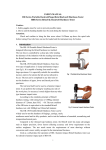
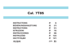
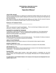
Hardness Image Measurement System
EIMS200 H V
User's Manual
I
Contents
1 Overview
1
1.1 Main Function
1
2.1 Specifications
2
4.2 Adjustment
7
5 Setup
5.1 Test Force
8
8
2 System Structure
3
5.2 Objective Magnification 8
3 Operation Interface
4
5.3 Statistic Points
8
3.1 Image Zone
5
5.4 Conversion
8
3.2 Information Zone
5
5.5 Tolerance
9
3.3 Setup Zone
6
6 Operation & Measurement
10
3.4 Data Zone
6
7 Calibration
11
3.5 Process Zone
6
7.1 Length Calibration
11
3.6 Operation Zone
6
7.2 Hardness Calibration
14
4 Installation & Adjustment
4.1 Installation
7
8 Trubleshoo
17
7
I
II
1 Overview
EIMS200HV is integrated image concept developed for a Vickers hardness measurement system. It
has the following mainly features:
1)The 200M pixels high resolution camera, direct display driver, no display distortion.
With simple structure, reliable operation, connect to ordinary monitor directly, no need computer can
realize Vickers hardness image measurement.
2)Mouse operation, very easy to use.
3)Digital image measurement, intuitive and accurate.
4)Creative embedded measurement software system, stable and reliable.
5)Easy for Installation, can replacement for optical micrometer simply.
1.1 Main Function
1)Test force setting:Test force setting covers all of the Vickers hardness test force.
2)Magnification settings: The most common use of the objective lens magnification can be set.
3)Conversion function: the measured Vickers hardness convert into other commonly used hardness
scale automatically, such as HRC, HRA, HRB, HB, etc.
1
4)Calibration function: Include length calibration and hardness calibration .
5)Statistics function: Can calculate mean and range, or set the tolerance for limit alarm display.
6)Brightness adjustment function: Adjust the display brightness according to different conditions of
the specimen surface, which will help to reduce measurement error and visual fatigue.
7)Image freeze functions: Eliminate measurement error caused by vibration or shock.
1.2 Specifications
1)Resolution: 0.1μm; Accuracy: 0.2μm;
2)Hardness resolution: 0.1HV;
3)Range of test force setting:120kg、100kg、50kg、30kg、20kg、10kg、5kg、3kg、2.5kg、2kg、
1kg、500g、300g、200g、100g、50g、25g、10g;
4)Magnification setting:40X、20X、10X、4X、2X、1X;
5) Signal output: D15 standard VGA connector;
6) Operation and control: PS / 2 mouse;
7) Lens Mount: C-mount;
8) Monitor: Display resolution 800 * 600 * 72Hz, 10 ", 15", 17 ", 19" and other common computer
monitors;
2
9) Power supply: 5VDC/1A;
10) Power consumption: about 2.5W;
11) Application environment: 0℃ ~ +50℃,
20% ~ 85%RH;
Storage environment: -20℃ ~ +70℃,
5% ~ 95%RH;
12) Dimensions: 80 * 80 * 55mm;
13) Weight: Approx. 210 g (Camera).
2 System Structure
System structure illustrated at right.
Camera of EIMS200HV is with a standard
C-mount, insert it into hardness tester.
Plug in the PS2 mouse, monitor cable ,power adapter and turn on.
Finally connect the camera power plug, and power it on.
3
3 Operation Interface
System interface
consists of image
Image
Zone
Measure
Lines
zone and
Information
Zone
Setup
Zone
operation menu
area, or can be
Data Zone
divided into six
regions.
Process
Zone
❶ Image Zone: In
Operation
Zone
this area, the
camera images is
collected and
4
Operation Interface
measured by measuring line;
❷ Information Zone: Showing the model and software version;
❸ Setup Zone: Set the test force, lens magnification, statistical points, tolerances, etc.;
❹ Data Zone: Displays the measured length and hardness values;
❺ Process Zone: Display statistic data and tolerance alarm, etc.;
❻ Operation Zone: There are some buttons for function operating.
3.1 Image Zone
Display images collected by camera from test surface. Four measurement lines are for the two
diagonal measurement of the indentation. Measuring line is
red, when selected with the mouse it becomes blue.
3.2 Information Zone
Show the information about system.
Information Zone
5
3.3 Setup Zone
In this zone, various measuring parameters can be set.
3.4 Data Zone
Horizontal
Indentation
diagonal
length
Setup Zone
Vertical
Data Zone
3.5 Process Zone
3.6 Operation Zone
Brightness
adjustment
Current
points
Mean
value
Rang
value
Conversion
Process Zone
Alarm
icon
Brightness: Adjust the brightness of Image Zone
for more clear.
Browse: Review the data measured.
Freeze: Take a snapshot of current image. Click it
Image
OK
Operation Zone
freeze
again will release freeze.
OK:
Click it to show a hardness value measured.
Or return to measurement in browsing and calibrating.
6
Browse
4 Installation & Adjustment
4.1 Installation
1) Turn the hardness tester power on.
Put a standard block on test table, turn the turret to objective position (if there are multiple objectives,
Please use the most common objective to align test surface).
Using the original optical micrometer to observe. Adjustment lifting mechanism until the image of test
blocks surface is clearest to observe.
Hold on this position, do not lift or move.
2) Mount the Interface tube on the camera.
3) Connect the power adapter plug, mouse with camera, and video cable connected to a monitor.
4) Insert the camera to the hardness tester camera port. If there is not a camera port, remove optical
micrometer directly.
Optical path conversion may be needed
4.2 Adjustment
1) Adjust the depth that the interface tube into till the image is most clear. If there is distance between
the camera tube and the tester interface, you should fill the gap with some washers to fix the tube.
2) If the brightness is not sufficient, adjust the illumination of the tester or brightness adjustment of
our system.
7
5 Setup
5.1 Test Force
Click on the right side of Test Force setting button
to cycle forward or backward test force
values.
5.2 Objective Magnification
Click
in right of the Objective box, can select the magnification of objective used. (1X, 2X, 4X,
10X, 20X and 40X)
5.3 Statistic Points
The calculation of mean value and range value is in a statistic group, in a group may contain the
number of points measured value , we called a statistical points
Click
in right of the Points box to plus or minus for setting it.
5.4 Conversion
Click
in right of the Scale box to change the hardness scale needed convert.(HRC,
HRB,HRA ,HR15N,HR15T,HR30N,HR30T,HR45N,HR45T)
8
5.5 Tolerance
You can set a hardness tolerance for the GO/NG test.
Upper limit input : Click upper limit box,
Click OK button
a keypad will pop up, Input the upper limit.
to confirm the input. You can enter the lower limit similarly.
9
6 Operation and Measurement
Freeze:
Focus the image to capture a indentation of hardness, rotate the camera slightly make the diagonal
of indentation in a horizontal or vertical position.Click on the "Freeze" button, put the current image
freeze, to get the best measurement state, click again is image unlocked.
Move the measuing lines:
On image display area, there are four lines, when the mouse is moved closer a line, it will be shifted
into the blue state, then the blue lines can drag with the mouse in effective display range.
You can drag these lines on 4 tip of indentation, then click "OK" button, the length of diagonal of
indentation are measured and Verckers hardness is obtained.
Torelence alarm:
If the measured hardness value exceeds the limits set, you will be prompted alarm, the "red
exclamation" flashes 5 times.
Printing:
You can print the data measued with a wireless printer. then each measurement time will print out the
current data, when statistica point is set , the average of the current and range can be printed out.
Brightness:
Six classes brightness can be set for each click.
10
7 Calibration
There are some differences in every hardness test system, such as the test force, the optical system.
It is necessary to do some calibrations in order to obtain reliable and accurate testing.
The measuring system provides two types of calibration methods, they are length calibration and
hardness calibration.
Length calibration is for calibrating the error of the hardness tester optical system. Hardness
calibration can calibrate integrated error of hardness test system.
In the first installation, recommended two types of calibration should be carried out. In daily use the
hardness calibration may be needed only.
7.1 Length Calibration
Length calibration is for correcting the error of the
optical system. Therefore, it is best for doing length
calibration when the optical system is changed. For
example:
1) Install the new measurement system.
2) Replace the lens.
3) Adjust or replace other parts of the optical system.
If the hardness is measured using a plurality of objective lenses, should be calibrated separately.
Length calibration can be done with a glass measuring scale ruler or a standard hardness block.
11
1) Procedure
The method is as follows:
① Measurement
Put a measuring ruler or a hardness block it has a standard indentation on the test table, adjust the
focus make the image most clear.
Move measuring line to the scale line on measuring ruler (or standard indentation diagonal), then
click OK button.
② Input the standard value
Move the mouse cursor to the Data zone that is between "D1" and "mm" or between "D2" and "mm",
press the left button of mouse for about 6 seconds, the keypad will pop up on the left bottom.
Through the keypad to enter the length of standard value (distance of ruler lines, or the theoretical
size of the standard indentation).
When finished, click the OK button
to confirm and exit the length calibration status.
D1 is horizontal, D2 is vertical. For more accurate measurements, D1 and D2 values in both
directions need to be calibrated.
③ Check
Measuring again as the steps in front, check whether correct. If the errors are still large or not
sufficient, should carry out the Length calibration once again.
12
2) Notes
① Use the scale ruler calibration, measure more lines (maximum length) as possible for the scale
error and visual errors minimized.
② Using standard hardness block, if diagonal of standard indentation is marked can be used it
directly.
If not, it is best to use the new hardness blocks, find a indentation by certification on test block.
Calculate diagonal length of indentation as standard values according to the hardness values and
test force. Formula for calculating is as follows:
D = 1.8544
F
H
D: Diagonal average length (mm), F:test force (kgf), H:hardness standard value (HV)
For example: Standard hardness block 420 HV5, so HV = 420HV、F = 5kgf .
D = 1.8544 ×
5
= 0.149(mm)
420
The standard lengths are available 0.149 for length calibration.
13
③ After each calibration, the calibration data is stored based on a objective len. If more than one
objective are used, need to be calibrated separately.
7.2 Hardness Calibration
Hardness Calibration can correct is integrated error of whole hardness test system.
Hardness Calibration typically requires in the course of regular or irregular manner, in order to
ensure the accuracy and reliability.
Hardness calibration cycle or frequency and associated conditions apply, please refer to the
operating instructions of hardness tester.
1) Steps
① hardness test
Do a hardness test, produce an indentation on the standard hardness block.
② Measure
Set the test force and the lens magnification correctly.
Measure the indentation diagonal in both directions.
the measurement is completed, press the OK button, the system calculates the corresponding
14
hardness value.
③ standard value of the input
Move the mouse cursor to "hardness" of the area of Data
Zone, click the left mouse button for about 6 seconds, the
keypad will pop up on the left bottom.
Through the keypad keys to enter the standard hardness
value.
When finished, press the OK button
to confirm and exit the hardness calibration status.
④ Check
If necessary, repeat steps ① ~ ③ calibrated check, you can also make another calibration.
2) Notes on hardness calibration
① The testing precision after calibration is related with whole testing system, if there is large error
still should check the other parts of test system such as test force, optical system or the test table.
② In the calibration test should be possible to take a standard test procedure (eg Test force
selection and test force dwell time settings).
15
③ Should select a hardness block close to common use to do the calibration.
④ The measuring system store the calibration data and processing is based on "objective
magnification + test force mix" corresponding.
Therefore, when a combination of "lens magnification + Test Force," have any change a new
calibration is needed.
Note: The system will call the most recent calibration method to calculate the hardness value.
Such as: your last calibration is length calibration, the system will use the length calibration data to
calculate the hardness values, and last calibrating is hardness calibration, the hardness is calculated
base on the hardness calibration.
16
8 Trubleshoot
No.
1
2
3
Phenomenon
Mouse cursor can not
be moved
Menu display bad
code
Inaccurate results
Possible reasons
plug the mouse after power on
No display
5
Image blurred
power on
Disturbed at power on
Power on again
calibration error
Recalibration
Monitor plug is loose?
4
Processing
Plug the mouse before
Whether the power supply?
Reconnect
focus no good, brightness is
Adjust the focus, or
not enough
adjust brightness
If other trouble occurs, please contact your dealer
17