1
CI/SfB
41
Rq2
IRISH AGRÉMENT BOARD
CERTIFICATE NO. 10/0352
Clean Energy Ireland,
Rathard, Aherla, Co. Cork.
T: 021 743 2829
M: 087 239 2024
W: www.CleanEnergyIreland.ie
Clean Energy Ireland Solar Heating Systems
Le système solaire de chauffage
Solarheizungssystem
NSAI Agrément (Irish Agrément Board) is designated by Government to issue European Technical Approvals.
NSAI Agrément Certificates establish proof that the certified products are ‘proper materials’ suitable for their intended
use under Irish site conditions, and in accordance with the Building Regulations 1997 to 2009.
PRODUCT DESCRIPTION:
This Certificate relates to the following Clean
Energy Ireland Solar Heating Systems:
•
Integra IDMK Flat Plate Integrated Collector
Each system is comprised of a solar collector,
sloping roof kit, hot water cylinder, anti-scald
valve, pump station, solar controller, expansion
vessel, hydraulic connections, solar discharge
vessel, antifreeze, user & installation manual and
labelling packs.
for slating and tiling, and prior versions of this
document or previous Irish codes of practice for
slating and tiling.
The Clean Energy Ireland Solar Heating Systems
should be installed by competent persons with
suitable training and practical experience of the
systems, and who have been approved by Clean
Energy Ireland and NSAI Agrément to install the
system.
This Certificate certifies compliance with the
requirements of the Building Regulations 1997 to
2009.
MARKETING, DESIGN AND MANUFACTURE:
The solar collectors are designed, manufactured
and tested by GREENoneTEC Solarindustrie
GmbH, Austria. The solar systems are designed,
assembled and distributed by:
USE:
The Clean Energy Ireland Solar Heating Systems
can be used in new and existing buildings with a
roof pitch of between 25o and 70o. The collector
must be fixed to a roof that meets the
requirements of I.S. ICP 2:2002 Code of practice
Clean Energy Ireland,
Rathard,
Aherla,
Co. Cork.
Readers are advised to check that this Certificate has not been withdrawn or superseded by a later issue by contacting
NSAI Agrément, NSAI, Santry, Dublin 9 or online at http://www.nsai.ie/modules/certificates/uploads/pdf/IAB100352.pdf
Part One /
Certification
1.1 ASSESSMENT
In the opinion of NSAI Agrément, the Clean
Energy Ireland Solar Heating Systems, if used in
accordance with this Certificate can meet the
requirements of the Building Regulations 1997 to
2009, as indicated in Section 1.2 of this Agrément
Certificate.
1.2 BUILDING REGULATIONS 1997 to 2009
REQUIREMENTS:
Part D – Materials and Workmanship
D3 – Proper Materials
The Clean Energy Ireland Solar Heating Systems,
as certified in this Certificate, are comprised of
‘proper materials’ fit for their intended use (see
Part 4 of this Certificate).
D1 – Materials & Workmanship
The Clean Energy Ireland Solar Heating Systems,
as certified in this Certificate, meet the
requirements for workmanship.
Part A - Structure
A1 – Loading
The Clean Energy Ireland Solar Heating Systems,
once appropriately designed and installed in
accordance with this Certificate, have adequate
strength and stability to meet the requirements of
this Regulation (see Part 3 of this Certificate).
Part B – Fire Safety
B4 – External Fire Spread
The Clean Energy Ireland Solar Heating Systems
will not affect the external fire rating of the roof
structure on which they are installed (see Part 4
of this Certificate).
Part C – Site Preparation and Resistance to
Moisture
C4 – Resistance to Weather and Ground
Moisture
The Clean Energy Ireland Solar Heating Systems,
once appropriately designed and installed in
accordance with this Certificate, will not affect a
roof’s resistance to the ingress of moisture (see
Part 4 of this Certificate).
Part L – Conservation of Fuel and Energy
L1 – Conservation of Fuel and Energy
The Clean Energy Ireland Solar Heating Systems
can be designed to meet the minimum level of
energy provision from renewable technologies
stated in this Regulation, i.e. 10kWh/m2/annum
contributing to energy use for domestic hot water
heating.
Certificate No. 10/0352 / Clean Energy Ireland Solar Heating Systems
1
Part Two /
Technical Specification and Control Data
2.1 PRODUCT DESCRIPTION
This Certificate relates to the following Clean
Energy Ireland Solar Heating Systems:
• Integra IDMK Flat Plate Integrated Collector
Each system is comprised of a solar collector,
sloping roof kit, hot water cylinder, anti-scald
valve, pump station, solar controller, expansion
vessel, hydraulic connections, solar discharge
vessel, antifreeze, user & installation manual and
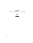
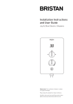
labelling packs. Figure 1 shows the main elements
of the flat plate solar heating system.
The Clean Energy Ireland Solar Heating Collectors
have been tested to EN 12975-2:2006 Thermal
solar systems and components – Solar collectors
– Test methods.
2.1.1 Integra IDMK Flat Plate Integrated
Collector
The Integra IDMK Flat Plate Integrated Collector
consists of a double header absorber construction.
The exposed panel components are resistant to
UV, moisture, freezing and salty environments.
The Integra range has two collector sizes: 2.5m2
or 1.25m2 gross areas. In these collectors, the
riser pipes are ultrasonically bonded to the
absorber plate. The risers are brazed to a
manifold on the top and the bottom. The
antifreeze enters and leaves the collectors via two
1” fittings located at the top of the housing. The
sensor is fitted into a pocket brazed directly to the
top
manifold
ensuring
accurate
collector
temperature readings. Any available energy
received onto the collector absorber surface heats
the pipe work behind the plate which then heats
the antifreeze within. The solar controller can
accurately read this temperature and switch on
the circulation pump accordingly. The antifreeze
solution travels down one side of the absorber and
up the other side, exiting to the next collector for
additional heating or to the cylinder for depositing
the heat.
Up to 6 collectors can be joined in series. They
have a maximum operating pressure of 10bar and
the mineral wool employed behind the absorber
assists in heat retention. The accompanying
flashing kit provides water and wind-tight
assembly.
2.2 MANUFACTURE
The Clean Energy Ireland Solar Heating Systems
are designed, manufactured and tested at the
GREENoneTEC ISO 9001 and ISO 14001
registered facility in Austria. GREENoneTEC
2
pressure test and inspect the absorber of every
panel.
2.3 DELIVERY, STORAGE AND HANDLING
Clean Energy Ireland supply a full package for
each solar heating system installation, which
includes (pre-assembled) solar collectors, sloping
roof kit, cylinder, anti-scald valve, pump station,
solar controller, expansion vessel, hydraulic
connections, stainless steel pipes to bring collector
hydraulics to attic space, solar discharge vessel,
antifreeze, user & installation manual and
labelling packs.
Collectors and cylinders should be transported
vertically. Heavy goods should not be loaded on
top of the kit boxes. Kits are available in 1st fit,
2nd fit or complete format. Care should be taken
when opening kits to prevent scratches or sudden
shocks to the collectors, and sharp objects shall
not be used to open the packaging.
2.4 INSTALLATION
2.4.1 General
The Clean Energy Ireland Solar Heating Systems
should be installed by competent persons with
suitable training and practical experience of the
systems, and who have been approved by Clean
Energy Ireland and NSAI Agrément to install the
system. The installer shall fully understand the
requirements of the customer, have completed a
user health & safety risk assessment and an
installation health & safety risk assessment.
A solar panel installation must be performed in
accordance with all Health & Safety legislation and
local building/planning regulations. The necessary
plumbing work should be undertaken by a
qualified, insured and solar-trained plumber. The
necessary electrical work should be undertaken by
a qualified electrical contractor.
The solar collectors are allowed be left exposed to
solar radiation before commissioning and when
the solar loop and manifold have been drained.
During commissioning (antifreeze filled), it is
advised not to have the panels exposed to the
sunlight for extended periods as the antifreeze will
degrade more quickly.
Fixings used with the Clean Energy Ireland Solar
Heating Systems must comply with Clause 4.11
and 5.9 of I.S. ICP 2:2002. All tiles adjacent to
the collectors should be mechanically fixed in
place. Flashings used with the systems must
comply with Clause 4.12 of I.S. ICP 2:2002.
Certificate No. 10/0352 / Clean Energy Ireland Solar Heating Systems
Figure 1: Main components of the Integra IDMK Flat Plate Collector System
Global solar radiation (W/m2)
400
700
1000
10
633
1176
1719
Tm - Ta1 (K)
30
433
976
1519
50
210
753
1296
1
Tm is the mean temperature of system fluid; Ta is the
ambient temperature
Performance (W)
Table 1: Power output per collector unit
Certificate No. 10/0352 / Clean Energy Ireland Solar Heating Systems
Dimensions
Gross Area
Aperture Area
Absorber Area
Height
Total Weight
Liquid Volume
Nominal Flow
Collector Connection
Absorber Type
Absorber Coating
Absorption
Emission
Covering
Heat Insulation
Collector Case
Efficiency η0 (aperture)
Heat Coefficient k1
Heat Coefficient k2
Max Stagnation Temperature
Max Operating Pressure
Hydraulic Connection
Integra IDMK 2.5
2063 x 1228 x 107 mm
2.53 m2
2.32 m2
2.29 m2
107 mm
54 kg
1.6 litres
120 l/hr
2 x 1” swivel nut
Harp absorber
Highly selective
95%
5%
Low iron, structured, solar safety glass
50mm mineral wool
Timber (sides & back)
78.10%
3.79 W/m2K
0.013 W/m2K
210oC
10 bar
Series connection
Integra IDMK 1.25
1015 x 1228 x 107 mm
1.25 m2
1.1 m2
1.08 m2
107 mm
27 kg
0.67 litres
80 l/hr
2 x 1” swivel nut
Harp absorber
Highly selective
95%
5%
Low iron, structured, solar safety glass
50mm mineral wool
Timber (sides & back)
78.10%
3.79 W/m2K
0.013 W/m2K
210oC
10 bar
Series connection
Table 2: Product Specifications
2.4.2 Pre-Installation
Sizing of the Solar Heating System
Minimising the risk of stagnation must be
considered by the installer when sizing a solar
heating system. The system must not be
oversized, but must comply with the requirements
of Part L of the Building Regulations 1997 to
2009. Clean Energy Ireland will use information
gathered on the Solar Quotation Enquiry Form to
design the system. The following steps should be
taken to correctly size a solar heating system:
•
Determine the daily hot water demand.
•
Calculate the hot water heat requirement.
•
Calculate the storage volume.
•
Size the required collector area.
•
Size the system components.
Sizing of Safety Equipment
Component sizes and output parameters are
relative to the output performance of the system
– the Clean Energy Ireland Technical Design
Guide should be consulted for each system.
Installation Health & Safety Risk Assessment
During the pre-installation site survey, a health &
safety risk assessment must be completed and
recorded by the installer on the Clean Energy
Ireland risk assessment form. Items assessed
include:
•
Access to roof (can scaffolding be erected).
•
Ability of roof structure to accommodate all
applied loadings.
•
Working at height.
•
Effects of wind and snow loads.
•
High temperature pipe work and liquids.
•
Antifreeze storage and discharge release.
•
Water quality.
•
Fire safety (installation of high temperature
components).
•
•
•
Risk of legionella.
Access for routing pipes.
Overhead wire protection.
Site Survey
Following
completion
of
the
initial
risk
assessment, contained within the Solar Quotation
Enquiry Form, a site survey must be carried out
by the installer using the Clean Energy Ireland
Pre-Installation Survey Form. This survey will
typically cover the following points:
•
Verify details from the Solar Quotation
Enquiry Form.
•
Identify any special user usage requirements.
•
Shading (current and potential risk).
•
Suitability of roof (is the roof finish in good
condition)
•
Roof orientation.
•
Access to collector location.
•
Pre-heat storage location (is there adequate
space for the cylinder and solar control
system)
•
Configuration of occupants DHW system and
anticipated usage patterns.
•
Sizing of the solar heating system.
•
Location of pump station assembly.
•
Control panel location and fixing height.
2.4.3 Roof Fixings
The collectors are mechanically fixed to the roof
trusses with aluminium L-brackets, 70mm coach
screws and stainless steel screws. Adverse bimetallic reactions are prevented with nylon
washers where required. The bracket system is
designed for up to and including 4-storey high
buildings and covers all Irish wind zones (as
illustrated in Figure NA.1 in Irish National Annex
to Eurocode 1). It is recommended that a
structural engineer is used to advise on the
Certificate No. 10/0352 / Clean Energy Ireland Solar Heating Systems
strength of the roof structure and its ability to
accommodate all the applied loadings.
The collector’s location should be measured and
special concern given to the final positioning of
the flashing periphery. Four bracket sets per
collector are required, two at the top and two at
the bottom. These should be directly fixed into the
rafters (preferred) or to additional, structurally
designed and adequately supported timber
bearers (not standard roof battens). The coach
screw locations are pre-drilled with a 5mm drill bit
to prevent damaging the structure of the truss
when installing the coach screw. The installer shall
ensure the coach screws are centred on the
available truss and applied perpendicular to the
truss top surface.
When installed in accordance with the Certificate
holder’s instructions, this system creates a
permanent seal which ensures the water tightness
and wind tightness of the external building
envelope is maintained. Where pipes penetrate
the interior of the attic space, e.g. through the
roof underlay, insulation or plasterboard, they
must be made airtight through use of suitable
airtight tapes, seals of grommets, and additional
grommets can be supplied by the Certificate
holder for this purpose. Where existing insulation
and/or plasterboard is displaced, it must be
replaced with similar material and made airtight.
The collectors are mounted onto treated timber
bearers, designed and specified for roof
installation, to provide support underneath the
collector. The stainless steel screws (with fitted
nylon washers) are drilled into the collector’s
timber frame.
Figure 4: Felt grommet where pipework
penetrates felt
Figure 2: Fixing bracket on lower side ready
to take collector
2.4.5 Flashing Kit Installation
Clean Energy Ireland supplies four separate
flashing kits for the following roof finish types:
•
Irish Slate (Anthracite)
•
Flat Tile (Anthracite)
•
Curved Tile with Lead Skirting (Anthracite)
•
Irregular Tile with Lead Skirting (Dark Brown)
They are manufactured in Austria and comply with
Section 4 of I.S. ICP 2:2002 and have been
assessed as being appropriate for use with the
Integra IDMK Collector. Stainless steel plumb
screws for fixing the flashings to the frame of the
collector are supplied with the flashing kit. No
additional lead, sealants or fixings are required.
Tile
Fillet
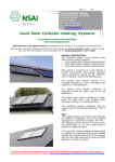
Figure 3: Collectors fixed on roof before
installation of flashings
2.4.4 Roof Penetrations
The Certificate holder supplies a felt grommet for
carrying the insulated solar pipes and collector
sensor through the roof felt into the attic space.
This grommet is manufactured from EPDM
(Ethylene Propylene Diene Monomer) and is used
to ensure water will not breach the felt.
Figure 5: Side flashing for tiled roof
Certificate No. 10/0352 / Clean Energy Ireland Solar Heating Systems
It is essential that the collector temperature
sensor is located in the flow of the collector, as
shown in Figure 1.
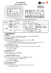
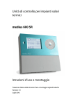
Figure 6: Finished flashing kit on slate roof
The installer shall start applying the flashings at
the base of the collector. The side and centre
flashings are then fitted, followed by the top
tapering flashing. The supplied plumb screws
must be used to prevent moisture entering
through the flashing. Soakers shall be applied if
slate is the roof finish; alternatively a solid
flashing side piece is used incorporating a double
channel for capturing the flowing rain and utilizing
a foam fillet as shown in Figure 5.
2.4.6 Connections
In any solar heating system, the ‘return’ refers to
the intake in the collector where liquid is returning
to be reheated. The ‘flow’ refers to the collector
side where the liquid is flowing to the heat
exchanger.
All copper pipework should meet the requirements
of I.S. EN1057:2006+A1:2010:
Copper and
copper alloys – Seamless round copper tubes for
water and gas in sanitary and heating applications
and be clearly marked in accordance with BS
1710:1984 Identification of pipelines and services.
Ideally, pipes should take the shortest route to
the solar store and always slope back to the pump
station. In order to reduce heat losses, antithermal siphoning measures should be taken in
the pipework between cylinder and pump.
The PT1000 collector sensor shall be inserted into
the sensor pocket next to the flow pipe. The
sensor must be mechanically fixed with a metal
pipe clip to ensure the sensor won’t inadvertently
get displaced from the sensor pocket. The gaskets
employed in the fittings are made from graphite
which has an operating temperature range -100oC
to +500oC, and is compatible with a wide range of
chemicals including the supplied antifreeze. The
brass fittings comply with IS EN 12164:2000
Copper and copper alloys – Rod for free
machining purposes, and the solar pipe is
manufactured from AISI 316L stainless steel and
has an operating temperature range of -270oC to
+600oC.
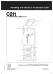
Top flashing
Soakers (Slate only)
2.8m
high
2.5m² gross
area panel
dimensions
shown
Solar
panel
Soakers for
slate flashings
Bottom Flashing
Two panels = 2.8m, including flashing
(+ 1.23m for each additional panel)
Figure 7: Plan of flashings for 2-panel Integra IDMK Collectors on slated roof
Certificate No. 10/0352 / Clean Energy Ireland Solar Heating Systems
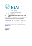
Figure 8: Completed installation on slate roof
Flexible Pipe Connections
Flexible pipe connections are required to connect
the collectors through the building fabric and
allow flexibility in connecting to the internal pipe
work. Flexible stainless steel pipes are available in
both ¾” and 1” diameter. If connecting one
diameter pipe to another, a suitable reducer
compression fitting is required to make the
connection.
Types of Connections
The only pipes which should be used with a solar
installation are copper
pipe
(to
IS
EN
1057:2006+A1:2020),
continuous
flexible
stainless steel or mild steel (to ISO 9329-1:1989
Seamless steel tubes for pressure purposes –
Technical delivery conditions – Unalloyed steels
with specified room temperature properties).
When using copper pipe, only compression or
brazed joints can be used. Solder and galvanised
fittings will not withstand high temperature or
expansion and are therefore not suitable for solar
pipe work.
HT/Armaflex. This is essential as regular pipe
insulation
will
degrade
at
temperatures
experienced by solar pipes. The insulation applied
must conform to Part L of the Building Regulations
1997 to 2009. When the insulated solar pipes are
outside the heated building envelope, the wall
thickness of the insulation should be at least equal
to the diameter of the pipe. The only pipes which
should not be insulated are the pipes to the safety
vessel as they should allow heat to dissipate when
the system is experiencing excessive heat and
pressure.
2.4.7 Cylinder
Consideration should be given to the load bearing
requirements of the cylinder and the space
required to house the cylinder, pump station,
expansion vessel, valves and pipework with
regard
to
installation,
inspection
and
maintenance.
Note: PEX/Plastic/PEX-ALU-PEX or galvanised
tubing or fittings should NOT be used under any
circumstances.
The Certificate holder supplies the Telford Solar
Cylinder, the Kingspan Albion Ultrasteel Solar
Cylinder and the Kingspan Coppercraft ECO
Cylinder. In addition, other DHW cylinders may be
used, provided they have NSAI Agrément
certification for use with this system.
Insulation
All pipe work on the solar loop shall be insulated
with high temperature insulation suitable for use
at
temperatures
above
150oC,
such
as
The Telford Cylinder is a Duplex stainless steel
with one, two or three coils, and is available for
pressurised systems and open vented systems.
The Kingspan Albion Ultrasteel Cylinder is a
Certificate No. 10/0352 / Clean Energy Ireland Solar Heating Systems
duplex two coil stainless steel cylinder, and is
used for pressurised systems. The Kingspan
Coppercraft ECO Cylinder is a two coil copper
cylinder and is used for open vented systems
only.
A twin coil hot water storage cylinder enables
energy input from the central heating system to
the top half of the tank, and energy input from
the solar heating system to the bottom half of the
tank. Cylinder storage size is calculated at
approximately 130% of the household’s hot water
demand,
which
is
estimated
at
50-60
litres/adult/day.
The
Certificate
holder
recommends a 200 litre cylinder for a two to three
adult household, and a 300 litre cylinder for a four
to five adult household.
2.4.8 Solar Pump Station
Both single string and dual string WATT pump
stations are available for use with the Clean
Energy Ireland Solar Heating Systems. A dual
string pump station has an air vent that allows
bleeding of air during the filling process. Each
WATT pump station is available in two flow rates:
2-12 litres and 8-28 litres. The Tiemme 4745
pump station can also be used with the Clean
Energy Ireland Solar Heating Systems. This pump
station is available in three flow rates: 1.5-6
litres, 4-16 litres and 8-28 litres. The flow rate
required on a system is typically 1 litre/minute
per square metre installed. Therefore, a 2-12 litre
pump station will be sufficient for systems up to
12m2.
Connections of flow and return pipe work to the
pump station are made with ¾” flat seal male
threads. Each pump station has an expansion
vessel hose and bracket for rapid mounting of the
vessel. There is a vessel isolating valve fitted as
standard on the bracket to allow removal of the
vessel prior to pressure testing the system
hydraulics.
The pump station and vessel must be fixed to a
sound surface suitable for holding the weight of
the unit, and should be in an accessible location
and not obstructed or concealed.
Figure 10: Tiemme 4745 pump station
2.4.9 Safety Vessel Connections
The Pressure Relief Valve (PRV) is rated at 6bar,
and conforms to EN 4757-1 and Directive PED
97/23/CEE, and is certified to TÜV Solar. The PRV
may discharge heat transfer fluid which must be
channelled
into
a
container
capable
of
withstanding high temperature discharge and
containing 1.5 times the total collector volume.
The container should be secured so it cannot be
removed or spilled and have a drain facility. The
PRV must not be channelled into a drain or any
pipe work which will allow it to enter the normal
water course.
2.4.10 Solar Expansion Vessel
The Zilmet solar expansion vessel supplied with
the Clean Energy Ireland Solar Heating Systems
complies with DIN 4757 and is available in
incremental sizes between 12 litres and 105 litres.
The vessel is pre-charged to 2.5bar and has a
maximum working pressure of 10bar. While the
vessel membrane can tolerate temperatures of
100oC, it is recommended to fit the vessel on the
return string of the pump station (cooler side).
2.4.11 Solar Discharge Vessel
The Solar Discharge Vessel (SDV) is supplied with
a mounting bracket and screws, and comes with
the necessary hose length and hose fittings to be
applied to the PRV. The SDV comes in three sizes:
5 litres, 12 litres and 18 litres. A brass drain is
fitted to the base of the SDV. Un-insulated copper
or stainless steel pipe shall be used between the
pump station and discharge vessel.
Figure 9: WATT Dual String pump station
with air vent
Figure 11: Solar Discharge Vessel
Certificate No. 10/0352 / Clean Energy Ireland Solar Heating Systems
2.4.12 Solar Differential Controller
Clean Energy Ireland supplies two types of solar
controller: Resol Deltasol BS Plus and Prozeda
Solar Reg II Basic Controller. The Resol Deltasol
BS Plus accepts 4 x PT1000 inputs and provides 2
x output relays. The functions in this controller
allow auxiliary heating functions which could be
used where there is a risk of legionella. It also
controls East-West collector configurations and
facilitates priority heating of cylinder zones and
two storage cylinder set-ups.
Wiring the Solar Controller
All electrical aspects of the installation should be
undertaken in accordance with ETCI regulations
by a qualified electrician. For safety, the pump
and sensor connections should always be wired
prior to connecting power to the solar control
panel. The solar control panel must have a
permanent electrical power supply which must not
be interrupted by a time switch. A switchable
fused spur with LED should be used for the
system. The solar heating system does not have
to be drained if the power is disconnected.
However, if the system is unused for extended
periods it is recommended to drain the system to
prevent degradation of the anti-freeze.
The solar control panel should be located in a
prominent location that is readily accessible and
frequently occupied, normally on the landing
outside the solar store, fixed not less than 1.5m
above floor level. The control panel display should
be readily visible at all times with clear access and
not concealed or obstructed. In order to protect
the normal operation of the control panel, it
should be located at least 100mm from insulated
pipes which may become hot during operation.
Clean Energy Ireland can supply a lightning
protection kit To limit potential damage to the
systems from lightning. See Section 3.6 of this
Certificate.
Figure 12: Resol & Prozeda control panels
2.5 COMMISSIONING
Commissioning must be carried out by a Clean
Energy Ireland trained and approved installer of
the system. The system should not be
commissioned if the collectors are in excess of
70oC because the pressures recorded will not be
stable in the long term.
Expansion Vessel
Prior to filling the system, the expansion vessel
pressure must be set 0.3bar below the system
pressure.
The pressure is checked at the base of the
expansion vessel and the bleed valve may be bled
or topped up with a pump. Omitting to perform
this check will result in irregular pressure readings
during the commissioning and normal use of the
system.
Filling the Loop
It is important that a motorised flush and fill
centre is used to fill and pressurise the system
with the antifreeze as per the commissioning
instructions in the installation manual.
1.
Remove the expansion vessel at the vessel
isolation valve.
2.
Check all joints are closed tightly.
3.
Connect the pump station filling valve closest
to the manometer to the filling station flow
(from pump).
4.
Close the flow meter by turning the flow
control screw to horizontal position.
5.
Connect the valve closest to the flow meter
to the filling station return (hose back to
reservoir).
6.
Check that flush and fill valves are open
while the cylinder and SDV drain valves are
closed.
7.
Fill the filling pump reservoir with the
supplied antifreeze, open the filling pump
supply and switch on.
8.
Allow the jet pump to run for approximately
10 minutes. If fitted, manual air vents
should be cleared at intervals during this
time.
9.
Open the solar pump vent screw with a large
screwdriver to release any trapped air.
10. Increase pressure in the system to 4bar and
close all valves.
11. Check all joints for leaks, allow system to
settle for 30 minutes.
12. Test pressure release valve by turning once.
13. When satisfied all pipe work is tight, release
pressure back into filling station.
14. Fit the expansion vessel and measure the
pressure within, which should read 2.5bar.
15. Repeat steps 4 to 9.
16. Set pressure to 3bar.
17. Manually turn on solar pump and bleed any
remaining air through air vents.
18. Adjust the system pressure to a final value
of 2.7bar by releasing liquid from the filling
point.
19. Adjust flow rate as follows: 2 panels = 4
litres/minute; 3 panels = 6 litres/minute.
Certificate No. 10/0352 / Clean Energy Ireland Solar Heating Systems
20.
Manually turn on solar pump and allow it to
run for a minimum of 30 minutes, bleeding
any remaining air.
Setting the Flow Rate
The pump may only be run when the system has
been filled as dry operation will damage the
pump.
The
desired
flow
rate
is
1
litre/minute/panel m2 (1 panel = 2.32m2).
•
Set the pump to the first speed and run it
manually from the controller.
•
If the desired flow rate is exceeded, set the
flow meter to the desired rate by adjusting
the flow meter valve with the pump running.
•
Otherwise repeat this step at the next pump
speed and continue until the desired flow rate
is achieved.
•
Stop the pump.
•
Set the solar controller to “Automatic”.
Final Commissioning Requirements
•
The installer must complete two copies of the
Commissioning Certificate. One copy is left
with the customer in the User Manual and the
second copy is kept by the installer.
•
The installer must complete the Maintenance
Log, and apply it in a viewable position, for
example on the expansion vessel or the
cylinder.
•
The installer must apply the Product ID label
to the controller and the HOT PIPE warning
labels (x2) to the cylinder flow and return.
•
The installer shall hand over the User Manual
to owners, and instruct users on all aspects of
the documentation and how to effectively use
the solar equipment.
User Manual
After commissioning, a user manual is given to
the
homeowner
which
contains
important
information about the system. The user manual
includes a recommended maintenance schedule,
commissioning certificate, full contact details of
the installer and guidance on use.
Decommissioning the System
Due to temperatures potentially exceeding 170oC
and pressures up to 6bar, a solar installation
should only be decommissioned by a trained
individual. The system should be decommissioned
in low light, ideally in the morning when the solar
loop should be coolest.
2.6 RETROFITTING/REPLACING
The IDMK collectors are easily retrofitted to
existing roofs. During the pre-installation survey,
special attention must be given to the condition of
the existing roof structure and its ability to take
the additional applied loadings of the collector as
described in the Clean Energy Ireland Structural
Verification Procedure.
The required slates/tiles are removed. The panels
are fixed as described in Section 2.4. The
slates/tiles are then integrated into the correct
flashing assembly.
Should the collectors require replacing then the
flashings are removed in reverse order to the
installation, collectors replaced and the flashing
reinstated.
Figure 13: Panels being retrofitted to tiled roof
Certificate No. 10/0352 / Clean Energy Ireland Solar Heating Systems
Part Three /
Design Data
3.1 STRENGTH AND STABILITY
When tested in accordance with EN 129752:2006, the Integra IDMK Collector was tested to
3000 Pa positive pressure (i.e. downward
pressure) without failure occurring. Using the
safety factor of 1.5 for positive pressure (Section
5.9.1 of EN 12975-2:2006), the Clean Energy
Ireland Solar Heating Systems can withstand a
positive pressure of up to 2000 Pa. The Integra
IDMK Collector was also tested to 2000 Pa
negative pressure (i.e. upward pressure/uplift)
without failure occurring. Using the safety factor
of 2.0 for negative pressure (Section 5.9.2 of EN
12975-2:2006), the Clean Energy Ireland Solar
Heating Systems can withstand a negative
pressure of 1000 Pa.
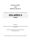
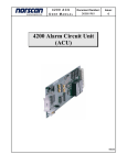
The Clean Energy Ireland Solar Heating Systems
and fixing system are designed to cover dwellings
up to 4 storeys in height in all zones shown in
Figure 14. For buildings greater than 4 storeys,
and for sites with altitudes greater than 130m in
Zone IV, 160m in Zone III and 275m in Zone II,
Clean Energy Ireland’s structural engineer will
calculate the site specific wind loads in
accordance with I.S. EN 1991-1-4 Eurocode 1 –
Actions on structures – General actions – Wind
actions to verify that the wind loads are
acceptable for the collector and fixing system.
3
To minimise the effect of wind load on the
collectors, it is recommended that collectors are
not installed within 0.5m of the ridge or eaves.
The host roof structure, and any modifications
necessary to accommodate the Clean Energy
Ireland Solar Heating Systems, should be
checked by a suitably qualified engineer in
accordance with the Building Regulations 1997 to
2009. The installer of the system must ensure
that this has been done prior to commencing
installation, as per the Clean Energy Ireland
Structural Verification Procedure.
3.2 IMPACT RESISTANCE
The Integra IDMK Collector was tested for impact
resistance in accordance with EN 12975-2:2006,
and met the pass criteria for impact resistance.
3.3 COLLECTOR EFFICIENCIES
The ability to convert solar energy into thermal
energy is expressed by the optical efficiency, η0,
(zero-loss collector efficiency in SEAI DEAP
software) of the system. The heat loss coefficient
value, a0, is also used in the DEAP software.
Table 3 shows the η0 and a0 values for the Clean
Energy Ireland Solar Heating Systems obtained
when tested to EN 12975-2:2006.
Figure 14: Basic Wind Velocity (ref. Irish National Annex to Eurocode 1)
Certificate No. 10/0352 / Clean Energy Ireland Solar Heating Systems
At high levels of sunlight (1000 W/m2), when the
average system fluid temperature is slightly
higher than ambient temperature (10K), for a
solar heating system utilising the Clean Energy
Ireland Solar Collector, each collector can
transfer approximately 1.719 kW of energy to the
building hot water store.
Test results of the performance of the collectors
are shown in Tables 1 and 2.
Model
IDMK 25
IDMK 15
Aperture area
2.32 m2
1.1 m2
η0
0.781
0.781
a0
3.796
3.796
Table 3: Zero-Loss Collector Efficiency and
Heat Loss Coefficient Values
3.4 RISK
OF
BACTERIAL
GROWTH
/
LEGIONELLA
The installer of the Clean Energy Ireland Solar
Heating System completes a Legionnaires
Checklist as part of the initial risk assessment of
the site during the pre-installation survey. If a
risk of legionella is identified during this risk
assessment a solar control panel with legionella
controls must be installed (Deltasol BS Pro).
Examples of areas where a risk of legionella may
be identified include long periods of non-use of
the hot water supply, infrequently used outlets
such as showers and taps, and residents who are
highly vulnerable to infection. In addition, a
thorough review of all pipework is required in
such situations with alterations incorporated as
required to limit risks. Unused ‘dead legs’ shall be
removed and recirculation pipework heavily
insulated. Recirculation circuits should be timed
on/off for no more than 8 hours per 24 hour
period (for conservation of energy).
Information and guidance is provided to the
homeowner by the installer on the correct
operation of the solar heating system during
normal operation and after periods of non-use, to
help reduce the risk of legionella. For further
guidance, refer to the HPSC (Health Protection
Surveillance
Centre)
document
National
Guidelines for the Control of Legionellosis in
Ireland and the NDSC (National Disease
Surveillance Centre) document The Management
of Legionnaires’ Disease in Ireland.
The Clean Energy Ireland Deltasol BS Pro
controller has an auxiliary heat activation
function which enables a boiler to heat the
cylinder to a set temperature and at a frequency
set by a timer.
A thermostatic mixing valve should be installed
to the hot water exiting the solar cylinder to
prevent accidental scalding due to high
temperatures. Clean Energy Ireland recommends
and supplies the Tacanova MT52 mixing valve.
Care should be taken to prevent any debris from
entering the mixing valve and in open-vented
systems the mixing valve shall not interfere with
cylinder venting.
The Clean Energy Ireland control panel uses the
following functions on the Deltasol BS Pro
controller to prevent collector and cylinder
overheating from occurring.
Anti-Stagnation
If the adjusted maximum store temperature is
reached, the solar pump remains activated in
order to avoid overheating of the collector. The
temperature of the cylinder may continue to
increase but only up to 95oC (emergency
shutdown of the store). In the evening the solar
heating system continues running until the
cylinder is cooled down to the adjusted maximum
store temperature via collector and pipes. This
function is not suitable where tube collectors are
used due to the tube high heat retention
properties.
Figure 15: Auxiliary Heating Diagram
Heat Dumping
This function is typically enabled to send
unwanted cylinder heat to a heat dump, such as
a radiator. The heat dump function has a switchon temperature differential and a switch-off
temperature differential enabling the user to
send even low temperature levels to a radiator
during, for example, holiday periods or in a
vacant holiday home.
3.5 HIGH TEMPERATURE CONDITIONS
Continuous temperatures in excess of 170oC will
cause a degrading of the antifreeze solution and
its inhibiting properties and may also cause
damage to the collectors, pump station and
expansion vessel in the system.
Certificate No. 10/0352 / Clean Energy Ireland Solar Heating Systems
Figure 16: Heat Dumping Diagram
3.6 LIGHTNING PROTECTION
To limit potential damage to the systems from
lightning, a lightning protection diode should be
incorporated into the system. Clean Energy
Ireland can supply a lightning protection kit for
this purpose. The solar flow and return pipe work
must be bonded as per the ETCI requirements to
avoid electric potential differences.
In general, the risk of property damage due to
lightning is relatively low in Ireland for domestic
properties, and installation of Clean Energy
Ireland Solar Heating Systems does not generally
increase the level of risk as the collectors are
placed below ridge level and not higher than the
chimney. Where a building requires specific
lightning protection, the collector should be
connected to the lightning protection system.
Certificate No. 10/0352 / Clean Energy Ireland Solar Heating Systems
Part Four /
Technical Investigations
4.1
BEHAVIOUR IN RELATION TO FIRE
The roof covering on which the collectors are
installed must have an AA, AB or AC rating as
stated in Table 4.4 of TGD to Part B of the
Building Regulations 1997 to 2009.
When tested in accordance with BS 476-3:2004
Fire tests on building materials and structures –
Classification and method of test for external fire
exposure to roofs, the Integra IDMK Flat Plate
Integrated Collector achieved an EXT.S.AA rating.
The Integra IDMK Flat Plate Integrated Collector
also achieved a BRoof(T4) classification per IS EN
13501-5:2005, when evaluated against ENV
1187-4:2005 Test methods for external fire
exposure to roofs.
Where pipes pass through fire-rated walls or
cavity barriers, they must be adequately fire
stopped, without compromising provision for
thermal expansion.
Combustible materials should not be exposed to
solar heating equipment having operating
temperatures which can cause ignition.
4.2 WEATHERTIGHTNESS
The Clean Energy Ireland Solar Heating Systems
when installed in completed roofs will provide
adequate resistance to weather ingress, when
installed in accordance with the Certificate
holder’s instructions. Particular attention must be
paid to correct installation of the flashing
components the grommets and areas where pipe
work enters the building.
4.3 MAINTENANCE
Users should regularly check the temperatures
which the solar control panel is recording. If the
collector temperatures have been excessively
high, i.e. over 170oC, it is recommended that the
antifreeze level be checked using a refractometer
by an approved installer/qualified engineer. If the
antifreeze has lost its antifreeze properties, the
system should be refilled with fresh antifreeze
fluid.
4
4.4 DURABILITY
In the opinion of NSAI Agrément, when installed
in accordance with this Certificate and the
manufacturer’s
instructions,
and
the
recommended maintenance programme, the
Clean Energy Ireland Solar Heating Systems will
have a design life as solar collectors in the order
of 20 years with regular inspection and
maintenance.
The structural durability of the fixings, flashing
etc. if maintained as per the Clean Energy
Ireland
maintenance
schedule,
has
been
assessed and will have a design life equivalent to
that of the roof structure in which it is
incorporated.
4.5 TESTS
AND
ASSESSMENTS
WERE
CARRIED
OUT
TO
DETERMINE
THE
FOLLOWING
• Fire resistance
• Internal pressure of absorber
• High temperature resistance
• Exposure
• Determination of stagnation temperature
• External and internal thermal shock
• Rain penetration
• Mechanical load
• Impact resistance
• Thermal performance
4.6 OTHER INVESTIGATIONS
(i) Existing data on product properties in relation
to fire, toxicity, environmental impact and
the effect on mechanical strength/stability
and durability were assessed.
(ii) The manufacturing process was examined
including the methods adopted for quality
control, and details were obtained of the
quality and composition of the materials
used.
(iii) Site visits were conducted to assess the
practicability of installation and the history of
performance in use of the product.
It is recommended that the solar heating system
is serviced annually by a qualified engineer and
immediately if the system shows evidence of
having lost pressure or has discharged liquid at
the pressure relief valve. Items checked on the
annual service include the system pressure, flow
rate, antifreeze level, pH reading, inspection of
the collectors and inspection of the collectors and
flashing components.
Certificate No. 10/0352 / Clean Energy Ireland Solar Heating Systems
Part Five /
Conditions of Certification
5.1 National Standards Authority of Ireland
("NSAI") following consultation with NSAI
Agrément has assessed the performance and
method of installation of the product/process and
the quality of the materials used in its
manufacture and certifies the product/process to
be fit for the use for which it is certified provided
that it is manufactured, installed, used and
maintained in accordance with the descriptions
and specifications set out in this Certificate and in
accordance with the manufacturer's instructions
and usual trade practice. This Certificate shall
remain valid for five years from date of issue so
long as:
(a) the specification of the product is unchanged.
(b) the Building Regulations 1997 to 2007 and
any other regulation or standard applicable to
the product/process, its use or installation
remains unchanged.
(c) the product continues to be assessed for the
quality of its manufacture and marking by
NSAI.
(d) no new information becomes available which
in the opinion of the NSAI, would preclude
the granting of the Certificate.
(e) the product or process continues to be
manufactured, installed, used and maintained
in
accordance
with
the
description,
specifications and safety recommendations
set out in this certificate.
(f) the registration and/or surveillance fees due
to IAB are paid.
5
(c) whether individual products have been
manufactured or installed by the Certificate
holder in accordance with the descriptions
and specifications set out in this Certificate.
5.4 This
Certificate
does
not
comprise
installation instructions and does not replace the
manufacturer's directions or any professional or
trade advice relating to use and installation which
may be appropriate.
5.5 Any recommendations contained in this
Certificate relating to the safe use of the certified
product/process are preconditions to the validity
of the Certificate. However the NSAI does not
certify that the manufacture or installation of the
certified product or process in accordance with
the descriptions and specifications set out in this
Certificate will satisfy the requirements of the
Safety, Health and Welfare at Work Act 2005, or
of any other current or future common law duty
of care owed by the manufacturer or by the
Certificate holder.
5.6 The NSAI is not responsible to any person
or body for loss or damage including personal
injury arising as a direct or indirect result of the
use of this product or process.
5.7 Where reference is made in this Certificate
to any Act of the Oireachtas, Regulation made
thereunder, Statutory Instrument, Code of
Practice, National Standards, manufacturer's
instructions, or similar publication, it shall be
construed as reference to such publication in the
form in which it is in force at the date of this
Certification.
5.2 The NSAI Agrément mark and certification
number may only be used on or in relation to
product/processes in respect of which a valid
Certificate exists. If the Certificate becomes
invalid the Certificate holder must not use the
NSAI Agrément mark and certification number
and must remove them from the products
already marked.
5.3 In granting Certification, the NSAI makes no
representation as to;
(a) the absence or presence of patent rights
subsisting in the product/process; or
(b) the legal right of the Certificate holder to
market,
install
or
maintain
the
product/process; or
Certificate No. 10/0352 / Clean Energy Ireland Solar Heating Systems
NSAI Agrément
This Certificate No. 10/0352 is accordingly granted by the NSAI to Clean Energy Ireland on
behalf of NSAI Agrément.
Date of Issue: October 2010
Signed
Seán Balfe
Director of NSAI Agrément
Readers may check that the status of this Certificate has not changed by contacting NSAI
Agrément , NSAI, 1 Swift Square, Northwood, Santry, Dublin 9, Ireland. Telephone: (01) 807
3800. Fax: (01) 807 3842. www.nsai.ie
Certificate No. 10/0352 / Clean Energy Ireland Solar Heating Systems