1
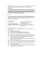
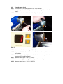
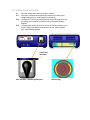
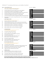
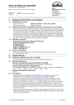
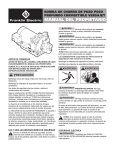
VERSAJET console performance
and safety check
1.0 Purpose
The purpose of this procedure is to provide a performance and safety check for the
VERSAJET™ power console, model 50700 (120V) and model 50750 (240V).
Important note
The VERSAJET console is NOT user serviceable and under no situation should
the casing be opened. Any attempt to open the unit by the user will void all
warranties and render the user responsible for all subsequent repairs to the
unit. Contact your local Smith & Nephew customer care representative or sales
representative to resolve all console problems.
2.0 Scope
This procedure is applicable to all VERSAJET consoles as a reference guide to help
customers wishing to perform performance checks by themselves. Refer to the
Versajet Hydrosurgery system manual for additional information on the correct use of
the console and its specifications.
3.0 Equipment
Optical Tachometer
Ametek 1726 or equivalent (hospital is
responsible for purchase)
Electrical testing equipment
(hospital responsible for purchase)
RPM verification tool (speed stick) Smith & Nephew (contact your local sales
representative)
4.0 Performance check procedure
A checklist is provided at the end of this document to record the results of the
following checks.
4.1
4.1.1
4.1.2
4.1.3
4.1.4
4.1.5
4.1.6
4.1.7
4.1.8
4.1.9
Physical appearance check
Make sure console is unplugged from electrical power.
Check console for visible dents, cracks or missing pieces.
Check that fan slots are free from obstructions, dust or foreign materials.
Inspect console ventilation slots located on rear and back of the instrument.
Remove obstructions, dust or foreign materials using vacuum and or
household all purpose cleaner and wipes.
Check that the black console lever on the UI (User Interface) rotates freely
between 4 and 6 o’clock position.
Check that on/off rocker switch moves to each position and remains in place.
Check foot switch and attached cord for signs of loose or missing insulation.
Check foot switch mechanical operation for engage and disengage by
depressing and releasing.
Inspect power cord for any frayed or missing insulation, and bent, loose or
missing plug blades or earth/ground.
4.2
4.2.1
4.2.2
4.2.3
4.2.4
4.2.5
•
•
4.2.6
•
•
System diagnostics check
Make sure console is plugged into an electrical outlet.
Turn the main power switch to the “on” position and verify that the switch is
illuminated and green in color (verify the lamp extinguishes with the switch in
the “off” position).
Verify console defaults to power level “1” when unit is turned on using front
power switch.
Verify the unit power level value changes when arrows are depressed – there
are a total of ten different power settings.
Verify that the “door” error lamp is:
Illuminated when the lever is open (4 o’clock)
Off when user interface knob is in the closed position (6 o’clock)
Verify the “pedal” error lamp is:
Illuminated when the footswitch connector is not plugged into the front of the
console.
Off when footswitch connector is inserted.
Note: lamp “on” signals a system error that will prevent the console from
operating
Console control / display panel
Error lamp
indicators
Main power
switch
Power level
switches
Footswitch
connection
4.3
4.3.1
4.3.2
4.3.3
Console speed check
Turn the knob on the user interface to the “open” position.
Insert the “speed stick” until fully seated into the opening in the user interface
(step 1).
Turn the user interface knob to the “closed” position (step 2).
Step 1
Step 2
Step 3
Step 4
4.3.4
4.3.5
4.3.6
4.3.7
4.3.8
4.3.9
Set the console to lowest setting of 1 (Step 3).
Depress and hold the footswitch down to allow the console to cycle its motor/
transmission.
Aim the tachometer “optical beam” so that the reflector on the speed stick
produces a RPM reading (Step 4).
Measure speed (Spec = 390 +/- 50 RPM).
Set console to highest setting of 10 and repeat the measuring steps.
Measure speed (spec = 1210 +/- 100 RPM).
5.0 Safety check procedure
5.1
5.1.1
5.1.2
5.1.3
Electrical testing check (also see product manual)
Ensure the console and test equipment are set to the same input
voltage setting prior to conducting electrical testing.
Connection to “mains” grounding is accomplished through use of the
grounding post located on the back of the console (see following
diagram)
The steel plate behind the knob on the top of the user interface is the
proper location to establish a connection with the “patient applied
part” (see following diagram).
Attach test
lead here
User interface - (Patient applied part)
Ground plug
Product description:
Classification:
Requirements:
Test
Ground integrity
Earth leakage
Earth leakage
Enclosure leakage
Enclosure leakage
Patient leakage
Patient leakage
Input VAC applied
to patient applied part
•
•
•
model 50700 and 50750 – VERSAJET™ console
class I / type BF equipment
IEC 60601-1
Equipment
Condition
Normal
Normal
Single fault
Normal
Single fault
Normal
Single fault
Single fault
Limit at 120 V
-50700
0.2 Ohms
< 250 µ Amp
< 500 µ Amp
< 50 µ Amp
< 250 µ Amp
< 50 µ Amp
< 250 µ Amp
< 2500 µ Amp
Limit at 240V
-50750
0.2 Ohms
< 500 µ Amp
< 1000 µ Amp
< 100 µ Amp
< 500 µ Amp
< 100 µ Amp
< 500 µ Amp
< 5000 µ Amp
Notes:
For earth leakage current, single-fault condition shall mean the interruption of either
power supply conductor, one at a time.
For enclosure leakage current or patient leakage current, single-fault condition
shall mean the interruption of either power supply conductor or the protective earth
conductor, one at a time.
For patient leakage current, single-fault condition shall also mean application of rated
mains voltage to the patient applied part relative to the protective earth conductor.
Important note
The VERSAJET console is NOT user serviceable and under no situation should
the casing be opened. Any attempt to open the unit by the user will void all
warranties and render the user responsible for all subsequent repairs to the
unit. Contact your local Smith & Nephew customer care representative or sales
representative to resolve all console problems.
VERSAJET™ Console performance and safety checklist
Steps
Physical Appearance Check
Yes
No
Comments
Yes
No
Comments
Yes
No
Comments
Yes
No
Comments
Yes
No
Comments
Caution: unit is unplugged and placed on bench for this step
1
Check Console for visible Dents, Cracks, Missing pieces
2
Check that ventilation slots are free from Obstructions, Dust or Foreign Materials
3
Check that labels and markings are intact and ledgible with no smudges
4
Check that Console Knob on UI (User Interface) rotates freely between 4 and 6 o’clock position
5
Check that On/Off Rocker switch moves to each position and remains in place
6
Check Foot Switch and attached cord for signs of turn or missing insulation
7
Check Foot Switch Mechanical Operation for Engage and Disengage by depressing and releasing
8
Inspect Power Cord for any frayed or missing insulation and bent , loose or missing plug blades
or earth/ground
System Diagnostics Check
Note: unit is plugged in and placed on bench for this step
9
Adjust main power switch to ON and OFF positions
10
Verify console defaults to power level “1” when unit is turned on main front power switch.
11
Verify the unit power level value changes when arrows are depressed – there are 10 settings
12
Verify that the “Door” error lamp is “on” when door is at 4 o’clock posiion
13
Verify that the “Door” error lamp is “off” when door is at 6 o’clock posiion
14
Verify the “Pedal” error lamp is “on” when the foot switch is not plugged in
15
Verify the “Pedal” error lamp is “off” when the foot switch is plugged in
Console Speed Check
Note: unit is plugged in and placed on bench for this step
A hand held tachometer is needed for this step
16
Turn main power switch switch to On Position
17
Turn knob on User Interface to “Open” position
18
Insert the “Speed Stick” in the User Interface until fully seated
19
Set Console to its Lowest setting (1)
20
Depress Footpedal allowing motor and transmission to cycle
21
Measure Speed per Console Speed Check Instructions
22
Set Console to its Highest setting (10)
23
Depress Footpedal allowing motor and transmission to cycle
24
Measure Speed per Console Speed Check Instructions
Electrical Equipment Safety Check
Note: unit is plugged in and placed on bench for this step
A meter capable of measuirng micro amps is required
25
Turn main power switch to On Position
26
Attach test leads to Ground Plug and UI (User Interface) as per electrical testing instructions
27
Take readings as per electrical teseting instructions to check if leakage is occuring
28
Disconnect test leads, and turn main power switch to off position
29
Unplug power cord from outlet and from back of console
30
Overall Physical Appearance showed no anomalies and unit is clean
31
Basic Functional Setup indicates functions evaluated are operational
Summary of results
32
Console Speed verification meets spec as defined in Hospital Test Protocol
33
Electrical Equipment Safety Testing indicates readings meet requirements
Please photocopy this page when performing the checklist so that you will always have a blank copy
If any of the Summary Results are “NO” this could be an indication of a need for Service or Repair
Please contact your Smith & Nephew Customer Care Representative immediately and have this report available at time of call
UK
Smith &
NephewHealthcare Ltd
Healthcare House
Goulton Street Hull
HU3 4DJ
Tel: 01482 222200
FRANCE
Smith & Nephew SAS
Espace Novaxis25
Boulevard Alexandre Oyon,
72019 Le Mans Cedex 2
Tel: 33 (0)2 43 83 23 23
ITALY
Smith & Nephew S.r.l
Via De Capitani 2A
20041 Agrate Brianza
Milano
Tel: +39 039 60941
NEW ZEALAND
Smith & Nephew Ltd
PO Box 442
621 Rosebank Road
Avondale Auckland
Tel: 64 9 828 4059
SWITZERLAND
Smith & Nephew AGGiutz
Biotzheim Str 1GH-4502
Solothurn
Tel: 32 624 5660
AUSTRALIA
Smith & Nephew Pty Ltd
315 Ferntree Gully Road
Mount Waverley
Victoria 3149
Tel: (03) 8540 1360
FINLAND
Smith & Nephew OyAyritie
12 C01510 Vantaa
Tel (0) 10 218 7300
JAPAN
Smith & Nephew
Wound Management KK
Shiba-Nikkei-Yuaku
Bld1-10-13 Shiba Minato-ku,
Tokyo 105-0014
Tel: +81 3 5443 5721
NORWAY
Smith & Nephew A/S
PO Box 224 Nye
VakasVei 64 1379 Nesbru
Tel: 66842020
TAIWAN
Smith & Nephew Ltd 8F-4
79 Hsin Tai 5th Road
Sec 1 Hsichi Taipei County
Tel: 886 2 2698 9711
AUSTRIA
Smith & Nephew GmbH
Concorde Business
Park D2/ Top 11, 2320
Schwechat
Tel: 17079102
GERMANY
Smith & Nephew GmbH
Medical Division
Max-Planck-Str 1-3D34253 Lohfelden
Tel: 561 95140
KOREA
Smith & Nephew Ltd
ASEM Tower 13F 159-1
Samsung-dong
Gangnam-gu,
Seoul Korea (135-7 98
Tel: +82 2 6001 7575
PAKISTAN
Smith & Nephew
Pakistan (Private) Ltd
A/69 SITE Manghopir Road
SITE PO Box 3659
Karachi 75700
Tel: 21 2561176
THAILAND
Smith & Nephew Ltd
344/3 Soi Rongrien Yepun
Rama IX Road Kwang
Bangapi Khet Huay Kwang
Bangkok 10320
Tel: +66 2 719 622127
BELGIUM
Smith & Nephew
SA-NVAv du Four à
Briques 3b1140 Bruxelle
Kareelovenlaan 3b
– 1140 Brussels
Tel: (02) 7022911
GREECE
Costas A Papaelinas
(Hellas) SA26th km
Paeanias – Makopoulou
AvePO Box 182 19400
Koropi
Tel: 662 6201-7
MALAYSIA
Smith & Nephew
Healthcare Sdn BhdMenara
Merais
No 1 Jalan 19/346300
Petaling Jaya Selangor
Darul Ehsan Malaysia
Tel: +60 3 7958 7103
PORTUGAL
Smith & Nephew
LdaGalerias Alto da BarraAv
das Descobertas
N59 Piso 3Alto da Barra
2780-053 OEIRAS
Tel: 21 446 06 50
UNITED STATES
Smith & Nephew Inc
Wound Management
Division
11775 Starkey Road
PO Box 1970
Largo FL33779-1970
Tel: +1 727 392 1261
CANADA
Smith & Nephew Inc
4707 Levy Street St
Laurant QC H4R 2P9
Tel: 1 514 956 1010
HONG KONG
Smith & Nephew Ltd
Unit 813-816 8/F Delta
House 3 On Yiu Street
Shatin N.T.
Tel: (852) 2648 7700
MALTA
VJ Salamone Ltd
PO Box 55
Valletta
Malta
SINGAPORE
Smith & Nephew Pte Ltd1
Jalan Kilang Timor # 0803/05 Pacific Tech Centre
159303
Tel: +65 6 270 0552
TURKEY
Interfarma KS
Mithatpasa C No 24/7
Yenisehir Ankara
CHINA
Smith & Nephew Ltd
19F Harbour Ring Hiang
Pu CentreNo 98 Liu He
Road Shanghai 200041
Tel: 86 21 63503100
INDIA
Smith & Nephew
Healthcare Ltd323-B
Chintamani Plaza
Andheri-Kurla Road
Andheri (East)
Mumbai 400 099
Tel: +91 (22) 4005 5090
MEXICO
Smith & Nephew SA de CV
San Francisco Cuautalpan
No 101 Fracc Alce Blanco
Naucalpan De Juarez
Estado de Mexico
CP 53370
Tel: 5359 5252
SOUTH AFRICA
Smith & Nephew Ltd
PO Box 92
Pinetown Natal 3600
Tel: 031 7108111
VENEZUELA
Eurociencia CA
Laboratorios Ball
CAMarcas Asociadas SA,
Calte Santa Ana Edificio
Centro PenafielPiso
3 Urb Boleita Sur Caracas
Tel: 2 234 8802
DENMARK
Smith & Nephew
A/SNaerum Hovedgade
22850 Naerum
Tel: 45 45 80 61 00
INDONESIA
PT Smith & Nephew
Healthcare PT Enseval
Putera Megatrading
TbkJI Pulo Lentut No
10Kawasan Industri Pulo
GadungJakarta 13920
Indonesia
Tel: +62 21 4682 2422
MIDDLE EAST
Smith & Nephew Fze PO
Box 9359 Dubai World
Trade Centre Level 19
Dubai United Arab Emerates
Tel: 4 331 7000
SPAIN
Smith & Nephew SA
Fructuos Gelabert
2y4 08970 – Sant Juan
Despi Barcelona
Tel: 373 7301
EASTERN EUROPE
Smith & Nephew
Service GmbH
Max-Planck Strasse 1-3
D-34253Lohfelden
Tel: 49 561 9514 0
IRELAND
Smith & Nephew Ltd
Carraig Court, George’s
Avenue Blackrock Co
Dublin
Tel: 01 217 0444
NETHERLANDS
Smith & Nephew BV
Kruisweg 6592132 NG
Hoofddorp
Tel: 0031 020 6543999
Made in USA for/Fabriqué on USA pour:
Smith & Nephew, Inc, 11775 Starkey Road,
Largo, FL 33773 USA (727) 932-1261
EU Authorised Representative/Représentatif Autorisé:
Smith & Nephew Medical Ltd., 101 Hessle Road, Hull, HU3 2BN UK
™Trademark of Smith & Nephew
6089/2/Global Performance Safety Manual
www.smith-nephew.com/wound
www.versajet.info