1
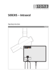
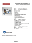
Ironman E Series
Installation, Lubrication and
Maintenance Instructions
A Regal Brand
Phone: 800.894.0412 - Fax: 888.723.4773 - Web: www.clrwtr.com - Email: [email protected]
Important Selection Information
Read ALL instructions and safety precautions prior to operating
unit. Injury to personnel or unit failure may be caused by improper
installation, maintenance, or operation.
Figure 1
MOUNTING POSITION FIGURES FOR
GROVE GEAR E SERIES REDUCERS
Check to verify that the application does not exceed the capacities
published in the current catalog.
Written authorization from Grove Gear is required to operate or use
gear units in man lift or people moving devices.
The system of connected rotating parts must be free from critical
speed, torsional, or other type vibration, regardless of how induced.
The responsibility for this system analysis lies with the purchaser of
the gear unit.
Buyer shall be solely responsible for determining the adequacy of the
product for any and all uses to which the buyer shall apply the product.
The application by buyer shall not be subject to any implied warranties
of merchantability or fitness for a particular purpose.
Grove Gear E Series Reducer Models
These instructions apply to all Grove Gear E Series Reducer Models
18HE to 60HE.
B6
-INPUT VERTICAL/DOWNOUTPUT HORIZONTAL
NOT RECOMMENDED
POSITION
(FACTORY MODIFICATIONS REQUIRED)
FILL & VENT PLUG
Lubrication
LEVEL
All Grove Gear E Series Reducers are splash lubricated. The
unique design of the reducers permits nearly universal mounting by
placing a fill, drain and oil level plug at the proper location for mounting positions. See mounting figures on this page.
DRAIN
V5
-OUTPUT VERTICAL, COVER SIDE UPINPUT HORIZONTAL
(FACTORY MODIFICATIONS REQUIRED)
Review the approved mounting positions and lubrication levels
identified in the Mounting Position Figures in Figure 1. Do not
deviate from the mounting positions or lubrication levels shown
without contacting Factory.
After selecting the position that the unit will be mounted but before
operating: Remove Fill Plug, clean threads on the removed plug and
the plug hole with degreaser. Install Breather Plug securely in gear
case. Note — Plug with breather must always be installed on top most
plug hole of gear case, opposite Drain Plug.
Variations From Normal Conditions
Input speeds higher than 1800 RPM may require an adjustment in oil
level. For vertical output, factory modifications (grease pack and nilos
ring) are required. For input speeds up to 1150 RPM, the high oil level
can be used, without factory modifications. This level, as specified in
the oil capacity chart will be at the center of the top bearing. It can
be checked with a dipstick to obtain the level specified in the chart
from the top housing face.
FILL & VENT PLUG
LEVEL
DRAIN
V6
-OUTPUT VERTICAL, COVER SIDE DOWNINPUT HORIZONTAL
(FACTORY MODIFICATIONS REQUIRED)
Lubricant
Use only Mobil PAG Synthetic oil.
Oil should be changed with regular frequency if unit is used in a severe
environment such as dusty or humid.
Oil, housings, and other components can reach high temperatures
during operation, and can cause severe burns. Use extreme care
when removing lubrication plugs and vents while servicing the unit.
ALLOWABLE MOUNTING ORIENTATION
(WITHOUT FACTORY MODIFICATION)
Phone: 800.894.0412 - Fax: 888.723.4773 - Web: www.clrwtr.com - Email: [email protected]
General Operation
1. Run
the motor which drives the reducer and check the direction of reducer output rotation. Consult motor nameplate for instructions
to reverse the direction of rotation.
2. Attaching
the load: On direct coupled installations, check shaft and coupling alignment between speed reducer and loading
mechanism. On chain/sprocket and belt/pulley installation, locate the sprocket or pulley as close to the oil seal as possible to minimize
overhung load. Check to verify that the overhung load does not exceed specifications published in the catalog.
3. High
momentum loads: If coasting to a stop is undesirable, a braking mechanism should be provided to the speed reducer output
shaft or the driven mechanism.
The system of connected rotating parts must be free from critical speed, torsional or other type vibration, no matter how
induced. The responsibility for this system analysis lies with the purchaser of the speed reducer.
Installation
1. M
ount the unit to a rigid flat surface using grade 5 or higher fasteners. The mounting fasteners should be the largest standard size
that will fit in the base mounting hole. Shim as required under flange or base feet which do not lie flat against the mounting surface.
2. For
shipment, pipe plugs are installed in the unit and a vent plug is packed separately. After mounting the unit in
position, remove the appropriate pipe plug and install the vent plug. Failure to vent the unit can cause premature seal wear
or loss of seal and oil. These conditions are not covered by warranty. Check for correct oil level. Contact the Factory for
level and vent recommendations on non-standard mounting positions. Do not blow pressurized air into the hole, and avoid
spraying washdown chemicals directly into the hole.
3. Connect motor to speed reducer.
E Series helical bevel gear reducers will likely backdrive. Use of a brake or external holding device is required if any evidence of
backdriving is not desired.
Special consideration should be given to high inertia loads connected to the output shaft. Consult the Factory for further details.
Do not operate the reducer without making sure it contains the correct amount of oil. Do not overfill or underfill with
oil, or injury to personnel, reducer or other equipment may result.
A unit cannot be used as an integral part of a machine superstructure which would impose additional loads on the unit
other than those imposed by the torque being transmitted either through a shaft-mounted arrangement, and any shaft
mounted power transmitting device (e.g., sprockets, pulleys, couplings).
For safe operation and to maintain the unit warranty, when changing a Factory installed fastener for any reason, it becomes the responsibility of the person making the change to properly account for fastener grade, thread engagement,
load, tightening torque and the means of torque retention.
Maintenance - Standard Units
Your Grove Gear reducer has been tested and adjusted at Factory. Dismantling or replacement of components must be done by Grove
Gear to maintain the warranty.
1. Frequently
check the oil level of the reducer. If oil level is low, (refer to Figure 1) add proper lubrication through the filler plug until
it comes out the oil level plug.
2. Inspect vent plug often to insure it is clean and operating.
3. Always
check for proper oil level after filling. Do not overfill or underfill with oil, or injury to personnel, reducer, or other equipment
may result. Proper fill quantities in Table 1.
4. Do not mix different oils in the reducer.
Mounting bolts should be routinely checked to ensure that the unit is firmly anchored for proper operation.
Seals
The Grove Gear line of speed reducers utilizes premium quality seals which are the state-of-the-art in sealing technology. Seals are,
however, a wear item and eventually need to be replaced. Replacement can be easily accomplished by following the steps below:
1. Remove
the worn seal without damaging the shaft surface or the seal bore. This can be done by drilling a .062 diameter hole in the
seal casing (being careful not to drill into the bearing behind the seal). Install a #10 sheet metal screw into the hole and pry out the
seal.
2. Clean the seal bore of sealant.
3. Before installing the new seal, use electrical tape to cover any keyways on the shaft to prevent seal lip damage.
4. Grease the seal lips with bearing grease and apply a sealant to the seal bore.
5. Slide the seal into the shaft being careful not to fold the inner lip over on any shaft steps.
6. Press the seal into its bore with a sleeve that presses on the seal casing, being careful to keep the seal square in its bore.
Phone: 800.894.0412 - Fax: 888.723.4773 - Web: www.clrwtr.com - Email: [email protected]
Approximate Oil Capacities
Grove Gear E Series Reducers
If unit is used in the food or drug industry (including animal food)
consult the petroleum supplier or Grove Gear for recommendations
of lubricants which meet the specifications of FDA, USDA and/or
other authoritative bodies having jurisdiction. Standard lubricants
are not suitable for these applications or these industries. Mobil
PAG 460 is approved for USDA/NSF H1 service.
Table 1
Series
18HE
24HE
33HE
43HE
Quantity (Pints)
1.0
2.0
5.0
8.0
Always check for proper oil level after filling. Capacities vary
somewhat with model and mounting position. Oil should rise to
bottom edge of level hole. Do not overfill.
Approved Lubricant Grade
Table 2
Grove Gear Gear Lubricant
Ambient Temperature
Operating Temperature
AGMA Number
IS0-ASTM Viscosity Grade
PAG
-10 to 120 °F
-23 to 52 °C
To 225 °F
To 107 °C
7
460
Mobil PAG 460 H1 Synthetic Lubricant
All standard reducers ordered from Factory are filled with Mobil
Glygoyle 460 polyglycol (PAG) lubricant or equivalent suitable
for continuous option within a -10° F to 120° F ambient temperature range. Double and triple reduction units have separate oil
sumps and must be filled/checked independently. Lubricant type
is stamped on all nameplates.
Mobil PAG 460 H1 Synthetic Lubricant is recommended for E
Series gear reducers in most applications. This lubricant provides
the ultimate efficiency, thermal capacity, and wide operating
temperature range, excellent for low start-up temperatures and
high operating temperatures. Mobil PAG 460 is approved for
USDA/NSF H1 use in food processing facilities where there is
the possibility of incidental contact with food. This fully synthetic
polyglycol lubricant has high thermal and oxidative stability for
longer lubrication intervals, and is well suited for lubed-for-life
applications. The high efficiency reduces operating costs, and the
increased life reduces maintenance costs.
PAG Synthetic Lubricants are not compatible with any other
lubricants, and must never be mixed. Topping off with the wrong
lubricant could cause unit failure.
Food grade lubricants must always be stored separately from
non-food grade lubricants, to prevent the possibility of using the
wrong lubricant. Separate pumps and containers must always be
used with food grade lubricants, to prevent contamination.
Do not operate the reducer without making sure it contains the
correct amount of oil. Do not overfill or underfill with oil, or injury
to personnel, reducer or other equipment may result.
Installation
For safety, purchaser or user must provide protective guards over
all shaft extensions and any moving apparatus mounted on the unit.
The user is responsible for checking and complying with all applicable safety codes in his area and providing suitable guards. Failure
to do so may result in bodily injury and/or damage to equipment.
Wear protective clothing and eye shields when installing or
maintaining unit and machine.
A unit cannot be used as an integral part of a machine
superstructure which would impose additional loads on the unit
other than those imposed by the torque being transmitted, or by
any shaft mounted power transmitting device such as sprockets,
pulleys, or couplings.
Units ARE NOT to be considered fail safe or self locking devices.
If these features are required, a properly sized, independent
holding device must be utilized. Reducers are not to be used
as a brake.
Any brakes that are used in conjunction with a unit must be sized
or positioned in such a way so as to not subject the unit to loads
beyond the capacities published in the current catalog.
Change Intervals
Factory installed synthetic lubricants should be changed only
when performing maintenance that requires gearbox disassembly.
Make certain that all tools and other items are clear from rotating
parts before starting machine. Stand clear, and start machine slowly
to be sure all components are secure and operating properly.
Do not mix nonsynthetic and synthetic oil in the unit.
Overhung loads subject shaft bearings and shafts to stress which
may cause premature bearing failure and/or shaft breakage from
bending fatigue, if not sized properly.
Do not mix PAG synthetic with any other oil type.
Make certain that the power supply is disconnected before
attempting to service or install the unit, or remove or install any
components. Lock out the power supply, and tag it to prevent
unexpected application of power.
Phone: 800.894.0412 - Fax: 888.723.4773 - Web: www.clrwtr.com - Email: [email protected]
Operating Positions
Normal Speed Reducer positions are shown in the Mounting Position
Figures (refer to Page 2). For special applications, mounting position
may be inclined. However, if position varies more than 15°, it may
be necessary to make some adaptions to maintain a sufficient oil
level. Contact Factory for recommendations. Input rotation of Speed
Reducers can be either clockwise or counterclockwise.
For safe operation and to continue the unit warranty, when installing, reinstalling, or replacing a Factory installed fastener for
servicing purpose, or to accommodate the mounting of guards,
shields or other light load imposing devices, or for mounting the
unit, it becomes the responsibility of the purchaser or user to
properly determine the quality, grade of fastener, thread engagement, load carrying capacity, tightening torque, and the means
of torque retention.
Couplings
Flexible couplings to input and output shafts are recommended
because they minimize bearing and gear wear caused by slight
misalignment. Follow coupling manufacturer’s recommendations
for installation and shielding.
Sheaves and Sprockets
When mounting sheaves or sprockets, the center of the load
should be located as close to the reducer as possible. Excessive
overhung loading could result in early failures of bearing or shaft.
Refer to the general catalog or contact your local distributor for
overhung load ratings. Follow manufacturer’s recommendations
for installation and shielding.
Exterior threaded or through holes on this drive are for mounting
the drive or drive accessories (couplings, sprockets, etc.). They are
not to be used for lifting the drive or any driver/driven equipment.
Hollow Output Protective Cover
When installing a hollow output protective cover on washdown
unit, apply a gasket sealant to the face of the cover to prevent
liquid and debris from seeping into the cover.
Excessive setscrew torque may cause damage to the output sleeves
in hollow bore units. Please refer to Table 3 for recommended
tightening torque.
Table 3 - Setscrew Tightening Torques
Capscrew Size
1/4 NC
5/16 NC
3/8 NC
Recommended Torque (lb.-in.)
87
165
290
Test run unit to verify operation. If the unit being tested is a
prototype, that unit must be of current production configuration.
Run-In Period
A new unit will not operate at maximum efficiency during the
run-in period. Increased current draw or heat rise may be seen
during this time.
Preventative Maintenance
Keep shafts and vent plug clean to prevent foreign particles from
entering seals or gear case. Inspect periodically for oil leaks.
Mounting bolts, coupling fasteners, and other power transmitting
devices should be routinely checked to ensure that all parts of the
unit are firmly anchored to provide proper operation (loose fasteners can cause alignment problems and excessive wear). Check
end play in shafts. Noticeable movement might indicate service
or parts replacement is necessary.
If the unit cannot be located in a clear and dry area with access to
an adequate cooling air supply, then precautions must be taken
to avoid ingestion of contaminants such as water, and to avoid a
reduction of cooling ability due to exterior contaminants.
90°
±30°
4A
4
TORQUE ARM FIGURE
Inspect shafts and components for paint, burrs, or other imperfections before installing components. Do not use excessive force or
pounding to install components onto unit shafts, as this may cause
damage to shafts, bearings, or gears.
Shaft Mount Units
The Torque Arm Bracket (4A) can be attached to any of the four
available mounting surface locations of the unit.
Install and position Torque Arm (4) at 90° ± 30° to the plane (a line
drawn) between the center of the output hollow bore and the bolt
that attaches the Torque Arm (4) to the Torque Arm Bracket (4A)
of the unit. The Torque Arm should be positioned to be in tension,
NOT compression, based on output rotation of the gear reducer.
Important Information
In the event of the resale of this E Series Speed Reducer (unit), in
whatever form, resellers/buyers will include the following language
in a conspicuous place and in a conspicuous manner in a written
agreement covering such sale:
The manufacturer makes no warranty or representations,
express or implied, by operation of law or otherwise, as to
the merchantability or fitness for a particular purpose of the
goods sold hereunder. Buyer acknowledges that it alone has
determined that the goods purchased hereunder will suitably
meet the requirements of their intended use. In no event will
manufacturer be liable for consequential, incidental, or other
damages.
Resellers/buyers agree to include this entire document,
including the warnings and cautions listed herein, in a
conspicuous place and in a conspicuous manner to instruct
users on the safe usage of the product.
Phone: 800.894.0412 - Fax: 888.723.4773 - Web: www.clrwtr.com - Email: [email protected]
Electric Motor and Hydraulic Motor and Pump
Installation Instructions
For “C” Flange and Hydraulic Flange Units
1. Check
the bore (input) to be sure it contains an adequate amount of anti-sieze compound, which is normally installed at the Factory.
This compound will inhibit fretting corrosion between the motor or pump shaft and the unit bore.
2. Install the key (if round bore) to the maximum depth of the keyway provided in the bore.
3. Align keyways or splines of motor or pump and bore of unit and install motor or pump into frame.
4. Grove
Gear “C” flange reducers and Hydraulic Flange Reducers are designed to accept motors with shafts that do
not exceed the maximum specified by the N.E.M.A. or SAE standards. If the motor or pump shaft bottoms out before
the motor or pump flange seats against the reducer flange face, the motor or pump shaft length must be adjusted
to NEMA or SAE standards.
5. For
stainless steel and washguard units only, install the o-ring or gasket between the motor and motor flange to prevent water and
debris from seeping in.
6. Secure the motor or pump to the unit. Capscrews and lockwashers are provided with “C” flange units.
7. Tightening torques for mounting bolts are provided in Table 4.
Table 4 - Grade 5 Capscrews
Capscrew Size*
1/4 NC
5/16 NC
3/8 NC
1/2 NC
5/8 NC
3/4 NC
Tightening Torque (ft.-lbs.)
8
16
29
71
143
251
* Grade 5 Capscrews (dry, without lubricant)
A parts list and print for your drive is available upon request. To obtain the proper parts list and print, you must accurately furnish the
assembly number, model number, ratio, style and shipping code as shown on the metal tag attached to the gear drive.
Class of Service
Load conditions must be within cataloged ratings published in the current Grove Gear Catalog (available upon request). Published ratings
assume lubrication with ISO 460 viscosity grade polyglycol (PAG) oil. Contact Factory for ratings when an alternate lubricant is used.
A Regal Brand
Phone: 800.894.0412 - Fax: 888.723.4773 - Web: www.clrwtr.com - Email: [email protected]