1
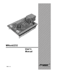
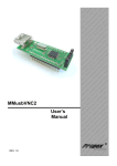
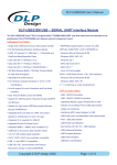
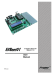
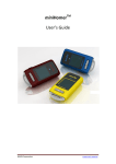
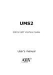
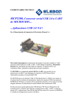
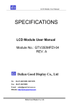
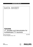
MMusb232
User’s
manual
REV 1.0
u rd ST, ta- rve
l
a oa ,
S e
Ev B VR ers b S l
d
n
io 1, A trol We mo
t
i
a ‘5
in ron ed
r
c
fo cro dd s M the
e
s
d e
i
m mb oar rs, peC E B e S
PI its ng roll gh r
K pi nt Hi fo
r
y
o
rte tot roc FID ers s
o c
r
Pr mi s, R mm lle
rs or ler gra tro
f ol
n
o
s
pr oco CB
e nt r
l
P r
r
u o
o
c tem ic s,
t
m m ds f
s
e
y
n S
T ste ar lS
n
I
,
sy Bo tro
C
d
I
r
n
n
e P
so atio oco eb
,
e
R c
W
r
u
AV pro val mic ed iro E
dd
ic ng PIC be ds m
M ni T, m
r
,
ig , S s E oa rs
s
e
B
t
de VR Ki ng roll
h
t
i
r
, A rte typ on Hig
1
c
‘5 Sta oto ro ID r
e
ic F
rs P
le rs or m s, R mm ve s f ller gra ntrl
r
Se ule tro pro oco
r s,
od on s
m t c tem mic em
i
n ne s T st
y S y
r
ohe In S C, r s B
t
e d
PI eso tion ice
,
e R oc ua m
Sp AV opr val IC e
r r
fo ic g E T, P mb
E
rs s M nin , S
s ing
r ig
t
R
i
e
l
ol des , AV er K typ
B `51 tart roto roS s P mic ,
PC for
s
s ller er for lers
d
l
ar tro erw les tro on b S du con ram
c
ro We imo et rog o
n
p
n
ed Mi her m roc
d
d ds et ste ic
ar rs, Sy T m r
o
B olle In , S so
tr ed IC oce ign
P
s
co Spe R, opr De
V cr B Rion
h
t
ig r A Mi
PC lua
H f o rs
,
s oneasolution
e Many ideas
s
er roll em Ev ds
m nt
st ng oar
y
o
c
S
ni B
Introduction
MMusb232 is low-cost integrated module for data transmission via USB interface. It
is based on FTDI`s FT232BM device. MMusb232 module can work with 1Mboud/s
(RS232), 3Mboud/s (RS422/RS485, TTL) data transfer speed. It’s simply device
witch represents interface between USB and Asynchronous Serial Data Transfer.
There is USB cable attached to module. Windows drivers allows emulate serial port
on PC and that provides to upgrade applications. Choosing our Minimodule is the
first step for projects, which should be done in the short time. MMusb232 could be
used as part of prototype eliminating necessity of designing circuit board and final
circuit in which module is fitted like “sandwich shape”.
MMusb232 is made in two-layer printed circuit board technology with a solid ground
plane. Module includes an integral 93C46 EEPROM on board which is programmable
via USB. All signals are drive via 24 pin, 1.1 in wide footprint. Integral power control
makes the MMusb232 a perfect choice for USB bus-powered, high power designs as
well as self- and low-powered products.
We wish you were successful at designing and using new devices
Features Summary
•
•
•
•
•
•
•
•
•
•
•
•
•
•
•
•
•
•
•
•
•
•
•
•
Single on-board Chip USB - Asynchronous Serial Data Transfer
Full Handshaking & Modem Interface Signals
UART I/F Supports 7 / 8 Bit Data, 1 / 2 Stop Bits and Odd/Even/Mark/Space/No Parity
Data rate 300 => 3M Baud (TTL)
Data rate 300 => 1M Baud (RS232)
Data rate 300 => 3M Baud (RS422/RS485)
384 Byte Receive Buffer / 128 Byte Transmit Buffer for high data throughput
Adjustable RX buffer timeout
Fully Assisted Hardware or X-On / X-Off Handshaking
In-built support for event characters and line break condition
Auto Transmit Buffer control for RS485
Support for USB Suspend / Resume through SLP and RI pins
Support for high power USB Bus powered devices
Integrated level converter on UART and control signals for interfacing to 5V and 3.3V
logic
Integrated 3.3V regulator for USB IO
Integrated Power-On-Reset circuit
6MHZ resonator
Integrated 6MHz – 48Mhz clock multiplier PLL
USB Bulk or Isochronous data transfer modes
4.35V to 5.25V single supply operation
UHCI / OHCI / EHCI host controller compatible
USB 1.1 and USB 2.0 compatible
USB VID, PID, Serial Number and Product Description strings in external EEPROM
EEPROM programmable on-board via USB
•
•
Standard USB connector, B type
Two LEDs (RX, Tx)
Virtual Com Port (VCP) drivers
• Windows 98/ 98 SE / 2000 / ME / XP, MacOS, Linux 2.4 and greater
D2XX (Direct Drivers + DLL S/W)
• Windows 98 / 98 SE / 2000 / ME / XP, Linux
Application Areas
•
•
•
•
•
•
•
•
•
•
•
•
•
USB to RS232, RS422/RS485 converters
Upgrading RS232 Legacy Peripherals to USB
Cellular and Cordless Phone USB data transfer
cables and interfaces
Interfacing MCU based designs to USB
USB Audio and Low Bandwidth Video data transfer
PDA - USB data transfer
USB Smart Card Readers
Set Top Box (S.T.B ) PC - USB interface
USB Hardware Modems
USB Wireless Modems
USB Instrumentation
USB Bar Code Readers
General Description
MMusb232 module is a USB interface that incorporates the functionality FT232BM into a single
24-pin module. A single USB port is converted to RS232 or RS422/RS485 interface, which
allows communicating with greater speed..
By using FTDI’s virtual COM port drivers, the peripheral looks like a standard COM port to the
application software. Commands to set the baud rate are ignored - the device always transfers
data at its fastest rate regardless of the application’s baud-rate setting. Alternatively, FTDI’s
D2XX drivers allow application software to access the device “directly” through a published DLL
based API.
MMusb232 Module Simplified Block Diagram
24-pin footprint
USB B
type
FT232BM
Control
signals
8-bit
3.3V LDO
Resonator 6MHz
EEPROM
Figure 1. MMusb232 block diagram
Functional Block Descriptions
6MHz Oscillator
The 6MHz Oscillator cell generates a 6MHz reference clock input to the x8 Clock multiplier from an
external 6MHz ceramic resonator.
Controller includes:
•
•
•
•
•
•
•
•
•
•
•
•
•
•
•
•
•
•
•
•
•
•
•
•
Integrated Power-On-Reset
Integrated Level Converter on UART interface and control signals
Improved Power Management control for USB Bus Powered, high current devices
Lower Suspend Current
Support for USB Isochronous Transfers
Programmable Receive Buffer Timeout
Improved PreScaler Granularity
Bit Bang Mode
Extended EEPROM Support
USB 2.0 (full speed option)
Multiple Device Support without EEPROM
3.3V LDO Regulator
USB Transceiver
USB DPLL
x8 Clock Multiplier
Serial Interface Engine (SIE)
USB Protocol Engine
Dual Port TX Buffer (128 bytes)
Dual Port RX Buffer (384 bytes)
UART FIFO Controller
UART
Baud Rate Generator
RESET Generator
EEPROM Interface
(More info: www.ftdichip.com)
4
EEPROM memory
The on-board 93C46 EEPROM allows customize the USB VID, PID, Serial Number, Product
Description Strings and Power Descriptor value of the MMusb232 for OEM applications. Other
parameters controlled by the EEPROM include Remote Wake Up, Isochronous Transfer Mode. The
EEPROM is programmable in-circuit via USB using a utility program available from FTDI’s web site
(www.ftdichip.com) and www.propox.com
Module Pin-Out
Figure 2. Pin-Out
Pin Definitions
Pin
1
Pin’s
name
TXL
mode
Description
2
3
PCT
PEN
output
(O.C.)
input
output
LED Drive - Pulses Low when Transmitting Data via USB
4
5
TXE
RI
output
input
6
7
8
9
10
11
DCD
DSR
DTR
CTS
RTS
RXD
input
input
input
input
output
input
Bus Powered – Tie Low / Self Powered – Tie High
Goes Low after the device is configured via USB, then high during USB
suspend. Can be used to control power to external logic using a P-Channel
Logic Level MOSFET switch. Enable the Interface Pull-Down Option in
EEPROM when using the PEN pin in this way.
Enable Transmit Data for RS485
Ring Indicator Control Input. When the Remote Wakeup option is enabled in
the EEPROM, taking RI low can be used to resume the PC USB Host
controller from suspend.
Data Carrier Detect Control Input
Data Set Ready Control Input / Handshake signal
Data Terminal Ready Control Output / Handshake signal
Clear To Send Control Input / Handshake signal
Request To Send Control Output / Handshake signal
Receive Asynchronous Data Input
5
12
15
TXD
RST
output
input
16
RSO
output
18
20
3V3
SLP
output
output
21
RXL
22
23
24
VIO
VEX
VPO
Output
(O.C.)
input
input
output
Transmit Asynchronous Data Output
Can be used by an external device to reset the MMusb232. If not required, tie
to VCC.
Output of the internal Reset Generator. Stays high impedance for ~ 5ms after
VCC > 3.5V and the internal clock starts up, then clamps its output to the 3.3v
output of the internal regulator. Taking RESET# low will also force RSTOUT#
to drive low. RSTOUT# is NOT affected by a USB Bus Reset.
3.3 volt Output from the integrated L.D.O. regulator.
Goes Low during USB Suspend Mode. Typically used to power-down an
external TTL to RS232 level converter i.c. in USB <=> RS232 converter
designs.
LED Drive - Pulses Low when Receiving Data via USB
+3.0 volt to +5.25 volt VCC to the UART interface pins
Set main power supply, should be connect to VPO if powered from USB port
Power supply from USB
Technical Data
Dimensions
Weight
Power supply
: 45mm x 20mm x 15mm
: ~ 60 g
: 5V
Mechanical Dimensions
Dimensions are in miles.
1miles – 1/1000 inch
100miles = 2,54mm
6
Standard Device Configuration Examples
USB Bus Powered and Self Powered Configuration
Power
supply
15
15
22
23
24
22
23
24
Figure 3a. USB Bus Powered
Figure 3b. External Powered
Figure 3a illustrates a typical USB bus powered configuration. A USB Bus Powered device gets its
power from the USB bus. Basic rules for USB Bus power devices are as follows:
a) On plug-in, the device must draw no more than 100mA
b) On USB Suspend the device must draw no more than 500uA.
a) A High Power USB Bus Powered Device (one that draws more than 100mA) should use
the on-board MOSFET to keep the current drawn by external circuitry to below
c) ~70mA on plug-in and ~200uA on USB suspend
d) A device that consumes more than 100mA can not be plugged into a USB
e) No device can draw more that 500mA from the USB Bus.
f) No device can draw more that 500mA from the USB Bus. The power descriptor in the
EEPROM should be programmed to match the current draw required by the device.
A Ferrite Bead is connected in series with USB power to prevent noise from the device
and associated circuitry (EMI) being radiated down the USB cable to the host.
Figure 3b illustrates a typical USB self powered configuration. A USB Self Powered device gets its
power from its own Power Supply and does not draw current from the USB bus. Basic rules for USB
Self power devices are as follows:
a) A Self-Powered device should not force current down the USB bus when the USB
Host or Hub Controller is powered down.
b) A Self-Powered device can take as much current as it likes during normal operation and
USB suspend as it has its own power source.
c) A Self-Powered device can be used with any USB Host and both Bus and Self Powered
USB Hubs.
The USB power descriptor option in the EEPROM should be programmed to a value of zero (self
powered).
If interface between MMusb232 and device must be 3.3v logic level, then 22 pin, should be
connected to +3.3V voltage.
7
Bus powered circuit with power control – 5V power supply
FT232BM
Microcontroler
VIO
SLP
VEX
VPO
Technical support
If You have problem with MMusb232, please contact us at [email protected].
8
Schematic
USBVCC
FB1
FERRITE BEAD
1
EXTVCC
2
C1
10nF
C3
10uF
R1
470R
PORTVCC
DM
DP
USBDM
8
R8 See Table
5
27
X1
R6
See Table
C9 6MHz
27p
TEST
FT232AM
RESETO FT232 BM
28
4
C10
27p
31
32
1
2
RESET
R12
See Table
Table: Component value selector
FT232AM
R6
R7
R8
C8
R12
R14
0R
1k5
None
100nF
100k
100k
FT232BM
None
None
1k5
0R
None
None
13
VCC
TEST
XTIN
XTOUT
RESET#
RCCLK
EECS
EESK
EEDATA
TXD
RXD
RTS#
CTS#
DTR#
DSR#
DCD#
RI#
TXDEN
USBEN
PWRCTL
TXLED#
RXLED#
USBVCC
RCCLK
VCC
3
USBDM
29
USBVCC
USBDP
GND
7
17
USBDP
3V3OUT
GND
R5 27R
30
6
R4 27R
9
R7
See Table
AVCC
J1
USB-B
VCC
C11
33nF
26
3V3OUT
AGND
1
2
3
4
IOVCC
USBVCC
EECS
EESK
EEDATA
R13
10k
R15
2k2
TXD
RXD
RTS
CTS
DTR
DSR
DCD
RI
16
15
14
12
11
TXDEN
PWREN
PWRCTL
TXLED
RXLED
C5
C6
C7
0.1uF
0.1uF
0.1uF
0.1uF
TXLED
PWRCTL
PWREN
TxDEN
RI
DCD
DSR
DTR
CTS
RTS
RxD
TxD
U2
FT232AM/BM
USBVCC
1
2
3
4
U1
CS
SK
DIN
DOUT
VCC
NC
NC
GND
8
7
6
5
1
2
3
4
5
6
7
8
9
10
11
12
J2
1
2
3
4
5
6
7
8
9
10
11
12
20
19
12
17
20
19
18
17
16
15
14
13
24
23
22
21
20
19
18
17
16
15
14
13
PORTVCC
EXTVCC
IOVCC
RXLED
SLEEP
GND
3V3OUT
GND
RESETO
RESET
GND
NONE
DIP24
10 SLEEP
SLEEP#
R14
See Table
C8
See Table
25
24
23
22
21
20
19
18
C4
D1
RXD
D2
TXD
R2
270R
R3
270R
J4
RxLEDEN
J5
TxLEDEN
IOVCC
IOVCC
93C46
http://www.propox.com
email: [email protected]
Title: USB - SERIAL UART Interface Module
Size:
Date: 20-10-2002
9
Rev:
File:
Sheet 1 of 1
1.00