1
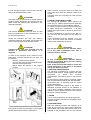
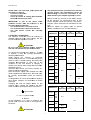
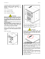
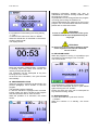
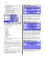
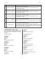
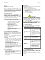
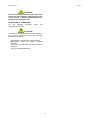
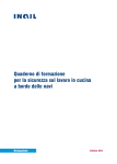
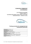
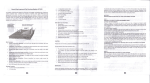
E101102X rev2
04/07/11
WASHING MACHINES
INSTALLATION
USE AND MAINTENANCE
INSTRUCTIONS
IMESA S.p.A.
Via degli Olmi, 22
31040 Cessalto (TV), ITALY
tel. +39.0421.468011
fax +39.0421.468000
www.imesa.it
1
E101102X rev2
04/07/11
Index
1. INTRODUCTION ............................................................................................................................................3
2. SAFETY RULES .............................................................................................................................................3
3. MANUFACTURER RESPONSABILITY .........................................................................................................4
4. UNPACKING ..................................................................................................................................................4
5. INSTALLATION AND PLACING.....................................................................................................................5
6. MACHINE IDENTIFICATION .........................................................................................................................5
7. NOISE.............................................................................................................................................................5
8. GROUND FIXING ...........................................................................................................................................5
9. ELECTRIC CONNECTION.............................................................................................................................7
10. HYDRAULIC CONNECTION: LOAD ............................................................................................................8
11. HYDRAULIC CONNECTION: DRAIN ..........................................................................................................8
12. STEAM CONNECTION ................................................................................................................................8
13. COMPRESSED AIR CONNECTION ............................................................................................................9
14. MASCHINE START AND FINAL TEST........................................................................................................9
15. LANGUAGE CHANGE .................................................................................................................................9
16. REMOTE ASSISTANCE SERVICE ACTIVATION .....................................................................................10
17. WASHING MACHINE USE ........................................................................................................................10
18. LINEN PREPAIRING ..................................................................................................................................11
19. HOW TO LOAD THE MACHINE AND CLOSE THE DOOR ......................................................................12
20. DOOR MANUAL OPENING .......................................................................................................................12
21. MACHINE SWITCH ON .............................................................................................................................12
22. SELECT A PROGRAM...............................................................................................................................13
23. PREFERRED PROGRAM LIST .................................................................................................................13
24. DELAYED START ......................................................................................................................................13
25. PROGRAM EXECUTION ...........................................................................................................................14
26. PROGRAM PAUSE ....................................................................................................................................14
27. RAPID ADVANCE ......................................................................................................................................14
28. END OF WORKING DAY ...........................................................................................................................15
29. PROGRAM .................................................................................................................................................15
30. PROGRAM MODIFICATION ......................................................................................................................15
31. EASY PROG...............................................................................................................................................17
32. SELF DIAGNOSTICS .................................................................................................................................19
33. PROGRAM SET BY THE FACTORY .........................................................................................................21
34. OTHER FUNCTION ...................................................................................................................................22
35. WASHING MACHINE MAINTENANCE .....................................................................................................22
36. WASHING DEFECTS.................................................................................................................................22
37. TILTING MACHINE USE ............................................................................................................................22
38. SAFETY DEVICES CONTROL ..................................................................................................................23
39. SCRAPPING ..............................................................................................................................................23
40. WARRANTY CONDITIONS ......................................................................................................................24
2
1. INTRODUCTION
This manual is addressed to explain industrial
washing machine use.
It is written in compliance with actual EU
directives.
The information here written is addressed to the
installer and to the user, which must fully
understand them before to work on the machine.
The user manual must always be available to be
consulted. In case of missing or damaging of the
manual, ask to the manufacturer for a new copy.
The manufacturer is not responsible for any
consequence coming from a not correct use of the
machine because of a misreading or a not
complete reading of this manual.
The manufacturer reserves itself the right to
modify the here written machine specification or
characteristic without any previous notice. The
pictures of this manual may differ from reality for
some detail, which could be partially different from
the one mounted on the machine. Diagram and
technical data may be modified without any
previous notice.
The manual and its attachment are part of the
manual themselves, so they must be kept and
they must follow the machine in case of sale to
another user.
Attachments and exploded view with spare parts
list can be retrieved in IMESA web site restricted
area. Before to access to the manufacturer
technical area be sure that the machine serial
number is available.
ATTENTION!
The manufacturer declines any responsibility
about possible errors contained in this manual
because of printing, translation or writing
imprecision.
The manufacturer reserves itself the right to make
any necessary modification to the machine
without
affecting
any
machine
essential
characteristic.
It is forbidden the copying, also partially, of the
text or of the pictures of this manual without any
previous manufacturer authorization.
2. SAFETY RULES
The missing observance of the below safety rules
may cause damages to people, things and
animals.
The here described machines installation and
maintenance must be done by authorized
personnel, who know the product and in
compliance with EU directives of sector.
Reparation made in a not correct way may be
dangerous for the user.
Before to put in service the machine, this
instructions must be read with high attention. This
document must be available to everyone is using
the machine.
The here described machine are addressed to the
professional washing of garments and linen: it is
forbidden any other use of the machine if not
previously authorized by the manufacturer.
Do not washed linen soaked with substances
which are dangerous for the user health like
poison or cancerous products.
Do not approach the machine with combustible or
inflammable substances to avoid the risk of fire or
explosion.
Always stick to the washing instructions of the
linen label.
The use of this machine is forbidden to people
under 16 years age.
Not properly done external connection to the
machine release the manufacturer from any
responsibility.
IMPORTANT NOTES
Working with opened sides is forbidden!
In order to avoid burnings or accident it is
forbidden to remove, even temporarily, the
protection panels and the safety systems!
It is forbidden to introduce bars, sticks or
metallic objects inside the drum. In case of
emergency, please refer always the here
described procedures.
Each time the machine is started, check
always the safety device correct working!
It is compulsory to know the machine and how
its safety devices are working!
BURNS DANGERS
The machine, because of its nature, presents
burns danger.
Burns may be caused by:
- A long contact with door during a high
temperature program;
- The contact with the fluxing steam parts.
E101102X rev2
04/07/11
avoided because of the risks of dangerous knocks
against the washer chassis, i.e.: during the dryer
unloading.
The other people in the laundry room do not have
to distract the operator, who is working on the
dryer.
While working, the operator does not have to be
distracted by TV, radio or any source of
distraction.
On the machines are fixed the following labels,
if one of them should be damaged, the user
must replace it with a new identical one.
ILLUMINAZIONE
LIGHTING
In the room where the machine is installed, the
lighting must be at least of 300-500 lux intensity;
unpleasant flashing must be avoided.
Near the door
ATTENTION!
These instructions do not cover all possible risks.
User must always pay high attention and respect
carefully the rules.
Machine must always be used by trained
personnel and with at least one other operator
in the room!
3. MANUFACTURER RESPONSABILITY
The instructions written in this manual are not
replacing, but completing the duties deriving from
the safety and accident prevention laws. With
reference to what is written in this manual, the
manufacture is not responsible for:
- a use of the machine against the safety and
accident prevention laws in force.
- not correct machine installation.
- missing of periodical and programmed
maintenance.
- not observance, or not correct observance, of
this manual instructions.
- electrical supply fault.
- not authorized modification of the machine.
- use of the machine by not authorized
personnel.
READ CAREFULLY THE INSTRUCTION FOR
OPERATING IN CASE OF BLACK OUT, AND
INFORM ALL THE USERS ABOUT THEM.
ELECTROCUTION DANGER
Any service on the electrical parts must by
operated only by qualified personnel. Before
to work on the machine, cut off the electrical
supply.
Power and controlled circuits can be modified
only by manufacturer personnel, on the
contrary the warranty condition empire.
On the electric board, the here below warning
label was stuck. If this label should be damaged
or unstuck, it needs to be replaced by an identical
one.
4. UNPACKING
The machine must be controlled at the delivery
moment, any external or inside damage dues to
the transport, must be reported immediately to the
forwarder.
400V
The machine must be completely unpacked next
to the installation position. The packing material
must not be spread on the environment, but must
be collect in the appropriate collecting place as
per the environmental directives.
Using a monkey spanner, take off the bolts fixing
the machine to the pallet.
OPERATOR PSYCHO-PHYSICAL
CONDITIONS
People using the machine must be in a perfect
psycho-physical condition; during the working
cycle, the user must always assume a vertical
posture in front of the machine.
Suddenly or not controlled movement must be
ATTENTION!
Check the technical data sheet, which is sent
together with the machine documents, to control
4
E101102X rev2
04/07/11
When removed, the locks need to be kept and
used again each time the machine needs to be
moved.
Transport locks are not present in hard mounted
machines.
the net and gross weight: check if they meet the
data of the available lifting means.
ATTENTION!
The pallet must not be used as a normal machine
support! Always take down the machine from the
pallet. Install the machine has described in the
opposite paragraph.
During the transport, the high spin washing
machines basement and cradle are blocked with
locks in order to avoid shock absorber stress.
5. INSTALLATION AND PLACING
Any placing and installation action needs to be
made only by qualified personnel and respecting
the instructions given in the installation manual.
To assure a correct machine use and working and
to make easier the maintenance, a at least
600mm free space need to be left all around the
machine.
In case of installation of machine in line, like in a
coin op shop, the side space can be reduce to
10mm.
Room temperature bust be between +5°C and
+40°C. The room where the machine is installed
need to have a sufficient air recycle.
ATTENTION!
Transport locks need to be removed once the
machine is positioned and before it is
supplied.
ATTENTION!
DO not use or stock near the machine petrol,
oil or any other inflammable stuff. Fire or
explosion may be caused.
ATTENTION!
The machine must be moved only when it is still
fixed on its pallet and, in case of forklift truck, only
by authorized personnel.
To take off the transport locks, follow the next
instructions. Pictures indicate the lock type, not
the machine.
Remove frontal and rear panels.
Unscrew the bolts fixing the transport locks.
Remove the transport locks
Mount again the panels in the original
position.
ATTENTION!
In case of tilting machine, machine element
may be in movement during the linen loading
and unloading operation.
Refer to the technical data sheet to control the
overall dimension of the parts in movement
during the different position.
6. MACHINE IDENTIFICATION
The machine is identified by a sticker with the
machine serial number, model together with other
information
i.e.
power
and
technical
characteristics. The label is stuck on the machine
back.
Be sure that any supply (electric, hydraulic, steam
and compressed air) matches with the label data.
Spare parts and / or servicing need the correct
model individuation.
Warranty automatically expires if the sticker is
damaged, removed, missing or not readable. In
one of these condition installation and servicing
operation may be difficult because of the machine
cannot be correctly identified.
7. NOISE
The air noise produced by the machine gives an
acoustic pressure continued and weighted of level
A below 72 dB.
8. GROUND FIXING
High spin washing machine with capacity up to
23Kg do not need any ground fixing. Machines
are supplied with rubber feed which need to be
screwed to the threaded holes on the machine
Each panel must be mounted again in the original
position before the machine is switched on.
5
E101102X rev2
04/07/11
base.
-
A wrong adjusting of the feeds may cause strong
vibration of the machine external structures. The
machine must be installed in a perfect level on a
floor without any elastic reaction.
-
screws.
Move the machine to make free the area to
make the holes.
Make the holes (see the picture) where the
position is marked, and following the data of
the next table.
High spin washing machine starting from 30 kg
capacity must be fixed on the ground using four
Fischer wall plugs and making them pass through
the holes on the machine base. Machines need to
be installed in a perfect level on a floor without
any elastic reaction.
ATTENTION!
Do not insert any elastic stuff between the
machine base and the floor.
Low spin washing machines must be ground
fixed.
Starting from 30 Kg capacity, low spin washing
machines are supplied with an iron frame.
- The frame must be let into a concrete base,
which is opportunely anchored to the floor.
- Before to anchor the machine to the base, be
sure that the concrete set well to the ground
and, very important, be sure that the frame is
perfectly in level.
- Place the machine in the suitable anchor holes
and close all the bolts.
To control frame and concrete base dimension,
check the machine technical sheet.
Up to 23Kg capacity, the washing machine are
supplied with iron anchor screw.
Lt
S
Øf
P
Hv
Ch
M
-
iron anchor screw
-
Tools necessary for installation are:
- Hammer or electro-pneumatic drill
- Hammer
- Pump for cleaning
- Brush
- Dynamometrical spanner
Please, follow the below described procedure:
- Make a concrete base which need to be well
anchored to the floor, respect the technical
data sheet specification;
- Be sure that the concrete base is well set to
the ground, the surface need to be perfectly in
level.
- Bring down the machine from the pallet and
place it in the final position on the concrete
base.
- Through the open panels, mark on the
concrete base the position of the anchor
-
Anchor screw length
Fixable object
thickness
Drill diameter
Minimum hole depth
Anchor minimum hole
Key
fixing couple
thread
138
25
mm
mm
18
140
80
19
80
M12
mm
mm
mm
Nm
-
Extract the concrete residual from the hole
using a brush, using a pump make free the
hole from the residual dust.
Place again the machine matching the washing
machine base hole with the concrete base
holes.
Introduce the anchor bolts through the washing
machine base holes inside the concrete base
holes.
Using a dynamometric spanner close the
anchor screw following the data in the above
table.
ATTENTION!
Each installed low spin machine must be
6
E101102X rev2
04/07/11
Th
he machine must be co
onnected to an efficientt
grround system: the manufacturerr refuse alll
re
esponsibility
y in case tthis connec
ction is nott
made
m
following the subje
ect regulatio
on in force.
tested with
h a full loa
ad spin (ma
ax speed an
nd
max load), to check if:
- There is
s no vibratio
ons
- There is
s no noise
- There is
s contact or
o sliding point
p
betwee
en
the drum
m and the outer drum.
Be
efore to starrt any service
e, cut the ele
ectric supplyy
to
o the machine: for ma
aintenance refer
r
to the
e
electric diagra
am inside the machine. The electricc
diagram can be
b retrieved from manuffacturer web
b
site.
Minimum
M
secction for su
upply cable or ground
d
ca
ables, expresssed in mm2 are the follo
owing:
IMPORTAN
NT: if one
e of the above liste
ed
problems occurs, the
en the ma
achine is not
n
correctly in
nstalled. Check if:
- The con
ncrete base is correctly at level
- The con
ncrete base is well set to the floor
- The iro
on anchor screws are
a
correcttly
closed.
CAPACITY
9. ELECTR
RIC CONNEC
CTION
The electrical connecttion must be
b realized by
ersonnel and
d it must co
omply with the
t
qualified pe
local and na
ational regula
ation in force
e.
Low spin
High spin
Low spin
ATTENTION!!
A
sion matches
Be sure that the supplied tens
ne indicated on the mac
chine label.
with the on
High spin
6
8
6
11
14
10
3ph
208V-240V
V
3ph
380V-440V
V
4
6
4
10
6
16
Low spin
To connect the machine
e use a H05
5 VV – F cab
ble
or superiorr, it must be
b correctlyy dimensioned
following the
e data label.
Install before the machine a omnipolar
disconnectin
ng device (i.e.: a circuit breaker)
b
which
need to ha
ave a contacct opening that allows the
t
complete disconnectio
d
on in case one of the
t
conditions of the ove
er tension III category is
verified. This device mu
ust comply with
w the subje
ect
regulation in
n force.
Check the main
m
switch,, it must be in position “0
0”.
Open the ellectric supplyy door.
Pass the electric supply cable thro
ough the cab
ble
plied with the
e machine. The
T cable mu
ust
holder supp
be correctly dimension
ned (check the following
table).
ento dei cavvi di alimenta
azione elettrica
Il collegame
deve esserre eseguito sul seziona
atore di borrdo
macchina.
Following the
t
kind off voltage written
w
on the
t
machine la
abel, connecct the cable
e to the kn
nife
switch conta
acts, followin
ng the below instructions:
1ph
V
208V-240V
18
High spin
NO
Low spin
16
23
High spin
Low spin
16
30
High spin
10
NO
Low spin
40
High spin
25
Low spin
High spin
55
70
85
16
Electric
E
heating or electricc / steam hea
ating (mm2)
CAPACITY
: ground boltt
Low spin
L1, L2, L3: phase conta
act
High spin
N: neutral
n
At the installation, or in case of replacing, the
t
ground cab
ble must be at least 5 cm
c longer than
the others
6
8
11
14
1ph
V
208V-240V
3ph
208V-240V
V
3ph
380V-440V
V
2,5
2,5
Low spin
18
NO
High spin
Low spin
A
ATTENTION!
!
7
23
2,5
E101102X rev2
CAPACITY
04/07/11
1ph
208V-240V
3ph
208V-240V
case it is requested, the machine is equipped with
a third electrovalve for hard water). Each water
inlet is identified, for connection quotes refer to
technical data sheet.
At the beginning of each hydraulic supply a gate
valve must be provided to cut the water supply to
the machine at any moment, in case of
emergency or in case of service.
At the beginning of each water inlet an inspect
filter must be provided. It is necessary, also, to
control the machine inlet valve filter after a short
time of use, overall the hydraulic system is old or
not used from a long time.
3ph
380V-440V
High spin
Low spin
30
4
High spin
Low spin
40
High spin
NO
Low spin
6
55
ATTENTION!
All the inlet valve must always be connected!
If in the supply system it is not available the
hot water, connect cold water also to the inlet
valve called “HOT WATER”.
High spin
6
Low spin
70
High spin
10
When more washing machine are connected to
the same water line, the water line must have a
diameter sufficient to grand a water flow enough
to supply all the machine in case all of them are
loading water.
A minimum pressure of 0,4 atm is necessary to
load the water: if the supplied pressure is lower,
the water loading time are longer.
Maximum water loading pressure is 8 Atm (the
minimum and maximum values are taking in
consideration all the kind of valve mounted on the
different machine size).
Low spin
85
High spin
Steam or Hot Water heating (mm2)
ATTENTION!
The minimum sections written in the above tables
can be change in function of the cable length. For
cable longer than 5 mt, increase proportionally the
section in respect of the additional length.
11. HYDRAULIC CONNECTION: DRAIN
The electric drain valve used are a normally open
kind, it means that the water is drained in case of
black out.
In case of more washing machines connected to
the same drain line, it must be enough to allow the
correct water flow in case all the machines are
draining water at the same time.
Drain collector must avoid that the water drained
by one machine enter in the next one.
The washing machine drain is for gravity, the
drain tube must not present sinking or
counterslope. A 2% slope must be provided to
allow a correct water flow.
The drain system must satisfy the local or national
laws and regulation in force.
ATTENTION!
The machine connection must always be done on
the base of the serial number label (power,
supplied tension, frequency). For supplied tension
different from the one provided, please contact the
manufacturer.
ATTENTION!
All washing machines are equipped by a speed
control operated by an inverter: a protection
through RCD – B kind device must be provided
(sensitive to average current value).
ATTENTION!
In case the electrical supply come from a diesel
generator, then the inverter ask for the application
of an additional inductor.
12. STEAM CONNECTION
In case of machine steam heated a steam
connection must be provided.
The steam connection must be operated by
qualified personnel and must satisfy the local and
national rules in force. Check that the steam has
the same characteristics written in the technical
data sheet and that all the system parts are
certified.
10. HYDRAULIC CONNECTION: LOAD
The washing machines are equipped with
electrovalve for the cold and hot water loading (in
8
E101102X rev2
04/07/11
4)
5)
6)
7)
8)
The steam trap is delivered with the machine, but
not mounted on the machine: the steam trap
electrical and hydraulic connection is at installer
charge.
ATTENTION!
Once the steam trap is connected to the machine,
it must be protected by the supplied iron box: see
the following picture.
inlet steam gate valve
steam trap
check valve
flow control
exit gate valve
ATTENTION!
The machine can work with a steam pressure
between 0,5bar and 4,5 bar. Lower is the
steam pressure, longer is the heating time.
13. COMPRESSED AIR CONNECTION
Connection to compressed air is necessary only
for some model: check the technical data sheet.
System must be performed by qualified personnel
in compliance with national and local rules in
force. Each connection between the system and
the equipment must be tightness tested; use a
leak finder spray, if there is any leak, it needs to
be repaired.
14. MASCHINE START AND FINAL TEST
Once the machine is installed, and all connections
are made, it must be started following the
provided instructions.
Each machine part must be tested: start a
program and check at least one complete
program. The machine must be fully loaded and,
in case of high spin machines, the unbalance end
switch position must be controlled
The supply steam system must be realized
following the next diagram.
Each connection between the system and the
equipment must be tightness tested.
A) machine
B) external system
C) steam supply system
15. LANGUAGE CHANGE
When the machine is switched on for the first
time, interface language could be different from
the one wished by the user.
The following procedure explains how to change
the interface language.
Touch the icon “MENU” of the home page.
Indirect steam heating
The display shows:
Direct steam heating
System elements are identified as follow:
1)
2)
3)
washing machine
inlet steam valve(supplied with the machine)
filter
9
E101102X rev2
04/07/11
Touch the icon “PARAMETERS”, the display
shows:
Digit the code “111111” and the display shows:
Touch the icon MODIFICA and scroll the menu of
the available languages using the keys “<<” and
“>>”. When the whished language appears on the
screen, confirm touching the icon “OK”.
Exit the configuration menu touching the icon
“HOME” as many time as necessary to reach the
home page.
Point 1: detergent box access door.
In the lower capacity machines, the three
compartment prewash (P), wash (W), softner (S)
are marked by the rubber cover inside.
16.
REMOTE
ASSISTANCE
SERVICE
ACTIVATION
In case of models equipped with the remote
assistance system, the connection to the service
server must be activated. In order to do it, check
the instructions sent with the machine.
17. WASHING MACHINE USE
Some machine parts must be known before to use
the machine for the first time.
The following generic pictures are resuming the
possible configuration.
10
E101102X rev2
04/07/11
In the higher capacity machines, are available four
carafes to load powder or liquid detergents.
Detergent loading moments, and opening of
detergent
corresponding
valve,
can
be
programmed.
Point 2: computer display.
Point 3: USB door (A type).
Point 4: emergency stop button.
ATTENTION!
When the emergency stop button is pressed,
the electrical supply to machine control is cut.
The display switch off and the cycle is
automatically interrupted: the turning drum is
stopping because of inertia and the tank is
emptied.
Emergency stop button must be pressed only
in case of danger.
When the emergency situation is finished, the
stop button need to be turned right to be
armed again. The display switch one and the
cycle stand by waiting for the START.
When the main switch is in position “I”, the
machine is electrically supplied.
When the main switch is in position “0” the
machine is not electrically supplied.
Point 5: machine door hole. In the following
paragraphs are described the different kind of
locking system which could equipping the different
models.
ATTENTION!
The air inlet on the machine back, and
possibly also on the machine upper panel,
must always kept free. Air pass must not be
stopped or limited!
Point 6: main switch.
18. LINEN PREPAIRING
Machine must be loaded on the base of the serial
number plate: it must not be loaded with a weight
higher than the one written in the technical data
sheet or in the serial number plate.
Before to chose the most suitable program, the
linen need to be sorted into groups homogeneous
for fibers and fabrics, in order to have a uniform
washing for the whole load.
Before to put the linen into the washing machine,
be sure that the linen label is authorizing the
machine washing; always stick to linen
manufacturer indication.
Here below the meaning of the most common
International symbols:
11
E101102X rev2
04/07/11
Maximum temperature
e: 70°;
Mechanica
al action: mid
dle.
Maximum temperature
e: 60°C;
Mechanica
al action: sofft
Maximum
tempera
ature:
Mechanica
al action: verry soft
40°°C;
Only hand
d washing
Not washing
T LOAD TH
HE MACHINE
E AND
19. HOW TO
CLOSE THE DOOR
The machine must be
b loaded following the
t
indication given in the se
erial numberr plate.
The label iss stuck on the
e machine ba
ack.
n case of macchine with m
motorized lock
king:
In
ta
ake off the cover
c
(see th
he picture) and
a
insert a
so
ocket box wrrench (4mm). Turn rightt the wrench
h
un
ntil the door opens.
o
A
ATTENTION!
!
Machine must be loade
ed with linen
n, which is the
t
most homo
ogeneous po
ossible. The weight of the
t
loaded line
en must nott be higher than the one
indicated in
n the techniccal data she
eet and in the
t
serial numb
ber sticker.
Before to lo
oad the linen
n, be sure th
hat the drum is
completely empty. Whe
en the mach
hine is loade
ed,
close the do
oor.
A
ATTENTION!
!
at no linen pa
arts are take
en between the
t
Be sure tha
door and th
he machine front
f
panel, while the do
oor
is going to be
b closed.
In case of machine
m
without door han
ndle, just pre
ess
the door against the ma
achine until it is locked.
m
with
h handle or motorized
m
do
oor
In case of machine
lock, the do
oor must justt drawn closse the machine
front, in th
his way the closing pin
n enter in the
t
correct posiition on the machine
m
fron
nt.
When the machine is started the computer will
w
give the com
mmand to locck the door.
ATT
TENTION!
pply electric
city to the machine,
m
alll
Before to sup
he protectio
ons must be
e mounted again
a
in the
e
th
orriginal posittion!
1. MACHINE
E SWITCH O
ON
21
Tu
urn the mach
hine main sw
witch in positiion on.
M
OP
PENING
20. DOOR MANUAL
While the cycle
c
is running it could be possible to
open the door
d
manually, without the
t
use of the
t
unlock key on
o the machine touch sccreen.
In
n case of stea
am heated m
machine, ope
en the steam
m
ga
ate valve. To
T limit wate
er hammering
g cases, the
e
va
alve must be
e open slowlyy passing fro
om the close
e
po
osition to ope
en position in
n 1 minute tim
me.
Th
he emergen
ncy stop bu
utton must be in restt
po
osition; contrrol that the e
emergency stop
s
was nott
ac
ctivated durring the tra
ansport or before the
e
machine
m
was switched off last time.
TTENZIONE
E!
AT
d
cut the
Before to open manually the door,
s
from
m the main switch.
s
electricity supply
In case off machine without
w
hand
dle. Open the
t
below front panel. In orrder to open
n the door, pull
p
down the sttring with ring
g on the left side.
s
Be
efore to sta
art the macchine always
s check the
e
sa
afety system (refer to the
e related para
agraph).
12
E101102X rev2
04/07/11
touch it, the line background will become blue
(example: program 3):
When the machine is switched on, the software
version, as well as its release date, appear on the
screen for a while.
The software loading could ask for a minute time,
more or less.
The request of machine loading appears on the
screen:
Once “OK” is touched, the selection is confirmed
and the following information appears on the
screen:
Load the machine as requested in the relative
paragraph and close the door following the
previous given instruction
22. SELECT A PROGRAM
When the machine is loaded and the door is
closed, the main MENU screen appears:
Touch “START”.
23. PREFERRED PROGRAM LIST
From the main menu, touching the icon
“PREFFERED” it is possible to visualize two
program lists:
- the last used program list;
- the list of program set as preferred by the
user.
The program selection is done as described in the
relative paragraph.
To set a program as preferred, please refer to the
on-line manual.
Touching the icon “PROGRAMS” the programs
list appears:
24. DELAYED START
If you want to program a delayed start of a
program, select the program as described before,
then touch the icon “COUNT”
The screen shows:
It is possible to scroll down the program list using
the bar on the right side. Otherwise, it is possible
to go ahead line by line touching the arrows on
the right side.
Once the wished program appears on the screen,
13
E101102X rev2
04/07/11
Displayed information enables the user to
understand the machine working conditions while
the program is running.
All parameters can be changed while the program
is running just touching the relative icon.
These modifications stay valid only for the running
program. For more information about this function,
please refer to online documents.
ATTENTION!
In case of anticipated conclusion of the cycle,
remember that the linen temperature may be
very high!
It is possible to fix the starting time using the key
“+” and “-“.
To exit from this menu touch the icon “BACK”.
When the wished time is visualized on the screen,
confirm it touching OK.
The display shows:
ATTENTION!
In case of not correct machine working, switch
off the equipment and call the authorized
service centre!
26. PROGRAM PAUSE
While the program is running, it is possible to put
it in stand by just touching the icon “PAUSE”.
The screen shows:
Below the indication of delayed start, a countdown
is showing how many hours and minutes are
missing to the automatic start.
The countdown can be interrupted at any time
touching the icon “STOP”.
At the end of the countdown, the cycle will start
automatically.
25. PROGRAM EXECUTION
When the program is selected, as described in the
previous paragraph, touch “START” to start the
program.
The selected program is started.
In case the machine is equipped with motorized
locking system, the door is locked, at the program
start, this operation ask for some seconds.
While the operation is in execution, the screen
shows:
It is highlighting the soak step and its length.
Soak can be interrupted and the cycle started
again touching the icon “START”.
During the soak, the cycle can be interrupted at
any moment touching “STOP”.
27. RAPID ADVANCE
To move fast inside the cycle touch the icon
“>>FFWD”.
While the machine is in standby, the screen
shows:
14
E101102X rev2
04/07/11
program area. The screen shows:
Here below the symbol meaning:
“I◄◄”
Fast back per cycle
“◄◄”
Slow back per step
“►”
Start again the cycle
“►►”
Slow advance per step
“►►I”
Rapid advance per cycle
NOTE: the USB communication icons appears
only if a USB key is connected and recognized by
the system.
To change an existing program touch the icon
“MODIFICATION”.
The screen shows the programs list, scroll the list
as explained in the paragraph referring to program
selection. Select the wished program, the line
background will become blue (example:
PROGRAM 1).
In the middle of the below bar on the screen, it is
written the percentage of program advance.
28. END OF WORKING DAY
At the end of the working day, the machine must
be brought at the end of the cycle and switch off,
the drum must be cleaned and no linen must be
left inside the drum.
Cut any supply to the machine using the suitable
switch/knife switch: electricity, steam and
compressed air.
Leave the door open.
29. PROGRAM
Program function allows to modified the existing
program or to create new programs.
A program is composed by a sequence of steps,
which can be modified in anyone of their
parameters.
When the wished program is selected, confirm the
choice touching the icon OK.
The display shows the sequence of step making
the program. The steps are sorted by line. At the
same line are described the main characteristics
of each step.
30. PROGRAM MODIFICATION
To modify an existing program, starting from the
main menu, touch the icon “MENU”, the screen
shows:
To change the characteristics of the step nr 5
(loading), touch the line corresponding to the step.
The line background become blue and the a new
menu is open:
Touch the icon “PROGRAM” to enter into the
15
E101102X rev2
-
04/07/11
STEP BEFORE: it allows to insert a step
before the selected one.
STEP AFTER: it allows to insert a step after
the selected one.
DELETE STEP: delete the selected step.
CHANGE STEP: it allows to modify the
selected step characteristics.
BLOCK BEFORE: it allows to insert a block of
step before the selected step.
BLOCK AFTER: it allows to insert a block of
steps after the selected step.
If the “LEVEL” label is selected, the following
screen appears. Here it is possible to select the
water level expressed in centimeters and the
loading safety time (WDT).
NOTE: if the water level is “0”, the “LOADING
TIME” lose its meaning of Watch Dog Timer and
assume the value of valve activation time.
The selected function is marked by
(example: CHANGE STEP).
point
Programmable step are:
-
DRAIN
LOAD
COOLING
HEATING
PREWASH
WASH
RINSE
DETERGENT
DISTRIBUTION
SPIN
GENERIC
At the same screen it is possible to choose the
kind of electrovalve to active during the loading
step: COLD, HOT or the BALANCE LOADING. In
the last case, the step starts loading 1cm cold
water and the hot and cold water one after the
other until the fixed level is reached.
When the selected label is “TEMPERATURE”, the
following screen appears. Here it is possible to fix
the water temperature using the icons “+” e “-“.
The single step characteristics appears only if
they can be modified.
In the example the CHANGE STEP option is
selected.
To exit from the modification menu, touch “BACK”
To proceed touch the icon “OK”. In the previous
example the step n. 5 (LOADING) was selected.
The steps parameters can be visualized touching
the
available
labels
(MOTOR,
LEVEL,
TEMPERATURE).
The following pictures shows the screens which
can appear.
If the “MOTOR” label is selected, the following
screen appears. Here it is possible to select the
motor kind (turning rhythm and pause) and the
rotation speed expressed in RPM.
When the modification are completed, touch the
icons “EXIT”. The display shows:
16
E101102X rev2
04/07/11
Here it is possible to confirm or not the
modifications.
Once a block is selected, the parameters of the
step forming this block could be modified at will.
All the above described functions are available
also in case of:
- Insert a STEP BEFORE
- Insert a STEP AFTER
31. EASY PROG
It is a simplified procedure for the construction of
a new program.
To enter in this function select “MENU” among the
home selections.
On the screen appears:
On the screen appears the sequence of available
steps: it is possible to scroll the sequences using
the key “-“ e “+”.
Select the step and confirm your selection with
“OK” or touch “HOME” to exit from this menu.
Select the function EASY PROG touching the
corresponding icon.
On the screen appears:
Steps added (before or after the blue selected
steps) have default value which can be modified
following the previous given instructions.
It is also possible to insert some blocks (before or
after the selected step).
A BLOCK is a prearranged sequence of step, it
means that it is a complete cycle.
All the functions described in case of the single
step, are available also in case of the selection:
- Insert a “BLOCK BEFORE”
- Insert a “BLOCK AFTER”
After this message, the questions about the new
program configuration will appear on the screen
one after the other.
At each question, answer selection one answer
among the ones on the list and confirm touching
“OK”.
The selected answer correspond to the one with
the “focused” icon, the “blurred” icons correspond
to the not selected icons.
The program questions sequence can be
interrupted at any time touching “HOME”.
17
E101102X rev2
04/07/11
It also possible to go back to previous program
step touching the icon “BACK”.
The first question ask for the necessity or not of a
prewash cycle.
Confirm the selection touching “OK”.
The following question refer to the end spin
speed. Using the icons “▼” and “▲” it is possible
to increase or decrease the end spin speed.
Select the wished icon (example: Prewash, yes)
and confirm with “OK”.
Now appears the second question, referring to the
washing cycle temperature.
Set point temperature is written at the center
(example: 40°), use icons on the side to increase
or decrease the temperature.
Confirm the value touching “OK”.
When the washed temperature is set, prewash
temperature is also set (if prewash was requested
in the previous step). Temperature of prewash is
set at the half of the washing temperature
(Example: 20°C).
Once the wished value is reached, confirm it
touching “OK”.
When the end spin speed is confirmed (example:
500 rpm), also the middle spin speeds are set.
The middle spin speed is half of the end spin
speed.
The next question refer to the number of rinses:
When the chosen temperature is confirmed, it is
asked to select the kind of washing mechanical
action (in our example: MEDIUM).
The selected mechanical action impacts on
prewash, wash and rinse cycles, because it
determines the drum speed.
Change the rinse number using the incon “+” and
“-“. Setting the number of rinse, is set also the
total number of spin.
To confirm the number of rinses (example: 3)
touch “OK”.
The last question refer to the drum load:
18
E101102X rev2
04/07/11
The program procedure with EASY WASH is now
completed. The program can be start immediately
touching “START”, in this case the program will
not be saved.
A program delayed start can also be selected
touching the “CLOCK” icon (see the procedure in
the relative paragraph). In this case the program
will start at the fixed time, but it will not be saved.
To save the program touch the icon “SAVE” and
follow the saving procedure.
For updates on the function and for more
information, please see the online documentation.
In this step is possible to configure a program for
half load or full load (example: full load).
Setting the drum load, it is set also the detergent
and water level.
Once the drum load is selected confirm touching
the icon “OK”.
32. SELF DIAGNOSTICS
The computer supply a complete diagnostics both
in case of not correct working and in case of
simple reports.
The following table refer to a list of messages
which could appear on the screen.
It is suggested to contact the authorized service
center in case one of the following messages
would appear.
The screen shows:
COD
1
2
3
DESCRIPTION
MOTOR
OVERHEATING
WHAT IS HAPPEN, WHAT TO DO
The display shows: “ALARM !!! 01 Motor overheating”.
The machine stops, a buzzer is activated for 15 seconds.
When the screen is touched, the alarm is reset and the door opens.
A motor overheating occurred: wait until the motor cool down and start
again the cycle. If the alarm appears often, please contact the authorized
service center.
DOOR OPEN
The display shows: “ALARM !!! 02 Door open”.
The machine stops, a buzzer is activated for 15 seconds.
When the screen is touched, the alarm is reset and the door opens.
The door opens while the washing program was running, please contact the
authorized service center.
TEMPERATURE
PROBE
The display shows: “ALARM !!! 03 Temperature probe” (following the kind of
temperature probe, the displayed temperature passed from 237°C to 0°C).
The machine do not stop, but all the heating step are skipped.
When the screen is touched, the alarm is reset.
Temperature probe is damaged, contact the authorized service center.
19
E101102X rev2
COD
4
5
04/07/11
DESCRIPTION
LOAD WDT
The display shows: “ALARM !!! 04 Load timeout”.
The machine stops, a buzzer is activated for 15 seconds.
When the screen is touched, the alarm is reset and the door opens.
The maximum time fixed for water loading is expired. Control if the water
taps are opened, the filters are clean and there are no water leakage.
If the alarm appears often, please contact the Authorized Service Center.
DRAIN WDT
The display shows: “ALLARM !!! 05 drain timeout”.
The machine stops, a buzzer is activated for 15 seconds.
When the screen is touched, the alarm is reset and the door opens.
The maximum time to drain the water is expired.
Check if the drain system is clean.
If the alarm appears often, please contact the Authorized Service Center.
6
COIN BLOCKED
7
UNBALANCE
8
9
11
WHAT IS HAPPEN, WHAT TO DO
TRIPLE UNBALANCE
INVERTER LOCK
HEATING WDT
If a payment input is longer than 6 second, the display shows:
“ALLARME !!! 06 Coin blocked”. The alarm stays until the payment system
is unblocked.
When the payment system works again correctly, the main screen appear.
During the spin cycle, the drum was gone out of balance.
A balancing cycle starts and the machine attempt again the spin.
During the same spin, more unbalance occurs: the spin cycle is left and the
program pass to the next cycle.
If the problem occurs often, be sure that the drum is correctly load (nominal
capacity, homogeneity of the load).
The display shows: “ALARM !!! 09 Inverter Lock”.
A inverter lock occurred. The cycle is not interrupted, but the drum does not
turn. The alarm is reset when the screen is touched.
NOTE: the message could contain the inverter alarm code.
Please contact the Authorized Service Center
The display shows: “ALARM !!! 03 heating timeout”.
The maximum time to heat the water is expired. The cycle does not stop,
but the heating steps are skipped.
When the screen is touched, the alarm is reset.
Please contact the Authorized Service Center.
13
OVERHEATING
The display shows: “ALARM !!! 13 Overheating”.
The water temperature is above 110°C.
The heating system is deactivate and the next heating steps are skipped.
Please contact the Authorized Service Center.
14
MAINTENANCE
The display shows “Maintenance request”.
It is achieved the number of cycles necessary for the maintenance request.
Please contact the Authorized Service Center.
20
E101102X rev2
04/07/11
COD
DESCRIPTION
15
ZERO MOTOR WDT
The display shows “WDT Zero Motor”.
The maximum time for the door opening is expired, please contact the
Authorized Service Center.
16
DOOR CLOSING WDT
The display shows “WDT Door closing”.
The maximum time for the door closing is expired, please contact the
Authorized Service Center.
17
DOOR OPENING WDT
The display shows “WDT Door opening”.
The maximum time for the door closing is expired, please contact the
Authorized Service Center.
21
TANK 1 …8 FINISHED
The display shows “TANK 1 FINISHED”.
One of the detergent tank (from 1 to 8) is finished. Replace or fill the relative
tank.
POWER FAILURE
The display shows “POWER FAILURE”.
While a program was running, the electrical supply was interrupted.
When the electrical supply come back, the machine wait for 40” while the
alarm “POWER FAILURE” is flashing on the screen. Touching “START” the
program resumes from the interruption point.
-
WHAT IS HAPPEN, WHAT TO DO
33. PROGRAM SET BY THE FACTORY
The machine is delivered with 8 program already
set by the factory. These programs can be
changed by the user as explain in the relative
paragraph.
Wash 30°C
Rinses: 3
Spins: 3
Max spin speed: 1000 RPM
Program description:
PROGRAM 5 “WOOL”
Prewash cold
Wash 30°C
Rinses: 3
Spins: 1
Max spin speed: 450 RPM
PROGRAM 1
Prewash 40°C
Wash 90°C
Rinse : 3
Spin: 4
Max spin speed: 1000 RPM
PROGRAM 6 “COLD”
Prewash cold
Wash cold
Rinses: 3
Spins: 4
Max spin speed: 1000 RPM
PROGRAM 2
Prewash 30°C
Wash 60°C
Rinses: 3
Spins: 4
Max spin speed: 1000 RPM
PROGRAM 7 “HOSPITAL”
Prewash 40°C
Wash 90°C
Rinses: 5
Spins: 6
Max spin speed: 1000 RPM
PROGRAM 3
Prewash 35°C
Wash 40°C
Rinses: 3
Spins: 4
Max spin speed: 1000 RPM
PROGRAM 8 “VERY DIRTY WOOL ”
Prewash cold
Wash 30°C
PROGRAM 4
Prewash cold
21
E101102X rev2
04/07/11
Rinses: 5
Spins: 2
Max spin speed: 450 RPM
EACH YEAR
The authorized service center must be contacted
to:
- Clean the machine inside;
- Check the wiring contacts efficiency;
- Ceck the teightness and the integrity of the
rubber parts;
- Grease the mechanical parts, the one which
ask for this treatment.
- Clean the motor air inlet.
NOTE: in case of low spin washing machines, the
maximum spin speed is 450 rpm. The spin speed
is merely indicative and can change according to
the machine capacity (check the G factor effective
value on machine technical sheet).
34. OTHER FUNCTION
There are a lot of other functions which are
available and which are updated very often.
Enter the manufacturer’s website restricted area
to download the software updating files and to
control the new implemented functions.
ATTENTION!
In case of tilting machines, before to start any
maintenance, be sure that the air circuit is
completely release and that the pneumatic
action mechanism cannot move, even in case
of no electricity supply.
In case of maintenance in no-rest position of
some parts, be sure that the pneumatic action
mechanisms are mechanically locked.
The following instructions are not described in this
manual, but are available on the web site:
-
Configuration of the coin op machine;
WIZARD to program the machine;
Pictures personalization;
Drum movement;
Program up- and download;
Software and firmware updating;
USB connection;
SD unity;
Remote assistance service;
Parameter change while a program is
running.
36. WASHING DEFECTS
In case the washing results is not satisfactory,
please check the following table.
PROBLEM
Possible SOLUTION
Check if the program ends
with a spin.
Garments are still
wet
35. WASHING MACHINE MAINTENANCE
Each service must be performer only by qualified
personnel.
Cut any supply to the machine before to proceed
with any service.
Here below the ordinary and extraordinary
maintenance operation are listed.
Garments have
visible marks from
the drum
EACH DAY
- The machine must be kept clean using neutral
detergent. Clean the machine external panel in
order to eliminate any detergent stain, also
from the detergent box.
- Door gaskets need to be cleaned.
- Air inlet and exhaust need to be cleaned.
- The drum cleanness condition need to be
checked: be sure there are no deposits.
- At the end of the working day, the door must
be left open to air the inside.
- At the end of the day cut any supply (energy or
water) to the machine.
It is possible that some
unbalance error occurred,
load correctly the linen and
start a spin.
Check the spin speed,
maybe it is too high.
Check spin speed and the
temperature of the used
cycle.
Garments are
felted
Check the linen washing
instructions, as well as the
program characteristics
and if the washing
machine use is allowed.
37. TILTING MACHINE USE
In case the machine is equipped with the tilting
system, the following instructions must be also
observed.
In this case programs are managed by a remote a
control.
EACH THREE MONTHS
- Check the efficiency of the drum belts and the
drum clearing: be sure that there are no
deposit on the drum surface.
- Check the drain valve cleaning.
- Check the inlet valve, and the corresponding
filter, cleaning.
22
E101102X rev2
04/07/11
the key “UNLOAD ROTATION” (RIGHT and/or
LEFT). When the unload completed, bring again
the machine in horizontal position pressing at the
same time the enabling key (C) and the key
“UNLOAD UP”.
Close the door pressing at the same time the
enabling key (C) and the key “CLOSE DOOR”.
Switch off the remote control using the key (D).
ATTENTION!
When the machine is tilting, or the pneumatic
door is opening, the user must not stay closed
to the machine. To control the machine use
the suitable remote control.
38. SAFETY DEVICES CONTROL
Switch on the machine; before to start the
program, always control the perfect safety devices
work.
The user must always follow the procedure in the
below table:
ACTION
REACTION
Start a cycle and press
STOP…
… the machine must
stop and wait for a new
start.
Press the emergency
stop button …
… the drum must stop
and the machine must
switch off.
ATTENTION!
When the machine is switch on, before to start
any program, alias control the perfect safety
devices work.
Always wait for the program end before to action
the tilting function. The remote control use is
switched on or off using the key switch (D).
When the remote control is activated, the
microprocessor of the machine is deactivated.
The activation of the remote control is signaled by
the green light (A).
39. SCRAPPING
When the machine life cycle arrives to the end,
please proceed with the machine scrapping
following the country rules, keeping separate the
metallic,
the
plastic,
the
glass,
the
electric/electronic parts.
LOADING OPERATION (only 2 way tilting
machines)
Switch on the remote control. Press the enabling
key (below left) and the “DOOR OPEN” key at the
same time to open the door. When the door is
completely opened, tilt backward the machine
pressing at the same time the enabling key (C)
and the key “LOAD UP”. When the machine
loading is finished, bring again the machine to the
horizontal position pressing at the same time the
enabling key (C) and the key “LOAD DOWN”.
Close the door pressing at the same time the
enabling key (C) and the key “CLOSE DOOR”.
Switch off the remote control using the key (D).
The above symbol on the appliance or on the
package means that at the end of its life cycle this
product must be collected separately from other
waste material.
For this appliance waste separation, follow the
rules in force in the Country where the machine is
installed.
A correct waste separation avoid dangerous
impact on the environment and make easier the
material recycling.
Unlawful disposal may caused application of
administrative sanction, following the rules in force
in the country where the dryer is installed.
UNLOADING OPERATION
Switch on the remote control using the key (D).
Press the enabling key (below left) and the
“DOOR OPEN” key at the same time to open the
door. When the door opening is completed, tilt the
machine forward pressing at the same time the
enabling key (C) and the “UNLOAD DOWN”.
When the machine is the unloading position,
press at the same time the enabling key (C) and
23
E101102X rev2
04/07/11
ATTENTION!
In case the machine should not be more used
before the dryer disposal, make the door lock
out of service, to avoid that somebody close
himself inside risking his life.
40. WARRANTY CONDITIONS
For the warranty condition,
manufacturer price list.
check
the
ATTENTION!
To benefit of the manufacturer warranty condition,
the manual instructions must be carefully
followed. In particular:
-
Work always respecting the dryer use limits;
Maintenance must be always correctly
operated;
The dryer must be used only by well trained
personnel;
Use only original spare parts.
24