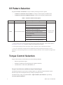
1
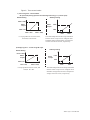
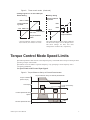
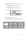
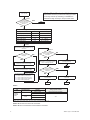
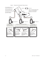
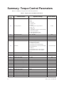
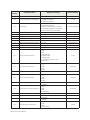
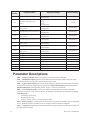
ASD TORQUE CONTROL
MANUAL
ASD Torque Control Manual
Document Number: 58696-000
Date: May, 2008
Introduction
The ASD Torque Control Manual explains the concepts behind torque control and details the relevant
parameter settings for using the Toshiba 9-Series ASD in torque control mode. Please read the entire
manual carefully before attempting to operate your ASD in torque control mode. Contact your Toshiba
sales representative for additional information.
Important Notice
The instructions contained in this manual are not intended to cover all details or variations in equipment
types. Nor may it provide for every possible contingency concerning the installation, operation, or
maintenance of this equipment. Contact your Toshiba sales representative for additional information.
The contents of this manual shall not become a part of or modify any prior or existing agreement,
commitment, or relationship. The sales contract contains the entire obligation of Toshiba International
Corporation. The warranty contained in the contract between the parties is the sole warranty of Toshiba
International Corporation and any statements contained herein do not create new warranties or modify the
existing warranty.
Any electrical or mechanical modifications to this equipment without prior written consent of
Toshiba International Corporation will void all warranties and may void other safety certifications.
Unauthorized modifications may also result in a safety hazard or equipment damage.
Misuse of this equipment could result in injury and equipment damage. In no event will Toshiba
Corporation be responsible or liable for direct, indirect, special, or consequential damage or injury
that may result from the misuse of this equipment.
Contacting Toshiba’s Customer Support
Center
Toshiba’s Customer Support Center can be contacted to obtain help in resolving any Adjustable Speed
Drive system problem that you may experience or to provide application information.
The center is open from 8 a.m. to 5 p.m. (CST), Monday through Friday. The Support Center’s toll free
number is US (800) 231-1412/Fax (713) 937-9349 — Canada (800) 527-1204.
You may also contact Toshiba by writing to:
Toshiba International Corporation
13131 West Little York Road
Houston, Texas 77041-9990
Attn: ASD Product Manager.
For further information on Toshiba’s products and services, please visit our website at
www.toshiba.com/ind/.
About This Manual
This manual was written by the Toshiba Technical Publications Group. This group is tasked with
providing technical documentation for the ASD Torque Control Manual. Every effort has been made
to provide accurate and concise information to you, our customer.
At Toshiba we’re continuously searching for better ways to meet the constantly changing needs of our
customers. E-mail your comments, questions, or concerns about this publication to
[email protected].
Manual’s Purpose and Scope
This manual provides information on how to safely implement Torque Control with the ASD. The
information provided in this manual is applicable to ASD Torque Control only.
This manual provides configuration information for controlling the ASD via Torque Control.
Because of our commitment to continuous improvement, Toshiba International Corporation reserves the
right, without prior notice, to update information, make product changes, or to discontinue any product
or service identified in this publication.
Toshiba International Corporation (TIC) shall not be liable for direct, indirect, special, or
consequential damages resulting from the use of the information contained within this manual.
TOSHIBA is a registered trademark of Toshiba Corporation. All other product or trade references
appearing in this manual are registered trademarks of their respective owners.
This manual is copyrighted. No part of this manual may be photocopied or reproduced in any form
without the prior written consent of Toshiba International Corporation.
© Copyright 2008 Toshiba International Corporation.
All rights reserved.
Printed in the U.S.A.
Table of Contents
Torque versus Speed Control ........................................................................................... 1
Torque Control Parameter Settings ................................................................................ 1
V/f Pattern Selection .................................................................................................... 2
Torque Control Selection ............................................................................................. 2
Torque Control Mode Speed Limits ................................................................................ 5
Setting Motor Constants............................................................................................... 7
Torque Control Applications............................................................................................ 9
Unidirectional Rotation ................................................................................................ 9
Bidirectional Rotation ................................................................................................ 11
Summary: Torque Control Parameters ........................................................................ 12
Parameter Descriptions .............................................................................................. 14
ASD Torque Control Manual
i
ii
ASD Torque Control Manual
Torque versus Speed Control
The Toshiba ASD can be configured to operate in either speed control or torque control mode.
Speed control mode detects variance from a reference frequency, and adjusts the ASD output frequency
and voltage to match the measured frequency to the reference frequency.
ASD
M
Speed
command
Torque control mode detects variance from a referenced motor load, and adjusts the output frequency and
voltage to match the measured load to the reference load.
Torque control of a motor is done in order to maintain a constant tension (load) on a motor. Examples
using torque control mode are accelerating/decelerating an elevator or running a winding machine.
The ASD can be set for either unidirectional or bidirectional motor rotation as required by the application.
ASD
M
Torque
command
The ASD can be configured to use either of two torque control methods:
•
Sensorless vector control relies on the internal programming of ASD.
•
Vector control with sensor requires the ASD be equipped with one of the encoder feedback options
(Toshiba Part No. VEC004Z through 007Z).
For applications requiring very accurate torque control use the vector control with sensor method. Set
parameter F015 to 8: PG Vector Feedback Control (Speed/Torque).
Torque Control Parameter Settings
Use the following parameters to configure and operate the ASD in torque control mode.
•
F015 — V/f pattern
•
F111 to F118 — Input terminal function selection (use one of them)
•
F420 — Torque command selection
ASD Torque Control Manual
1
V/f Pattern Selection
Set parameter F015 – V/f Pattern for torque control by selecting one of two options:
•
Set F015 to 4: Sensorless Vector Control if not using a motor frequency feedback sensor.
•
Set F015 to 8: PG Vector Feedback Control if using a motor frequency feedback sensor.
Table 1. Parameter F015 selection options.
Parameter
Function
Adjustment range
Default setting
0: Constant torque characteristics
1: Square reduction torque control characteristics
2: Automatic torque boost
3: Sensorless vector control (Speed)
F015
V/f control mode selection
4: Sensorless vector control (Speed/Torque)1, 3
0: Constant torque
characteristics
5: V/f 5-point setting
6: PM control
7: PG feedback vector control (Speed)
8: PG feedback vector control (Speed/Torque)1, 2
1 – Torque control (vector control) requires setting motor-related constants F014, F405 – F407 and F409. Refer to
Setting Motor Constants on pg. 7 and motor constants in the ASD instruction manual.
2 – Use two-phase input type sensor when torque control is operated in vector control with sensor mode.
3 – Use vector control with a two-phase sensor for applications requiring “forward power running ↔ reverse
regeneration,” and “forward regeneration ↔ reverse power running.” Sensorless vector control does not support these
functions.
Torque Control Selection
Torque control selection can be made by any of the following methods:
•
Discrete input terminal signal
•
Parameter commands via the EOI (Electronic Operator Interface)
•
Communication via DeviceNet, PROFIBUS, etc.
Torque Control Selection with Discrete Input Terminal Signal
This method assigns the torque control switching signal to an ASD discrete input terminal. Switch
between torque control and speed control by closing or opening the switch.
The default factory setting for parameter F117 – Input terminal 7 (S3) selection is input setting
14: Preset Speed Command 3.
2
ASD Torque Control Manual
To use S3 for control switching, change parameter F117 – Input terminal 7 (S3) selection input setting to
112: Control switching (speed/torque).
Parameter
Function
F117
Input terminal function selection 7(S3)
Note:
Adjustment range
Setting
0 to 135
112: Control switching
(speed/torque)
If the S3 terminal is already in use, assign the function to an unused discrete input
terminal.
The terminal function can be set to always-torque by setting parameter F110 – Always ON to
112: Control Switching.
Figure 1. Control Switching.
Speed Control
Torque Control
M
S3: Control Switching
S3: Control Switching
RR
RR
CCA
Control
switching
Speed
command
M
CCA
CC
OFF between S3-CC
RR-CCA (Default Setting)
Control
switching
Torque
command
CC
ON between S3-CC
RX-CCA (Default Setting)
Table 2. Command Set with F420 Enabled (Default setting: RX input).
Parameter
F420
Function
Torque command selection
Note:
Adjustment range
1: V/I (voltage/current input)
2: RR (Potentiometer/voltage input)
3: RX (voltage input)
4: Keypad input1
5: RS485 2-wire
6: RS485 4-wire
7: Communications option board
8: RX2/AI1 (differential current input)
Default setting
3: RX (voltage input)
Select 4: Keypad input to activate the control panel torque reference F725.
ASD Torque Control Manual
3
Figure 2. Three control modes.
1.) Current signal 4 – 20 mA mA DC
V/I input F108 (analog input V/I current/voltage switching) = 1 (current input)
Arbitrary Setting
Default Setting
F206 = 100%
Motor
Torque
Motor
Torque
F206
F205
F205 = 0%
4 mA
20 mA
F201 = 20%
F203 = 100%
* Torque produced: 0% at 4 mA DC,
and 100% at 20 mA DC.
F201
F203
The relationship between the torque command
and the motor torque can be changed: F201
and F203 settings 20% and 80% correspond to
currents of 8 and 16 mA DC, respectively.
2) Voltage signal 0 – 10 Vdc using RR input.
Arbitrary Setting
Default Setting
F215 = 100%
Motor
Torque
F215
Motor
Torque
F214
F214 = 0%
0V
F210 = 0%
10 V
F212 = 100%
* Torque produced: 0% at 0 V DC, and
100% at 10 V DC.
4
F210
F212
The relationship between the torque command
and the motor torque can be changed: F210
and F212 settings 20% and 70% correspond to
voltages of 2 and 7 V DC, respectively.
ASD Torque Control Manual
Figure 2.
Three control modes. (Continued)
3) Voltage signal 0 to ±10 Vdc at RX input
Arbitrary Setting
Default Setting
Torque produced
by motor
F221 = +150%
Torque produced
by motor
F221
F220
-10 V F220 = 0%
0V
F216 = 0%
-10 V
+10 V
F218 = 100%
0V
+10 V
F216 F218
Torque command
Torque command
-150%
* Torque produced: -150% at -10 V DC,
0% at 0 V DC, and 150% at 10 V DC.
The relationship between the torque command
and the motor torque can be changed: F216
and F218 settings for 20% and 80%
correspond to 2 and 8 V DC, respectively.
Torque Control Mode Speed Limits
Speed limit parameters limit the rise in the output frequency of the ASD due to a drop in load torque when
operating in torque control mode.
Speed limits can be set either at a specific frequency, or by specifying a center frequency with a
± frequency bandwidth.
Set Speed Limits with External Input Signals
Figure 3. Torque Reference Set by an External Potentiometer.
Torque reference set by an external potentiometer
Torque command
(Motor torque)
Load torque
Torque produced by
motor
Forward speed limit level
Speed
Coast Stop
Reverse speed limit level
Speed varies according to the load torque
ASD Torque Control Manual
5
Set Speed Limits with EOI (Electronic Operator Interface)
The speed limits can be set by entering the forward/reverse speed limit level parameters F426/F428.
Set Forward Speed Limit Level:
F425 – Forward Speed Limit Input selection: Set to 4: F426 setting.
F426 – Forward Speed Limit Input Level: Set desired forward speed limit level.
Set Reverse Speed Limit Level:
F427 – Reverse Speed Limit Input selection: Set to 4: F428 setting.
F428 – Reverse Speed Limit Input level: Set desired reverse speed limit level.
Figure 4. Torque Reference Set with the Operator Interface.
Forward speed limit level
F426
Speed
Coast Stop
Reverse speed limit level
F428
Speed varies according to the load torque
Set Speed Limits with External Signal
Speed limits can be adjusted by changing the selected external signals.
F425 – Forward Speed Limit Input and F427 – Reverse Speed Limit Input are used to enable/disable
setting the speed limit input with either an external discrete input or an internal preset value.
Table 3. External Signals.
Control signals
Voltage signals
Current signals
Disabled
F426/F428 Setting
6
External Input
Signal Range
F425/F427 Settings
RR-CC
0 to 10 V
2: RR
RX-CC
0 to ±10 V
3: RX
V/I-CC
0 to 10 V
1: V/I
V/I-CC
4(0) to 20 mA
1: V/I
–
–
0: Disabled
None
0.0 Hz – F012
4: F426 Setting/4: F428 Setting
ASD Torque Control Manual
Set Speed Limit using a Center Value and Limit Band
A speed limit can be set by entering the center value speed limit and speed limit band.
Table 4. Parameters for Speed Limit With the Center Value Specified by a Reference.
Parameter
Function
Adjustment range
Default setting
F430
Speed limit (torque = 0) center value
reference
0: Disabled
1: V/I (voltage/current input)
2: RR (potentiometer/voltage input)
3: RX (voltage input)
4: F431 enabled
F431
Speed limit (torque = 0) center value
0.0 Hz to F011
0.0
F432
Speed limit (torque = 0) band
0.0 Hz to F011
0.0
0: Disabled
Figure 5. Speed limit set with center value and limit band.
Speed limit
F011 – Maximum speed limit
F431 – Speed limit center value reference
F432 – ± Speed limit band
Master speed command
Speed limits can be adjusted by changing the external signals and by specifying the center reference value.
Setting Motor Constants
For greatest accuracy in torque control mode several motor parameters need to be recorded in the ASD.
These parameters can be entered manually, calculated from basic motor nameplate data, or loaded
automatically from pre-programmed Toshiba four-pole motor data.
The flow-chart on page 8 shows how to ensure the necessary parameters are recorded in the ASD memory.
ASD Torque Control Manual
7
V/f control mode
F015 = 4 or 8
Setting Motor Constants with Autotune
This flowchart shows the procedure for setting up a motor
and running autotune (if necessary) to establish the
parameters for high accuracy in torque control mode.
Note 1
Is motor
a Toshiba standard
4-pole motor with the same
capacity as the ASD?
See Note 1
YES
End
NO
Set the following parameters as specified on the motor nameplate:
Parameter
Parameter Range
Base frequency
Nameplate Information
F014
0.0 – 299.0 Hz
Base frequency voltage
F409
50.0 – 660.0 V
Rated capacity of motor
F405
0.1 – 500.0 kW
Motor rated current
F406
0.1 – 2000 A
Motor rated speed
F407
100 – 60,000 rpm
Note 2
Set F400 = 4
(After execution, the setting resets to F400 = 0)
See Note 2
Note 3
Etn 3 (Autotune Error 3)
displayed?
NO
Motor connected
and in a standby state?
See Note 3
NO
YES
YES
F014 (base frequency) or F407 (rated rotational
speed) of the motor is not set correctly.
Check the precautions to be taken when
setting F400 = 1; if not problem, then set
F400 = 2 and begin operation
Make necessary settings as specified in
(1) Setting auto-tuning
End
Enter F014 (base frequency) or F407 (rated
rotational speed) and set F400 = 4 again.
YES
Etn 1 (Autotune error 1)
or Etn 2 (Autotune error 2)
displayed?
NO
The following parameters have been calculated
and set:
F410 – Motor Constant 1 (Torque boost)
F411 – Motor Constant 2 (No-load current)
F412 – Motor Constant 3 (Leak inductance)
F413 – Motor Constant 4 (Rated slip)
F410 and F412 have been tuned to the
connected motor
F410 and F412 use the value calculated
by the ASD
End
End
Note 1:
Motor used
Type
Toshiba
standard
motor
No. Motor Poles
4-Pole
Other than
4-Pole
Tuning required: Yes/No
Capacity
Same as ASD
No (Tuned to factory defaults)*
Different than ASD
Same as ASD
Different than ASD
Yes
Others
* When using motor cables 100 ft. (30 m) or longer, set F400 (Autotune 1) = 2.
Note 2: Motor does not need to be connected.
Note 3: Motor is connected but can be loaded or unloaded.
8
ASD Torque Control Manual
Torque Control Applications
Unidirectional Rotation
If a motor rotates in one direction and does not reverse rotation during operation, set F435 – Rotation in
Specified Direction ONLY to 1: Enabled.
The direction of rotation of the motor is set by parameter F008 – Forward/Reverse Run Selection.
Set F008 to 0: Forward, or 1: Reverse, as required by the system.
See the ASD Operation Manual for details of the interaction between F008 – Forward/Reverse Run
Selection and F311 – Forward Run/Reverse Run Disable.
On a paper manufacturing line for example, once the machines have been set up the direction of rotation
of their motors is fixed and does not change.
When controlling the operation of the entire system, the torque produced in the desired direction of
rotation (direction specified by a rotation command) is considered positive torque and the torque produced
opposite of the specified rotation is considered negative torque.
In Figure 7. on pg. 10 motors ASD 1 and 2 drive rolls that rotate to send material in one direction along
the manufacturing line.
The direction of rotation of ASD 1 and 2 differ depending on whether they are placed on the top or bottom
side of the line they drive. In this case ASD 1 rotates forward, and ASD 2 rotates in reverse.
Torque commands from the host control unit of the system to the ASDs have unified polarity and the
direction of rotation of each individual motor is ignored. That is why this setting is usually used for
systems that use motors whose directions of rotation remain unchanged.
Figure 6. Unidirectional rotation: F435 – Enabled.
Forward run command enabled (F)
Reverse run command enabled (R)
Region 3
F441: Power running torque
limit
Region 1
Forward run
Region 4
Negative
torque
Positive
torque
ASD Torque Control Manual
Same torque command
Region 2
Reverse run
F441: Power running torque
limit
Positive
torque
Negative
torque
F443: Regenerative braking
torque limit
F443: Regenerative braking
torque limit
9
Figure 7. Example of Unidirectional Torque Control.
In this system the product is sent
in a fixed direction. The
direction of rotation of each
motor is determined by the
command (F or R) from the
ASD, regardless of the operating
status: power running or
regenerative braking.
Reverse run
Note: In actual practice torque
control is not necessarily
performed on all rollers.
M
M
M
ASD
ASD
ASD
1
F: Forward run
Torque control
performed by ASD 1
2
R: Reverse run
Torque control performed by ASD 2
Direction of force
Rotational direction =
Direction specified by
command = Forward run
Status: Forward/Regenerative
Region: 4
3
F: Forward run
Torque control
performed by ASD 3
Direction of force
Direction of force
10
Forward run
Rotational direction =
Direction specified by
command = Reverse run
Status: Reverse run/
Regenerative torque.
Region: 2
Direction of force
Rotational direction =
Direction specified by
command = Reverse run
Status: Reverse run/Power
running torque.
Region: 3
Rotational direction =
Direction specified by
command = Forward run
Status: Forward run/Power
running torque
Region: 1
ASD Torque Control Manual
Bidirectional Rotation
If the direction of rotation of a motor changes while the direction in which the load is applied does not, set
parameter F435 – Rotation In Specified Direction ONLY to 0 – Disabled. This disables processing of
the settings in F311 – Forward Run/ Reverse Run Disable.
Cranes and elevator motors are subjected to the kind of loading resulting in bidirectional rotation.
Figure 8. Bidirectional rotaton: F435 – Disabled.
Positive torque
Torque command
(Forward/reverse run in succession)
F441: Power running torque limit
Region 2
Region 1
Forward run
Reverse run
Region 3
Region 4
F443: Regenerative braking
torque limit
Negative torque
This setting is used for controlling a motor whose direction of rotation is determined regardless of the
forward or reverse command from the ASD.
Figure 9. Example of Bidirectional Torque Control.
In the system shown here the
direction of rotation of the motor,
its operating status, will change
between power running and
regenerative braking according to
the process demands.
ASD Torque Control Manual
Torque command > Load
torque
Rotating direction
Direction of force
Torque command < Load
torque
Rotating direction Direction of force
ASD direction specified by command
ASD direction specified by command
Rotational Direction =
Forward Run
ASD direction specified by
Command= Forward Run/
Positive Torque
(Power running)
Rotational Direction =
Reverse Run
ASD direction specified by
Command= Reverse Run/
Positive Torque
(Regenerative)
11
Summary: Torque Control Parameters
Below is a summary of torque control and related parameters.
Table 5. Torque Control and Related Parameters.
Parameter
Number
F004
12
Parameter Name
Adjustment Range
Default Setting
Frequency Mode 1
1: V/I
2: RR
3: RX
4: Not Used
5: EOI Keypad
6: RS485
7: Communications Option Board
8: RX2 (AI1)
9: Option V/I
10: UP/DOWN Frequency (terminal board)
11: Pulse Input (option)
12: Pulse Input (motor CPU)
13: Binary/BCD Input (option)
2: RR
F011
Maximum Frequency
30.0 – 299.0 Hz
80.0
F012
Upper Limit Frequency
0.0 Hz – F011
60.0
F013
Lower Limit Frequency
0.0 Hz – F012
0.0
F014
Base Frequency 1
0.0 Hz – F012
60.0
F015
V/f Pattern
0: Constant Torque
1: Voltage Decrease Curve
2: Automatic Torque Boost
3: Sensorless Vector Control (Speed)
4: Sensorless Vector Control (Speed/Torque)
5: V/f 5-Point Curve
6: PM Drive
7: PG Feedback Vector Control (Speed)
8: PG Feedback Vector Control (Speed/
Torque)
F201
V/I Input Point 1 Setting
0 – 100%
0
F203
V/I Input Point 2 Setting
0 – 100%
100
F205
V/I Input Point 1 Rate
0 – 250%
0
F206
V/I Input Point 2 Rate
0 – 250%
100
F207
Frequency Mode 2
Same as F004 (1 – 13)
F210
RR Input Point 1 Setting
0 – 100%
0
F212
RR Input Point 2 Setting
0 – 100%
100
F214
RR Input Point 1 Rate
0 – 250%
0
F215
RR Input Point 2 Rate
0 – 250%
100
F216
RX Input Point 1 Setting
±100%
0
F218
RX Input Point 2 Setting
±100%
100
F220
RX Input Point 2 Rate
±250%
0
F221
RX Input Point 2 Rate
±250%
100
F222
RX2 Input Point 1 Setting
±100%
0
F224
RX2 Input Point 2 Setting
±100%
100
F226
RX2 Input Point 2 Rate
±250%
0.0
0: Constant Torque
1
ASD Torque Control Manual
Parameter
Number
F227
Parameter Name
Adjustment Range
Default Setting
RX2 Input Point 2 Rate
±250%
Forward Run/Reverse Run Disable
0: Off
1: Disable Reverse Run
2: Disable Forward Run
F400
Autotuning 1
0: Autotune Disabled
1: Reset Motor Defaults
2: Enable Autotune on Run Command
3: Autotuning by Input Terminal Signal
4: Motor Constant Auto-calculation
F405
Motor Rated Capacity
0.1 – 500.0 hp
F406
Motor Rated Current
0.1 – 2000.0 A
20.3
F407
Motor Rated RPM
100 – 60,000 RPM
1730
F409
Base Frequency Voltage 1
50.0 – 660.0 V
ASD Dependant
F410
Motor Constant 1 (Torque Boost)
0.0 – 30.0%
ASD Dependant
F411
Motor Constant2 (No-load Current)
10 – 90%
ASD Dependant
F412
Motor Constant3 (Leak Inductance)
0 – 200%
ASD Dependant
F413
Motor Constant 4 (Rated Slip)
0.01 – 25.00%
ASD Dependant
Torque Command Selection
1: V/I
2: RR
3: RX
4: Panel Keypad
5: RD482 2-Wire
6: RS482 4-Wire
7: Communication Option board
8: RX2 (AI1)
F425
Forward Speed Limit Input
0: Disabled
1: V/I
2: RR
3: RX
4: F426
F426
Forward Speed Limit Level
0.0 Hz – F012
F427
Reverse Speed Limit Input
0: Disabled
1: V/I
2: RR
3: RX
4: F426
F428
Reverse Speed Limit Level
0.0 Hz – F012
80.0
F430
Speed Limit Center Value Reference
0: Disabled
1: V/I
2: RR
3: RX
4: F431Setting
0: Disabled
F431
Speed Limit Center Value
0.0 Hz – F011
0.0
F432
Speed Limit Band
0.0 Hz – F011
0.0
F435
Rotation in Specified Direction Only
0: Disabled
1: Enabled
Power Running Torque Limit 1
1: V/I
2: RR
3: RX
4: F441 Setting
F311
F420
F440
ASD Torque Control Manual
100
0: Off
0: Autotune Disabled
11.0
3: RX
0: Disabled
80.0
0: Disabled
0: Disabled
4: F441
13
Parameter
Number
Parameter Name
F441
Power Running Torque Limit 1 Level
0.0 – 249.9%
250 (Disabled)
250 (Disabled)
F442
Regenerative Braking Torque
Limit 1
1: V/I
2: RR
3: RX
4: F443 Setting
4: F443
F443
Regenerative Braking Torque
Limit 1 Level
0.0 – 249.9%
250 (Disabled)
250 (Disabled)
F444
Power Running Torque Limit 2 Level
0.0 – 249.9%
250 (Disabled)
250 (Disabled)
F445
Regenerative Braking Torque
Limit 2 Level
0.0 – 249.9%
250 (Disabled)
250 (Disabled)
F446
Power Running Torque Limit 3 Level
0.0 – 249.9%
250 (Disabled)
250 (Disabled)
F447
Regenerative Braking Torque
Limit 3 Level
0.0 – 249.9%
250 (Disabled)
250 (Disabled)
F448
Power Running Torque Limit 4 Level
0.0 – 249.9%
250 (Disabled)
250 (Disabled)
F449
Regenerative Braking Torque
Limit 4 Level
0.0 – 249.9%
250 (Disabled)
250 (Disabled)
F472
RR Input Bias
0 – 255
F473
RR Input Gain
0 – 255
154
F474
RX Input Bias
0 – 255
127
F475
RX Input Gain
0 – 255
127
F476
RX2 Input Bias
0 – 255
128
F477
RX2 Input Gain
0 – 255
128
F725
Panel Torque Command
±250%
0.00
F727
Panel Tension Torque Bias
±250%
0.00
Adjustment Range
Default Setting
128
Parameter Descriptions
F004 — Frequency Mode 1 specifies the input source for the frequency command.
F011 — Maximum Frequency specifies the absolute maximum frequency that the ASD will output.
Acceleration/deceleration times are calculated based on this value.
F012 — Upper Limit Frequency specifies the highest frequency that the ASD will accept as a frequency
command. The ASD may output frequencies higher than Upper Limit Frequency (but no higher than
Maximum Frequency) when operating in PID-, Torque-, or Vector Control mode.
F013 — Lower Limit Frequency is the lowest frequency that the ASD will accept as a frequency
command or set point. Under certain conditions the ASD may output frequencies lower than the Lower
Limit Frequency.
•
•
•
Accelerating from a stop,
Decelerating to a stop,
System is in PID-, Torque-, or Vector Control modes
F014 — Base Frequency 1 is the frequency at which the output voltage of the ASD reaches its maximum
setting. The Base Frequency should be set to the frequency listed on the motor nameplate.
F015 — V/f Pattern establishes the relationship between the output frequency and the output voltage. See
the ASD manual for details.
14
ASD Torque Control Manual
F201, F203 — V/I Input Point 1, 2 Setting sets two points that establish the V/I response slope. The two
points typically refer to the lower and upper range limits as a percent of maximum frequency/full-load
torque. The use of F201, F203, F205, and F206 is explained in detail in the ASD Operation Manual.
F205, F206 — V/I Input Point 1, 2 Rate is used to set the gain and bias of the V/I input terminal when
operating in Torque Control Mode. These parameters set the output torque value associated with Input
Point Settings as a percent of full-load torque.
F207 — Frequency Mode 2 specifies the input source for the frequency command used as Frequency
Mode 2.
F210, F212 — RR Input Point 1, 2 Setting set the two points that establish the RR response slope. These
two settings are entered as a percentage of F011– Maximum Frequency. The use of F210, F212, F214,
and F215 is explained in detail in the ASD Operation Manual.
F214, F215 — RR Input Point 1, 2 Rate is used to set the gain and bias of the RR input terminal when
operating in Torque Control Mode. These parameters set the output torque value associated with Input
Point Settings as a percent of full-load torque.
F216, F218 — RX Input Point 1, 2 Setting set the two points that establish the RX response slope. These
two settings are entered as a percentage of F011– Maximum Frequency. The use of F216, F218, F220,
and F221 is explained in detail in the ASD Operation Manual.
F220, F221 — RX Input Point 1, 2 Rate is used to set the gain and bias of the RX input terminal when
operating in Torque Control Mode. These parameters set the output torque value associated with Input
Point Settings as a percent of full-load torque.
F222, F224 — RX2 Input Point 1, 2 Setting set the two points that establish the RX2 response slope.
These two settings are entered as a percentage of F011– Maximum Frequency. The use of F222, F224,
F226, and F227 is explained in detail in the ASD Operation Manual.
F226, F227 — RX2 Input Point 1, 2 Rate is used to set the gain and bias of the RX2 input terminal when
operating in Torque Control Mode. These parameters set the output torque value associated with Input
Point Settings as a percent of full-load torque.
F311 — Forward Run/Reverse Run Disable sets the Forward Run or Reverse Run mode. If 0 – Off is
selected the received direction command will determine the motor rotation.
F400 — Autotuning 1 sets the autotune command status. See the ASD User Manual for details.
F405 — Motor Rated Capacity sets the nameplate rated capacity.
F406 — Motor Rated Current sets the nameplate rated current.
F407 — Motor Rated RPM sets the nameplate rated motor speed.
F409 — Base Frequency Voltage 1 is the motor output voltage at F014 – Base Frequency 1.
F410 — Motor Constant 1 (Torque Boost) sets the primary resistance of the motor. Increasing this value
can prevent a drop in motor torque at low speeds.
F411 — Motor Constant 2 (No-load Current) specifies the current lever required to excite the motor.
Specifying a value that is too high may result in erratic motor operation.
F412 — Motor Constant 3 (Leak Inductance) sets the leakage inductance of the motor. A higher setting
results in a higher output torque at high speeds.
F413 — Motor Constant 4 (Rated Slip) sets the secondary resistance of the motor. An increase in this
parameter results in an increase in compensation for motor slip.
F420 — Torque Command Selection in Torque Control mode allows the user to select the source of the
torque command signal.
F425, F427 — Forward, Reverse Speed Limit Input enables/disables the Forward/Reverse Speed
Limit Input control function. When enabled in Torque Control mode, the forward/reverse speed limit is
controlled by the selected input.
F426, F428 — Forward, Reverse Speed Limit Input Level provides a set value to used as the forward/
reverse speed limit settings if Setting is selected in F425 or F427.
ASD Torque Control Manual
15
F430 — Speed Limit Center Value Reference selects the input terminal that be used to control the
allowable speed variance.
F431 — Speed Limit Center Value sets the target speed in Torque Control mode.
F432 — Speed Limit Band establish a plus-or-minus bandwidth for the corresponding Speed Limit
Center Value in F431.
F435 — Rotation in Specified Direction Only enables or disables the Forward Run or Reverse Run
mode. If either direction is disabled, commands for the disabled direction will not be recognized.
F440 — Power Running Torque Limit 1 determines the source of the control signal for the positive
torque limit settings. If Settings is selected, the value set in F441 is used as the input.
F441, F444, F446, F448 — Power Running Torque Limit 1 – 4 Level provides the value of the control
signal input for the positive torque upper limit for the #1 – #4 motor profiles if Settings is selected.
F442 — Regenerative Braking Torque Limit 1 determines the source of the control signal for the
Regenerative Torque Limit settings. If Settings is selected, the value set in F443 is used as the input.
F443, F445, F447, F449 — Regenerative Braking Torque Limit 1 – 4 Level provides the value of the
control signal input for the Regenerative Torque Limit for the #1 – #4 motor profiles if Settings is
selected.
F472, F474, F476 — RR/RX/RX2 Input Bias may be used to ensure that the zero level of the input
source is also the zero level setting of the ASD system.
F473, F475, F477 — RR/RX/RX2 Input Gain may be used to fine tune the gain of the input terminal to
ensure that the 100% level of the input source is also the 100% level of the ASD system.
F725 — Panel Torque Command sets the torque command when using the LED Keypad option.
F727 — Panel Tension Torque Bias sets the torque bias when using the LED Keypad option.
16
ASD Torque Control Manual
ASD Torque Control Manual
17
INDUSTRIAL DIVISION
13131 West Little York Road, Houston, Texas 77041
Tel 713/466-0277 Fax 713/937-9349
US 800/231-1412 Canada 800/872-2192 Mexico 01/800/527-1204
www.toshiba.com/ind
Printed in the U.S.A.