1
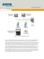
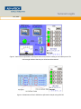
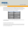
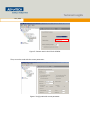
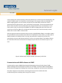
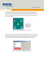
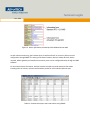
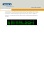
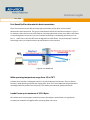
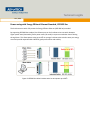
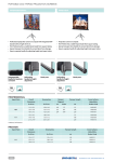
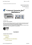
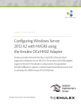
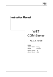
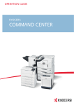
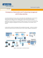
Technical Insights Nov, 2014 Convergence of Automation and IT networking management with ProView Switches In a modern industrial environment, sensors, control nodes, PLCs and SCADA servers are connected via switches and wireless Apps, to create a complex network. As the number of devices increase, management and issue diagnostics are a challenging job for both IT and automation professionals. As a global leader of industrial networking, Advantech introduces the world’s very first series of switches that will lead the convergence management in the worlds of IT and automation: The “ProView” series of switches. ProView switches combine the advantages of both managed and unmanaged switches to introduce a simple and cost effective solution with information for central network management and diagnostics. Figure 1. ProView Switch in an Industrial network Technical Insights Nov, 2014 In order to allow both automation software and IT software to monitor the switch status, the ProView series switches support both Modbus/TCP and SNMP protocols. This allows SCADA software such as Wonderware InTouch, Advantech WebAccess, WinCC, iFix, and IT Network Management System (NMS) software such as SNMPc and OpenNMS to monitor the switch device status in real time. The devices come with Port-based QoS for deterministic data transmission that allows data from the VIP port to have a higher priority compared to data from a normal port. ProView switches use the highest quality components, to achieve a wide range of operating temperature from -40 to 75°C along with Level 3 EMS protection from electromagnetic interference. System Highlight Communication with HMI / SCADA software via Modbus/TCP. Communication with NMS (Networking management system) via SNMP. Port-based QoS for deterministic data transmission. Wide Operating temperature range from -40 to 70°C. EMS level 3 protection for extreme outdoor environments. Power saving with Energy Efficient Ethernet Standard, IEEE 802.3az. Jumbo Frames up to maximum of 9,216 Byte. Power source redundancy with two 12~48V DC power inputs and P-Fail relay. Loop detection. Communication with HMI/ SCADA software via Modbus/TCP The Modbus/TCP protocol has been built into Advantech ProView switches which allow a majority of popular SCADA system such as InTouch, InduSoft, WinCC and iFIX to obtain device status and information. This allows all devices, including ProView switches and I/O control devices, to be controlled and monitored through one HMI/SCADA system. In the following SCADA software example, by using InTouch from Wonderware, we connect the SCADA server (TPC-651H), one analog I/O Modbus TCP module (ADAM-6017) and one digital I/O Modbus TCP module (ADA-6050) to the ProView switch (EKI-5526). The topology is shown below: Technical Insights Nov, 2014 Figure 2. Typical Industrial Application Topology We use the SCADA software to access the memory address in the ProView Switch through Modbus/TCP. This allows us to obtain the device information such as the device name, FW version, MAC and IP address, and also the port status information such as port link up/down, link up counter and port speed. This information further helps the engineer diagnose any issue. When a signal is lost by the end device, by having both the network information and the device information displayed on the SCADA, we are able to conclude that the signal lost is caused by either the network or the end device itself. For example, in figures 2 and 3 below, by reading the status of port 4 at memory location 34100 on the ProView switch through Modbus/TCP; we are able to know that the port has been disconnected and combined with SCADA HMI, the status indicator of port 4 turns red. This allows on-site engineers to easily identify that the lost signal is caused by a disconnected network cable or by malfunction of the voltmeter or the Modbus TCP module. This helps to quickly narrow down the root cause of an issue. Technical Insights Nov, 2014 Figure 3. Switch device information, switch port status and I/O device reading in one SCADA system. The red rectangle indicates that the port 4 has been disconnected. Figure 4. Wonderware InTouch SCADA Port Information Sample using EKI-5726 Technical Insights Nov, 2014 As well as basic device information and the port link up/down status, the ProView switch provides detailed statistical port information on each port including speed, linkup counter, count on the multicast packet, count on unicast packet and count on error. This allows engineers to observe the network status and statistic in detail from any HMI / SCADA software which supports Modbus/ TCP. The detailed information provided by the ProView switch is listed in the table below. System Info Vendor ID Port Status Port Status Unit ID Port Speed Product Code Flow Control Vendor Name Port Description Product Name Link Up Counter FW Version Tx Packets Counter Ethernet MAC address Rx Packets Counter IP Address Table 1: Modbus Information table In a HMI / SCADA system such as InTouch, address mapping and Modbus/TCP connection is the initial step to setup the InTouch. Using ProView switch with Wonderware InTouch For InTouch being able to connect to the ProView switch, we need to have the InTouch know where our ProView switch is on the network. Thus, we first need to create a new node with an IP of the ProView switch in the System Management Console. Technical Insights Nov, 2014 Figure 5. Create a node in the InTouch SCHADA Then, we set the node with the correct parameters. Figure 6. Config node with correct parameter. Technical Insights Nov, 2014 Next we add one device, “ProVewSW” in the device group with a suitable update interval time; in this case we chose 1000 ms. Figure 7. Add the device in device groups and set update interval. After the connection setting is finished, right-click on the node and select “activate the server” to start the server. Another initial configuration is the tags. Tags have been used in InTouch as the points of data. Tags can be defined and modified by using the Tagname dictionary. InTouch needs tags, which are points of data and uses the Tagname dictionary to define these data points. You can modify or create new tags using the Tagname dictionary. Figure 8. Tagname Dictionary. Technical Insights Nov, 2014 In this example, we created a new tag to obtain the Ethernet port 1 status from the ProView switch. We created “Port001_Status” as the tag name, and I/O Integer as the tag type. Refer to the Modbus TCP address mapping table in the user manual, we know the port status data stored on the switch is represented by four HEX characters, which is 65,536 bits in data length. Thus we entered Min EU and Max EU from 0 to 65535. Then we selected the pre-configured device name “ProViewDemo” as the access name. Finally, we referred to the Modbus TCP address mapping table that comes with user manual, we can find the address for the Ethernet Port 01 status data is stored at memory location, 34097, thus we enter 34097 in the item field. After the tag and connection have been setup correctly, the HMI/SCADA software is now able to obtain the specific data from the ProView switch. With minor modification to the interface, you will be able to display the data on the SCADA screen in the way you preferred. For example you can have the connected port in green and disconnected port in red as in the example below. The SCADA will obtain the information from the ProView switch and display the port status for all 16 Ethernet ports in real time. Figure 9. SCADA display interface example, port status for EKI-5526. Communication with NMS software via SNMP ProView switches support SNMP (Simple Network Management Protocol) which allows IT NMS (Network Management System/Station) software such as SNMPc, SusuAccess NMS and OpenNMS to perform device management including status monitoring, configuration and even events notification. This allow IT engineers to have better monitoring and control on the network and easier troubleshooting when something went wrong on the network. Technical Insights Nov, 2014 In an industrial environment such as manufacturing, nothing is more important than keeping the network, which is formed by thousands of sensor devices, running smoothly without any downtime. SNMP has been widely used by engineers to monitor the network device status and an NMS is able to provide an intuitive network topology with a real time device status similar to the topology example shown in Figure 10 below. Figure 10. Network Management System using SNMPc For information that is not supported by a standard SNMP MIB library, Advantech provides a private MIB file that allow NMS software have the method of obtaining this information. To add a private MIB into your NMS software, we need to compile the Advantech private MIB file into the library as the example using SNMPc shown in figures 11 and 12 for private and public device information. Figure 11. Add Private MIB into MIB library of NMS software Technical Insights Nov, 2014 Figure 12. Device information provided by Public MIB and Private MIB As well as device monitoring, the ProView series of switches allow IT to control or perform certain configuration through SNMP. The setting of the device location, device IP mode, device IP, device netmask, default gateway and read/write community name can be configured directly through the NMS software. For the statistical port information, ProView switches are able to provide statistical information including count on unicast, multicast and broadcast packet for each individual Ethernet port. Table 13. ProView Switch port status and statistic using SNMPc Technical Insights Nov, 2014 ProView switches support SNMP traps which will automatically notify the SNMP server when there are events such as port link-down/up, cold start and warm start occurs. This information allows IT engineers to be notified of a network status change, not just on the ProView switch, but also on the devices connected to it, imminently and act quickly. In figure 14 below, it shows the trap message example in the SNMPc. Figure 14. ProView Switch send out SNMP trap to server to notify the server the occurrence of events. Technical Insights Nov, 2014 For the complete SNMP function list, refer to table 3 below. MIB File Name system: sysDescr sysObjectID sysLocation sysContact SysName interface: ifNumber ifTable ifIndex ifDescr RFC1213 ifSpeed ifOperStatus ifInOctets ifInUcastPkts ifInNUcastPkts ifInDiscards ifInError ifOutOctets ifOutUcastPkts ifOutNUcastPkts ifOutDiscards ifOutErrors snmpMIB: SNMPv2 snmpTraps coldStart warmStart MIB File Name ifMIBObjects: ifXTable ifName ifInMulticastPkts ifInBroadcastPkts ifOutMulticastPkts ifOutBroadcastPkts ifHCInOctets ifHCInUcastPkts ifMIB ifHCInMulticastPkts ifHCInBroadcastPkts ifHCOutOctets ifHCOutUcastPkts ifHCOutMulticastPkts ifHCOutBroadcastPkts snmpTraps LinkDown LinkUp system: sysModelID sysImageVersion ipAddress: ipMode ipAddress Advantech netmask ProView defaultGW MIB etherAddress: etherAddr snmpConf: snmpVersion readCommunity writeCommunity trapServerIpaddr Table 3. SNMP MIB table Technical Insights Nov, 2014 Port-Based QoS for deterministic data transmission There are a maximum of two VIP ports with high transmission priority which can be used for deterministic data transmission. The priority ratio between the VIP port and the normal port is 1.5 to 1. For example, when there are two traffic flows on a ProView switch at the same time. When traffic flow 1 is transmitting data from VIP port 1 to port 5 and also traffic flow 2 is forwarding data from port 3 to port 5, traffic flow 1 can have 50% more throughput than traffic flow 2. The port base QoS is useful to ensure high priority on important data to be transmitted in a busy network. Figure 8. Port Based QoS Wide operating temperature range from -40 to 70°C ProView series switches are designed to work in any harsh industrial environment. They are able to function in wide operating temperatures ranging from -40 to 70°C. These wide operating temperature unmanaged switches provide rock-solid, worry-free stability and industrial-grade performance. Jumbo Frame up to maximum of 9,216 Bytes All ProView series switch support jumbo frames up to 9,216 bytes. Jumbo frames can significantly increase your network’s throughput while consuming fewer CPU cycles. Technical Insights Nov, 2014 Power saving with Energy Efficient Ethernet Standard, IEEE 802.3az The ProView series switch fully meets the Energy-Efficient Ethernet (IEEE 802.3az) standard. By supporting IEEE 802.3az standard, the Ethernet port on the ProView series can switch between higher power state (data mode) /lower power state (LPI mode) in response to whether data is flowing through them. This allows power saving up to 60% in average, ProView series switches saves you energy costs and provide unquestionable industrial-grade performance and stability. Figure 9. IEEE802.3az allow ProView switch to save power up to 60%. Technical Insights Nov, 2014 Loop Detection All ProView switches come with built-in loop detection and LED indicator. This can help prevent careless network deployment. During a complex network deployment, system installation staff may accidentally connect the device with the wrong cable and cause a loop back on the network which can eventually create a broadcast storm and in the worst case, melt the network. Figure 10.Loop Detection LED for easy diagnostic. On the ProView switch, in the case of a loop detection, the “Loop Detection” LED indicator on the device switch will instantly light to notify the installer and remove the connection just installed. Conclusion With the communication capability using both Modbus/TCP and SNMP protocol, the ProView series of switches are the very first networking switches in the world that provides management convergence between industrial control and IT networking management. The ProView series of switches are positioned in between unmanaged and managed switch to introduce a simple and cost effective solution for increasingly complex industrial networking.