1
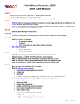
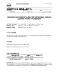
FlexClock® Z18
USER MANUAL & SETUP GUIDE
FLEXCLOCK SERIES
M U L T I - P U R P O S1E T I M E D E V I C E
Table of Contents
Overview ............................................................................... Page 3
Quick Setup .......................................................................... Page 4
Installation ............................................................................ Page 5
Network Setup .................................................................... Page 8
Clock Setup and Use.......................................................... Page 10
Troubleshooting ................................................................. Page 11
Clock Dimensions
L: 5.25 in ; W: 7.25 in ; D: 2.25 in
2
Getting Started
The FlexClock Z18 is an Ethernet-based time clock with an integrated proximity badge reader. The punch data collected at the clock is transmitted over the
Internet to the timekeeping server and is available online nearly instantly.
The Z18 is a versatile time clock that supports a variety of additional options
(sold separately), including: a bell system; an add-on biometric device (fingerprint reader); and a third-party proximity badge reader for existing building
proximity or security systems.
Punch Data Collection
The Z18 will collect employee punches in two ways, either through a proximity badge card (assigned to an employee) or an employee PIN (Personal
Identification Number). If using SSN only is desired, the option may need to
be activated by your service provider. The PIN option can be helpful if a new
employee does not yet have a proximity badge assigned or their badge is
temporarily unavailable.
Connectivity
The Z18 transmits employee punch data through an Ethernet Internet
connection. This is also commonly referred to as a “digital,” Internet-based,
or IP-based connection. Punches are sent continuously throughout the day
as employees punch IN/OUT to allow for immediate supervisory editing and
reporting. To minimize the time spent by employees at the clock, employees
can punch IN/OUT even while punches are being transmitted in the “background” to the timekeeping server.
3
Quick Setup
The basic installation process involves wall mounting the clock, connecting
it to the network and inserting the clock’s power supply. Detailed installation
information can be found in the following pages of this manual. The basic
installation steps are:
1. Use the included mounting template to mark the locations of the mounting
screws and where the wires will pass through the wall to the back of the clock.
2. Run the low voltage power and Ethernet cables in the wall to where the
clock will be installed.
3. Mount the clock’s backplate to the wall.
4. Connect the basic wire harnesses (power and Ethernet) to the clock.
5. Connect the power and Ethernet cables to the clock’s wire harnesses.
6. Hang the clock on the backplate and secure it with the Torx screw at the
bottom of the clock.
8. Have your network administrator open TCP ports 8288 and 8289 on the
network firewall for outbound connections.
9. Configure the clock to reach the Internet. The clock can be configured
automatically using DHCP. If it doesn’t, or if that is not desired, the clock can
be configured manually. To do this, on the clock keypad: press (MENU) twice;
type the number “2663” then (OK); press (1); follow the clock menus to
manually enter the network configuration information.
10. The clock will attempt to contact the timekeeping server whenever a
punch is made or when the (9) key is pressed on the clock’s keypad.
11. Once the clock has completed the initial connection with the timekeeping
server, it is ready to use.
12. Employees will need to press (1) to punch IN or press (2) to punch OUT,
then waive their badge in front of the clock.
4
Installation
The Z18 is designed to be permanently mounted, with all the wires and
connections concealed in the wall behind the clock. As such, the Z18
typically requires professional-level installation by an electrician or
qualified technician.
Caution: Damage to the clock due to improper installation will void the
warranty.
Tools and Supplies
Installation of this clock may require some or all of the following tools and
items:
• Electrical tape and/or wire ties
• Wire cutter/stripper/crimper
• Philip’s Screwdriver
• Knife or drywall saw
• Wire pulling tools
The following items are included and packaged with the clock:
• FleckClock Z18
• 12 volt DC Power supply
•Backplate
• Backplate pad
• Mounting template
• Basic installation materials kit:
• T10 Torx screwdriver
• Drywall anchors
• Crimp style wire connectors
• Ethernet harness
• Power harness
• Advanced setup kit
5
Installation
Mounting The Backplate
The clock comes with simple screw-in style drywall anchors, though ideally,
the backplate should be screwed firmly into a stud or some type of sturdy
backing.
A mounting template is provided to mark the location of the wall anchors and
the small section of the wall that needs to be cut out for the cables to pass
through.
The clock comes shipped with a metal backplate attached. Remove the screw
from the bottom of the clock with the included Torx screwdriver and separate
the backplate from the clock. The backplate must be mounted to the wall
while separated from the clock. The included rubber pad should be placed
between the backplate and the wall.
Wiring The Clock
In order for your clock to function, low voltage power and an Ethernet
connection are required inside the wall where the clock will be installed. The
2-pin connector for power and 4-pin connector for Ethernet can be found in
the Basic Installation Kit.
The power wire harness has a 2-pin connector that plugs into the clock and a
standard “barrel” style power connector on the other end. The included power
supply plugs directly into the barrel end of this harness.
6
Installation
If necessary, the power cable can be extended with low-voltage wire (such as
18-gauge speaker wire) to a convenient or hidden power outlet. Care must be
taken to ensure proper polarity in order to prevent damage to the clock. The
power supply connector is wired with a positive center. If power is connected
with reversed polarity, the clock will be damaged. Damage due to improper
installation will not be covered under warranty.
The Ethernet wire harness has a 4-pin connector that plugs into the clock and
a convenient RJ45 jack on the other end that accepts a standard Ethernet
cable.
Additional wire harnesses can be found in the Advanced Installation Kit. These
wiring harnesses are only necessary if the following will be attached: bell
system; external proximity card reader; external fingerprint reader; or external
barcode or magnetic stripe card reader.
If any of these wire harnesses are attached during installation, each unused
wire end should be taped off separately to prevent damage to the clock
through short circuits. It is vital that the wiring harnesses attached to the
clock are protected from being tugged out by accident.
Note: If it is not desirable to run cabling through the wall, an option that may
be considered is to mount the clock onto a cabinet or furnishing that would
allow access to the back of the clock for making connections and running
cables.
Hanging The Clock
The clock hangs on the backplate in a somewhat reversed fashion. Rather
than “hanging” on the mounting posts and sliding downward, the clock must
be positioned onto the backplate’s mounting posts and then pushed upward.
Once the clock is pushed into its final position, the Torx screw on the bottom
of the clock can be installed to secure the clock to the backplate.
7
Network Setup
Once the clock has been “plugged in” to a network, it must be configured
before it will communicate properly. If the network is DHCP enabled, the clock
will be configured automatically once it is powered on. Alternatively, the clock
can be configured manually with information obtained from the network
administrator.
For the purpose of setting up this Z18, in simple terms, a network router
allows a device (the clock) on a private network to send and receive data over
the Internet, while a firewall secures the private network against unauthorized
or dangerous connections.
Firewall Information
Sometimes the network firewall must be specifically set up to allow the Z18 to
initiate connections to the timekeeping server. In the event of a clock connection problem, contact the Network Administrator and have them make
changes to the firewall to allow outbound connections through TCP ports
8288 and 8289. Even if no connection problems exist initially, it is recommended that these ports are specifically opened in the firewall to prevent
future issues.
Although rare, some networks will also restrict unknown IP addresses. If needed, the IP addresses of the timekeeping servers are: 208.72.167.2 (primary
server), and 166.70.147.9 (secondary server).
Note: The Z18 will only make outgoing connections. All communications with
the timekeeping servers are done through connections initiated by the Z18
from inside the network.
Manual Network Configuration
This section details the process of manually configuring the Z18 to work on
the attached network. Only use this section if the clock can not obtain the
network configuration automatically (DHCP is not available), or if setting up
the clock with a static IP address is preferable. In order to configure the clock
manually, the following information will need to be provided by the Network
Administrator: static IP address; subnet mask; and default gateway.
8
Network Setup
The network configuration can be viewed or changed from the “TCP/IP
Options” menu. Follow the steps below to access the TCP/ IP Options menu
from the main “Time” and “Date” screen:
1. On the keypad press (MENU) twice to access the
“System Info” screen.
2. Type the number “2663” and then press (OK) to access the
“Network Setup” menu.
3. Press (1) to access the TCP/IP Options menu.
Once in the TCP/ IP Options menu the screen will display whether the clock is
currently set up with DHCP or a static IP. This menu has the following options:
[1] to show the current network configuration settings.
[2] to change the network configuration settings.
[3] to enable DHCP (Only available if the clock is configured with
a static IP).
The Change Settings option in the Network Setup menu (see instructions
below). When typing the IP addresses in the clock, type periods (.) using the
(MENU) key.
Note: The current static IP settings will be lost whenever DHCP is enabled.
Writing down the current settings before making any changes is recommended.
9
Other FlexClock Models
The FlexClock Z-Series
Provides Ethernet connectivity and available biometrics at an unbeatable
value.
· FlexClock Z18 is a simple and affordable time clock using
a proximity card reader.
· FlexClock Z33 and Z34 are simple and affordable time clocks
with a built-in fingerprint reader. (They function the same,
differing only in style and appearance).
The FlexClock Vx-Series
Based on quality banking equipment from VeriFone®. All Vx-Series clocks
include a magstripe card reader, receipt printer, and fully support analog
dialup (landline) as an alternate communication method. Options include:
· FlexClock Vx510 and Vx570 - Basic model with Ethernet, Dialup,
and a printer. The Vx570 can be wall mounted while the Vx510 is
meant for tabletop use only.
· FlexClock Vx510G - Offers a cellular connection instead of
Ethernet. Requires AC power or vehicle power.
· FlexClock Vx610 - Offers a cellular connection instead of Ethernet,
and is completely portable with a built-in rechargeable battery.
Optional external fingerprint accessory available for all FlexClock
Vx-Series models.
Additional Questions
If you have any additional questions regarding the installation or use of your
FlexClock, please contact your service provider.
10
11
FlexClock Z18 Setup Guide
The company distributing this product does
not accept liability or responsibility for inaccurate
or missing information within this manual.
Any and all content within this document is
subject to change and may be updated at any
time without notice.
Copyright 2014
12
Printed in the USA 0601C