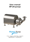
1
User manual CPC Centrifugal pumps Pomac bv - Feithspark 13 - 9356 BX Tolbert - the Netherlands Tel +31(0) 594 512877 - Fax +31(0) 594 517002 info@ pomacpumps.com - www.pomacpumps.com This user manual has been released d.d.:................................ and belongs to: CPC Pump serial number 3 capacity m /h pressure bar NPSHR m Drive, make type speed voltage min / / V frequency Hz current A power kW isolation class protection class area classification Coupling, make type size IP -1 User manual Pomac CPC pumps User manual Pomac CPC pumps This manual has been compiled with the utmost care. However, POMAC assumes no liability for possible deficiencies of the information in this manual. It is the responsibility of the buyer/user of this pump to ensure this information is complete and up-to-date. All technical information mentioned in this user manual remains property of Pomac bv and may only be used for the installation, operation and maintenance of this pump. The information may not be copied, duplicated or passed on to third parties without our written permission. Copyright 2012 Pomac bv Release date: April 2012 Doc. ID. : CE/CPC (1204) EN-01 CE/CPC (1204) EN-01 1 User manual Pomac CPC pumps DECLARATION OF INCORPORATION (according to Annex II 1 B of the Machinery Directive (2006/42/EC – 1st Edition – December 2009) Pomac bv Feithspark 13 9356 BX Tolbert The Netherlands hereby declares completely under own responsibility that the pumps mentioned below: Model: Types: Execution: Materials: Centrifugal pump CPC KAM, KAV, KAC, IG, IGH 1.4404 (AISI 316L) or 1.4435 or 2.4602 (Hastelloy C22) to which this declaration refers to, are in conformity with the following standards: Standards: EN-ISO 12100 parts 1 & 2 NEN-EN 60204 part 1 EN 809 The pump must not be put into service until the final machinery into which it is to be incorporated has been declared in conformity with the provisions of this Directive (2006/42/EC), where appropriate. Issued at Tolbert, 2 nd of April 2012 H. Poelstra Managing Director 2 CE/CPC (1204) EN-01 User manual Pomac CPC pumps Table of contents 1. Introduction ....................................................................................................................................... 5 1.1. General information................................................................................................................... 5 1.2. Warranty .................................................................................................................................... 5 1.3. Transport and receipt ................................................................................................................ 5 1.4. Pump identification .................................................................................................................... 6 1.5. Type code ................................................................................................................................. 7 1.6. Ordering spare parts ................................................................................................................. 8 1.7. Manufacturer ............................................................................................................................. 8 2. Safety ............................................................................................................................................... 9 2.1. General information................................................................................................................... 9 2.2. Instructions ................................................................................................................................ 9 2.3. Staff ........................................................................................................................................... 9 2.4. Precautions ............................................................................................................................. 10 2.5. Changed application ............................................................................................................... 10 3. Description CPC centrifugal pump ................................................................................................. 11 3.1. Pump description .................................................................................................................... 11 3.2. Certification ............................................................................................................................. 11 3.3. Application area ...................................................................................................................... 11 3.4. Pump impeller design.............................................................................................................. 11 3.5. Type description ...................................................................................................................... 11 3.6. Connections ............................................................................................................................ 11 3.7. Materials .................................................................................................................................. 11 3.8. Construction variants .............................................................................................................. 12 3.9. Shaft seals .............................................................................................................................. 13 3.9.1. Materials .......................................................................................................................... 13 3.9.2. Type indication code ........................................................................................................ 13 3.9.3. Explanation double action mechanical seals ................................................................... 13 3.10. Drive .................................................................................................................................... 13 4. Installation ...................................................................................................................................... 14 4.1. General.................................................................................................................................... 14 4.2. Assembling Type IG ................................................................................................................ 14 4.3. Connecting the electric motor ................................................................................................. 14 5. Putting into operation ..................................................................................................................... 15 5.1. Precautions ............................................................................................................................. 15 5.1.1. General ............................................................................................................................ 15 5.1.2. Quench ............................................................................................................................ 15 5.1.3. Flush ................................................................................................................................ 15 5.2. Checking the rotation direction ............................................................................................... 15 5.3. Putting into operation .............................................................................................................. 15 5.4. In operation ............................................................................................................................. 16 5.4.1. Noise ................................................................................................................................ 16 5.4.2. Daily maintenance ........................................................................................................... 16 5.4.3. Cleaning procedure and agents ....................................................................................... 16 5.4.4. Periodic maintenance ...................................................................................................... 16 5.5. Malfunction .............................................................................................................................. 17 6. Overhaul and repair ........................................................................................................................ 18 6.1. Removing the pump ................................................................................................................ 18 6.2. Dismantling and assembling the pump ................................................................................... 18 6.2.1. Dismantling the pump ...................................................................................................... 18 6.2.2. Assembling the pump ...................................................................................................... 18 6.2.3. Adjusting the extension shaft ........................................................................................... 19 6.3. Dismantling and fitting the shaft seal ...................................................................................... 20 6.3.1. Instructions ....................................................................................................................... 20 6.4. Interior mechanical seal S1, B1 .............................................................................................. 20 6.4.1. Dismounting ..................................................................................................................... 20 6.4.2. Mounting .......................................................................................................................... 20 6.5. Exterior mechanical seal S12 ................................................................................................. 21 6.5.1. Dismounting ..................................................................................................................... 21 CE/CPC (1204) EN-01 3 User manual Pomac CPC pumps 6.5.2. Mounting .......................................................................................................................... 21 6.6. Mechanical seal with quench Q1, Q12 ................................................................................... 22 6.6.1. Dismounting ..................................................................................................................... 22 6.6.2. Mounting .......................................................................................................................... 22 6.7. Mechanical seal with flush F11 ............................................................................................... 23 6.7.1. Dismounting ..................................................................................................................... 23 6.7.2. Mounting .......................................................................................................................... 23 6.8. Dismantling and assembling bearings .................................................................................... 25 6.8.1. Dismantling bearing of IG construction ............................................................................ 25 6.8.2. Assembling bearing of IG construction ............................................................................ 25 6.9. Application IEC standard motors with extension shaft ............................................................ 25 7. Dimensions ..................................................................................................................................... 26 7.1. Dimensions drawings .............................................................................................................. 26 7.2. Dimensions electric motors KA series .................................................................................... 28 7.3. Pump dimensions .................................................................................................................... 29 7.4. Dimensions IGH ...................................................................................................................... 29 7.5. Dimensions IG series .............................................................................................................. 30 8. Sectional drawings and parts lists .................................................................................................. 31 8.1. CPC-KAM (IEC 80-112) .......................................................................................................... 31 8.2. CPC-KAM (IEC 132-250) ........................................................................................................ 32 8.3. CPC-KAC ................................................................................................................................ 33 8.4. CPC-KAV (IEC 80 -112).......................................................................................................... 34 8.5. CPC-KAV (IEC 132-250)......................................................................................................... 35 8.6. CPC- IG ................................................................................................................................... 36 8.7. CPC-IGH ................................................................................................................................. 37 8.8. Shaft sealings .......................................................................................................................... 39 8.8.1. Version S1 ....................................................................................................................... 39 8.8.2. Version S12 ..................................................................................................................... 39 8.8.3. Version B1 ....................................................................................................................... 40 8.8.4. Version B11 ..................................................................................................................... 40 8.8.5. Version Q1 ....................................................................................................................... 41 8.8.6. Version Q12 ..................................................................................................................... 41 8.8.7. Version F12 ...................................................................................................................... 42 9. Performance curves ....................................................................................................................... 43 -1 9.1. CPC 1500 min ...................................................................................................................... 43 -1 9.2. CPC 3000 min ...................................................................................................................... 43 -1 9.3. CPC 1800 min ...................................................................................................................... 44 -1 9.4. CPC 3600 min ...................................................................................................................... 44 10. Trouble shooting ......................................................................................................................... 45 4 CE/CPC (1204) EN-01 User manual Pomac CPC pumps 1. Introduction 1.1. General information This manual provides important information regarding the correct way of installing, operating and servicing this pump. This manual also provides information necessary to prevent the installer/operator from injury or discomfort during installation and operation of this pump and to ensure the correct use and reliable performance of this pump. This manual represents the most recent information regarding the pump types mentioned in this manual at the time of going to print. However, POMAC reserves the right to modify the construction of the pump types mentioned, as well as the contents of this manual, without prior or afterward notification. Read this manual thoroughly before installing, operating or servicing this pump. Ensure that operators and maintenance staff are familiar with the symbols used. Follow the instructions in this manual step by step. 1.2. Warranty Warranty is strictly limited to the conditions specified by POMAC and will only be granted according to these conditions. Warranty will only come into force provided that: 1.3. the pump has been installed and put into operation strictly in accordance with the instructions given in this manual. maintenance and repairs have been carried out according to the instructions given in this manual. exclusively original POMAC parts or parts provided by POMAC have been used for replacing parts. the pump has not been used for applications other than those shown in the specifications according to which the pump was sold. no changes have been made to the construction of the pump itself by the buyer. the damage is not the result of work carried out by persons not qualified or appointed. the damage has not been caused through major force. Transport and receipt 1. Check to see if the pump has not been subject to damage during transportation. If this is the case, report it directly to the carrier and to POMAC; 2. If the pump is delivered on a pallet, leave it on the pallet for as long as possible. This facilitates internal transport. 3. If a suitable hoisting device is available, use this if the pump is fitted with lifting eyes. 4. With the exception of the motors fitted with a stainless steel shroud, the motors (pumps) from construction size 112 or 132 can be fitted with a screw-in lifting eye. Motor size 100-112 132 Lifting eye thread size M8 M10 160 M10 180 M12 CE/CPC (1204) EN-01 200 M16 5 User manual Pomac CPC pumps 1.4. Pump identification On the type plate of the pump the serial number and the type code are indicated. The type code describes the arrangement of the pump. Always refer to the serial number and the type code in any correspondence and when ordering parts. These pump data are also stated on the first page of this manual. If the pump type plate is missing, please provide us with the following details so that we can establish the correct pump size: Pump cover Diameter A Depth B Diameter suction Diameter discharge Connection: Please state Impeller Diameter D Diameter E Blade width C Impeller type Motor There is a motor type plate on the motor itself. 6 CE/CPC (1204) EN-01 User manual Pomac CPC pumps 1.5. Type code The type code consists of the following items: x 1 x 2 x 3 - x 4 - x 5 - x 6 - x 7 - x 8 - x 9 Example: CPC 16044 – KAM – 2 – 0750 – S1 – AG - XPS 1. Type CPC 2. Pump size 160 / 210 / 260 / 310 3. Connection sizes 22 / 33 / 44 / 55/ 66 / 88 / 108 / 1210 4. Construction KAM / KAC / KAV / IG / IGH 5. Electric motor poles 2/4/6 6. Power 0.55 7.5 18.5 37 = = = = 0055 0750 1850 3700 7. Mechanical seal S1 = mechanical seal, unbalanced, internal S2 = mechanical seal, unbalanced, external B1 = mechanical seal, balanced, internal Q1 = double mechanical seal with Quench, unbalanced Q2 = double mechanical seal with Quench, 1-side balanced F1 = double mechanical seal, Back to Back, with Flush 8. Connections A = DIN 11851 B = SMS 1145 C = Tri Clamp D = DIN 11864-1 E = Flanges EN 1092-1 F = special connection G = inch H = metric 9. Options V = heating jacket I = drain T = turbine X = ATEX P = PTC probe in electric motor S = extra surface roughness treatment internal parts W = internal parts hardened CE/CPC (1204) EN-01 7 User manual Pomac CPC pumps 1.6. Ordering spare parts An order form for ordering spare part is included in the documents accompanying this pump. You should state the following details on this form: your address data the serial number and the type number (these are stated on the type plate of the pump and on the first page of this manual). the item numbers and quantities of the desired parts. See chapter 8 for the sectional drawings of the pump, with the corresponding parts lists with item numbers. 1.7. Manufacturer CPC pumps are manufactured by Pomac bv Feithspark 13 9356 BX Tolbert The Netherlands Tel +31(0) 594 5128 77 Fax +31(0) 594 5170 02 [email protected] www.pomacpumps.com 8 CE/CPC (1204) EN-01 User manual Pomac CPC pumps 2. Safety 2.1. General information This manual provides information necessary to prevent the installer/operator from injury or discomfort during installation and operation of this pump and to ensure the correct use and reliable performance of this pump. Read this manual thoroughly before installing, operating or servicing this pump. Ensure that operators and maintenance staff are familiar with the contents of this manual and with the instructions given. Ensure that operators and maintenance staff are familiar with the symbols used. Follow the instructions in this manual step by step. Store this manual in a place that is known and accessible to any user. 2.2. Instructions This manual contains instructions with regard to the safety of the user, the continued good functioning of the pump and hints to facilitate certain actions or procedures. These instructions are indicated with the following symbols: Warning! May cause injury to the user! Act strictly in accordance with the instructions given! ! Caution! May cause severe damage to the pump or bad functioning! Closely follow the instructions given! Note: Hint or instruction that can facilitate certain actions. Issues which require extra attention are printed in bold. 2.3. Staff All personnel, in charge of the installation, operation or maintenance and overhaul of the pump, should have received the necessary training. CE/CPC (1204) EN-01 9 User manual Pomac CPC pumps 2.4. Precautions When performing maintenance work to the pump ensure that the drive of the pump is shut down and can not be switched on unintentionally! All work on and with the pump must always be in accordance with all the prevailing standards regarding occupational health and safety as well as machine safety! Always wear protective gloves and safety goggles if the pump conveys harmful liquids that may cause injuries! See to is that the pump is depressurized, when it has to be disassembled for overhaul! Allow the pump to cool down first when it is used for conveying hot liquids! 2.5. 10 Changed application Contact POMAC in case the pump is going to be used for other applications or in different circumstances than those specified during the initial pump selection. CE/CPC (1204) EN-01 User manual Pomac CPC pumps 3. Description CPC centrifugal pump 3.1. Pump description Stainless steel sanitary centrifugal pump that is used for pumping liquids up to 500 cP. For this process a liquid flow (with a pre-pressure or an underpressure) is constantly present on the suction side. 3.2. Certification Pump type CPC is certified in accordance with the EHEDG directives. Pump type CPC is ATEX certified. 3.3. Application area 3 The application area goes from a capacity of 300 m /h to a manometric head of 9 bars, at 3000 3 rpm (360 m /h – 13 bar at 3600 rpm). 3.4. Pump impeller design The pumps are provided with an open impeller. 3.5. Type description Depending on the area of application the following types are available: CPC Stainless steel sanitary centrifugal pump designed with tangential outlet and suitable for system pressures up to 16 bars. CPC-H Stainless steel sanitary centrifugal pump designed with tangential outlet and suitable for system pressures up to 50 bars. 3.6. Connections All pump types are available with the following connections: Couplings according to DIN 11851, DIN 11864-1, SMS, etc. Tube connections according to NEN 1472 en DIN 1850 Flanges according to EN 1092-1, DIN 11864-2 Tri-clamp according to ISO 2852, DIN 32676 en DIN 11864-3 Connections according to client specification. 3.7. Materials All parts that come into contact with the liquid are designed in stainless steel Materials nr. 1.4404. At request also available in Materials nr. 1.4435 or Materials nr. 2.4602 (Hastelloy C22). CE/CPC (1204) EN-01 11 User manual Pomac CPC pumps 3.8. Construction variants All pumps are available in the following, fully exchangeable designs: KAM Pump and motor close coupled and placed on adjustable stainless steel feet. The motor is provided with a stainless steel shroud. KAC Pump and motor close coupled and placed on a steel support. KAV Pump and motor close coupled and placed on the motor feet. IG Pump fitted to a bearing bracket. IGF Pump fitted to a bearing bracket and connected to an hydraulic motor . 12 CE/CPC (1204) EN-01 User manual Pomac CPC pumps 3.9. Shaft seals 3.9.1. Materials Binnen de hygiënische normen van EHEDG kunnen de pompen geleverd worden met diverse asafdichtingssystemen. The mechanical seals are available in the following materials: Carbon on silicon carbide Carbon on CrMo-steel Carbon on Ceramic Hard metal on hard metal Silicon carbide on silicon carbide Tungsten carbide on tungsten carbide Carbon on hard metal De mechanische asafdichtingen zijn leverbaar met EPDM, Viton, Perbunan en Teflon “O”ringen. Alle materialen voldoen aan FDA - CFR 21 of de gelijkwaardige Europese normen. Pomac pumps are supplied as standard with an interior balanced mechanical seal, carbon on silicon carbide with EPDM O-rings: type EHP, configuration B11). 3.9.2. Type indication code Code S1 S12 B1 B11 Q1 Q12 F11 Description interior single mechanical seal – unbalanced exterior single mechanical seal - unbalanced, according to EHEDG interior single mechanical seal - balanced interior single mechanical seal - balanced, according to EHEDG double mechanical seal with Quench - unbalanced double mechanical seal with Quench - 1 side balanced, according to EHEDG double mechanical seal with Flush - unbalanced, according to EHEDG type NP EHP NP EHP NP EHP EHP 3.9.3. Explanation double action mechanical seals Quench This is applied where a constant pressure-free flush is required because of the product. This is applied when a considerable underpressure prevails on the suction side, or when a constant flushing is required in order to prevent fouling of the shaft seal. The pressure of the flushing fluid must always be higher than the discharge pressure of the pump. Flush 3.10. Drive The designs KAM and KAV are fitted with B3/B5 foot/flange motors acc. to IEC, provided with a balanced stainless steel extension shaft. The design KAC is fitted with a B5 flange motor acc. to IEC provided with a balanced stainless steel extension shaft. Only available up to build size IEC 132. The electric motors are available in all possible efficiency classes, voltages, insulation categories, protection categories and in low-noise and in ATEX design. The designs IG and IGH are available with air-driven, hydro, combustion and electric motors. CE/CPC (1204) EN-01 13 User manual Pomac CPC pumps 4. Installation 4.1. General The foundation must be smooth and level. For the KAM design set the adjustable legs using the leg adjustment bolts (21), in such a way that the pump is stable on all 4 legs! Secure the leg adjustment bolts with the lock nuts (22). Verify that the system pressure does not exceed the permitted operating pressure. Verify that the pipes do not show any leakage. The pipes must be installed and connected stress-free. If backflow of the liquid flow is undesired, or there is a chance of undesired liquid mixing, apply a non-return valve. 4.2. Assembling Type IG Type IG can be assembled with all drives. Proceed as follows: 1. Fit one coupling half to the pump shaft and one half to the drive shaft. 2. Place the pump on the foundation and fix it. 3. Place the drive on the foundation. Keep a gap of 3 mm between both coupling halves. 4. Level the drive to the correct height in relation to the pump using the copper shims under the motor legs. Fix the motor. 5. Align the coupling according to the following instructions. 4.3. Connecting the electric motor An electric motor may only be connected by a qualified electrician! 14 CE/CPC (1204) EN-01 User manual Pomac CPC pumps 5. Putting into operation 5.1. Precautions 5.1.1. General Check that the shaft can turn freely. To do this, rotate the pump shaft a few times manually. Check that the fuses have been fitted. Types IG and IGH are designed as standard with grease lubricated ball bearings that are provided with grease for their entire life (2RS1). If type IG(H) is designed with oil lubricated bearings, the bearing housing should be filled with oil first. 5.1.2. Quench If provided with quench (shaft seals Q1 and Q12): 1. Connect the quench lines to the quench space. Capacity approx. 3 l/min. The SUPPLY line must be connected to the LOWER port! 2. Open the inlet and outlet of these lines. 3. Set the required pressure. The maximum pressure is 0.2 bar. 5.1.3. Flush If provided with flush (shaft sealing F11): 1. Connect the flush lines to the flush space. The flushing must have a capacity of approx. 3 ltr/min. The SUPPLY line must be connected to the LOWER port! 2. Open the inlet and outlet of these lines. 3. Set the required pressure. This must be 2 bars higher than the maximum occurring system pressure! 5.2. Checking the rotation direction 1. Fill the pump with the medium to be pumped. 2. Check that the quench or flush system is set to the correct pressure. 3. Switch the pump on briefly. Take care with any unprotected rotating parts! 4. Check that the rotation direction of the motor corresponds with the rotation direction of the pump (which is indicated by an arrow on the lantern piece). If the rotation direction is not correct, swap the connection wires L1 and L2. This must be done by a qualified electrician! 5. Fit the guard. 5.3. Putting into operation 1. Check that the quench or flush system is set to the correct pressure. 2. Fully open the shut-off-valve in the suction pipe. 3. Close the delivery valve. 4. Switch the pump on and allow it to come up to pressure. 5. Subsequently open the delivery valve. 6. Set the pump to its required operating point. CE/CPC (1204) EN-01 15 User manual Pomac CPC pumps 5.4. In operation 5.4.1. Noise The noise data stated in this manual refer to normal usage, with an electric motor. Under these conditions the noise level, measured at a distance of 1 meter and at a height of 1,6 meter, is below 85 dB(A). If after the passage of time the pump produces excessive noise, this can be an indication that there is a fault in the pump or elsewhere in the system (e.g. worn out bearings, cavitation). 5.4.2. Daily maintenance ! Regularly check the pressure of quench or flush supply if the shaft seal is equipped with it. ! Check that the high flush pressure does not provoke any undesired leakage to the liquid to be pumped. The valve in the suction pipe must always be completely open Regularly check that the inlet pressure is not too low to avoid the occurrence of cavitation in the pump Regularly check the delivery pressure Regularly check the shaft seals for leakage. The pump may never run without liquid 5.4.3. Cleaning procedure and agents The pumps are suitable for being CIP cleaned. Use the cleaning agents recommended for the products. 5.4.4. Periodic maintenance The pumps basically are maintenance free. Only the following items require periodic attention: ! Periodically check that the quench or flush system is still set at the correct pressure and capacity! The electric motor bearings are greased for their entire life and do not require any maintenance or subsequent lubrication. This also applies to the designs IG and IGH, if designed with grease lubricated bearings. Regularly check the oil level for designs IG and IGH, designed with oil bath lubricated bearings. This oil must also be changed annually or after every 5000 operating hours. Check that the spent oil is disposed of in the correct manner (environment)! A mechanical seal may not show any visible leakage. If this is the case, replace the shaft seal. If a mechanical seal does not show any visible leakage disassembly is not recommended! 16 CE/CPC (1204) EN-01 User manual Pomac CPC pumps 5.5. Malfunction If there is a malfunction in the pump, try to find the cause using the troubleshooting list at the back of this manual or consult your installer! Always switch off the current first if you intend to investigate the malfunction yourself. Remove the fuse or lock the operating switch with a pad lock! The pump can still be hot or under pressure. Allow the pump to cool down first and if possible release the pressure from the pump. Always wear the correct personal protection devices (goggles, gloves, etc.)! CE/CPC (1204) EN-01 17 User manual Pomac CPC pumps 6. Overhaul and repair 6.1. Removing the pump First ensure the electric current has been switched off. Remove the fuses or switch the operating switch to OFF and lock it with a pad lock! If the pumped liquid is HOT, first allow the pump to cool down! 1. Disconnect the electrical connections to the electric motor. 2. For designs Q1, Q12 and F11 disconnect the flushing lines. 3. Loosen the connections of the pipes and remove the pump from the piping. 6.2. Dismantling and assembling the pump The item numbers shown (...) refer to the illustrations and the parts lists in chapter 7 6.2.1. Dismantling the pump 1. Loosen the pump cover nuts (9) and remove the pump cover (3). Inspect the pump cover Oring (8) for damage. 2. Remove the pump shaft nut (1) and remove the impeller (4) and the O-ring (2). 3. Remove the sunk key (504). 4. If necessary dismantle the shaft seal. 5. If necessary dismantle the stub shaft. 6.2.2. Assembling the pump 1. If it has been dismantled: fit the extension shaft (12). This has to be adjusted before the pump can be further assembled, see next paragraph. 2. If it has been dismantled: fit the shaft seal. 3. For an interior seal check that the spring of the seal is positioned firmly against the collar of the shaft sleeve! 4. Place the O-ring (32) on the shaft. 5. Push the impeller onto the shaft. 6. Place the O-ring (2) and fit the pump shaft nut (1). ! Use a feeler gauge to check that the gap between the impeller and the rear plate is correct. If this is not the case, readjust the extension shaft! See next paragraph. 7. Place the pump cover O-ring (8). Fit the pump cover (3) and tighten the pump cover nuts (9). 18 CE/CPC (1204) EN-01 User manual Pomac CPC pumps 6.2.3. Adjusting the extension shaft For versions KAM, KAC and KAV before the final assembly the extension shaft first must be adjusted on the motor shaft to set the proper gap between the impeller and the back plate later. 1. If dismantled, fit the lantern piece (15) and the back plate (6). 2. If provided with shaft sealing F11, fit shaft sleeve (23) on the extension shaft. Fit the impeller (2) and the pump shaft nut (3) to the extension shaft and fit the extension shaft to the motor shaft. 3. Place a feeler gauge of thickness 0,5 mm between the impeller and the back plate. Gently tighten the bolts of the extension shaft. Do not tighten the Allen screw for disassembly of the extension shaft too much. 4. Dismantle the impeller and the back plate and assemble the pump according to the relevant instructions. 5. Check the extension shaft for oscillation. This must not be more than 0.05 mm. CE/CPC (1204) EN-01 19 User manual Pomac CPC pumps 6.3. Dismantling and fitting the shaft seal 6.3.1. Instructions The fitting/dismantling instructions can differ between manufacturers. You will find below the fitting/dismantling instructions for the most commonly applied mechanical seals in Pomac pumps. ! 6.4. In other cases, always follow the instructions that are provided by the supplier of the seal in question! Interior mechanical seal S1, B1 Figure 1 Mechanical seal S1. Figure 2 Mechanical seal B1. 6.4.1. Dismounting 1. Dismantle the pump cover and the impeller. 2. Remove the rotating ring of the mechanical seal (95) from the extension shaft 3. Dismantle the back plate (7). 4. Push the static ring of the mechanical seal (95) out of the seal seat (93). 6.4.2. Mounting 1. If it has been disassembled: Place the O-ring (96) and refit the seal seat (93) to the back plate (7) with bolts (91) and washers (92). 2. Apply some food grade grease to the seal seat (93) and press the static ring of the mechanical seal (95) into the seal seat. Ensure the slot in the static seal ring corresponds with the lock pin. 3. Fit the back plate (7) to the lantern piece (11) with bolts (6) and washers (5). 4. Apply some food grade grease to the extension shaft and push the rotating parts of the mechanical seal (95) onto the shaft. 5. For shaft seal B1: line up the rear side of the mechanical seal with the shaft collar and fix the lock screws. 6. Fit the impeller and the pump cover. 20 CE/CPC (1204) EN-01 User manual Pomac CPC pumps 6.5. Exterior mechanical seal S12 Figure 3 Mechanical seal S12. 6.5.1. Dismounting 1. Dismantle the pump cover, the impeller and the back plate (7). 2. Disassemble the back plate (7). 3. Push the static ring of the mechanical seal (98) out of the seal seat (97). 4. Remove the rotating ring of the mechanical seal (98) from the shaft. 6.5.2. Mounting 1. If it has been disassembled: Fit the set ring of the mechanical seal and adjust it according to figure 3 and the values from the table below. Figure 4 Adjusting the set ring. ! D [mm] X ± 0.5 [mm] 25 83,5 30 83,5 35 88 In case of different seal constructions follow the fitting instructions supplied by the manufacturer! 2. Apply some food grade grease to the shaft and push the rotating part of the mechanical seal (98) onto the shaft, the seal face facing the impeller. 3. If it has been disassembled: Mount the O-ring (96) and refit the seal seat (97) to the back plate (7). 4. Apply some food grade grease to the seal seat (97) and press the static ring of the mechanical seal (98) into the seal seat. 5. Fit the back plate (7) to the lantern piece (11) with bolts (6) and washers (5). 6. Fit the impeller and the pump cover. CE/CPC (1204) EN-01 21 User manual Pomac CPC pumps 6.6. Mechanical seal with quench Q1, Q12 Figure 5 Mechanical seal Q1. Figure 6 Mechanical seal Q12. 6.6.1. Dismounting 1. Dismount the impeller and the pump cover. 2. Push the rotating parts of the mechanical seal (95) off the shaft. In case of a balanced seal (Q12) loosen the lock screws of the rotating part of the seal. 3. Disassemble the back plate (7) and the seal housing (94) and remove both static rings of the mechanical seals (93 and 95) from the seal seats of the seal housing. 4. Remove the rotating part of the other mechanical seal (93) from the shaft. 6.6.2. Mounting 1. Fit the rotating part of the mechanical seal with the left-wound spring (93) onto the shaft, the seal face facing the impeller. 2. If it has been disassembled: Mount the O-ring (96) and refit the seal housing (94) to the back plate (7). 3. Apply some food grade grease to the seal seats and push both static rings of the mechanical seals (93 and 95) in the seal seats of the seal housing (94). The static ring belonging to the exterior seal (93) is fitted at motor side. 4. Fit the back plate (7) with the seal housing. Q1: 5. Fit the rotating part of the other mechanical seal (95) onto the shaft. 6. Mount the O-ring (32) on the shaft. 7. Fit the impeller. Q2: 8. Fit the rotating part of the other mechanical seal (95) onto the shaft. 9. Mount the O-ring (98) on the seal. 10. Mount the O-ring (32) on the shaft. 11. Fit the impeller. Ensure the slot in the static seal ring corresponds with the lock pin. 22 CE/CPC (1204) EN-01 User manual Pomac CPC pumps 6.7. Mechanical seal with flush F11 Figure 7 mechanical seal F11. 6.7.1. Dismounting 1. Dismantle the pump cover and the impeller. 2. Remove the flush supply lines. 3. Remove the back plate (7) from the lantern piece (11) and pull the entire flush-configuration (97+913) including the shaft sleeve (98) from the shaft. 4. Remove the entire flush-configuration (97+913) from the back plate and remove the O-ring (93). 5. Separate the flush compartment (97) from the seal seat (913). 6. Remove the O-ring (93) and the fixing ring (253). 7. Push the static rings of both mechanical seals (95/910) out of their respective seats. 8. Remove the O-ring (99) from the shaft sleeve. 9. Remove the rotating ring of mechanical seal (910) and the support ring (912) from the shaft sleeve. 10. Remove the snap ring (911). 11. Remove the support ring (912) and the rotating ring of mechanical seal (95) from the shaft sleeve. 6.7.2. Mounting 1. Apply some food grade grease into the seat of the flush compartment (97) and push the static ring of the mechanical seal (910) in the seat. Ensure the slot in the static ring coincides with the lock pin. 2. Apply some food grade grease into the seat of the seal seat (913) and push the static ring of the mechanical seal (95) in the seat. 3. Insert the shaft sleeve (98) from outside in through the seal seat (913). 4. Place the fixing ring (94) over the static seal ring (95) in the seal seat (913). 5. Apply some food grade grease to the shaft sleeve (98) and fit the rotating ring of the mechanical seal (95) onto the shaft sleeve, the seal face facing the static seal ring. 6. Fit a support ring (912) onto the shaft sleeve. 7. Fit the snap ring (911) onto the shaft sleeve. 8. Fit the other support ring (912) onto the shaft sleeve. 9. Fit the rotating ring of the other mechanical seal (910) onto the shaft sleeve, the seal face facing outward and the spring bearing to the support ring. This set-up is called a Back to Back assembly. 10. Fit the O-ring (93). Fit the seal seat (913) to the flush compartment (97) by means of the Allen screws. 11. Fit the O-ring (96) and fit the assembly to the back plate (7). CE/CPC (1204) EN-01 23 User manual Pomac CPC pumps 12. Slide the entire subassembly onto the shaft and fit the back plate (7) to the lantern piece (11). Ensure the shaft sleeve does not slip out of the seal seat! 13. Fit the O-ring (99) onto the shaft 14. Fit the impeller. 24 CE/CPC (1204) EN-01 User manual Pomac CPC pumps 6.8. Dismantling and assembling bearings First dismantle the pump unit to the extent that the following parts can be reached and can be dismantled. Remove the electric motor and the coupling. Disassemble the pump. 6.8.1. Dismantling bearing of IG construction 1. Remove the intermediate piece (15) and the bearing cover (21). 2. Remove the outer circlip (19) from the bearing (17) at drive side and push the shaft with the other bearing out of the bearing bracket. 3. Remove the other outer circlip (19) and remove the bearing from the shaft. 4. Remove the bearing from the bearing bracket. 6.8.2. Assembling bearing of IG construction ! First check both oil catchers (16) in the intermediate piece (15) and the bearing cover (21). Replace them if they are damaged! Lubricate the inner and outer ring of the bearing, shaft and bearing seats in order to prevent seizing up. 1. 2. 3. 4. 5. 6. 6.9. ! Fit the bearing (17) to the shaft at pump side and fix it with circlip (19) Insert the shaft (29) at pump side into the bearing bracket (18). Fi the intermediate piece (15) with bolts(13) and washers (14). Fit the bearing (17) onto the shaft at motor side and press i tinto the bearing bracket (18). Fix the bearing with circlip (19). Fit the bearing cover (21). Application IEC standard motors with extension shaft When replacing a standard IEC standard electric motor the new motor must always be designed with an axially fixed shaft at flange side! CE/CPC (1204) EN-01 25 User manual Pomac CPC pumps 7. Dimensions 7.1. Dimensions drawings CPC-KAM CPC-KAV CPC-KAC 26 CE/CPC (1204) EN-01 User manual Pomac CPC pumps CPC-IG CPC-IGH CE/CPC (1204) EN-01 27 User manual Pomac CPC pumps 7.2. Dimensions electric motors KA series size power (KW) IEC 3000 1500 1000 750 a a1 c c1 80-A 0,75 0,55 0,37 0,18 160 228 85 180 80-B 1,1 0,75 0,55 0,25 90S 1,5 1,1 0,75 0,37 90L-2 2,2 0,55 160 228 95 180 90L-4,6,8 1,5 1,1 100L-2,4A 3 2,2 100L-4B 3 200 278 105 194 100L-6,8A 1,5 0,75 100L-8B 1,1 112M-2,6,8 4 2,2 1,5 200 278 117 194 112M-4 4 132S5,5 3 2,2 2A,6,8 132S-2B,4 7,5 5,5 250 328 137 219 132M7,5 4 3 4,6A,8 132M-6B 5,5 11 11 7,5 4 160M 5,5 320 390 183 160L 15 11 7,5 180M 22 18,5 320 390 203 180L 22 15 11 30 30 18,5 200L 37 22 370 445 223 200L-8 15 225M-2 45 225S-4 37 225M-4,6 45 30 416 490 248 225S-8 18,5 225M-8 22 250M-2 55 250M-4 55 450 585 255 250M-6 37 250M-8 30 280S-2 75 280S-4,6 75 45 280S-8 37 510 680 285 280M-2 90 280M-4,6 90 55 280M-8 45 28 c4 D Build-in dimensions electric motors g h H i j k1 l u V 80 150 110 316 246 120 150 43 110 125 0 90 176 110 316 246 120 150 43 110 140 0 100 202 121 390 316 140 180 53 135 160 0 112 233 121 390 316 140 180 53 135 190 0 W x L2 L3 0 100 10 458 0 100 0 10 458 0 125 0 0 0 140 12 543 0 140 12 543 0 140 132 266 121 452 356 160 230 73 165 216 0 12 605 0 178 160 316 198 447 443 180 350 198 447 520 200 406 206 520 570 225 485 213 521 615 250 520 326 510 695 280 596 352 580 775 CE/CPC (1204) EN-01 254 308 0 0 210 15 772 254 241 279 321 15 902 279 318 343 305 19 975 0 0 0 0 0 0 0 356 351 311 19 1050 0 0 0 0 0 406 0 349 24 1198 0 0 0 0 0 457 408 368 24 1318 0 0 0 User manual Pomac CPC pumps 7.3. Pump dimensions Dimensions CPC size 16033 d1 d2 2" 2" 21044 2" 2" d4 NW1 NW2 b e f L1 200 40 40 68 148 67 98 200 50 50 68 148 69 100 250 50 50 82 168 75 115 2" 250 65 65 82 170 80 120 2", 2,5" 250 80 80 82 170 80 120 300 50 50 107 198 75 115 2" 300 65 65 107 200 80 120 80 120 1,5" 2,5" 2,5" 21066 3" 3" 26044 2" 2" 26055 d2 alt. 1,5" 1,5" 16044 21055 2,5" 2,5" 26066 3" 3" 2", 2,5" 300 80 80 107 200 26088 4" 4" 3" 300 100 80 100 200 106 161 31044 2" 2" 350 50 50 133 222 75 115 2" 350 65 65 133 225 80 120 80 120 31055 7.4. Dimensions pump casing CPC 2,5" 2,5" 31066 3" 3" 2", 2,5" 350 80 80 133 225 31088 4" 4" 3" 350 100 100 120 225 106 161 310108 5" 4" 3" 350 125 100 120 225 98 153 310128 6" 4" 3" 350 150 100 120 225 95 157 Dimensions IGH Bearing bracket for hydromotors c3 180 179 i1 220 190 j1 250 225 k1 36 22 CE/CPC (1204) EN-01 l1 160 188 L6 230 257 29 User manual Pomac CPC pumps 7.5. Dimensions IG series size power (KW) Bearing bracket IG IEC 3000 1500 1000 750 c2 d3 o n L5 80-A 0,75 0,55 0,37 0,18 100 24 30 168 295 80-B 1,1 0,75 0,55 0,25 90S 1,5 1,1 0,75 0,37 90L-2 2,2 0,55 100 24 30 168 295 90L-4,6,8 1,5 1,1 100L-2,4A 3 2,2 100L-4B 3 100 24 30 168 295 100L-6,8A 1,5 0,75 100L-8B 1,1 112M-2,6,8 4 2,2 1,5 112 24 30 168 295 112M-4 4 132S5,5 3 2,2 2A,6,8 132S-2B,4 7,5 5,5 132 24 30 168 295 132M7,5 4 3 4,6A,8 132M-6B 5,5 11 11 7,5 4 160M 5,5 160 38 50 258 399 160L 15 11 7,5 180M 22 18,5 180 38 50 258 399 180L 22 15 11 30 30 18,5 200L 37 22 200 38 50 258 399 200L-8 15 225M-2 45 225S-4 37 225M-4,6 45 30 225 38 50 258 399 225S-8 18,5 225M-8 22 250M-2 55 250M-4 55 250M-6 37 250M-8 30 280S-2 75 280S-4,6 75 45 280S-8 37 280M-2 90 280M-4,6 90 55 280M-8 45 30 m7 m8 135 0 135 0 145 0 145 0 m9 m10 m11 m12 m13 m14 266 50 19j6 40 130 278 330 330 56 24j6 50 153 355 420 440 63 28j6 60 172 376 384 411 70 28j6 70 463 145 20 182 89 38k6 80 501 145 55 612 220 108 656 145 55 145 65 65 95 145 95 145 95 145 95 CE/CPC (1204) EN-01 705 850 174 42k6 110 256 300 121 48k6 110 320 133 55m6 110 380 825 930 55m6 110 960 345 140 380 960 149 60m6 865 140 355 310 890 380 1010 60m6 1040 168 140 446 1040 65m6 965 1135 65m6 1135 75m6 1040 190 140 520 1135 65m6 1135 75m6 1040 User manual Pomac CPC pumps 8. Sectional drawings and parts lists 8.1. CPC-KAM (IEC 80-112) Item nr 1 2 3 4 5 6 7 8 9 10 11 12 13 14 15 16 17 18 19 20 21 22 23 24 25 26 27 32 Description Impeller nut O-ring Pump casing Impeller Washer Hexagon bolt Back plate O-ring Cap nut Protection cover Intermediate piece Stub shaft Hexagon bolt Washer Hexagon nut Motor Hexagon bolt Profiled strip Hexagon bolt Washer Pump foot Hexagon nut Hexagon bolt Washer Motor shroud Hexagon bolt Washer O-ring CE/CPC (1204) EN-01 31 User manual Pomac CPC pumps 8.2. CPC-KAM (IEC 132-250) Item nr 1 2 3 4 5 6 7 8 9 10 11 12 13 14 15 16 17 18 19 20 21 22 23 24 25 26 27 28 32 32 Description Impeller nut O-ring Pump casing Impeller Washer Hexagon bolt Back plate O-ring Cap nut Protection cover Intermediate piece Stub shaft Hexagon bolt Washer Hexagon nut Motor Hexagon nut mProfiled strip Hexagon bolt Washer Hexagon bolt Hexagon nut Hexagon bolt Washer Motor shroud Hexagon bolt Washer Flange O-ring CE/CPC (1204) EN-01 User manual Pomac CPC pumps 8.3. CPC-KAC Item nr 1 2 3 4 5 6 7 8 9 10 11 12 13 14 15 16 17 18 19 32 Description Impeller nut O-ring Pump casing Impeller Washer Hexagon bolt Back plate O-ring Cap nut Protection cover Intermediate piece Stub shaft Hexagon bolt Washer Hexagon nut Motor Pedestal Hexagon bolt Washer O-ring CE/CPC (1204) EN-01 33 User manual Pomac CPC pumps 8.4. CPC-KAV (IEC 80 -112) Item nr 1 2 3 4 5 6 7 8 9 10 11 12 13 14 15 16 17 18 32 34 Description Impeller nut O-ring Pump casing Impeller Washer Hexagon bolt Back plate O-ring Cap nut Protection cover Intermediate piece Stub shaft Hexagon bolt Washer Hexagon nut Motor Washer Hexagon bolt O-ring CE/CPC (1204) EN-01 User manual Pomac CPC pumps 8.5. CPC-KAV (IEC 132-250) Item nr 1 2 3 4 5 6 7 8 9 10 11 12 13 14 15 16 17 18 32 Description Impeller nut O-ring Pump casing Impeller Washer Hexagon bolt Back plate O-ring Cap nut Protection cover Intermediate piece Stub shaft Hexagon bolt Washer Hexagon nut Motor Washer Hexagon bolt O-ring CE/CPC (1204) EN-01 35 User manual Pomac CPC pumps 8.6. CPC- IG Item nr 1 2 3 4 5 6 7 8 9 10 11 12 13 14 15 16 17 18 19 20 21 22 23 24 25 32 36 Description Impeller nut O-ring Pump casing Impeller Washer Hexagon bolt Back plate O-ring Cap nut Hexagon bolt Washer Pedestal Hexagon bolt Washer Bearing cover Oil retainer Ball bearing Bearing bracket Circlip Pedestal Bearing cover Washer Hexagon bolt Shaft Key O-ring CE/CPC (1204) EN-01 User manual Pomac CPC pumps 8.7. CPC-IGH IGH is an IG construction, driven by a flanged-on hydromotor. Item Nr. 1 2 3 4 5 6 7 8 9 10 11 12 13 14 15 16 17 18 Description Impeller nut O-ring Pump casing Impeller Spring ring Allen screw Back plate O-ring Allen screw Cap nut Washer Oil retainer Bearing cover Retaining ring Allen screw Retaining ring Ball bearing Key CE/CPC (1204) EN-01 37 User manual Pomac CPC pumps 19 20 21 22 23 24 25 26 27 28 29 30 31 32 38 Set screw Pedestal Hexagon nut Washer Strip Hexagon bolt Hydromotor Allen screw Spring ring Coupling Shaft Plug Bearing bracket O-ring CE/CPC (1204) EN-01 User manual Pomac CPC pumps 8.8. Shaft sealings 8.8.1. Version S1 Internal mechanical seal, unbalanced. Item Nr. 91 92 94 95 96 Description Hexagon bolt Washer Seal seat Mechanical seal O-ring 8.8.2. Version S12 External mechanical seal, unbalanced. Item Nr. 91 92 93 94 95 96 97 98 Description Hexagon bolt Washer Hexagon bolt Support ring Washer O-ring Seal seat Mechanical seal CE/CPC (1204) EN-01 39 User manual Pomac CPC pumps 8.8.3. Version B1 Internal mechanical seal, balanced. Item Nr. 91 92 94 95 96 Description Hexagon bolt Washer Seal seat Mechanical seal O-ring 8.8.4. Version B11 Internal mechanical seal, balanced. Item Nr. 91 92 93 95 96 98 40 Description Hexagon bolt Washer Seal seat Mechanical seal O-ring O-ring CE/CPC (1204) EN-01 User manual Pomac CPC pumps 8.8.5. Version Q1 Internal unbalanced mechanical seal with unbalanced quench seal. Item Nr. 91 92 93 94 95 96 Description Hexagon bolt Washer Mechanical seal with left hand wound spring Seal seat Mechanical seal with right hand wound spring O-ring 8.8.6. Version Q12 Internal balanced mechanical seal with unbalanced quench seal. Item Nr. 91 92 93 94 95 96 98 Description Hexagon bolt Washer Mechanical seal with left hand wound spring Seal seat Mechanical seal O-ring O-ring CE/CPC (1204) EN-01 41 User manual Pomac CPC pumps 8.8.7. Version F12 Double mechanical seal, back-to-back, unbalanced. Item Nr. 91 92 93 94 95 96 97 98 99 910 911 912 913 42 Description Hexagon bolt Washer O-ring Fixing ring Mechanical seal with left hand wound spring O-ring Flush compartment O-ring Shaft sleeve Mechanical seal with right hand wound spring Retaining ring Support ring Seal seat CE/CPC (1204) EN-01 User manual Pomac CPC pumps 9. Performance curves 9.1. CPC 1500 min -1 9.2. CPC 3000 min -1 CE/CPC (1204) EN-01 43 User manual Pomac CPC pumps 9.3. CPC 1800 min -1 9.4. CPC 3600 min -1 44 CE/CPC (1204) EN-01 User manual Pomac CPC pumps 10. Trouble shooting A malfunction in a pump system may have various causes. The malfunction is not always necessarily in the pump itself, but can also be caused by a malfunction in the piping system, or in another appendage in the system. If the operating conditions differ too greatly from the specifications by which the pump was purchased this can also cause malfunctioning. Therefore always check first: Has the pump been installed correctly? Are the operating conditions still according to the initial specifications? Are the other appendages in the pipe system functioning correctly? In general terms, the following malfunctions in a pump can be distinguished: 1. 2. 3. 4. 5. 6. 7. 8. 9. pump gives no or little liquid pump does not reach duty point pump gives irregular liquid flow pump leaks pump vibrates excessively pump makes too much noise motor overheats pump cuts out thermally pomp has seized The table on the next page gives a possible cause and solution for the malfunctions mentioned above: CE/CPC (1204) EN-01 45 User manual Pomac CPC pumps Malfunction 1 2 3 4 Cause 5 6 7 8 Action 9 electrical connection defective Have qualified electrician check the electric connections wrong rotation direction Have qualified electrician reverse the sense of rotation of the electric motor pump is not completely filled Top up the pump entirely with liquid (only for CP) with liquid insufficient pre-pressure Increase the pre-pressure or place the pump on a lower position pump operating at the wrong Check the motor speed speed contaminations or objects in Clean the pump, if the pump necessary disassemble air in the piping Inspect the piping valve in suction pipe is not Entirely open the valve in completely open the suction pipe pump selected with too Install another pump small delivery head suction pipe or filter blocked Clean the suction pipe or the filter shaft seal defective Disassemble the pump and replace the shaft seal O-ring seal defective Disassemble the pump and replace the O-ring seal liquid temperature is too Decrease the liquid high temperature impeller is jammed Disassemble the pump and replace the impeller impeller is damaged Disassemble the pump and replace the impeller motor shaft is bent Replace the motor extension shaft is loose Disassemble the pump, inspect the extension shaft, reassemble it and readjust. bearings are damaged or Replace the motor. For worn IG(F): replace the bearings motor is overloaded Check the viscosity of the liquid. Switch off the motor and check if the pump does not drag. If so, disassemble the pump and repair it 46 CE/CPC (1204) EN-01 User manual Pomac CPC pumps Index 2RS1, 17 address data, 8 asafdichting, 17, 20 ATEX, 7, 11, 12, 14 axially fixed shaft, 24 base plate, 13 bearings assembling, 24 dismantling, 24 C.I.P., 12 callipers, 16 cavitation, 18 centrifugal pump, 11 Changed application, 10 Cleaning agents, 18 Cleaning procedure, 18 Connection sizes, 7 Connections, 7, 12, 20, 44 Construction, 7, 12, 27 contaminations, 44 coupling, 16 aligning, 6, 12, 15, 16 CP, 7, 11, 12, 21, 33, 41 CP/ZA, 11, 12, 21, 34, 41 CP-WW, 11, 27 Dimensions, 25 electric motor, 28 Dimensions drawings, 25 drain, 7 Drive, 14 EHEDG directives, 11 electric motor, 16, 18, 44 Electric motor poles, 7 EN 12756 (DIN 24960), 13 extension shaft, 14, 20, 21, 24, 44 flexible coupling, 13 flush, 17 Flush, 7, 13, 14, 17 gap, 15, 20, 21 General information, 5, 9 guard, 17 heating jacket, 7 IEC, 24 injury, 5, 9 InLine connections, 11, 13 Introduction, 5 lifting eyes, 5 lines, 17, 20 liquid/air mixtures, 11, 12 maintenance daily, 1, 5, 9, 10, 18 periodic, 18 major force, 5 malfunction, 19, 43 Manufacturer, 8 mechanical seal, 7, 13 non-return valve, 15 Note, 9 occupational health and safety, 10 order form, 8 Ordering spare parts, 8 original POMAC parts, 5 O-rings, 13 oscillation, 21 overhaul, 9, 10 Overhaul, 20 pad lock, 19, 20 parts lists, 8, 20, 29 Performance curves, 41 personal protection, 19 personnel, 9 training, 9 piping, 11, 20, 43, 44 Precautions, 10 pre-pressure, 11, 44 pump, 1, 5, 6, 8, 9, 10, 11, 12, 14, 15, 16, 17, 18, 19, 20, 24 assembling, 20 dismantling, 20 Pump identification, 6 qualified electrician, 16, 17, 44 quench, 17 Quench, 7, 13, 14, 17 radial outlet, 11 repair, 20, 44 rotation direction, 17, 44 ruler, 16 Safety, 9 sectional drawing, 8 Sectional drawings, 29 self-priming operation, 11 serial number, 6, 8 shaft seal dismantling, 21 fitting, 21 Shaft seals, 38 shut-off-valve, 17 speed, 44 Staff, 9 stainless steel shroud, 5, 12 standard electric motor, 24 standards, 10 tangential outlet, 11 Transport, 5 Transport and receipt, 5 Trouble shooting, 43 turbine, 7 type code, 6, 7 Type indication code, 13 type number, 8 CE/CPC (1204) EN-01 47 User manual Pomac CPC pumps type plate, 6 underpressure, 11, 14 visible leakage, 18 Warranty, 5 48 water ring pump, 12 Whey curd pump, 42 whey curds, 11, 27 ZA, 7, 12, 21, 27, 35, 42 CE/CPC (1204) EN-01