1
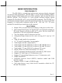
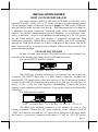
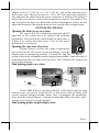
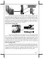
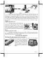
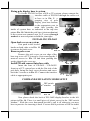
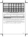
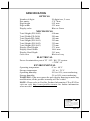
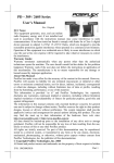
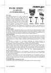
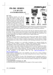
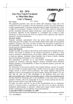
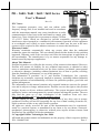
PD – 2600 / 2601 / 2602 / 2603 Series
User’s Manual
Rev. C0
FCC Notes:
This equipment generates, uses, and can radiate radio
frequency energy and, if not installed and used in accordance
with the instructions manual, may cause interference to radio
communications. It has been tested and found to comply with
limits for a Class A digital device pursuant to subpart J of Part
15 of FCC Rules, which are designed to provide reasonable protection against
interference when operated in a commercial environment. Operation of this equipment
in a residential area is likely to cause interference in which case the user at his own
expense will be required to take whatever measures to correct the interference.
Warranty Limits:
Warranty terminates automatically when any person other than the authorized
technicians opens the machine. The user should consult his/her dealer for the problem
happened. Warranty voids if the user does not follow the instructions in application of
this merchandise. The manufacturer is by no means responsible for any damage or
hazard caused by improp er application.
About This Manual:
Posiflex has made every effort for the accuracy of the content in this manual. However,
Posiflex will assume no liability for any technical inaccuracies or editorial or other
errors or omissions contained herein, nor for direct, indirect, incidental, consequential
or otherwise damages, including without limitation loss of data or profits, resulting
from the furnishing, performance, or use of this material.
This information is provided “as is” and Posiflex Technologies, Inc. expressly
disclaims any warranties, expressed, implied or statutory, including without limitation
implied warranties of merchantability or fitness for particular purpose, good title and
against infringement.
The information in this manual contains only essential hardware concerns for general
user and is subject to change without notice. Posiflex reserves the right to alter product
designs, layouts or drivers without notification. The system integrator shall provide
applicative notices and arrangement for special options utilizing this product. The user
may find the most up to date information of the hardware from web sites:
http://www.posiflex.com or http://www.posiflex.com.tw
All data should be backed-up prior to the installation of any drive unit or storage
peripheral. Posiflex will not be responsible for any loss of data resulting from the use,
disuse or misuse of this or any other Posiflex product.
All rights are strictly reserved. No part of this documentation may be reproduced,
stored in a retrieval system, or transmitted in any form or by any means, electronic,
mechanical, photocopying, or otherwise, without prior express written consent from
Posiflex Inc. the publisher of this documentation.
© Copyright Posiflex Technologies, Inc. 2008
All brand and product names and trademarks are the property of their respective holders.
P/N: 19460901140
Part 1
BRIEF INTRODUCTION
THE PRODUCT
The PD-2600 is a stand alone pole mount customer display designed
for discrete POS applications. The PD-2601 is a pole mount customer display
option designed for Posiflex HT series POS terminals and also the PB series
discrete systems . The PD-2602 is a pole mount customer display option
designed for Posiflex KS or TP series touch POS terminals. The PD-2603 is a
pole mount customer display option designed for Posiflex FT series touch POS
terminals. It is delivered in separate carton for HT / PB / KS / TP / FT series
and shall be installed per instruction in this manual.
•
•
•
•
•
•
•
•
•
•
•
•
•
•
•
•
•
•
FEATURES
Bright VFD (vacuum fluorescent display) with green or blue filter
Rear mount Pole Display for Posiflex HT series hybrid terminals or
PB series discrete systems or KS or FT series fan free touch POS
terminals or TP series touch POS terminals
Two-line display with 20 characters per line
Adequately large characters for easy viewing (9.03 mm by 5.25
mm)
Long life and trouble free operation
15°
, 30°
and 45°adjustable viewing angles
Total height 410 mm (Stand alone)
Total height 392 mm (PD-2601 on base of HT and PB series)
Total height 325 mm (PD-2602 on base of KS and TP series)
Total height 375 mm (PD-2603 on base of FT series)
Display frame can rotate horizontally 270° freely
Various command emulation modes selectable by DIP switch
Support 12 Code Pages of 128 characters each
Support 12 international character sets of 12 characters each
Simple installation
Selectable between Serial (RS232) interface model and USB
interface model
Supports UPOS 1.8 and is WEPOS ready
Case color choices: ivory, black for HT terminals or black for FT,
KS and TP terminals
Part 2
INSTALLATION GUIDES
HOST SYSTEM PREPARAION
For serial interface (RS232) PD-2601or PD-2602 or PD-2603 to be
used in HT or PB or KS or TP or FT series, you have to adjust during power
off the internal jumper of the host system to supply 5 V DC to the COM port
selected for the serial interface pole display. This adjustment has to be done by
a qualified electronic technician following guide from relevant technical
manual. The default communication protocol should be set to 9600 bps, none
parity, 8 data bits, 1 stop bit with hardware handshaking on CTS. The power
for the USB interface type pole display is supported through the USB
connection. However, should these customer displays are to be connected
through an USB HUB instead of a direct USB port of the system, the HUB
must be powered by a separate power adaptor otherwise there could be the
power shortage problem.
INSTALLING PD-2600
In base of stand alone models (PD-2600 models only), looking from
rear side of the bottom, the connector area will look like below:
For serial (RS232) interface models:
To Display head
RS232
24 VDC
In
24 VDC
12 VAC In
The RJ45 type modular connector is for internal use and is already
occupied. The RS232 input port is a DB9 female connector. Connect the
attached RS-232 signal cable to this port and one of the COM port in the host
system. Set the RS-232 communication protocol for this port to 9600 bps, no
parity, 8 bits, 1 stop bit with hardware handshaking. Connect the power
adaptor to the rightmost power connector. Turn on the switch in the front side
of the base.
For USB interface models:
USB
To Display head +24 V DC Out +24 V DC In 12 VAC In
The RJ45 type modular connector is for internal use and is also
already occupied. Connect the “B” type connector of the interface cable to
“USB” in connector area and the “A” type end to USB port of the host. Insert
the 2 pin or 3 pin power connector from either 12 V AC or +24 V DC power
Part 3
adaptor to the“12 V DC In” or “+24 V DC In” jack in the connector area.
Insert either end of the power cable to “+24 V DC Out” jack in the connector
area and insert the other end to the power connector of Posiflex POS printer if
needed. Be sure to hear a click at each connection to obtain a firm contact. You
may now place the base on a horizontal surface and prepare to power on and
adjust the direction of the display head for best viewing effect in application.
INSTALLING PD-2601
Opening the back cover on system
For ease of PD-2601 installation operation, the HT
main unit or PB system has to be opened with sufficient
precautions. First push in the circled knobs on both sides as
in Pix. 1 to remove the back cover. Take out the arrow
pointed pole cover from it.
Opening the top cover of system
Prepare a piece of clean soft clothe of appropriate
size in front of the HT system to prevent damage. Turn the
dis play panel to straight up position. For both HT and PB
Pix. 1
system, push in the rectangular marked spring button in Pix. 1 on both sides of
chassis and raise the rear edge of the top cover. The COM port DC support can
be set at this moment.
Find joining points on system
B
B
A
C
C
A
Pix. 2
Refer to Pix. 2 that is a picture of the HT or PB chassis near the right
bottom corner (as you are facing the HT or PB system from its back) with
several portions enlarged around, please find 2 rectangular PD installation
holes A on the bottom chassis; 2 circular locating holes B on I/O plate; and 2
circular screw holes C on metal sidewall.
Find joining points on pole display base
Part 4
B’
B’
C’ C’
A’
A’
Pix. 3
Take PD-2601 out of its box and refer to Pix. 3 that is a picture of the
pole display base unit (lowest part of the PD) with 2 enlarged portions to the
right and a slightly enlarged side view picture to the left to find 2 bottom
locking lugs A’; 2 short cylindrical locating bosses B’ to fit into I/O plate; and
2 plastic screw bosses C’ on side. Please note that the PD cable comes out of
the bottom end of the base tube yet in the illustration pictures the cable is
eliminated for sake of minimum visual confusion.
Insert bottom locking lugs
A
Pix. 4
A’
Turn the pole display base unit opposite to have the bottom locking
lugs A’ in Pix. 3 facing left and now insert the 2 bottom locking lugs A’ on
base unit into the 2 rectangular installation holes A on bottom of HT or PB
chassis from the right corner with the pole display slightly inclined to the left
as in Pix. 4. Please note that both bottom locking lugs A’ should be completely
inserted and come out of the bottom plate of HT or PB system as emphasized
by an arrow in the enlarged portion.
Fit in locating bosses
Please always keep a gentle pressure at the bottom end of pole base
(bottom locking lugs A’) to the left (away from the sidewall of system chassis)
when moving the upper part of pole toward sidewall and matching the 2 short
cylindrical locating bosses B’ into 2 round holes B in the I/O plate. Please refer
to Pix. 5 to see the 2 locating bosses B’ from inside of HT or PB system.
Part 5
B+B’
B+B’
A’
Pix. 5
Please note the importance of keeping the leftward pressure on
bottom end of pole display during the process of turning the pole upright and
inserting the locating bosses B’ or even when you want to release the locating
bosses B’ away from I/O plate B and turn the upper end of pole display to left
to remove the locking lugs A’ from bottom chassis A. Ignorance of this point
may damage or even break off the locking lugs A’ due to improper torque
applied.
Apply sidewall screw
The screw bosses of PD-2601 base PD-2601 Base
should now align with the screw holes on
sidewall of system chassis. Only 1 screw
needs to be applied. Use the self-tapping
C+C’
screw that comes with PD-2601 to fix from
external side of sidewall as demonstrated in
Outside of sidewall
Pix. 6.
Pix. 6
Connect interface cable
Carefully close back the top cover of HT or PB system and connect
the interface cable of PD-2601 to appropriate port in system connector area.
Then close the back cover of the system.
INSTALLING PD-2602
Opening the rear connect cover on system
To install PD-2602 to the base of KS or TP systems, the rear connect
cover on its base has to be removed as described in
the user’s manual. The plastic
hook plate to remove the rear
connect cover in slim base is
indicated in Pix. 7 and that for
universal base is indicated in
Pix. 7
Pix. 8.
Pix. 8
Part 6
Fixing pole display base to system
To fix the PD-2602 to base of KS or TP systems, please connect the
interface cable of PD-2602 through the cable exit
in base as in Pix. 9 a
peeping view of pole
display joint base bottom
to the appropriate port in
Pix. 9
main unit passing the
inside of system base as indicated in the top-view
picture Pix. 10. Match the pole base (joint mechanism)
to the system rear connect area Fit 2 screws through
Pix. 10
washers at arrowed points to hold the joint tight.
INSTALLING PD-2603
Open back cover on system
First push in the circled
knobs on both sides as in Pix. 11
to remove the back cover.
Pix. 11
Remove pole cover
Remove the pole cover on rear edge of the
base top cover of FT system by first removing the 2
arrowed screws in Pix. 12 and then pushing the
wedge shaped pole cover up.
Install PD and connect interface cable
Pix. 12
Insert the base of PD-2603 / PD-2603U
from top of FT system base with the flat side of the
pole base facing the back cover direction and screw
back the 2 screws as in Pix. 13. Connect the interface
cable to appropriate port.
Pix. 13
COMMAND EMULATION MODE SETUP
DIP switch
window
Pix. 14
Now please check the back of PD-260X display head as in the left
picture in Pix. 14. There is a small piece of plastic cover for the “DIP switch
window”. Slide the cover downward but don’t pull it off otherwise you may
have to practice for inserting it back. You can find 6 positions of DIP switches
Part 7
in this window. Adjust for the appropriate command mode used by the
application program according to below table. Switch position counts from left
to right and “ON” means pushed up as indicated in the right part in Pix. 14.
Switch Position
Command Mode
1
2
3
4
5
6
ON OFF OFF ON OFF OFF
ADM
ON OFF ON
ON OFF OFF
Aedex
ON OFF ON OFF OFF OFF
Epson
ON OFF OFF ON
ON OFF
Futaba
ON OFF ON OFF ON OFF
Noritake
ON OFF ON
ON
ON OFF
UTC
The factory default command mode is set to Noritake mode for
normal delivery. Please change it to Epson mode if OPOS or UPOS driver is
used for the application program.
POWER ON SIGN
With interface cable connection well installed (and with COM port
power set for serial models), turn on the HT or KS or TP Posiflex POS system,
a firmware identifier as power on sign will appear on the pole display screen
for a while to indicate that pole display is self-tested O.K. and ready to work.
USING THE CUSTOMER DISPLAY
INTERRFACE SELECTION
This series of customer display is designed to serve in HT / KS / TP /
FT series Posiflex POS systems with RS232 interface models and with USB
interface models. It is advisable to well study the I/O port availability of the
host system before determining which interface model to be used.
When a RS232 (serial) interface model of PD-2601 / 2602 / 2603 is
used, the jumper on main board of HT / KS / TP / FT system must be modified
to supply power to the COM port designated for PD-2601 / 2602 / 2603.
Whenever the RS232 interface PD-2601 / 2602 / 2603 is to be removed from
the HT / KS / TP / FT system, consequently the jumper has to be changed back
to neutralize the COM port, otherwise damage could occur!
The USB interface model of PD-2601 / 2602 / 2603 should be
connected directly to an USB port and must not be through any non-selfpowered USB HUB to get power through the USB port itself and there is no
need for other special arrangement.
COMMAND MODE SELECTION GUIDE
The below table provides some comparison for selection on command
mode to be used in the application program if it is not yet determined.
Part 8
Mode
ADM
Aedex
Cursor
N.A.
N.A.
Default mode
N.A.
N.A.
User defined font
N.A.
N.A.
Brightness control
Leading code change
Code page select
Auto scroll message
Timer clock
NO
NO
NO
NO
NO
NO
YES
NO
NO
NO
Epson
Futaba
Noritake UTC
Blinking Blinking Blinking
Invisible
Block
Block
Block
(DP)
Over/W V. scroll Over/W PT
2 chars N.A.
2 chars 2 chars
(PT)
YES
YES
YES
YES (DP)
NO
YES
YES
YES (PT)
YES
YES
YES
YES
NO
YES
YES
YES (PT)
YES
NO
NO
YES (PT)
DRIVER INSTALLATION
For application software to use RS232 interfaced PD-260X, there is
no direct need for any driver. The OPOS (OLE POS) driver or the JPOS (Java
POS) driver would be required for OPOS or JPOS programs and the PD-260X
would have to be set to “Epson” command mode. These drivers are available
from
our
web
page:
http://www.posiflex.com.tw/Download%20list.asp?Status=1&Series_Name=U
POS&Model_Name=OPOS and execute the file “SETUP.EXE” to install the
OPOS Control Manager. To add the customer display under OPOS control
please set in OPOS Control Manager device name “PD2x-Line Display” in the
top row. For RS-232 models, select the COM port in the 3rd row and set baud
rate to “9600” in 4th row as in the left sample screen below. Select “USB” in
3rd row for USB interface models as in the right sample picture below.
For USB interfaced PD-260X, please visit our web site and find the
driver from the class “PD23_26U”. The guidance for each function call in the
library “USBPD.dll” is covered in the “ReadMe” file in that class.
Part 9
SPECIFICATION
OPTICAL
Number of digits
Dot matrix
Digit height
Digit width
Display color
20 digits/row, 2 rows
5 X 7 dots
9.03 mm
5.25 mm
Blue or Green (505 nm)
MECHANICAL
Total Height (PD-2600)
Total Width (PD-2600)
Total Depth (PD-2600)
Total Height (PD-2601)
Total Height (PD-2602)
Total Height (PD-2603)
Display Head Height
Display Head Width
Display Head Depth
Case color
410 mm
220 mm
110 mm
392 mm
325 mm
375 mm
57.5 mm
196.6 mm
39.5 mm
Black or Ivory
ELECTRICAL
Power from interface port of FT / HT / KS / TP system:
+ 5VDC 1A
ENVIRONMENTAL
Operating temperature
0° to + 40°C
Storage temperature
-20° to + 70°C
Operating humidity
20% to 85%, non-condensing
Storage humidity
5% to 90%, non-condensing
WARNING: If the user opens the pole display housing to make any
modification, all the product warranty will be voided.
NOTE: Please refer to Posiflex Product Information CD or DVD or
visit our web http://www/posiflex.com.tw for further information
when needed.
Weight
1.3 kgs (2.86 lbs) (excl. power adaptor)
Vibration resistance 4 G max. (half amplitude 0.15mm)
Impact resistance
40 G, 11 ms wave, 5 times for each of the
X, Y and Z directions
T31454
警告使用者
這 是 甲 類 的 資 訊 產 品, 在居住的環
境中使用時,可能會造成射頻干
擾, 在 這 種 情 況 下 ,使用者會被要
求採取某些適當的對策 。
Part 10