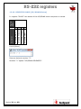
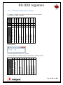
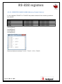
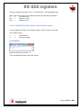
1
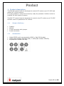
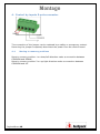
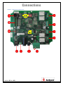
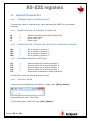
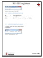
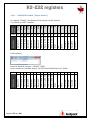
261287-261377 Besturingsprint User manual Gebruikshandleiding Read the manual carefully before installing. Lees aandachtig de gebruiksaanwijzing alvorens te beginnen met de installatie. Bitte beobachten Sie den Gebrauchsanleitung bevor Sie anfangen mit installieren! S'il vous plaît, lisez attentivement le mode d'emploi avant commencer l'installation! 2 Index Table of Contents 1. Product description .......................................................................... 5 1.1. Scope of delivery ....................................................................... 5 1.2. Accessories ............................................................................... 5 2. Required for installation ................................................................... 6 2.1. Tools ........................................................................................ 6 2.2. Experiences .............................................................................. 6 2.3. Homing .................................................................................... 6 3. Control by inputs 6-pole connector .................................................... 7 3.1. Moving to memory positions ....................................................... 7 3.2. To set a memory position ........................................................... 7 4. 4.1. 5. Control by inputs 5-pole connector .................................................... 8 Moving to memory positions ....................................................... 8 Control by RS-232 serial communication ............................................ 9 5.1. Connection of the RS232 ............................................................ 9 5.2. Moving the lift by serial communication (RS-232) .......................... 9 6. General information ....................................................................... 10 6.1. Definitions .............................................................................. 10 6.2. End switches ........................................................................... 10 6.3. Memory positions and directions ................................................ 10 6.4. Memory position control ........................................................... 11 6.5. Error reset .............................................................................. 11 7. Program rotary switch (SW1).......................................................... 12 7.1. Precautions ............................................................................. 12 7.2. Rotary switch positions versus functions ..................................... 12 7.3. Rotary switch positions versus product examples ......................... 13 8. Function dipswitches (J14) ............................................................. 14 9. Serial communication RS-232 ......................................................... 15 9.1. Connections ............................................................................ 15 9.2. Software................................................................................. 16 10. Electric connections ....................................................................... 16 11. Keypad (261288) .......................................................................... 19 12. INSTRUCTIONS RS232................................................................... 20 III Index 12.1. TERMINAL INPUT INSTRUCTIONS .............................................. 20 12.2. INSTRUCTIONS TO CONTROL THE MOTOR .................................. 20 12.3. INSTRUCTIONS TO MOVE THE MOTOR TO A MEMORY POSITION ... 20 12.4. PROGRAM MEMORY POSTIONS .................................................. 20 12.5. FACTORY MODE....................................................................... 20 12.6. MISCELLANIOUS INSTRUCTIONS ............................................... 21 12.7. REGISTER R1000 [Device Name] ............................................... 21 12.8. REGISTER R1001 [Input Status] ................................................ 22 12.9. REGISTER R1002 [Control Function] .......................................... 23 12.10. REGISTER R1003 [UP/DOWN Status] ...................................... 24 12.11. REGISTER R1004 (Motor Status] ............................................ 25 12.12. REGISTER R1005-R1008 [Memory Preset Values) ..................... 26 12.13. REGISTER R1009 [Request Count] .......................................... 27 12.14. REGISTER R1010 [Motor Position Count] ................................. 27 12.15. REGISTER R1011 [Motor Error] .............................................. 28 12.16. REGISTER R1012 [Motor Speed Slow mode] ............................ 29 12.17. REGISTER R1013 [Memory Preset Status]................................ 30 12.18. REGISTER R1014 [Delta pulse] ............................................... 31 12.19. REGISTER R1015 [Master/Slave Mode] .................................... 31 12.20. REGISTER R1016 [Single/Parallel Mode] .................................. 32 12.21. REGISTER R1017 (Soft Start Mode] ........................................ 32 12.22. REGISTER R1018 [Pulse/Continue Mode) ................................. 33 12.23. REGISTER R1019 [Adjustable Speed Limit Mode] ...................... 33 12.24. REGISTER R1021 [limit switch hysteresis homing] .................... 34 12.25. REGISTER R8888 [Software Version]....................................... 34 13. IV Specifications ............................................................................... 35 13.1. Technical data ......................................................................... 35 13.2. AC output relays (261287)........................................................ 35 14. Maintenance ................................................................................. 36 15. Dimensions and illustrations ........................................................... 37 16. Frequently asked questions ............................................................ 38 Product 1. Product description The 261287 control board is developed to control DC-motors up to 30 VDC and switch AC 230 Volt motors. It is also possible to control AC motors by relay dry contacts. Position control is possible for both types of motors. The 261377 control board is developed to control only DC-motors up to 30 VDC. Position control is possible for DC motors. 1.1. Product Manual 5-pole connector with jumper 6-pole connector 1.2. Scope of delivery Accessories Cable RS232 serial communication RJ45 Sub-D9 (female) Cable serial adapter Sub-D9 (male) USB (Part number 320139) Keypad(Part number 261288) Pagina 5 van 40 Montage 2. Required for installation 2.1. Tools To install the product, the following tools are required; 2.2. Experiences Basic electrical knowledge is recommended. 2.3. Homing If the control board will be used with position control the reference or home position have to be set. Position control is available on program number “1”, “2”, “3” en “5”. The procedure for homing is as follows: The motor runs in low speed to down limit switch The motor stops when the (down) limit switch is activated The motor runs in low speed in de reverse direction The motor stops 10 count after the (down) limit switch is deactivated !! In program number “5” homing is in the opposite direction !! (limit switch “UP” will be activated) Homing can be activated by: Keypad RS-232 Program number “2” Pagina 6 van 40 + home, enter auto homing Motor control by input terminals 3. Control by inputs 6-pole connector M1 M2 M3 M4 SET COM 3.1. Move Move Move Move 3.2. Moving to memory positions to to to to memory memory memory memory position position position position 1 2 3 4 make make make make a a a a connection connection connection connection between between between between COM COM COM COM + + + + M1 M2 M3 M4 To set a memory position To set a memory position: Make an Maintain Make an depends interconnection between COM + SET this interconnection, and interconnection between COM + M1, M2, M3 or M4, on the memory you want to store. Disconnecting all the above connections will set the required memory position. (an audible “click” is notable) Pagina 7 van 40 Montage 4. Control by inputs 5-pole connector The connection of the jumper can be replaced by a safety or emergency contact. Removing the jumper completely disconnect the power from the control board. 4.1. Moving to memory positions Move to memory position 1 or down/left direction make a connection between COMMON and DOWN. Move to memory position 2 or up/right direction make a connection between COMMON and UP. Pagina 8 van 40 Motor control by RS-232 5. Control by RS-232 serial communication 5.1. 5.2. Connection of the RS232 Moving the lift by serial communication (RS-232) Moving up Moving down To M1 To M2 To M3 To M4 = = = = = = “o” enter (alphabetic letter) “n” enter (alphabetic letter) “m1” enter “m2” enter “m3” enter “m4” enter For more information see register manual 1.1 and 1.2 Pagina 9 van 40 Montage 6. General information 6.1. Definitions Homing - Move motor to zero or reference point (counter) Twin mode - Parallel or synchronous mode for 2 separate drive units 6.2. End switches End switches, also called limit switches restrict the movement of the motor in both directions. The limit switches are related to the rotation direction of the motor. It is important to connect the motor so that the direction of motion corresponds to the controls and limit switches. In any case the movement stops on both switches, but when the motion direction and limit switch do not match, the two led’s (U2 and U3) of the corresponding limit switches on the PCB start blinking. 6.3. Memory positions and directions The memory positions M1 to M4 must be set in a specific order in between the two limit switches. They differ of the selected program and are also related to the buttons of the remote control. Program “0” and “4” M1 correspond with the left/down direction M2 correspond with the right/up direction M3 is not assigned M4 is not assigned Program “1” M1 correspond with the left/down memory position between M3 and M4, and down position of the RC (free programmable) M2 correspond with the right/up memory position between M3 and M4, and up position of the RC (free programmable) M3 lowest memory position, close to limit switch down (factory setting) M4 upper memory position, close to limit switch up (factory setting) Program “2”, “3” and “5” M1 correspond with down position of the RC (free programmable) M2 correspond with the up position of the RC (free programmable) M3 memory position is free programmable M4 memory position is free programmable Pagina 10 van 40 General information 6.4. Memory position control Memory position M1 to M4 can be set in three different ways. By the keypad on the electrical control box By the memory and motor control terminal By serial communication via RS-232 In program number “1” M3 and M4 are protected and can only be stored using a PIN-code. Set the memory position by the foil switch 6.5. Error reset All errors can be reset by disconnecting the power from the control board. Take at least 10 seconds to power up. The only exception is if two control boards are in twin mode. If an synchronous error occurs then both motors have to be reset and homed separately. Taking into account of mechanical damage. Pagina 11 van 40 Settings 7. Program rotary switch (SW1) 7.1. Precautions Before changing the program state disconnect the power from the control board. Set memory positions under load. Place the projector or flat screen before storing the memory positions. 7.2. Rotary switch positions versus functions Rotary switch on position “0” = DC motors up to 30VDC without position control Rotary switch on position “1” = DC motors up to 30VDC, column lifts with intern limit switches and position control. Rotary switch on position “2” = DC motors up to 30VDC with external limit switches and position control, auto homing. Rotary switch on position “3” = DC motors up to 30VDC with external limit switches and position control, manual homing. Rotary switch on position “4” = Single phase AC tube motors with external limit Switches . Rotary switch on position “5” = Single phase AC tube motors with external limit Switches and position control, manual homing. (4 & 5 not applicable on PCB 261377) Pagina 12 van 40 Settings 7.3. Rotary switch positions versus product examples Rotary switch on position “0” = MKT-150WS, MKT-200WS, MKT-250WS, MKT-265WS Rotary switch on position “1” = FFCL-XXXX, Column lifts Rotary switch on position “2” = PRK-250, PRK-500, PRK-750, PCL-M350, PCL -X350 and MKT-C150 Rotary switch on position “3” = PRK-250, PRK-500, PRK-750, PCL-M350, PCL -X350 and MKT-C150 Rotary switch on position “4” = Universal AC tube motors Rotary switch on position “5” = PCL-1070, PCL-2050, PCL-3050, PCL-5050 Switches and position control, manual homing. (4 & 5 not applicable on PCB 261377) Pagina 13 van 40 Settings 8. Function dipswitches (J14) Dipswitch position 1 = Master/slave - slave “on” (in twin-mode only) Dipswitch position 2 = Single/twin - single mode “on” Dipswitch position 3 = Soft start/stop on/off - soft start/stop “on” Dipswitch position 4 = Pulse/continue - pulse “on” !! When pulse is “on”, the direction buttons are working as a latching switch !! Dipswitch position 5 Pagina 14 van 40 = Speed limit on/off – speed limit “on” Connections 9. Serial communication RS-232 Cable RS232 serial communication RJ45 Sub-D9f (Part number 320137) Cable serial adapter Sub-D9 (male) USB (Part number 320139) 9.1. Connections Put the RJ-45 male connector into female connector on the control board and into the Sub-D9 male connector of your computer. Pagina 15 van 40 Connections If your computer doesn’t have a serial Sub-D9 serial port connector, a serial adapter Sub-D9 (male) USB cable is needed. (Part number 320139) 9.2. Software An example of a terminal emulator software to control the control board is “PuTTY” and can be found to follow this link: http://the.earth.li/~sgtatham/putty/latest/x86/putty.exe 10. Electric connections POWER SUPPLY Pagina 16 van 40 Connections and are power supply connections up to 30 Volt DC. Connector is suitable for a barrel plug with a diameter of 5.5 mm. The inner contact also called tip is the positive pole (+) Connector external control Motor terminal DC Relays output UP/DOWN Terminal limit switches Sensor counter Serial communication (RS232) Heartbeat cable connector Connector memory position control and memory store function Connector keypad R1 = R2 = R80 = Potentiometer for maximum motor current Potentiometer for maximum motor voltage (% of power supply) Potentiometer supply voltage counter sensor (factory setting = 5VDC) Pagina 17 van 40 Connections Table 1 - Electrical connections R2 R1 R80 Pagina 18 van 40 Keypad 11. Keypad (261288) With the keypad in combination with the control board (261287 or 261377) button control Table 2 – Buttons keypad (part number: 261288) Go to memory position 1 Go to memory position 2 Go to memory position 3 Go to memory position 4 Set memory in combination with 1,2,3 or 4 Moving direction Up/right Moving direction Down/left + Set memory position 1 Memory indicator LED1 turns from orange (pushed) to green (released) + Set memory position 2 Memory indicator LED2 turns from orange (pushed) to green (released) + Pin Set memory position 3 with PIN-code Memory indicator LED3 turns from orange (pushed and released) to green (pin-code correct) + Pin Set memory position 4 with PIN-code Memory indicator LED4 turns from orange (pushed and released) to green (pin-code correct) + Toggle between fast and slow motion (DC output only) + “Homing” “Reset” the control board by pushing all buttons together during power up. Memory positions remain there current value Pagina 19 van 40 RS-232 registers 12. INSTRUCTIONS RS232 12.1. TERMINAL INPUT INSTRUCTIONS The terminal input or instruction by other devices thru RS232 or not context sensitive. 12.2. B N O S 12.3. M1 M2 M3 M4 12.4. P1 P2 P3 P4 PF INSTRUCTIONS TO CONTROL THE MOTOR = = = = Switch slow/fast model (DC Output only) Move motor down Move motor up Motor stop INSTRUCTIONS TO MOVE THE MOTOR TO A MEMORY POSITION = = = = Go Go Go Go to to to to memory memory memory memory position position position position 1 2 3 4 PROGRAM MEMORY POSTIONS = = = = = Set Set Set Set Set new value for memory position 1 new value for memory position 2 new value for memory position 3 new value for memory position 4 memory positions to factory settings P3 and P4 can only be stored in factory mode. 12.5. FACTORY MODE To set the control board into the factory mode, type: [Esc]~[Enter] Returns with the text: “FM is ON” To turn the factory mode off, type: [Esc] [Enter] Pagina 20 van 40 RS-232 registers Returns with the text: “FM is OFF” 12.6. MISCELLANIOUS INSTRUCTIONS D = R<X> = W<X>=<data> V<X> = K<X> = 12.7. Switch debug on/off Read register <X> = Write <data> into register X Set PWM motor speed <X> (0 < X > 1023) Set motor position in counts (50 < X > 60000) REGISTER R1000 [Device Name] In register “R1000” the device name is stored . R1000[Enter] Returns “AUDIPACK DUAL UNIT” Pagina 21 van 40 Preset M3 Preset M2 Preset M1 1 1 0 1 0 0 0 0 1 0 0 0 0 0 0 0 Pagina 22 van 40 Dipswitch 4 Dipswitch 3 Rotary switch bit3 Rotary switch bit2 Rotary switch bit1 Rotary switch bit0 Down Up Store Preset M4 Preset M3 Preset M2 Preset M1 256 128 64 32 16 8 4 2 1 9 8 7 6 5 4 3 2 1 0 Rotary switch bit1 Rotary switch bit0 Down Up Store Preset M4 1024 2048 4096 9192 18384 36768 65536 131072 Register R1001 516 18 Bits 17 16 15 14 13 12 11 10 Rotary switch bit2 Rotary switch bit3 Dipswitch 3 Dipswitch 4 Dipswitch 5 Dipswitch 2 Limit Switch Down Limit Switch Up 1 Dipswitch 5 18 Bits 0 Dipswitch 2 Returns decimal number “118912” (DEC) and is equal to a 18-Bits binary “0100011000100100010010” (BIN) Limit Switch Down R1001[Enter] Limit Switch Up Dipswitch 1 Description 12.8. Dipswitch 1 Description RS-232 registers REGISTER R1001 [Input Status] In register “R1001” the status of the inputs can be viewed. The result is a DEC number. RS-232 registers 12.9. REGISTER R1002 [Control Function] In register “R1002” the status of the control function input is stored. This number could be “0” or “4”. R1002[Enter] Returns “1” Table 3 – Rotary switch control function Position Description 0 DC motor control without position control 1 DC motor control with position control and build in limit switches (e.g. columns) 2 DC motor control with position control auto homing 3 DC motor control with position control manual homing 3 Relay output control without position control 4 Relay output control with position control Connector (manual) (manual) (manual) (manual) (manual) (manual) Pagina 23 van 40 RS-232 registers 12.10. REGISTER R1003 [UP/DOWN Status] 3 2 1 0 UP/DOWN RELEASED UP/DOWN PRESSED UP/DOWN START Description DEC UP/DOWN STOP Register R1003 In register “R1003” the status of the UP/DOWN motor sequence is stored. R1003[Enter] Returns decimal number “2”. Number “2” equals “UP/DOWN RELEASED”. Pagina 24 van 40 RS-232 registers 12.11. REGISTER R1004 (Motor Status] 8 4 2 1 3 2 1 0 MOTOR PRESET 1 16 4 MOTOR PRESET 2 32 5 MOTOR PRESET 3 64 6 MOTOR PRESET 4 128 7 MOTOR UP 256 8 MOTOR DOWN MOTOR CONNECTION ERROR Description 10 Bits 9 MOTOR CURRENT ERROR 512 Register R1004 In register “R1004” the status of the motor can be viewed. The result is a DEC number. R1004[Enter] 0 0 0 0 MOTOR PRESET 1 0 MOTOR PRESET 1 0 MOTOR PRESET 1 1 MOTOR PRESET 1 0 MOTOR UP 0 MOTOR DOWN 0 MOTOR CURRENT ERROR Description 10 Bits MOTOR CONNECTION ERROR Returns decimal number “64” (DEC) and is equal to a 10-Bits binary “0001000000” (BIN) number. Pagina 25 van 40 RS-232 registers 12.12. REGISTER R1005-R1008 [Memory Preset Values) In the registers “R1005” to “R1008” the preset values of the memory positions are stored. Register R1005 R1006 R1007 R1008 Description M1 counter M2 counter M3 counter M4 counter value value value value Value range 50-60000 counts 50-60000 counts 50-60000 counts 50-60000 counts R1005[Enter] R1006[Enter] R1007[Enter] R1008[Enter] Returns decimal numbers “1010”, “2000”, “130”, “2600”. Pagina 26 van 40 RS-232 registers 12.13. REGISTER R1009 [Request Count] In the register “R1009” the “Requested count” is stored. R1009[Enter] Returns decimal number “2000”. 12.14. REGISTER R1010 [Motor Position Count] In the register “R1010” the “Motor position” is stored. R1010[Enter] Returns decimal number “2000”. Pagina 27 van 40 RS-232 registers 12.15. REGISTER R1011 [Motor Error] In the register “R1011” the “Motor error” is stored. Register Value Error Hexadecimal [decimal] R1011 1[1] Current error (DC output only) Current is higher than adjusted current value or Current is too low when motor is activated 2[2] Motor connection error (DC output only) Limit switch up activated when motor runs down Limit switch down activated when motor runs up 4[4] Motor sync error (parallel mode) Number of pulses between master and slave is too many 8[8] Heartbeat error (parallel mode) Slave receives no heartbeat from master (connection error) 10[16] Limit switch error Limit switch up/down activated when motor is between memory position M1 or M2 20[32] Pulse error Time between pulses is too long 40[64] CRC error EEPROM error 80[128] Memory error Motor didn’t reach the requested position 100[256] Slave error (parallel mode) Error occurred in slave device 200[512] Master error Error occurred in master device R1011[Enter] Returns decimal number “0”. No error occurred. R1011[Enter] Pagina 28 van 40 RS-232 registers Returns decimal number “641”. 641 decimal = 281 hexadecimal. When 1 80 200 we look at the error table we find the following numbers: = Current error = Memory error = Master error 12.16. REGISTER R1012 [Motor Speed Slow mode] In the register “R1012” the preset status “Slow mode” is stored. (DC output only) 1 0 = = Slow mode No slow mode R1012[Enter] Returns decimal number “0”. This represents preset: No slow mode Pagina 29 van 40 RS-232 registers 12.17. REGISTER R1013 [Memory Preset Status] In the register “R1013” the status “Calibration” is stored. 0 = Memory preset ready 1 = Preset memory position 1 request Set memory position 1 Memory indicator LED1 turns from orange (pushed) to green (released) + 2 = Preset memory position 2 request Set memory position 2 Memory indicator LED2 turns from orange (pushed) to green (released) + 4 = Preset memory position 3 request Set memory position 3 with PIN-code Memory indicator LED3 turns from orange (pushed) to green (released) + 8 = Preset memory position 4 request Set memory position 4 with PIN-code Memory indicator LED4 turns from orange (pushed) to green (released) + 16 = New value is stored R1013[Enter] Returns decimal number “0”. This represents preset: Ready to preset a memory position Pagina 30 van 40 RS-232 registers 12.18. REGISTER R1014 [Delta pulse] In the register “R1014” the “delta pulse” is stored. R1014[Enter] Returns decimal number “40”. 12.19. REGISTER R1015 [Master/Slave Mode] In the register “R1015” the preset “Master/Slave mode” is stored. (DC output only) 1 = Master 0 = Slave R1015[Enter] Returns decimal number “1”. This represents preset: Master Pagina 31 van 40 RS-232 registers 12.20. REGISTER R1016 [Single/Parallel Mode] In the register “R1016” the preset “Single/Parallel mode” is stored. (DC output only) 0 = Single mode 1 = Parallel mode R1016[Enter] Returns decimal number “0”. This represents preset: Single mode 12.21. REGISTER R1017 (Soft Start Mode] In the register “R1017” the preset status “Soft start mode” is stored. (DC output only) 0 = Ramp up/down 1 = No ramp up/down R1017[Enter] Returns decimal number “1”. This represents preset status: No ramp up/down Pagina 32 van 40 RS-232 registers 12.22. REGISTER R1018 [Pulse/Continue Mode) In the register “R1018” the preset “Pulse/Continue mode” is stored. (DC output only) 0 = Pulse (latch) 1 = Continue (closed contact) R1018[Enter] Returns decimal number “1”. This represents preset: Continue (Up/Down NO-contact must be continue closed to run the motor) 12.23. REGISTER R1019 [Adjustable Speed Limit Mode] In the register “R1019” the preset status “Speed limit ” is stored. (DC output only) 0 = Speed limit 1 = No speed limit R1019[Enter] Returns decimal number “1”. This represents preset status: No speed limit The speed (PWM output voltage) can be adjusted by potentiometer R2. !! The output voltage is a percentage of the supply voltage !! Pagina 33 van 40 RS-232 registers 12.24. REGISTER R1021 [limit switch hysteresis homing] In the register “R1021” the value of the limit switch hysteresis for homing is stored. The factory setting is “10” R1021[Enter] 12.25. REGISTER R8888 [Software Version] In register “R8888” the software version is stored . R8888[Enter] Returns “V11” Pagina 34 van 40 Specifications 13. Specifications 13.1. Technical data Vinput Imax.output Vout.counter Vin.counter 13.2. Vmax Imax Pmax : : : : 12-30 10 5-14 5 Volt DC Ampere Volt DC Volt DC 230 10 500 Volt AC Ampere Watt AC output relays (261287) : : : Pagina 35 van 40 Onderhoud 14. Maintenance N.A. Pagina 36 van 40 Technical data 15. Dimensions and illustrations Pagina 37 van 40 FAQ 16. Frequently asked questions There is an abnormality in the position that you want? Re: Follow the procedure for manual homing. + Control board doesn’t react without error message Re: Follow the procedure for manual homing. + The two led’s (U2 and U3) of de corresponding limit switches are both blinking synchronous Actuated limit switch do not match the motor direction of rotation or Motor current exceeds motor current setting (R2) or Pagina 38 van 40 FAQ Audipack’s general conditions of sales and delivery apply to all of Audipack’s deliveries. These conditions can be downloaded from Audipack’s website, www.audipack.com, or will be send by post on request. Audipack liefert ausschließlich unter die allgemeine Verkauf- und Lieferungsbedingungen von Audipack. Diese Bedingungen sind zum downloaden verfügbar auf die webseite von Audipack, www.audipack.com, oder werden Ihnen auf Anfrage per Post gesendet. Alle leveringen geschieden uitsluitend volgens de Algemene Verkoop- en Leveringsvoorwaarden van Audipack. Een afschrift hiervan kunt u downloaden van de website van Audipack, www.audipack.com, of wordt u op aanvraag gestuurd per post. Les conditions de Vente et de livraison de Audipack s’appliquent à tous les livraisons de Audipack. Cette conditions sont disponible sur le site internet de Audipack, www.audipack.com, où seront envoyé par poste sur demande. AUDIPACK Industriestraat 2-4 2751 GT Moerkapelle The Netherlands Tel: +31(0)795931671 Fax: +31(0)795933115 Email: [email protected] www.audipack.com Audipack reserves the right to make changes in specifications and other information contained in this document without prior written notice. The information provided herein is subject to change without notice. In no event shall Audipack be liable for any incidental, special, indirect, or consequential damages whatsoever, including but not limited to lost profits, arising out of or related to this manual or the information contained herein, even if Audipack has been advised of, known, or should have known, the possibility of such damages.