1
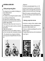
I n v a c a r e Atlas Lite ® ISO 9001 Yes, you can. User guide Foreword The information contained in this manual is subject to change without notice. Some information is submitted under copyright – all rights reserved. Information in this document cannot be photocopied or duplicated without prior written authorization by Invacare. As the Australasian and world leading manufacturer of wheelchairs, Invacare endeavours to supply a wide range of wheelchairs to meet all the needs of the user in everyday life. However, final selection of the wheelchair rests solely with the user and his/her qualified health advisor. Proper and efficient use of the wheelchair that you have chosen is based upon the medical prescription which was issued for you on the basis of your pathology and the nature of your disability. Your wheelchair is especially designed to be used inside, and with certain restrictions outside. Please comply with traffic regulations. Stamp of the Distributor Introduction Dear Customer Thank you for purchasing an Invacare wheelchair. This model was designed to provide you with all the benefits and features to meet your needs. Only quality components were selected for your wheelchair based upon rigorous inspections during the entire manufacturing process. This manual describes the operating limits of your wheelchair, maintenance operations and adjustments that you or your assistant can make. This product conforms to the requirements of Council directives 93/42/EEC related to medical devices class 1(one) product by application of following standards: NF EN ISO 14971 and NF EN 12182. All the repairs (except for inner tubes) as well as some adjustments, require specific technical training and, therefore, must be performed by your distributor. The I n v a c a r e Atlas Lite is designed for both indoor and outdoor use with the purpose of helping people who are not able to walk over a long distance. ® TABLE OF CONTENTS B. DESCRIPTION OF YOUR CHAIR A. GENERAL GUIDELINES Page 2 1. Safety and operating limits 1.1. Reaching an object from the chair 1.2. Sideways transferring to other seats 1.3. Tilting 1.4. Tilting, kerbs 1.5. Stairways 1.6. Slopes 3 5 6 6 7 7 2. Operating instructions 2.1. Folding and Unfolding the wheelchair 2.2. Wheelchair propulsion 2.3. Lifting the wheelchair 8 9 9 3. Safety inspection and maintenance 3.1. Performance control 3.2. General inspection 10 10 4. Transportation 11 5. Warranty 5.1. Standard terms and conditions 5.2. Limitation of liability 12 12 6. Summary of operating instructions 12 1. General 1.1. Introduction 1.2. General description 2. Adjustments 2.1. Seat elements 2.1.1 Padded seat upholstery 2.1. 2 Backrest options 2.1. 3 Backrest upholstery 2.1. 4 Footrest supports 2.1. 5 Armrests 2.2. Frame 2.2.1 Side frame 2.2.2 Folding system 2.2.3 Seat height adjusment 2.3. Rear wheel 2.3.1 24" wheels 2.3.2 Handrims 2.3.3 Axles 2.4. Castors 2.5. Brakes 2.5.1 Manual brakes 2.5.2 Attendant brakes 2.6. O ptions 2.6.1 Transit version Page 3 ls 3.1. Standard wheelchair specifications 3.2. Tools for adjustments and regular maintenance (Not supplied) 3.3 Dimensions 13 13 14 14 15 16 16 17 17 17 18 18 18 18 18 19 19 19 19 20 20 20 21 21 22 A GENERAL GUIDELINES 1. Safety and operating limits For safe operation of your wheelchair, the following parameters should be observed: - Stability and balance Your wheelchair has been designed to provide the stability you need during normal daily activities. Any movement in the wheelchair will have an impact on the position of the centre of gravity, which may lead to the wheelchair tipping and falling. To improve your safety when you move a lot or you transfer your weight from one place to another, we recommend using seat belts. - Weight distribution (figure 1) Many actions cause the user of a wheelchair to reach out, lean over or move about within the wheelchair and outside it. These movements cause a change to normal balance, centre of gravity (G) and weight distribution of the wheelchair. 1 - Weight Limit The maximum recommended weight of the user is 120 kg. However, the level of activity is an essential factor. For example, an active user who weighs 75 kg may subject the wheelchair to more stress than that of a user who weighs 100 kg. To this purpose, we recommend that you consult your retailer when choosing the model of wheelchair based upon your daily lifestyle. 1.1 Reaching an object from the chair The limitations on reaching out from a wheelchair indicated in the following diagrams have been calculated based on a representative sample of wheelchair users: - Only the arms should be extended beyond the seat of the wheelchair (figure 2). - The body and head should remain within the boundaries of the seat (figure 3). 2 3 3 1.1.1 Leaning forward 1.1.2 Leaning backward Do not extend your chest over the armrest (figure 4). In order to reach an object in front of you, you must lean and bend down; therefore, you must use the castors as a tool (pointing them forward) to maintain stability and balance. Accurate alignment of the wheels is essential for your safety (figure 5). Position wheelchair as close as possible to the desired object so that you can simply pick it up by stretching your arm while sitting in the chair in a normal position. Do not lean backwards because you may cause the chair to tip (figures 6 and 7). 4 4 5 6 7 1.2 Sideways transferring to other seats This may be done without assistance provided that you are sufficiently mobile and have a strong enough torso. - Move the wheelchair as close as possible to the seat to which you would like to sit, with the castors pointed forward. Lock the wheels by applying the brakes. Move the weight of your body towards the seat (figure 8) - While moving from the wheelchair to the seat, your body will have little or no support. Where possible use a transfer board during transfers. - If you are more or less able to stand up and if your upper body is sufficiently strong and mobile, you can transfer forward to another seat. Fold the footplates up and push the footrests/legrests to the side, bend your body forward leaning on the two armrests and lift yourself up; then shift your body towards the place where you want to sit while distributing your weight to the arms and hands (figure 9). 8 ! Warning : - Position yourself as close as possible to the place where you wish to sit. - When transferring, position yourself as far back as possible in the seat to prevent breaking screws, damaging the seat upholstery or causing the wheelchair to tip forward. - Lock the two brakes; they should not be used as support for transfers. - Never stand on the footrests when you are getting in or out of the wheelchair (figure 10). 5 9 10 6 1.3 Tilting (balancing on the rear wheels) 1.4 Tilting, Kerbs For greater safety, this operation must be performed by an attendant. The attendant should be aware of the required physical effort and use appropriate positioning in order to relieve the strain on his/her back (keep a straight back and bend knees during this operation). To tilt the wheelchair, the attendant must firmly grab the handles making sure both are properly fixed. The attendant must warn the occupant in the wheelchair before tilting it and remind him/her to lean backwards and make sure that both feet and hands of the occupant are clear of the wheels. Place a foot on the footstep tube and move continuously until the chair reaches the equilibrium point. At this stage, the assistant will feel a difference in weight distribution, which usually occurs at approximately 30°. At this point, the wheelchair can get over the obstacle easily. Finally, the attendant slowly and gradually lowers the front down to the ground, while firmly holding the handles. To get onto the footpath: - Method 1 (figure 11) The attendant positions the wheelchair in front of the footpath facing forward. Attendant tilts the wheelchair backwards until the castors reach the footpath; attendant pushes the wheelchair forward until the rear wheels are against the kerb and again pushes the wheelchair until the rear wheels climb over the kerb. - Method 2 (figure 12) In this case, the attendant stands on the footpath and moves the wheelchair in a backwards position with the rear wheels against the kerb. The attendant tilts the wheelchair backwards until it is balanced and pulls the wheelchair with a steady movement until the rear wheels climb over the kerb; then he / she lowers the castors, while making sure that the chair is far enough on the pavement so that the castors do not fall into empty space. ! Warning : - Be aware of detachable parts such as armrests or legrests : they must NEVER be used as lifting supports as they may be inadvertedly released, resulting in possible injury to the user and / or attendant. - Do not lower the wheelchair suddenly, as this may result in injury of the user. 11 12 To get off the footpath : The attendant positions the wheelchair facing forward on the footpath and tilts it backwards until it is balanced, then he/she pushes the wheelchair forward until the rear wheels touch the road; then, he / she gradually lowers the castors to the ground. 1.5 Stairways Because this is a difficult movement, we recommend using two attendants, one in front of the wheelchair and one behind the wheelchair. To climb stairways (figure 13) : After tilting the wheelchair to the point of equilibrium, one assistant (at the back) holds the wheelchair up against the first step grasping the handles firmly to lift. The second assistant, lifts the wheelchair above the stairs, while holding firmly a fixed part of the frame, and continues to hold it while the first assistant takes a step and repeats the operation. 13 The wheelchair must not be lowered until the last step has been passed and the chair is clear of the stairs. To descend stairways : Same operation as above, however, in reverse order. ! Warning : - Do not attempt to lift the wheelchair by any removable parts (such as armrests, legrests or footrests). - Avoid using an escalator which may lead to serious injury in the event of a fall. 1.6 Slopes It is recommended to avoid using ramps with a slope higher than 9°. The wheelchair risks tipping over in the event of spinning or side movement (figure 14). 14 7 Upward slopes (figure 15) : 2. Operating instructions Lean the upper body forward and move the wheelchair forward with short quick pushes on the hand rims to maintain speed and direction control. If you want to rest, apply both brakes when stopping. 2.1 Unfolding and Folding the wheelchair 2.1.1 Unfolding the wheelchair (figure 18) : Downward slopes (figure 16) : Lean backward cautiously and let the hand rims slide in your hands. Be ready to react at any moment to control speed and direction. 8 ! Warning : - Avoid turning suddenly and never try to climb and descend a ramp diagonally (figure 17). 15 16 - With one hand, grab the armrest or the seat support tube on one side of the wheelchair and slightly tilt it towards you (so that the rear wheel and castor lift from the ground); - With the other hand, push on the seat upholstery until the tube supporting the upholstery is fully unfolded. The seat upholstery must be fully extended; - Then, engage the two manual brakes, open the footrest/ legrest and check the ground clearance (footrest/ground distance - see § B-2.1.5). You can now sit down in the wheelchair. 17 18 2.1.2 Folding the chair (figures 19 and 20) : 2.2 Wheelchair propulsion - Fold and lock the footrest/legrest toward the front of the wheelchair. - Swivel the plates into the vertical position. Using both hands, take the centre front and back edges of the seat upholstery and lift it. Or, tilt the wheelchair to one side and close it using the handles on the backrest. Wheelchair propulsion is provided by the handrims mounted on the wheels. ! Warning: - Fold the wheelchair while keeping the seat upholstery upwards to avoid damage by the folding system. ! Qualified medical and paramedical staff will be able to advise you with regard to the propulsion technique best suited to your disability. 2.3. Lifting the wheelchair First, fold the chair (see § 2.1.2), always lift the wheelchair by gripping the frame at the points (A) shown in figure 21. ! Never lift the wheelchair by removable parts (armrests, footrests). Ensure the backrest canes are securely in place. A 19 20 21 9 3. Safety inspection and maintenance 3.2 General inspection 3.1 Performance control Your distributor, who has the required technical expertise, is responsible for any wheelchair repairs. We recommend that you take the wheelchair to your retailer at least once a year for a complete inspection. Regular maintenance allows the identification and replacement of defective and worn parts, which improves the daily operation of your wheelchair. As the user, you will be the first to notice the possible operational defects of your wheelchair. The following table indicates the easiest problems to identify and the preliminary inspection that you can perform. 10 In the event that the problems persist after adjusting the pressure in the tyres and tightening screws and nuts, please consult your retailer. The inner tubes of the wheels are the only components that you can repair yourself (see § B-2.3). The wheelchair swerves to the right The wheelchair swerves to the left The wheelchair turns or moves slowly The castors lift Creaking and clinking Movement in the wheelchair Inspections Make sure that pressure in the pneumatic tyre is correct (cf. § B-2.3) Make sure that the bolts are tight Check the fork angle Make sure that the 2 castors come in contact with the ground at the same time Regular inspections to be performed by you or your assistants : a. General Make sure that the wheelchair folds and unfolds easily. Make sure that the wheelchair moves in a straight line (no resistance or deviation). b. Manual brakes Make sure that the manual brakes do not touch the moving tyres. Make sure that the manual brakes operate easily. Make sure that the joints are not worn and do not have excessive movement. c. Folding system Check the folding system for worn or damaged/bent parts. d. Skirtguard/armrest upholstery Make sure that all the fittings are properly tightened. e. Armrests Make sure that the armrests are firmly attached, but easy to remove. f. Armpad Make sure that the armpads are in good condition. g. Seat and backrest upholstery Make sure that the upholstery is in good condition. h. Rear wheels Make sure that the wheel nuts and precision bearings are tight. Make sure that the wheels are parallel to the frame. i. Handrims Check for rough patches. j. Spokes Make sure that the spokes are not distorted, loose or broken. k. Castors Make sure that the axle is tight by turning the wheel, the wheel must gradually come to a stop. l. Fork/steering tube Make sure that all the fittings are well tightened. m. Pneumatic and solid tyres Check the pressure of the pneumatic tyres (front =250 KPa, Rear = 350 KPa) check the wear of the solid tyre tread. n. Cleaning and Disinfection Cleaning: Use only damp cloth and gentle detergent. Do not use abrasive or scouring liquid. Do not use high pressure cleaning devices on ball bearings (front & rear wheels, fork axles) Disinfection: Spraying or wiping disinfectant using a tested and recognised product is permitted. A list of the current permitted disinfectants is available from the Robert Koch Institute at http://www.rki.de Make sure you dry the wheelchair if it is wet (e.g. after washing it or going out in the rain). 4. Transportation Invacare recommends that wheelchair occupants transfer into the vehicle seat and use the OEM (Original Equipment Manufacturer) vehicle-installed restraint system. 11 5. Summary of warranty terms 5.1 Standard Invacare terms and conditions 12 This is to certify that your manual wheelchair is warranted by Invacare for a period of 2 years for the frame, crossbars and all others parts, subject to the following conditions: - The manufacturer will not accept responsibility for damage caused by misuse or non-observance of the instructions set out in the user manual. - During the period of warranty, any parts that have become defective due to faulty workmanship or materials, will be renewed or repaired without charge by the Invacare dealer/ supplier. - The warranty will be forfeited should any unauthorised alteration be made to the equipment. 5.2 Limitation of liability This warranty does not extend to the consequential costs resulting from fault clearance, in particular freight and travel costs, loss of earnings, expenses, etc. Invacare shall not be liable for: - Natural wear and tear. - Inappropriate or incorrect use. - Defective assembly or setting-up by the purchaser or third parties. - Defective or neglectful treatment. - Use of unsuitable spares. 6. Summary of operating instructions for optimal safety - Maximum user’s recommended weight: 120 kg. - Do not attempt to reach objects if you have to move forward in the seat. - Do not attempt to pick up objects from the floor by reaching down between your knees. - Do not lean over the top of the upholstery back to reach objects located behind you: this may cause you to tip over - Always engage both manual brakes simultaneously. - Manual brakes are parking brakes: they must not be used under any circumstances to slow down the wheelchair or as support during transfers. - Do not tilt the wheelchair (up/down kerbs or steps) without the help of an assistant. - Do not attempt to carry user and wheelchair up or down stairs with only one attendant; this could cause serious injury. - Do not use the wheelchair unless it has the proper tyre pressure (front = 250 KPa, Rear = 350 KPa) - Do not overinflate the tyres: this may cause the tyres to explode and cause bodily harm. - Do not expose the wheelchair to temperatures higher than 40°C. - To avoid injury, keep your fingers away from mobile parts (armrests, folding system, legrests/footrests), and maintain good posture before lifting the wheelchair. ! Avoid riding on wet areas as well as gravel, grass, etc. (sand and sea water in particular as they damage ball bearings). When using the wheelchair inside, we recommend using solid tyre castors, especially when riding on carpet. 1.2 General description (see photo) B. DESCRIPTION OF YOUR WHEELCHAIR 1. PRESENTATION 1.1 Introduction Your wheelchair has been factory set before you purchased it. However, it must be specifically adapted to your needs. The following detailed paragraphs describe the various functions and possible adjustments as well as available options. You can make some adjustments yourself, while others can be made only by your dealer. Important: based upon the selected model or options, your new Atlas Lite wheelchair may be equipped with all of the components or options which are described in the following pages. Your wheelchair is made of various parts and this manual describes only the main parts. We recommend that you become acquainted with the following terms in order to better understand your wheelchair operation: The seat consists of the seat and backrest upholstery, the backrest and armrests. This unit is designed to provide optimal comfort. The swing-away footrest support or legrest: this is the supporting part between the frame and the footrest which swivels to facilitate transfers and can be removed during transport. The footrest consists of an adjustable tube and the footplate which supports the foot. The folding frame consists of side frames and a folding system including the seat rails. These parts constitute the frame, which is the supporting component of the wheelchair and its strength is well tested (checked at 120 kg). ! This is a warning symbol; you must imperatively follow the instructions that are provided in these paragraphs to prevent personal injuries as well as injuries to people around you ! The rear wheel consists of the wheel, axle and handrim. The rear wheels ensure the rear stability and allow the propulsion of the wheelchair using the handrims. 13 The castor consists of the front wheel and the fork. The castors provide front contact with the ground and determine the steering by the direction of the forks. 2. Adjustments 2.1 Seat elements 2.1.1 Padded seat upholstery The manual brake is a parking brake. The two manual brakes are used to secure the wheelchair when stationary. Armpad Backrest upholstery Armrest Backrest 14 Seat upholstery Rear wheel Rear wheel support Adjustable footrest tube Rear wheel axle Handrim Manual brake Footplate Folding frame Front wheel Swing away footrest Provides comfortable support to the user. Standard padded seats are not adjustable; in the event that they become slack, it is recommended to request your dealer to replace them. ! Make sure that the seat is properly positioned on the 2 seat rails to provide safety and comfort for the user. Keep your fingers away from movable parts to prevent injuries during folding and unfolding ! 2.1.2 Backrest Options Dismounting backrest: can be removed for transportation. Unscrew both buttons (A) until you can pull up the backrest canes, reverse the procedure to reinstall. ! Always make sure that the backrest is properly locked in place before the user settles down in the wheelchair to prevent any injuries ! Make sure that the backrest cane preset hole and the plastic wing-nut thread hole are well aligned and firmly tighten the plastic wing-nut until they are in the locked position. ! To prevent falls or possible injury to the user and/or attendant as the backrest canes are used as a support to tilt and/or climb kerb or stairways, make sure that the backrest canes are secure. 15 - Folding backrest (photos 2 and 2A) (Transit version only) To save space during transport, operate lever (A) by pushing it down and fold the top of the backrest. To return to the initial position, bring the top back to the vertical position; it locks automatically. A 1 1A A 2 2A 2.1.3 Backrest upholstery 2.1.4 Footrest supports The padded backrest provides excellent daily comfort for the user who does not need specific support for the upper body. - Standard footrest supports (photo 3) swing away during transfers and can be removed during transport. In the event that the upholstered backrest slackens, ask for a replacement from your Dealer. Operate lever (A) by pushing sideways and swivelling towards the outside. To return to the initial position, swing the footrest support back towards the inside and it will lock into position automatically. To remove the footrest support, simply pull up after unlocking the assembly. To refit the footrest support, align the holes (B) on the side mounting and press down, while still in the unlocked position. 16 - Elevating legrest (photo 4) swings away and can be removed by operating lever (A) which unlocks the locking system. To adjust the angle upwards, support the leg and lift the front tube to the required position. To return legrest to the lowest position, operate lever (B) by pulling up. B B A A 3 4 2.1.5 Armrests - Footrests (photo 5): the footplate can be lifted during transfers, footrests are height adjustable. Loosen the bolt (A) to adjust to the desired height, firmly tighten the bolt after adjustment. To remove armrest (photo 6), push down the push pin (A) and simply pull it up, reverse the procedure to reinsert making sure that the push pin (B) is properly engaged in its housing. Reverse the procedure to reinstall. Note : the standard footrest supports and legrests are mounted in pairs on the wheelchair; whenever you remove them, remember that you have a right side and a left side ! Note : the armrests are mounted in pairs on the wheelchair; whenever you remove them, remember that you have a right and a left side ! ! ! Never lift the wheelchair by the armrests ! Keep your fingers away from movable parts during folding, disassembling or adjustment to prevent injuries ! Never lift the wheelchair by the footrest supports or legrests ! Keep your fingers away from movable parts during folding, disassembling or adjustment to prevent injuries ! 17 2.2 Frame 2.2.1 Side frame The side frames are designed to accommodate fixation of the front and rear wheels. No adjustment is required on side frames. A A B B 5 6 A 7 A 7A 2.2.2 Folding system Consists of two cross-bars which integrate the seat rails. To fold and unfold your wheelchair, see chapter A “ General ” paragraph 2.1. No adjustment is required on folding system. 2.2.3 Seat Height adjustment The Atlas Lite allows 2 seat heights 50 cm (A) or 47,5 cm (B), always delivered with 50 cm height (Photos 7-7A). To adjust to 47,5 cm seat height, insert rear wheel quick release axle (see chapter 2.3.3 for detailed operation) into the chassis bearing (B). 2.3 Rear wheels 18 2.3.1 24" Wheels The 24" (610 mm) rear wheels are spoked wheels. They can be delivered with pneumatic or solid tyres. A flat tyre (photo 8) must be removed in order to be repaired. 8 Remove the rim assembly (tyre and inner tube), repair or replace the inner tube, reinsert in the tyre and reposition the assembly on the rim. Comply with the inflation pressure specified on the sidewall of the tyre. ! Never exceed the pressure specified on the sidewalls of the tyre, otherwise, the tyre may explode and cause injuries ! Pneumatic tyres wear out. In addition, the roughness of the ground surface and driving have an impact on their longevity. The pressure in the two tyres should be the same. Replace them regularly to avoid trouble caused by puncture. Please consult with your Dealer. 2.3.2 Handrims They provide wheelchair propulsion. They are made of anodized aluminium. ! Handrims are constantly in contact with your hands. Make sure that they are not damaged ! 2.3.3 Axles (photo 9) 2.5 Brakes The Quick release axles connect the wheels and frame: Depress the button (A) and insert the axle in the bearing (B) of the chassis until it locks in place. The locking balls (C) must rise above the bearing. 2.5.1 Manual brakes ! Make sure that the axle and the locking balls are clean. To prevent falls, it is essential that the button (A) and the locking balls (C) are disengaged providing a perfect lock of the rear wheels. The quick release axle is a precision part, minimise jarring and clean regularly to ensure good working of the mechanism. To operate the brakes, push both handles (A) simultaneously forward and make sure the wheelchair doesn't move at all. To make transfers easier, the handle (A) can be folded back: pull it upwards and then push it backwards. Note: brake adjustments are based upon the diameter and type of wheel. After repairing a flat tyre or in the event of wear of the pneumatic or solid tyre, you may need to adjust the brake(s). 2.4 Castors The solid front wheels are available in 8" x 1 1/4" (200mm x 28 mm) diameter. B Manual brakes (photo 10) are designed to be used for the parking position only. They should not be used to slow down the wheelchair or as a support during transfers. A C To adjust the brake(s), loosen the two screws (B) and slide the brake assembly to obtain the following value between the wheel and the brake shoe in unlocked position : Solid tyre X = 6 mm, Pneumatic tyre X = 5 mm B A A X 9 9A 10 19 ! Firmly tighten the screws (B) after adjustment. Keep your fingers away from movable parts to prevent injuries ! 2.5.2 Attendant brakes 20 To adjust braking: turn the screw (C) counter clockwise to increase braking force and turn clockwise to reduce it. ! The specific adjustments of hub brakes must always be performed by your Dealer. ! Attendant brakes allow an attendant to slow down and/or stop (for example, on a slope) and improve safety because they are still efficient when you have a flat tyre! Always operate the two brakes simultaneously and do not take slopes exceeding 5% to ensure perfect control of the wheelchair steering ! Attendant control : (photos 11 and 12) 2.6 Options To slow down, gradually pull the lever (A) upwards. 2.6.1 Transit version (photo 13) To lock the brake in the parking position, with the lever (A) tightened, push the lock (B) to engage it in the notches of the brake handle; pull the lock up to unlock. The wheelchair is designed to be driven only by the attendant. To facilitate sideways transfers and save space, the wheelchair is equipped with rear wheels of 12" (315 mm) with solid tyres. The manual brakes with extension lever are only accessible to the attendant; operate the handle (A) to lock the wheelchair in a parking position. For brake adjustments see § 2.5.1 B C A A 11 12 13 3. Specifications and tools 3.2.Tools for adjustments and regular maintenance (not supplied) 3.1. Standard wheelchair specifications Maximum user weight : 120 kg Seat width : 41/45/48 cm Seat depth : 42 cm Floor/seat height : 50/47.5 cm Rear wheel tyre: 24" (610 mm) pneumatic Castors : 8" (200 mm) solid tyre Parking brake : Manual brake Backrest : Fixed angle/Folding & Removable Armrests : Desk & Full Length options Removable Footrest supports & Legrests : Removable and swing-away Seat upholstery : Black nylon reinforced upholstery Frame : Steel, epoxy coated Wheelchair average weight : 16 kg Function Tool Brake 5 mm Allen key Footrest tube 8 mm open-end Wrench Screwdriver Pozidriv n°2 Armpad Screwdriver Pozidriv n°2 Castor 6 mm Allen key 21 After sale and disposal recommendations • It is compulsory to use original Invacare spare parts which you can buy through any Invacare dealer. • For repair, please contact your local Invacare dealer. • Disposal: the metal parts can be disposed of for scrap metal through recycling. Plastic parts are disposed of as plastic scrap. Disposal must be carried out in accordance with the respective national regulation. Please apply to your municipal authorities/local government for details about local disposal companies. ® ® ® 3.3. Dimensions Picture Description ������� Min/Max value Seat effective 410/450/480 width (mm) Overall width (mm) 560/600 Transit 600/640 Self propel Width of folded wheelchair (mm) 22 300 Backrest height including headrest (mm) Overall length (mm) Length without footrest (mm) Min/Max value ����������� ������� ����� ������������� ������ ����� 220 ������� �������� ������ ����� 128 ���������� ������� ����������� N/A ������� ���� ����� ������ Static on obstacle ������� ������� ����������� 110 ������� �� ����� ������ Static on obstacle ���������� �������� ����� 600 ������� ������� ��������������� ������ Static on obstacle ������� �������� ����� 530 ��������� ����� Armrests Legrest Footrests Rear wheels ���������� ����� ����� 3 ������� ������ ���������� ������ 16 ������ ������������ ����� ����� 815 ������ ������� ������ ������ 120 9 N/A 1090 830 ������� 415/425 415/440 Backrest angle ( 0° ) 0° 470/495 Bracket angle ( 0° ) 65 450 Distance between footrest and seat (mm) 420/500 ������� ������ ���� 870 ������������� �������� ������������ ������ N/A Distance between armrest and backrest (mm) 200 ������� ����� ���� N/A ������������� ���������� 890/915 Height from ground to back seat (mm) Height from ground to front seat (mm) Wheelchair height when backrest is folded (mm) Description ������� ����� Distance between front wheel and rear wheel (mm) Total height (mm) Backrest height (mm) Picture ����������� 21 18,5 17 NF EN 1021-1 NF EN 1021-2 Invacare Australia PO Box 5002 1 Lenton Place North Rocks NSW 2151 Australia. email: [email protected] Phone 1800 460 460 Fax: (02) 8839 5311 www.invacare.com.au Invacare New Zealand PO Box 62-124 4 Westfield Place Mt Wellington, Auckland, New Zealand Freephone 0508 468 222 Freefax 0508 807 788 www.invacare.co.nz