1
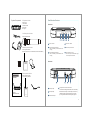
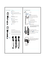
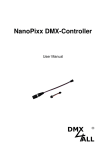
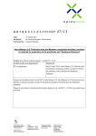
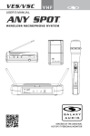
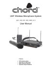
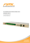
User Manual
A
POWER
B
ANTENNA
AUDIO
NORM
VOLUME
PEAK
MIN
*Bitte informieren Sie sich bei Ihrer lokalen Telekominikationsbehörde.
*Please inform your local Market Surveillance Authorities for Telecommunications.
MAX
MC Crypt Free1
UHF Wireless Series 863-865MHz*
System Components
A
POWER
B
ANTENNA
AUDIO
NORM
VOLUME
PEAK
MIN
All systems include:
Free1 receiver
2 “AA” batteries
A 1/4” RF connector
Power supply
User guide
MAX
Free1 Receiver Features
Front Panel
A
Vocalist system includes:
POWER
B
AUDIO
NORM
ANTENNA
VOLUME
PEAK
MAX
MIN
Free1 handheld transmitter
1
Headset system includes:
Free1 bodypack transmitter
Microphone (choice of PL-10 or PL-20 lavalier,PH-10 or PH-20 headworn)
2
3
4
4 Audio level indicator
2 Channel A antenna LED lamp
5 Audio level peak indicator
When it is steadily lit, Channel A antenna is
working
6 Audio output level control
When it is steadily lit, Channel B antenna is
working
+
-
6
1 Power indicator
3 Channel B antenna LED lamp
+
5
Left turn for output level decrease, right
turn for output level increase.
Rear Panel
Free1
UHF Bodypack Transmitter
D.C.12-18V IN
400mA
Guitar system includes
Free1 bodypack transmitter
1/4” to mini 3-pin guitar cable
User Manual
AF OUTPUT
XLR BALANCED -20dBV
+
1
A
POWER
B
ANTENNA
AUDIO
NORM
1 XLR output jack
VOLUME
PEAK
MIN
MAX
Free1
2 AC adapter jack
MC Crypt Free1
UHF Wireless Series 863-865MHz*
UHF Bodypack Transmitter
1
4 Unbalanced Output
2
3
MUTE LEVEL
UNBAL OUTPUT
3
4
Fine adjustment of mute threshold level
This is the mute enabling threshold value, which is set to factory
default and there is usually no need to adjust it, if there are any
interference signals, this threshold value can be increased
by turning the knob clockwise until RF signal lamp goes out.
2
Handheld Transmitter:
Functions:
Free1 Bodypack Transmitter
1 Microphone head
1
Features:
2 A djust input sensitivity of the m icrophone head
Left turn for sensitivity l decrease, right turn for sensitivity
increase.
1
5
2
4
3
1 Antenna
2 On/Off switch,when it in middle position,mute.
3 RF power switch
Two gain settings are available on Free1 Bodypack
H for high power and L for low power
2
choose the appropriate setting for your instrument
4 Battery compartment
Free1
Mic: microphone
0: Guitar with passive pickups
5 Power/ASC/Battery low indicator light.
3
-10dB: Guitar with active pickups
Green on: power on
Green flash: IR transmission in process.
Red flash: battery low
3 Gain adjustment switch and mute indicator
4 3-pin Microphone Input Jack
6 On-off/mute switch
k
ypac
Bod
U HF
er
smitt
Tran
5 Power/Low indicator light
When turned on, the Battery indicator flashes red and goes
off again. If the battery indicator constantly lights up red , the
batteries should be changed immediately
2
Wearing the Backpack Transmitter:
Changing Batteries:
Expected life for two alkaline batteries is up to 10 hours.
1
When turned on, the Battery indicator flashes red and goes
-
4
off again. If the battery indicator constantly lights up red , the
-
+ +
-
+ +
-
Clip the transmitter to belt 1 , or slide a guitar strap through
the transmitter clip 2 ,as shown.
For best results, slide the transmitter until the belt 1 is
pressed against the base for the clip.
batteries should be changed immediately (as shown below).
5
Changing batteries:
6
Expected life for Two Alkaline batteries is approximately 8 hours.
When the transmitter light glows red, the batteries should be
changed immediately, as shown on the left.
Open
Close
3
4
Trips for improving System Performance
Specifications
Maintain a line of sight between transmitter and antenna.
Avoid placing the receiver near metal surfaces or any digital equipment (CD players, computes, etc)
Keep the receiver away from the wall and over 1m to the ground
Cellular telephones and two-way radio and so on can interfering the transmitting frequencies,
maintain a distance from the interfering equipments or any cause interfering.
Troubles Shooting
Issue
No sound or faint
sound
Indicator Status
Transmitter ON Indicator
stop flashing
Power indicator off
Solution
Turn on transmitter
Make sure the +/- indicator on battery
match the transmitter terminals
Make sure AC adapter is securely
plugged into electrical outlet and into
DC input connector on rear panel of
receiver.
Receiver RF indicator glows
Turn the receiver up
Turn up the Gain adjustment switch in
the transmitter
Check the power connection of the
receiver and amplifier or mixer
Receiver RF indicator off,
transmitter indicator O N
Take the receiver away from the metal
objects
Check whether there is hamper between
receiver and transmitter
Move the transmitter near the receiver
Check the receiver and transmitter
whether use the same frequency
Transmitter low battery
indicator ON
Distortion or
Receiver RF indicator ON
unwanted noise bursts
Change the batteries in transmitter
Remove nearby sources of RF interference(CD players, computers , digital
effects ,in-ear monitor systems, etc.)
System
Frequency Range and Transmitter Output level
Band
UE
Range
Transmitter RF level
838-865 MHz*
10dBm
Sound level different
from cabled guitar or
microphone, or when
using different guitars
5
Transmitter low battery
indicator ON
Change the batteries in transmitter
250mm × 53mm Diameter
Weight
270 grams
Battery Requirements
>10 hours (Alkaline)
60Hz~16KHz
Receiver
Total Harmonic Distortion
( +/- 30 KHz deviation,1 KHz tone)
<1%
Dynamic Range
>90 dB (A –weighted)
Operating Temperature Range
-10 C to +50 C
Note: battery characteristics may limit
the range
Bodypack Transmitter
Audio Input Level Maximum
0 dBV ~+20 dBV
Gain adjustment Range
30 dB
Input Impedance
470 kilohm
2 “AA” alkaline batteries or rechargeable
batteries Battery Life
Audio Output Level Maximum (ref. +/-30 KHz, 1 KHz)
XLR connector (into 600Ω load): -12 dBV
1/4inch connector (into 3000Ω load): -18 dBV
Output Impedance
XLRconnector 200ohm
1/4inch connector 1kilohm
XLR Output
Impedance balanced
Pin 1: Ground
Pin 2: (+)
Pin 3: (-)
Sensitivity (intermediate frequency adjustment
audio noise output <-92 dB)
Image Rejection
> 90 dB
Dimensions
85mm H × 65mm W × 23mm D
235mm H ×118mm W × 44mm D
Weight
80 grams without batteries
Power Requirement
Weight
370 grams
Power Requirements
12-18 Vdc at 400 mA , supplied by external power supply
Battery life
>8 hours (Alkaline)
Adjust transmitter again and receiver
volume as necessary
Audio Input Level maximum
0 dBV
Dimensions (including the microphone)
Operating Range under Typical Condition
50m (150 ft.)
Note: actual range depends on RF signals
absorption,reflection, and interference.
Audio Frequency Response (+/-3 dB)
Two “AA” size alkaline or rechargeable batteries
Distortion level
increases gradually
Handheld Transmitter
* One fixed frequency within 863-865 MHz.
Available frequencies:
863.100 MHz | 863.900 MHz | 864.500 MHz
864.900 MHz
6
Recycling
(Batteries or rechargeable batteries)
The supplied batteries or rechargeable batteries can be recycled. Please dispose of them as special
waste or return them to your specialist dealer. In order to protect the environment, only dispose
exhausted batteries. Together for a good nature.
Safety instructions
No user serviceable parts inside! Never open the transmitter, otherwise you can receive an
electric shock. If units are opened by customers in breach of this instruction, the warranty
Becomes null and void.
Use the transmitter in dry rooms only. Never expose it to water (eg: never place it in a
position where it could be subjected to water splashes). Do not place any objects containing
liquids on the top of the unit.
Keep the transmitter away from direct sunlight, central heating radiators, electric heaters and
similar sources of heat. Ensure sufficient ventilation, especially when it is mounted into a 19”
rack.
Use a damp cloth for cleaning the unit. Do not use any cleansing agents or solvents.
Attention! High Volume!
This is a professional transmission system. Commercial use is subject to the rules and
regulations of the trade association responsible. Adam Hall, as the manufacturer, is therefore
obliged to expressly point our possible health risks arising from use.
Correct Disposal of This Product
(Waste Electrical & Electronic Equipment)
(Applicable in the European Union and other European countries with separate
collection systems)
This system is capable of producing sound pressure exceeding 85 dB (A). 85 dB (A) is the
sound pressure corresponding to the maximum permissible volume which is by law (in some
countries) allowed to affect your hearing for the duration of a working day. It is used as a
basis according to the specifications of industrial medicine. Higher volumes or longer
durations can damage your hearing. At higher volumes, the duration must be shortened in
order to prevent damage. The following are sure signs that you have been subjected to
excessive noise for too long a time:
- You can hear ringing or whistling sounds in your ears.
- You have the impression that you can no longer hear high notes.
Responsible for any content:
Adam Hall GmbH
This marking shown on the product or its literature, indicates that it should not be
Disposed with other household wastes at the end of its working life. To prevent possible
harm to the environment or human health from uncontrolled waste disposal, please
Seperate this from other types of wastes and recycle it responsibly to promote the
sustainable reuse of material resources.
Daimlerstraße 9
D-61267 Neu-Anspach
Phone: +49 (0) 60 81 / 94 19 - 0
Fax: +49 (0) 60 81 / 94 19 - 1000
Geschäftsführer: David Kirby
Register court:
Local Court Bad Homburg v.d.H. HRB Nr. 8076
Household users should contact either the retailer where they purchased this product, or
their local government office, for details of where and how they can take this item for
environmentally safe recycling.
Business users should contact their supplier and check the terms and conditions of the
purchase contract. This product should not be mixed with other commercial wastes for
disposal.
7
Responsible for content according to § 10 paragraph 3 MDStV:
David Kirby
UStId-Nr. DE114114041
WEEE-Reg.-Nr. De55207035
EG-Konformitätserklärung
Diese Geräte entsprechen den grundlegenden Anforderungen und den weiteren Vorgaben der Richtlinien 1999/5/EU, 89/336/EU und
73/23/EU.
CE Declaration of Conformity
This equipment is in compliance with the essential requirement and other relevant provisions of Directives 1999/5/EC, 89/336/ES or
73/23/EC.
8