1
Energywise Technology & UUDM&M Interfacing
U NIVERSITÀ DEGLI STUD I DI C AMERINO
SCUOLA DI ATENEO IN SCIENZE E TECNOLOGIE
Corso di Laurea in Informatica
Dipartimento di Matematica e Informatica
ENERGYWISE TECHNOLOGY &
UUDM&M INTERFACING
________________________________
TECNOLOGIA ENERGYWISE &
INTERFACCIAMENTO AD UUDM&M
Tesi di Laurea Sperimentale
IN PROGRAMMAZIONE E RETI
Laureando
Relatore
Francesco Lilli
Dott. Fausto Marcantoni
Correlatore
DOTT. ING. Mirco Angeletti
ANNO ACCADEMICO 2009 / 2010
1
Table of Contents
2
Energywise Technology & UUDM&M Interfacing
Chapter 1 - Introduction____________________________________ 7
➢______________________________________________________________________ C
ompany issues__________________________________________________ 7
➢______________________________________________________________________ I
P Phones ______________________________________________________ 8
➢______________________________________________________________________ F
amous quotations ______________________________________________ 10
Chapter 2 - Cisco EnergyWise _______________________________ 11
➢______________________________________________________________________ E
W Technology _________________________________________________ 11
➢______________________________________________________________________ E
nergyWise Networks ____________________________________________ 14
➢______________________________________________________________________ E
nergyWise purposes ____________________________________________ 17
➢______________________________________________________________________ L
ayer-based scheme _____________________________________________ 20
➢______________________________________________________________________ W
hy EnergyWise? The Loccioni Group's answer ________________________ 23
Chapter 3 – The project ___________________________________ 25
➢______________________________________________________________________ F
unctional requirements __________________________________________ 25
➢______________________________________________________________________ T
he UUDM&M product, a brief overview ______________________________ 26
Chapter 4 – EW Database __________________________________ 32
➢______________________________________________________________________ P
reamble ______________________________________________________ 32
➢______________________________________________________________________ E
nergyWise Database ___________________________________________ 33
Company __________________________________________________________________ 34
Office _____________________________________________________________________ 35
Department ________________________________________________________________ 36
ImageFloor & ImageArea _____________________________________________________ 39
Switch ____________________________________________________________________ 44
SwitchPort _________________________________________________________________ 45
Event _____________________________________________________________________ 46
SchedulingType _____________________________________________________________ 47
DeviceStatus _______________________________________________________________ 51
SynchronizeMacs ____________________________________________________________ 51
Chapter 5 - EW Client-side Application ________________________ 54
➢______________________________________________________________________ O
verview ______________________________________________________ 54
3
➢______________________________________________________________________ P
HP & Web Server _______________________________________________ 55
➢______________________________________________________________________ A
pplication's Use-Cases ___________________________________________ 60
➢______________________________________________________________________ A
pplication's pages description _____________________________________ 61
login.php __________________________________________________________________ 62
session.php ________________________________________________________________ 63
home.php _________________________________________________________________ 64
services.php _______________________________________________________________ 67
schedule.php _______________________________________________________________ 69
confirm.php ________________________________________________________________ 69
socket.php _________________________________________________________________ 70
gantt.php _________________________________________________________________ 71
➢______________________________________________________________________ C
reation of a Gantt diagram _______________________________________ 72
➢______________________________________________________________________ M
ilestones _____________________________________________________ 73
➢______________________________________________________________________ U
se-Case Descriptions ____________________________________________ 74
➢______________________________________________________________________ S
tate-Chart Diagram _____________________________________________ 77
Cap. 6 – EW Server-side Application _________________________ 81
➢______________________________________________________________________ T
he other side of the Application____________________________________ 81
➢______________________________________________________________________ G
raphs ________________________________________________________ 82
Statistics __________________________________________________________________ 85
➢______________________________________________________________________ M
aps _________________________________________________________ 87
Usage ____________________________________________________________________ 90
➢______________________________________________________________________ S
hut-Down Application ___________________________________________ 91
PsShutDown: Executable _____________________________________________________ 91
PsShutDown: List of Commands ________________________________________________ 92
PsShutDown: Usage _________________________________________________________ 94
Acknoledgements ________________________________________ 98
References _____________________________________________ 98
4
Energywise Technology & UUDM&M Interfacing
Al mare.
5
6
Energywise Technology & UUDM&M Interfacing
7
Chapter 1 - Introduction
Company issues
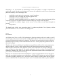
Among the troubles which the entire world's companies have to deal with, the first one is usually
represented by a too high cost to feed the industrial machines.
Reducing the energy consumption of the devices (like routers, switches, computers, modems, etc.)
is not that easy; many device producers are focused on energy savings and make companies prefer
devices of certain brands instead of others. By the way this is often not enough.
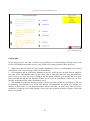
Fig. - The matter of Energy Saving
Let's take companies' telephones as an example (we will see how this thesis is mostly focused on
this kind of devices). Nowadays mobile phones are no more seen as simple vocal communication
devices. Of course they do have communication functionalities, but they also guarantee many
additional features: messages, alarms, reminders, calculators, GPS navigators, even game consoles.
The matter of companies' phones is quite similar: a lot of companies have abandoned the old “just
for calling” telephones to leave the field to the new generation ones, which work like small
computers.
By using these kind of devices we unfortunately occur in some economic disadvantages. The higher
is the complexity of a certain device, the higher are the market costs, as well as its maintenance
costs. Moreover, in order to guarantee all those services (not only telephony), the new generation
phones require electrical power while the old ones only need the network one.
8
Energywise Technology & UUDM&M Interfacing
Obviously, if we just mention the disadvantages of the new phones, it would be impossible to
explain the reason why they are having such a success all around the world. The new generation
phone has actually a lot of advantages also:
•
possibility to send and receive messages, even in broadcast;
•
possibility to save incoming and outcoming phone calls;
•
possibility to create a telephone book;
•
possibility to make DataBase queries, for example if you want to download instantly all the
company's employees telephone numbers without making any storage inside the phone;
•
possibility to visualize images on the screen, or even better to send them through the
network;
•
many others...
The brand leader of this “new generation phone” is without any doubts Cisco Systems, with its
powerful IP Phones. Let's see what we are talking about.
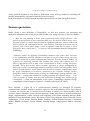
IP Phones
An IP phone uses Voice over IP (VoIP) technologies allowing telephone calls to be made over an IP
network such as the internet instead of the ordinary PSTN system. Calls can traverse the Internet, or
a private IP Network such as that of a company. The phones use control protocols such as Session
Initiation Protocol, Skinny Client Control Protocol or one of various proprietary protocols such as
that used by Skype.
Thanks to the Internet capillarity, it is possible to merge different offices of the same company in a
unique telephonic system: a single station allowing the interconnection between employees in
different offices around the world. IP Phone systems assure important cost savings by unifying
voice and data in a unique network. The system maintenance can be even done in a centralized way;
furthermore, thanks to the VoIP services which offer important discounts on the normal phone fees,
you can have an efficient line rental saving.
IP phones can be simple software-based Softphones or purpose-built hardware devices that appear
much like an ordinary telephone or a cordless phone. Ordinary PSTN phones are used as IP phones
with analog telephony adapters (ATA). It may have many features an analog phone doesn't support,
such as e-mail-like IDs for contacts that may be easier to remember than names or phone numbers.
9
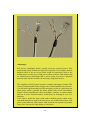
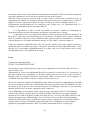
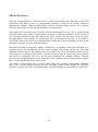
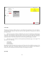
Fig. – Cisco 7940 Series IP Phone
IP Phones consume today an average of 5 W (Watt), at full energy. This is nothing compared to the
average consumption of a normal computer: around 70 W (or even much more, if we consider the
most powerful machines).
Let's consider now a big company, which counts more than 1000 employees. Assuming that each
employee of this company has a telephone and a computer, the energy consumption that we daily
obtain is, at this point:
[ ( Single Telephone Consumption + Single Computer Consumption) * Nr. of Employees ] * Daily Work Hours =
[ ( 5 + 70 ) * 1000 ] * 24 = 1.800.000 Wh.
We can also round up the above proposed figure to 2.000.000 Wh, taking into account that a big
company (which makes a large use of computer networks) usually needs further devices, like
switches and routers: they absorb something like 130 W, which is really much.
There's no doubt that an amount like this, 2.000.000 Wh, attracts more attention. Let's see now how
much would be the consumption if we apply intelligent (or “wise”) policies.
Let's assume the following scenario: the working hours of a company are 10, even considering the
eventual extra-working time of some employees. This company, using the phones just for as long as
necessary (8 hours per day), would consume as following:
Single Phone Consumption * Nr. of Employees * Daily Work Hours Telephones +
Single Computer Consumption * Nr. Of Employees * Daily Work Hours Computers =
5 * 1000 * 8 + 70 * 1000 * 24 = 120.000 + 1.680.000 = 1.720.000 Wh.
So we would obtain a difference of 80.000 Wh daily consumed, only switching off the phones
(which represent the less-expensive devices for the energy consumption) when not necessary, with a
4.5% of energy savings.
10
Energywise Technology & UUDM&M Interfacing
At this point the question is: why don't we think about a new and easy method of switching off possibly automatically- the phones when they're not necessary?
In the next chapter we will go through the subject and will discover what EnergyWise means.
Famous quotations
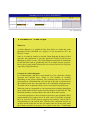
Before giving a clear definition of EnergyWise, we will now mention two interesting and
explicative quotations; this would give an idea of what we're going to discuss in the next chapters.
« “How are you planning to make your organization more energy efficient?” The
answer to that question is more important than ever. You need to reduce energy costs.
You must prepare to comply with government regulations and laws, and you want to do
what's right for the environment and for your business. You need an accurate way to
measure your current power usage, a way to regulate it and also to report it. Cisco
Energywise does exactly that. […] » (from a Cisco presentation about the EnergyWise
technology)
« Business leaders are defining sustainability initiatives that reduce their electrical
power consumption and CO2 emissions in an effort to not only reduce energy costs, but
to also be respectful of global environmental concerns. To assist business leaders, IT
suppliers are delivering products that consume less energy while offering new IT
delivery approaches such as data center virtualization to reduce cooling and power
demands. Cisco Systems has taken a broader approach to energy management by
delivering a power command and control architecture called Cisco EnergyWise which
seeks to provide business and IT leaders with the tools to measure, manage and control
the power consumption of all devices connected to the corporate network. Further,
EnergyWise seeks to connect facility heating, air conditioning, lighting and other nonIT systems — systems that consume the largest proportion of corporate energy — in an
effort to provide IT leaders with the tools and means to manage their overall energy
consumption. » (from the introduction of the report “Controlling Corporate Energy
Consumption via the Enterprise Network”, Nicholas John Lippis III, 2009)
Note: Nicholas J. Lippis III is a world-renowned authority on advanced IP networks,
communications and their benefits to business objectives. He is the publisher of The Lippis Report,
a resource for network and IT business decision leaders to which over 40,000 business and IT
executive leaders subscribe. He has advised numerous Global 2000 firms on network architecture,
design, implementation, vendor selection and budgeting, with clients including Barclays Bank,
Microsoft, Kaiser Permanente, Sprint, Worldcom, Cigitel, Cisco Systems, Nortel Networks, Lucent
Technologies, 3Com, Avaya, Eastman Kodak Company, Federal Deposit Insurance Corporation
(FDIC), Hughes Aerospace, Liberty Mutual, Schering-Plough, Camp Dresser McKee and many
others.
11
Chapter 2 - Cisco EnergyWise
EW Technology
Cisco EnergyWise is an innovative technology presented by Cisco in January 2009 during the
prestigious “Networkers”, an event known all over the world for the modernity and the importance
of its treated topics. EnergyWise allows to automatize the energy regulation on various types of IP
devices, by using the PoE technology (see Document 1.X, “Power over Ethernet (PoE)”). The
technology encompasses a highly intelligent network-based approach to communicate messages
that measure and control energy between network devices and endpoints. The network discovers
Cisco EnergyWise manageable devices, monitors their power consumption, and takes action based
on business rules to reduce power consumption. EnergyWise uses a unique domain-naming system
to query and summarize information from large sets of devices, making it simpler than traditional
network management capabilities. Cisco EnergyWise’s management interfaces allow facilities and
network management applications to communicate with endpoints and each other using the network
as a unifying fabric. The management interface uses standard SNMP or SSL to integrate Cisco and
third-party management systems.
Fig. - Cisco logo
Conventional wisdom is that datacenters are the epicentre of Green IT initiatives as they are large
centralized energy consumption footprints. Their centralization affords ease of access to control
energy consumption. But there is far more energy consumed, over 90%, throughout a corporation
than in its datacenter. The network sprawls the entire organization from headquarters to regional
sites to manufacturing floors to branch offices, affording it access to control this larger energy
consumption footprint and put power management under the control of IT. Cisco EnergyWise adds
power management value by tackling the sprawl issue.
For example consider a 48-port switch that on average may connect 10 PoE phones, 10 WLAN APs
and perhaps 20 PCs. Adding up the power consumed by all of these devices, a 48-port switch has
the opportunity to manage and control some 6-7,000 watts of power or between 125-to-145 watts
per port. For an organization with 10,000 IP devices connected into their network, a Cisco
EnergyWise-empowered network has the opportunity to manage 1.45 million watts of power. This
number increases significantly as non-IP building control systems are Cisco EnergyWise-enabled.
12
Energywise Technology & UUDM&M Interfacing
In effect, a network switch is not only managing IP traffic, but also energy consumed by connected
devices.
▼ Document I : Power over Ethernet (PoE)
What it is
Power over Ethernet (standard IEEE 802.3af) is the ability for the LAN
switching infrastructure to provide power over a copper Ethernet cable to
an endpoint (Powered Device). This capability, once referred to as “inline
power”, was originally developed and first delivered by Cisco in 2000 to
support the emerging IP Telephony deployments. IP Telephones, like
desktop PBX phones, need power for their operation and Power over
Ethernet enables scalable and manageable power delivery and simplifies
deployments of IP Telephony. As Wireless networking emerged, Power
over Ethernet was also used to power these devices to allow for
deployments in locations where local power access did not exist. While IP
telephones and wireless access points are the most intuitive uses for PoE,
the advent of 802.3af standardization of PoE opens the door to a new
generation of networked-attached devices such as video cameras, point-ofsale devices, security access control (card scanners), building automation
and industrial automation just to name a few.
PoE's working principle is really simple. Ethernet and Fast Ethernet cables
consist in four pairs of wires, where two couples are used for data
transmission and the other two couples are used for the power transmission.
Fig.XX is showing two normal Ethernet cables with RJ-45 connectors: the
external wires (the ones which are not inside the connector) are those
needed for the power transmission. All the features of PoE devices are
specified in the IEEE 802.3af standard.
Cisco offers a comprehensive range of 802.3af-based Power over Ethernet
support across its Catalyst Intelligent Switching portfolio. Additionally,
Cisco Catalyst Intelligent Switches deliver Intelligent Power Management
capabilities beyond the optional IEEE Power Classification feature to
enable granular, optimized and scalable power delivery for more efficient
power management and prioritization of power delivery.
Power over Ethernet (PoE) promises to create a new world of networked
appliances by providing power as well as data connectivity over existing
Ethernet cables.
13
Fig. - Ethernet cables with RJ-45 connectors
Advantages
PoE devices installation doesn’t usually need any electrical power. This
means being totally flexible and often less expensive. For example, the best
position where to put an Access Point would be somewhere close to the
ceiling where it is not easy to find power points (sockets). This implies that
we would need to build and cable a power point, as well as a physical
network cable. All this wouldn’t be necessary using PoE devices.
The simplicity of PoE electric structure is another advantage. If under UPS
control (Uninterruptible Power Supply, also Uninterruptible Power Source,
is an electrical apparatus that provides emergency power to a load when the
input power source, typically the utility mains, fails) a PoE surveillance
system, which comprehends video surveillance cameras, a control station
and one or more switches/routers, would keep on working in case of a
blackout.
If we want to obtain the same result with an hybrid system, which works
with both networks as well as electric power, we would need to place each
power point under the UPS control. That would be an expensive operation
in any case, because the only things we can do are:
14
Energywise Technology & UUDM&M Interfacing
•
•
to dislocate the UPS apparatus (which is usually of huge
dimensions) and put it close to the devices, or
to cable a dedicated electric line.
Conversion kits
All non-PoE existing apparatuses can take advantage of this technology
through a special conversion kit. The kit is composed by a pair of parts:
•
The injector at the starting point has a very important task: to add
the electric power, 48V DC standard, to the free wires couples.
The injector has a link to the electric network and two LAN
sockets: one of these is for the cable which comes from the
switch/router/hub or whatever point of the network, depending on
the equipment; the other one is for the cable which has to be
connected with the final device.
•
The splitter (or picker) has to separate the power supply from the
network cable. The splitter has two sockets as well: one is for the
cable which comes from the injector, and the other one is for the
connection with the non-PoE device. It also has got a connector
from where it takes the electric power, added by the injector.
Two types of picker exist, active and passive. In the first one the voltage
which comes from the injector is tuned according to the characteristics of
the device that has to be powered. The peculiarity of this type of picker is
that the incoming voltage is transformed in a new one, which is one of the
standards 12V, 6V or 5V DC. In a passive picker the outgoing voltage has
the same value as the voltage inserted by the injector.
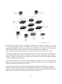
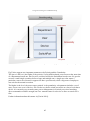
EnergyWise Networks
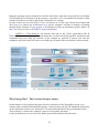
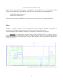
A typical EnergyWise network can be represented as in Fig. X, where:
•
type “1” devices are Management Stations, typically Server stations which send requests and
set parameters using the EnergyWise protocols;
•
type “2” devices are Domain Members, intelligent devices which define the domain where
we're operating on, like switches and routers. A domain is treated as one unit of power management
and is similar to a network-management community;
•
type “3” devices are End Points, which typically are simple client machines such as terminal
PCs, Access Points, IP Phones (even connected each other).
15
Fig. – EnergyWise Network
By observing the scheme of a normal computer network, and comparing it with the one in Fig.X,
we won't find anything different or anomalous. The difference resides in the required protocols
support for EnergyWise, owned today only by some switches of the “Catalyst” series and by few
Cisco IP Phones. The tables X and Y report the devices that support the technology.
What make these switch models “special” is the particular IOS version which resides in them.
Cisco IOS (originally Internetwork Operating System) is the software used on the vast majority of
Cisco Systems routers and current Cisco network switches (earlier switches ran CatOS). IOS is a
package of routing, switching, internetworking and telecommunications functions tightly integrated
with a multitasking operating system.
IOS versions older than 12.2 do not provide EnergyWise support; for a correct functioning and
behavior, the switches listed in Table X require an IOS 12.2(52)SE release or an even bigger one
and the EnergyWise Specification version 0.6n.
It is important to underline that devices with EnergyWise support don't compromise their usual
functions. In other words, EnergyWise and not-EnergyWise switches can live together without any
problems. All EW management requests will be understood, interpreted and replied by EW switches
while the other switches will not understand what they are asked to do.
16
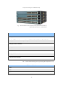
Energywise Technology & UUDM&M Interfacing
Fig. – Various models of Cisco Catalyst. From top to bottom: 2960-24TC-L;
3560E-24PD; 2960-48TC-L; 3560E-48PD-E.
Switch Model
Catalyst 3750-E switches
Catalyst 3750 switches except Catalyst 3750G-24WS, 3750G-16TD, 3750V2
Catalyst 3560-E switches
Catalyst 3560 switches
Catalyst 2975 switches
Catalyst 2960 switches
Catalyst 2918 switches
Tab. – Switch which offer EnergyWise support (EnergyWise Specification 0.6.n)
IP Phone Model
7906
7911
7912
7940
17
7960
7970
...
Tab. – Some IP Phones which offer EnergyWise support
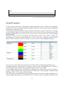
EnergyWise purposes
So far we had a quite unclear description of what EnergyWise really is. What does EnergyWise
actually do? We have just explained that EnergyWise allows the users to make energy management
but what does it means exactly?
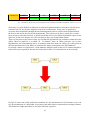
It means that it's literally possible to choose the power level that we want a certain device to assume
in a well-defined instant, in a scale from the value 0 to the value 10. You can remotely switch off a
telephone (which means to set its level to 0), you can give it a full (level 10) or an intermediate
level of energy.
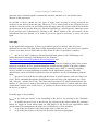
In Fig.XX we can see how Cisco Sistems has defined the operative mode (“Mode” column), the
representing color and the relative RGB code (“Color” and “Code” columns), and the univocal
name (“Label” column) of each level, valid for every Cisco device with EnergyWise support.
Fig. – Category and Power Level table
Up to now you cannot find on the market any new kind of device managing intermediate states.
Companies that have just started (or are going to start) to work on EnergyWise were assured by
Cisco Systems that new phone models with this feature will be soon available.
In the meantime IOS provides commands for switching off-on remote devices; more in details, if
we give a Shut command (zero energy, 0) the device shuts down, while all higher commands (from
Hibernate to Full, 1..10) switch it on at full energy.
One of the most powerful and interesting operations which can be done by using EnergyWise is to
send scheduling instructions to switches and routers. In other words it's possible to dictate definite
18
Energywise Technology & UUDM&M Interfacing
schedules which the network devices have to follow. For instance, if we want to switch on an IP
telephone at 8:00 in the morning and then to shut it down at 7:00 in the afternoon (as it usually
happens in many factories) every weekday, we just have to write the appropriate code and run the
command. That's all.
With a simple energy policy of shutting down devices for some hours a day, a company will gain
significant power usage savings. In essence, Cisco EnergyWise can utilize the network to act as a
distributed programmable thermostat changing the power consumption of devices and business
control systems based on time of day. The network keeps time and thus can be the timer for
connected devices.
Consider a 5,000-employee business all equipped with IP phones and 500 WLAN APs. By simply
powering down IP phones and WLAN AP for ten hours per evening plus holidays and weekends,
this firm would save some 40000€ per year by reducing their electrical energy consumption by
423,500kW, assuming 0.12€ per kWh. That is the CO2 equivalent of planting 200,000 trees or
preventing some 12,000 mid-size automobiles from emitting annual emissions into the atmosphere.
The cost and CO2 savings increases significantly as non-PoE and non-IT devices become Cisco
EnergyWise compliant, since IP Phones and WLAN AP represent less than 2% of total corporate
energy consumption.
Let's see in the following table (Tab.XX) some of the most important and interesting IOS
commands and functions (O.S. versions ≥ 12.2).
For a more specific and complete discussion of the EnergyWise commands have a look on the link
http://www.ciscosystems.com/en/US/docs/switches/lan/energywise/phase2/ios/configuration/guide/
ew_v2.pdf, the complete Cisco-developed guide for generic EnergyWise configurations.
Command
show energywise
Purpose
Verifies the entries.
energywise domain domain-name secret [0 | 7] Enables EnergyWise on the entity, assigns the
password [protocol udp port udp-port-number entity to a domain with the specified domain[interface interface-id | ip ip-address]]
name and sets the password for secure
communication among the entities in the
domain.
secret → 0 stands for unencrypted password
(default), 7 means hidden password.
port → specifies the UDP port that sends and
and receives queries.
interface → specifies the port from which the
EnergyWise messages are sent.
ip → specifies th IP address from which the
EnergyWise messages are sent.
copy running-config startup-config
Saves the new entries in the configuration file.
energywise management udp-port-number
Specifies the UDP port that sends and receive
queries. The range is from 1 to 65000, the
default is 43400.
19
energywise level level
Manually sets the level of the port.
energywise level level recurrence importance Schedules the recurrences.
importance at minute hour day_of_month month importance → sets the importance of the port in
day_of_week
the domain. The range is from 1 to 100, the
default is 1.
minute → the range is from 0 to 59. Use * for
the wildcard.
hour → the range is from 0 to 23. Use * for the
wildcard.
day_of_month → the range is from 1 to 31. Use
* for the wildcard.
month → the range is from 1 to 12. Use * for
the wildcard.
day_of_week → the range is from 0 (Sunday) to
6 (Saturday). Use * for the wildcard.
energywise query importance importance
Runs a query to display power information for
{keywords word,word,...| name name}{collect | the domain entities and PoE ports.
sum} {delta | usage}
importance → filters the result based on the
importance value. Only entities with values less
than or equal to the specific value appear.
keywords → filters the result based on one or
more of the specified keywords.
name → filters the result based on the name.
collect → simply display the delta or usage
values for the entities and PoE ports.
sum → display the sum of the delta or usage
values for the entities and PoE ports.
delta → the difference between the current and
available power usage.
usage → the current power usage.
energywise query importance importance
Runs a query to power on or power off the
{keywords word,word,...| name name}set level domain entities or PoE ports.
level
Everything like above but this:
set level → set the power level of th entities or
PoE ports. The range is from 0 to 10.
no energywise interface configuration
Disables EnergyWise on the PoE port.
show energywise {children | domain | events | Verifies particular details about the entries.
children → the status of the entity and the PoE
neighbors | recurrences | statistics | usage |
version}
ports in the domain.
domain → the domain to which the entity
belongs.
events → the last 10 events (messages) sent to
other entities in the domain.
neighbors(*) → the neighbor tables for the
domains to which the entity belongs.
20
Energywise Technology & UUDM&M Interfacing
recurrences → the EnergyWise settings and
status for recurrence.
statistics → the counters for events and errors.
usage → the current power usage on the entity.
version → the current EnergyWise version.
(*) Between entities are neighbors. Two switches in a network
could be neighbors. The neighbor relationship is designed for
clearing the sending command and control messages while the
parent and child entities are designed to control power.
Tab. – Some of the EnergyWise commands and relative explanations, provided by the newest versions of Cisco IOS
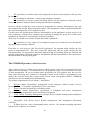
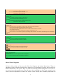
Layer-based scheme
The figure below (Fig.X) proposes a layer-based scheme which represents how the EnergyWise
applications work inside a network. Very similarly to the famous ISO/OSI model, which provides 7
layers, and to the as much famous and important Internet model, which provides 5 layers, in this
case we essentially have to deal with the following four layers:
•
LAYER 3 - Management Applications: the EnergyWise network monitoring and managing
applications, generally executed on a Server machine.
Essentially we have two kinds of applications:
1.
First-Party Applications: programs provided, or authorized, by the company that distributes
the base software. We're talking about Cisco Systems developed and distributed program, to exploit
EnergyWise advantages;
2.
Third-Party Applications: programs which are written by individuals or companies other
than the provider of the basic software.
Nowadays we cannot find a lot of third-party applications on the IT market. Only few
companies in the world believe on the advantages that the research on the EnergyWise,
which implies important investments, could bring. We will come back to this further on.
•
LAYER 2 – Management APIs: those Application Programming Interfaces that are used for
controlling and managing the energy levels of the network devices. The Management APIs offer
access to entire domains to pull power consumption and device efficiency information as well as
location.
We will not go in detail though APIs matters; an extensive discussion of everything you would like
to know about is treated in [Uncini, 2010].
•
LAYER 1 – Network Software: all the kinds of software that runs on the network devices
which offer EnergyWise support. With the “software” term we mean, more properly, the operating
system (O.S.) which runs on these devices; like we already said, the EnergyWise technology is
implemented on IOS operating systems from the version 12.2.
21
Being an operating system designed for switches and routers, IOS does not provide an user-fiendly
GUI (Graphical User Interface); on the contrary, it provides a CLI (Command-Line Interface) from
which it's possible to set and to edit all the existing device's settings.
In order to have access to the IOS's CLI we can operate in several ways, but the most simple and
direct one is to connect the switch/router to a generic computer, and then to manage everything
through Hyper-Terminal. If you are new to this handy tool take an introductory glance about it at
http://www.avitresearch.co.uk/USBTTL/hyperterminal.htm.
•
LAYER 0 – Client Software: the software that runs on the “client” apparatuses (like IP
Phones, IP Cameras, computers, etc.) that allows the execution on the EnergyWise instructions and
commands that come from the network. At the moment it's possible to operate just with the
telephones specified in the Tab.X above and with some IP-based video surveillance camera models.
Fig. – Layer-based scheme of the EnergyWise applications' functioning inside the networks
Why EnergyWise? The Loccioni Group's answer
In this chapter we had a general but quite effective description of the EnergyWise world, even
without using a technical and detailed language. Curious readers can have all additional information
on the mentioned websites (see “References” section) which this thesis has got information from.
That would give a much more exhaustive answer to all possible questions.
At the moment there's no need at all for further general informations about the topic.
22
Energywise Technology & UUDM&M Interfacing
Subjects like energy consumption, often excessive, have been widely discussed for a long time and
the application of smart scheduling policies is certainly the answer to:
•
•
the increase of greenhouse gases, produced by the Man's hand;
the increase of production costs for the companies.
All the characteristics, the qualities and the advantages that a company could get by following
EnergyWise policies have interested many companies.
In particular we would like to talk about the Italian Loccioni Group (http://www.loccioni.com),
historical Cisco partner for telecommunication and network fields, a company with three branch
offices in the Marche region. Here is an article published by “Il Sole 24 Ore”, dated 23 December
2009:
http://www.loccioni.com/Portal/Uploads/rassegna%20stampa/2009/IL%20SOLE%2024%20ORE_P
RIMA%20PAGINA_%20231209.pdf. The second page of the newspaper is entirely dedicated to
Enrico Loccioni, the Loccioni Group founder.
“Il Sole 24 Ore” is an important Italian national daily business newspaper owned by Confindustria,
the Italian employers' federation. It reports on business, politics, developments in commercial and
labour law, corporate news and features. Website: http://www.ilsole24ore.com/.
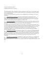
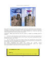
Fig. - The article about Loccioni Group, Il Sole 24 Ore 23 /12/2009. In the main photo E. Loccioni
Since January 2009 the marketing managers of the company have been fascinated by this new
technology. Mirco Angeletti, Loccioni Group's marketing manager at Moie office (AN), explains as
follows the reasons for such a big interest on the topic:
23
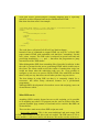
« Nowadays the energy consumption monitoring is becoming
Fig. - Mirco
Angeletti
more and more important even for the enterprises. Immediate
consequence of that is the research of the areas with the highest
percentage of power absorption inside the enterprises, such as
the datacenter, thermal installations and lastly (but not in
importance order) the desktop equipment, e.g. all the technical
equipment normally related to the “workspaces”, where we
estimated an average consumption of 70 Watt per user,
independently on the users' activities. Thanks to the data
network, by this time present in all the production activities, we
can even monitor the user's and his equipment's state, and
intervene on the power management if needed. » (M. Angeletti)
Encouraged by the fact that just few other companies decided to invest on the EnergyWise project,
being this in a not-so-mature phase, the Loccioni Group has decided to leave the development of an
application program for functionalities tests to two internship students. The two individual in
question are the undersigned and Michel Uncini, both Computer Science Technology students at the
University of Camerino (http://www.unicam.it/), Department of Mathematics and Computer
Science. The undersigned wrote this hopefully interesting thesis, while the other wrote the
excellent thesis/manual “UUDM&M (Unified User Device Management & Monitoring), Modulo
SNMP & IP Phone Services ” [Uncini, 2010]. In the following chapters we will mention and
redirect on the argument treated on Michel's thesis, since it goes through many details which are not
treated in here.
24
Energywise Technology & UUDM&M Interfacing
Fig. - The short article published on people.loccioni.com
Chapter 3 – The project
Functional requirements
At the beginning Loccioni Group's idea was to develop a completely manageable EW platform,
designed just for network administrators (so it would have been just a Server-side application). The
platform should have provided an user-friendly graphical interface (GUI), conversely from the
command-line interface (CLI) already provided by IOS, in order to make the company's IP phones
management be easier and faster. As an indication, the main Server-side application's functional
requirements were, at the beginning:
•
R1: windows-based graphical interface, to be preferably developed using WPF Graphical
Subsystem to (see Document 1.X);
•
R2: possibility to manage the Loccioni network in its entirety, which means to manage more
offices together (in particular, the Loccioni network is used by Moie (AN) and Angeli di Rosora
(AN) offices );
25
•
R3: possibility to visualize and easily manage the locations of the telephones directly from
the interface;
•
R4: possibility to shut down / switch on the telephones instantly;
•
R5: possibility to execute certain scheduling policies on the telephones following various
criteria, for instance employee-based and department-based scheduling.
However, all this would have been exclusively manageable by network administrators, the only
ones authorized to modify highly important settings. The consequence is that an application like this
one could be designed for server apparatuses only.
For this reason we decided then to add new functionalities to the application, in order to give to all
users (employees working in the company) the possibility to manage the power level of their own
telephones by themselves, and setting the associated schedules.
That's why we should now consider another functional requirement:
•
R6: possibility of every single user to manage the power level of their devices, through the
already-existing company's Intranet.
From now on, we're going to call “Server-side Application” the program which satisfies the first
group of requirements (R1 .. R5), and “Client-side Application” the one which satisfies the last
requirement (R6). It's important to understand right now that we're talking about two different and
separate applications, with distinct purposes and partially different functionalities, that cooperate for
the achievement of the proposed goals.
The UUDM&M product, a brief overview
After a short period of working on the project (which means on the Server-side and Client-side
applications development), we realized that Cisco IP telephones offer a lot of possibilities in terms
of their management. We are not talking about possibilities for EW purposes only but even for
many other interesting ones. Thanks to a thorough research on the subject, a programmers work
team of the Loccioni Group have created a first version of the total product, named UUDM&M
(Unified User Device Management & Monitoring).
The product comprehends several “blocks”, listed below:
1.
Records (italian: Anagrafiche): management of the company's “address books”, devices
inventory, “User → Company's Organization Chart” association.
2.
Totem: collection and analysis of telephonic paths.
3.
Reporting (italian: Reportistica): presentation of telephonic and power consumption
information, using customizable reports and Intranet integration.
4.
UTM, Unified Telephony Management: package for the complete management of telephonic
devices, constituted by two parts:
•
EnergyWise: PoE devices' power profiles management, and consumption information
collection.
•
IP Phone Services: suite of manageable phone services, like instant messaging and phone
calls between computers in a network.
26
Energywise Technology & UUDM&M Interfacing
The initial project at this point has been extended: firstly we just had to deal with the “EnergyWise”
section, but now the Uncini-Lilli project can be seen as the sum of the “EnergyWise” and the “IP
Phone Services” section, which is called UTM.
The project we're going to analyse is this one, UTM. In particular, in this thesis we're going to
explore half of the “EnergyWise” section, which is the Client-side Application.
By the way, speaking of the UTM project in its entirety, another functional requirement should be
added to the ones we already talked about:
•
R7: possibility to administrate a messaging service and internal phone calls directly through
the companies' computers, making use of and user-friendly and Skype-like interface.
Note that this service is not included in the “EnergyWise” section, as we're talking about the second
point, “IP Phone Services”. However the service is closely related to the EnergyWise section: if we
run the UTM application in a server machine it should be possible to call the general section “IP
Phone Services” directly from the “EnergyWise” section (not vice versa: at least in this first version
the first section cannot run without the second one). These services should work together and help
each other if needed, as a unique application.
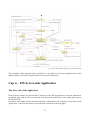
In the following figure (Fig.X) is shown an high-level scheme of the UUDM&M structure.
In this thesis we will not go into the details of the UUDM&M product, since our intention is just to
build a small portion if the entire system which could communicate with all the provided services.
For further information about this brand new product can be found in [Uncini 2010].
So now let's tell clearly what will be presented in this thesis later on. In particular we will try to go
through the following aspects:
•
EnergyWise's Database block, which is an important component of the section, and
everything concerning it (Chapter 4);
•
Client-side Application, which relies on the company' Intranet (Chapter 5);
•
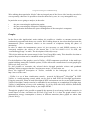
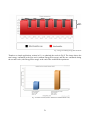
Demonstration graphs, through which we have measured in practice the energy savings due
to the application of EnergyWise policies (Chapter 6);
•
Company's mapping system (Chapter 6);
•
Small application for the company's PCs power management (Chapter 6).
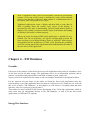
▼ Document II : WPF
27
What it is
The Windows Presentation Foundation (or WPF) is a graphical subsystem
for rendering user interfaces in Windows-based applications. WPF,
previously known as "Avalon", was initially released as part of .NET
Framework 3.0. Designed to remove dependencies on the aging GDI
subsystem, WPF is built on DirectX, which provides hardware acceleration
and enables modern UI features like transparency, gradients, and
transforms.
Windows Presentation Foundation (WPF) provides developers with a
unified programming model for building rich Windows smart client user
experiences that incorporate UI, media, and documents.
It is a next-generation presentation system for building Windows client
applications with visually stunning user experiences. With WPF,
programmers can create a wide range of both standalone and browserhosted applications; it provides a consistent programming model for
building applications, and a clear separation between the user interface and
the business logic.
The core of WPF is a resolution-independent and vector-based rendering
engine that is built to take advantage of modern graphics hardware. WPF
extends the core with a comprehensive set of application-development
features that include Extensible Application Markup Language (XAML),
controls, data binding, layout, 2-D and 3-D graphics, animation, styles,
templates, documents, media, text, and typography.
WPF is included with Windows 7, Windows Vista, and Windows Server
2008 and is also available for Windows XP Service Pack 2 or later
versions, and Windows Server 2003.
Windows Presentation Foundation (WPF) supports the creation of the
following types of applications:
•
Standalone Applications (traditional style Windows applications built as
executable assemblies that are installed to and run from the client machine).
•
XAML browser applications (XBAPs) (applications composed of navigable
pages that are built as executable assemblies that are browsed to and hosted by
Windows Internet Explorer).
•
Custom Control Libraries (non-executable assemblies containing reusable
controls).
•
Class Libraries (non-executable assemblies that contain reusable classes).
Note: The use of WPF to build Windows services is unsupported. Because
WPF is a presentation technology, the Windows service requires the
appropriate permissions to perform visual operations that involve user
interaction. If the Windows service does not have the appropriate
permissions, there may be unexpected results.
28
Energywise Technology & UUDM&M Interfacing
Users interact with WPF standalone applications through windows. The
purpose of a window is to host application content and expose application
functionality that usually allows users to interact with the content. In WPF,
windows are encapsulated by the Window class, which supports:
Creating and showing windows.
Establishing owner/owned window relationships.
Configuring window appearance (for example, size, location, icons, title
bar text, border).
Tracking and interacting with the lifetime of a window.
XAML
Extensible Application Markup Language (XAML) is a markup language
for declarative application programming. XAML files are XML files that
generally have the .xaml extension; WPF implements a XAML loader and
provides XAML language support for WPF types such that you can create
the majority of your application UI in this markup. In addition, the SDK
includes a XAML editing tool called XAMLPad. You can use this tool to
experiment with XAML in real time.
The ability to mix code with markup in XAML is important because XML
by itself is declarative, and does not really suggest a model for flow
control. An XML based declarative language is very intuitive for creating
interfaces ranging from prototype to production, especially for people with
a background in web design and technologies. Unlike most other markup
languages, XAML directly represents the instantiation of managed objects.
This general design principle enables simplified code and debugging
access for objects that are created in XAML.
An important aspect of XAML is the code-behind. “Code-behind” is a
term used to describe the code that is joined with the code that is created
by a XAML processor when a XAML page is compiled into an
application.
The following XAML example shows how little markup is necessary to
create a button as part of a UI. The created button has default visual
presentation through theme styles, and default behaviours through its class
design.
<StackPanel>
<Button Content="Click Me"/>
</StackPanel>
Summary
29
WPF is designed to allow you to create dynamic, data driven presentation
systems. Every part of the system is designed to create objects through
property sets that drive behaviour. Data binding is a fundamental part of
the system, and is integrated at every layer.
Traditional applications create a display and then bind to some data. In
WPF, everything about the control, every aspect of the display, is
generated by some type of data binding. The text found inside a button is
displayed by creating a composed control inside of the button and binding
its display to the button’s content property.
When you begin developing WPF based applications, it should feel very
familiar. You can set properties, use objects, and data bind in much the
same way that you can using Windows Forms or ASP.NET. With a deeper
investigation into the architecture of WPF, you'll find that the possibility
exists for creating much richer applications that fundamentally treat data as
the core driver of the application.
Chapter 4 – EW Database
Preamble
Like most of the software of this kind, the Server-side Application also needs for a database, since
it's the best tool for the data storage. The application uses a lot of information and data, and in
practice it would be totally impossible to deal with it without a good “supervisor”.
Anyway, later we'll explain how the usage of only one database would not be an optimal solution.
For the moment let's just focus on the tables on which the Server-side Application takes the
concerned data, even if the application does not make an exclusive use of it. From now on, we'll call
this series of tables “EW Database”; in this chapter we will discover everything about this data
structure, since we're going to go deeply into it.
These tables are also essential for the correct functioning of the Client-side Application, which in
some cases asks for information directly to the EW Database, as well as to the Server-side
Application via UDP and TCP requests.
EnergyWise Database
30
Energywise Technology & UUDM&M Interfacing
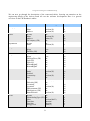
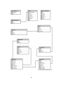
We can now go through the description of the concerned tables, focusing our attention on the
engineering details of the choices made all over the software development. Here is a general
overview on the EW Database's tables:
Table
Column Name
Data Type
Allow Nulls
Company
Id (PK)
Name
Address
int
varchar(50)
varchar(50)
no
yes
Office
Id (PK)
Name
Address
FkCompany (FK)
int
varchar(50)
nchar(50)
int
no
yes
yes
Department
Id (PK)
Name
int
varchar(50)
no
ImageFloor
Id (PK)
Image
FkOffice (FK)
int
text
int
yes
yes
ImageArea
Id (PK)
Image
FkImageFloor (FK)
TopLeftX
TopLeftY
BottomRightX
BottomRightY
int
text
int
int
int
int
int
yes
yes
yes
yes
yes
yes
Switch
IP (PK)
Name
Enabled
Community
Port
varchar(20)
varchar(50)
bit
varchar(50)
int
yes
no
no
no
SwitchPort
IndexPort (PK)
FkSwitch (PK)
LocationX
LocationY
FkDepartment (FK)
FkImageArea (FK)
NameInSwitch
varchar(50)
int
int
varchar(20)
int
int
varchar(50)
yes
yes
yes
yes
yes
Event
Id (PK)
FkSchedulingType (FK)
Value
TimeStart
TimeStop
EnergyLevel
int
int
varchar(MAX)
datetime
datetime
nchar(2)
no
no
no
no
no
31
Disabled
bit
no
SchedulingType
Id (PK)
Name
int
nvarchar(50)
no
DeviceStatus
MacAddress (PK)
Status
varchar(MAX)
smallint
no
SynchronizeMacs
Id (PK)
OldMac
NewMac
IndexPort
SwitchIP
Name
int
vachar(50)
vachar(50)
nvachar(50)
nvachar(50)
nvachar(50)
no
no
no
no
no
Tab. – EnergyWise Database tables scheme
Now we are going to analyze the table descriptions, one by one.
We are not going to go through the fundamental principles which stand at the basis of the Databases
theory, because it would be totally out of the intentions of this thesis. That's why we are not going to
explain in a very exhaustive way all the dependences between the tables, assuming that the reader
already has a basic knowledge of database's management. The mnemonic names which have been
chosen for tables and fields should make the understanding easier and faster. For an exhaustive
guide
for
the
databases
management,
we
propose
an
optimal
website:
http://infolab.stanford.edu/~ullman/dscb.html#projects.
Company
Connections with other tables:
COMPANY 1:N OFFICE
This table consists on the list of the companies to be considered. Let's keep in mind that the UTM
Application is designed for the complete management (EnergyWise + IP Phone Services) of generic
companies, and not only of the Loccioni Group where we operated during the writing of this thesis.
The consequence is that it's not inappropriate to think about big realities: let's think about a large
firm which owns many brands in several areas of a Country (or even in several Countries in the
world), and which wants an unified platform with the functionalities described above. Once this
firm has bought the product it can fill the table “Company” with all its controlled big companies.
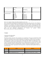
For instance, here's how a big firm like Fiat Group S.p.A. would fill the table (addresses don't refer
to the real cases):
Id
Name
Address
00001
Fiat Automobiles S.p.A.
Via Bianchi 18, Torino (TO) – ITALY
00002
Alfa Romeo Automobiles S.p.A.
Via Neri 19, Milano (MI) – ITALY
00003
Lancia Automobiles S.p.A.
Via Rossi 20, Torino (TO) – ITALY
32
Energywise Technology & UUDM&M Interfacing
00004
Fiat Light Commercial Vehicles S.p.A.
Via Verdi 21, Torino (TO) – ITALY
00005
Abarth & C. S.p.A.
Lerchenfelder Str. 13, Wien – AUSTRIA
Tab. – Hypothetical configuration of the table “Company”
The five companies listed in Tab.X are partially controlled by the huge firm Fiat Group S.p.A.:
they're big enough to be considered as independent companies, which enjoy a certain autonomy
(even if not complete). Speaking in Business Economics terms we could say that Fiat Group S.p.A.
adopts in general an Holding model; it manages directly one or more business areas of the
controlled companies, and applies internal horizontal strategies at the same time. The particularly
interested reader can delve into the argument by consulting “Economia e Gestione delle Imprese, 2a
Edizione, McGraw-Hill” [Fontana/Caroli, 2006] (in Italian).
Office
Connections with other tables:
OFFICE N:1 COMPANY
OFFICE 1:N IMAGEFLOOR
Each company owns one or more offices: what do we mean with this term?
An office is generally a medium/small enterprise which is completely controlled by a larger
organization (Company). Examples of offices are the small enterprises which have a complete
dependency on a bigger one, or the foreign small corporations of a Multinational Company.
To take our case of study, the Loccioni Group has got 2 offices:
•
•
A.E.A. & SUMMA S.r.L. (Via Fiume 16, Angeli di Rosora (AN) – ITALY);
General Impianti S.r.L. (Via Monteschiavo 3, Moie di Maiolati (AN) – ITALY).
Nevertheless, the Marketing section of the Group has recently decided to eliminate those original
names, preferring an explicative approach. Now the enterprise “A.E.A. & SUMMA S.r.L.” is named
“Loccioni Office of Angeli di Rosora”, while “General Impianti S.r.L.” in now named “Loccioni
Office of Moie”.
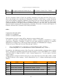
Taking again the example of the Fiat Group S.p.A., here's how the rows of the table “Office” would
be filled, relatively to the company “Lancia Automobiles S.p.A.” (without considering the foreign
offices):
Id
Name
Address
FkCompany
...
...
...
...
00056
Lancia Office of Torino
Via Torinesi 20, Torino (TO) – ITALY
00003
00057
Lancia Office of Roma
Via Romani 40, Roma – ITALY
00003
00058
Lancia Office of Padova
Via Padovani 41, Padova (PD) – ITALY
00003
00059
Lancia Office of Genova Via Genovesi 42, Genova (GE) – ITALY
00003
00060
Lancia Office of Palermo Via Palermitani 43, Palermo (PA) – ITALY
00003
33
00061
Lancia Office of Napoli
Via Napoletani 44, Napoli (NA) – ITALY
00003
...
...
...
...
Tab. - Hypothetical configuration of the table “Office”
Of course the office names and their associated addresses are purely invented.
Note that the FkCompany field, the foreign key which refers to the table Company, is filled with the
primary key of Lancia Automobiles S.p.A. (Id in Company = 00003).
Department
Connections with other tables:
DEPARTMENT 1:N SWITCHPORT
Well organized companies, and not only, can be defined as a set of departments working together
for the same target and goals whenever required. There could be several kind of grouping criteria in
a general office:
•
based on the input of the industrial processes, when several operative units are grouped
according to the technical/economic nature of the activities (like in an enterprise: Production,
Marketing, Financial Administration, Human Resources, etc.), or to subject (for example in a
hospital: General Medicine, Ophthalmology, Otolaryngology, etc.), or to the applied technology;
•
based on the output of the industrial processes, when several operative units are grouped
according to final product or to the product's end market, customer category, geographic area;
•
based on the industrial processes, when all the operative units are grouped together because
they are working on the same task or process;
•
…
It's up to economists to go into the details of this matter. The only thing we can say is that any
enterprise should be partitioned into departments even when it doesn't seem really necessary.
In the EnergyWise field it's very important to consider a situation like this; now we will explain
why. Let's take the company where we (the undersigned and Michel Uncini) have worked in, the
Loccioni Group, and more specifically the office of Moie. Here we can find essentially 5
departments:
•
Commercial: the commercial employees' task is to create and maintain commercial relations
with other enterprises, which operates either in the same and in different sectors, and with actual
and potential customers. Moreover they establish the prices of the products, and they also manage
the economic budget.
•
Project Managers: it consists of few elements, the persons which have high responsibilities
on the supervision of the projects. In the particular case of Loccioni Group it's constituted by all
those people with special qualifications and with responsibilities on following computer science,
mechanic and electrical projects, from the beginning to the end.
34
Energywise Technology & UUDM&M Interfacing
•
Technicians: all those people who work in the technical environment of the enterprise, like
electricians, systems engineers, computer hardware experts, etc. Generally this is the department
which count the highest value of workers, especially in the case of enterprises such as Loccioni
Group.
•
Design: includes all the engineers and designers who create industrial projects, mostly
software (dedicated software, enterprises' internal software, commercial software) and electronic
ones (electrical panels and systems).
•
R&D (Research and Development): the part of an enterprise (people, equipment, financial
resources) dedicated to the study of new technological innovations, for the improvement of old
products and old work processes, and most importantly for the creation of new technologies and
products. Very often, in order to achieve their goals, employees are allowed to utilize advanced
tools of development, very expensive safety certifications, specialized software for the computerassisted development, electrical projects and mechanical sub-systems.
Fig. - Loccioni logo
One of the reasons which have prompted the Loccioni Group to invest financial capitals for the
research on the EnergyWise technology is that, in general, the working hours of employees from
different departments are not the same. Therefore we can theoretically switch off certain telephones
when they are not utilized, if we know the working hours of the employees of that department,
gaining a good energy saving.
For a better comprehension, let's think about the real case of the Office of Moie (a.k.a. General
Impianti S.r.L.). Commercial employees start to work at 9:30 a.m., and they can go home after three
hours, at 12:30 p.m.; the R&D programmers, on the contrary, start at 8:30 a.m. and go home at 6:00
p.m., with a break starting at 12:30 till 2:00 p.m.
This is a perfect example for explaining how EnergyWise can help the enterprises to save money,
since by applying a good power policy it could be possible to save a lot of energy (electric power).
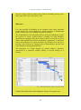
By using the presented UTM Application we could think of defining the following timetable for the
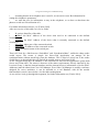
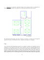
power management:
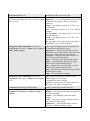
0:00 – 8:30 8:30 – 9:30 9:30 – 12:30 12:30 – 2:00 2:00 – 6:00
35
6:00 – 0:00
Commercial
OFF
OFF
ON
OFF
OFF
OFF
R&D
OFF
ON
ON
OFF
ON
OFF
Fig. - Timetable for the devices' power management in the Commercial and R&D departments, relative to G.I. S.r.L.
Obviously it is quite difficult to find such an ideal and optimal situation, since there will always be
someone who, for any reason, might not respect his working time. In any case it's possible to
overcome these drawbacks through advanced management policies (which can be defined both in
the Server-side and in the Client-side applications). The system can in fact be asked, for a certain
lapse of time (as much as desired), to switch on/off the devices in a different timetable respect to the
usual one. In the next chapters we will come back to this, specifying further details.
There's a last point to take into account: we said that the departments are somehow connected to the
offices. More in detail it's a so-called “N : N relation”, since an Office can have one or more
Departments, and a Department can be in common with more than one Office. So at this point an
obvious question arises: why didn't we consider this simple connection in the EW Database?
It's mostly a matter of convenience. Good database manuals teach us that a N:N relation should be
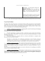
removed as soon as possible, because it's hard to deal with it. Let's mention how to do it briefly:
Fig. - Example of elimination of a N:N relation
In Fig.X is shown one of the well-known methods for the elimination of a N:N relation. As we can
see, the introduction of a third table is necessary; this table aims to contain all the existing relations.
This method is simple and effective, but also relatively expensive.
36
Energywise Technology & UUDM&M Interfacing
In our case we don't really need to keep track of which offices the departments belong to. The table
“Departments” is not even used in the Client-side Application; it is used in somewhere in the
Server-side one, but not so much. That's why we can afford not to consider the relation between
Departments and Offices, saving space in the EW Database.
ImageFloor & ImageArea
Connections with other tables:
IMAGEFLOOR N:1 OFFICE
IMAGEFLOOR 1:N IMAGEAREA
IMAGEAREA 1:N SWITCHPORT
The EnergyWise Server-side Application is designed for satisfying several needs. Among many of
them, one of the most important requirements is the usability; it shouldn't be necessary to consult
manuals or tutorials to discover all the powerful functionalities and the application's facets,
everything that is possible to do should be clear since the first approaches. Furthermore it should be
possible to monitor the situation of the enterprise's devices in the most “user-friendly” way possible,
even thought the Server-side Application is intended for people with a good knowledge in
Computer Science, like network administrators.
For those reasons the administrators (or whoever will use the application) should have the
opportunity of having a graphical and schematic vision of the offices, by using the planimetries of
those like a point of reference to keep track of the devices' position in a certain area.
In general, a planimetry is a plan representation (two dimensions) of a space or a surface, of a
terrain or a territory, of a building or a house, of a machine or an object. It concerns various
scientific and technical disciplines, and it is equivalent to the concept of “map” in technical
drawing for small representations (like in our case, where we just represent some maps of a
building).
If the administrator dispose of all the planimetries of the office (in a digital format), he can use them
to have a simplistic overview of the reality. If the reader would love to learn more about what we're
talking about, he can consult [Uncini 2010].
For the restricted purposes of this thesis, it would be enough to know that it's advisable (but not
really necessary) to give the application the possibility to store all the enterprises' planimetry
images. More specifically, the application should dispose of two distinct types of images:
•
ImageFloor: a planimetry relative to a floor (even of large dimensions) of the office, as
shown in Fig.X:
37
Fig. - Example of planimetry relative to an office's floor
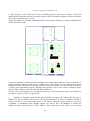
•
ImageArea: a planimetry relative to an area, preferably of small dimensions, of an
enterprise's floor. For a correct and optimal functioning of everything the best shape for the images
would be a rectangle with a good graphic definition, and the image should be very similar (or better
identical) to the real area which it refers to; a good example is the image in Fig.Y, which refers to
the dashed block in Fig.X:
38
Energywise Technology & UUDM&M Interfacing
Fig.Y – An ImageArea, referred to the ImageFloor
in Fig.X
At this point a question arises: « Why do we need to consider two types of images, one for the “big”
images and one for the “small” images? ».
It's a pure matter of usability. The idea is the same, but actually there are some differences between
them, especially of implementation. Some parts of the Server-side Application's code are simplified
and easier to understand, thanks to this distinction between “floors” and “areas”.
We will not go through the details of the code; again, for a more specific description of the problem,
see the Uncini's thesis [Uncini, 2010].
The utilization of those two tables implies some more benefits. Let's drop all the details about it,
which we will describe later on, and let's give a short explanation about the long-term idea.
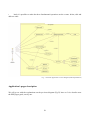
Once the Server-side Application is launched, it's possible to choose which Company and which
Office to refer to. At this point one of the floors of the selected Office will be shown as a default;
we can now deicide which floor we do want to visualize. Remember that the floor images are more
properly entities of the “ImageFloor” table.
Directly on the image of the floor some rectangular edges will be shown, which delimit the areas
where you can click on in order to get access to the corresponding ImageArea. The rectangular
edges are defined by four coordinates: TopLeftX and TopLeftY (the corner at the top in the left side
of the rectangle), BottomRightX and BottomRightY (the corner at the bottom in the right side of the
rectangle).
As we said, to each floor corresponds one or more ImageAreas. The fact that a single ImageArea
should be of small dimensions is important, mostly for these two factors:
•
a better supervision and comprehension of the administrator about the environment he wants
to monitor and manage;
•
a very reduced expense of machine instructions for the processors. Once the image is
loaded, the computer would also load all devices residing in that area; of course the less are the
devices, the less is the work to be done by the processor. The operation of loading is very complex
39
and expensive on itself, so it would be better to load the minimal number of objects, in order to
make the execution time be as much faster as possible.
Another advantage of using this approach is that, paying the needed attention, the “dead zones” do
not get defined. When we look closely to a planimetry of a floor we can realize that there are some
zones in where nobody will ever put a phone (ex. in the middle of a garage or of a space used for
the assembly of electrical panels) or any device at all. In this sense we can avoid the definition of
useless ImageAreas, focusing our attention only on the certain zones.
The major drawback of this approach is that to have the enterprise's planimetries in a digital format
is not enough, we also need to work with (simple) programs for graphic design to obtain the
ImageAreas. This point will be improved in a later version of the Application.
At this point the reader should be convinced that the usage of two tables for the images implies a
big comfort and usage, even if it could seem useless and without any sense.
Switch
Connections with other tables:
SWITCH 1:N SWITCHPORT
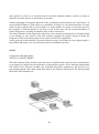
This table contains all the switches (network devices which forward selectively the received frames
to an output port) utilized for the application of EnergyWise policies. We're naturally talking about
PoE (Power Over Ethernet) switches, the technique that allows apparatuses and devices to be
powered through the same cable which links them to the Ethernet data network. We already talked
about PoE in the Document X.
Fig. - A switch (the rectangular box) connected to a number of devices
40
Energywise Technology & UUDM&M Interfacing
A switch is identified in a univocal way by its IP address, which is given statically; for this reason
the address is taken as primary key of the table. In order to query the switch we just need its IP, but
the “Name” field (which is not mandatory to specify) can be useful for those administrators with a
poor memory.
Keeping track of the switches is necessary for the network management; the Server-side
Application needs to know which switch is linked to the involved device (or group of devices) in
order to complete the operations it is supposed to perform.
For ease of use matters, it's necessary to associate the following three fields to each switch:
•
Enabled: boolean field which indicates if the switch at issue is enabled (1 = On) or not (0 =
Off). This field allows the system to avoid the blockage, for a long lapse of time, of the Server-side
Application when it asks for the power levels of a disabled switch;
•
Community: password needed for the authentication of the switch on the network, in order
to allow it to benefit from the network and EnergyWise services;
•
Port: indicates the switch port use for the SNMP interfacing. Generally this field takes the
number of the well-known UDP port as a value, the 161 port, since it is commonly used with the
SNMP protocol; this parameter could vary up to the administrator which is going to use the
application.
Note that here the name “port” is used in a software ambit; in this case a port can be thought as a
number between 1 and 65000, used to identify (together with a transport protocol and the IP
Address) a certain active socket.
SwitchPort
Connections with other tables:
SWITCHPORT N:1 SWITCH
SWITCHPORT N:1 DEPARTMENT
SWITCHPORT N:1 IMAGEAREA
In the hardware ambit, a port serves as an interface between the computer and other computers or
peripheral devices. Physically, a port is a specialized outlet on a piece of equipment to which a plug
or cable connects. So we are not talking about “software ports” like above, this time is about
“physic ports”.
It's easy to imagine that keeping track of the port on which a certain device is attached is very
important. Only knowing the name of the switch we can direct a “Shut Down” request on the right
domain, but we cannot operate on a specific object of that domain. If we also know the switch port
on which the concerned device is attached, instead, it becomes possible. For instance if a telephone,
and only one telephone, needs to be shut down (or switched on) in a certain instant, it's enough to
send a simple request to the application including the right “coordinates”.
A SwitchPort is unambiguously identified by two fields, IndexPort and FkSwitch.
IndexPort represents the number of one of the physic ports of the switch; for example in the Cisco
Catalyst 3560G series PoE-48 apparatus, which counts 48 ports, the field IndexPort can vary from
1006 to 1053. “48” is the number of Ethernet ports to which the devices can be connected; actually
41
the switch counts 6 more ports (indicated with numbers from 1000 to 1005), four for the connection
with other apparatuses, one for the power and the last one for the console.
FkSwitch is the foreign key derived from a switch. Since a switch inside a domain has got an
unambiguous IP Address, it's enough to indicate which port (between the available ones) we have to
indicate, so that we can obtain an univocal couple of values, as well as a multiple primary key.
FkDepartment and FkImageArea are respectively the foreign key of a department and of a
ImageArea. A SwitchPort can be associated, indeed:
•
to a department, so that it would be possible to execute a number of schedulings by
department on that port, and consequently on the port's associated device (entity);
•
to the image of an area, so that the SwitchPort could be easily traced inside the enterprise. In
the matter of this, that's the functionality of the parameters LocationX and LocationY: thanks to
them, it's possible to trace the exact coordinates of the point in which the SwitchPort is, in relation
with the ImageArea. For further information on this, see the “Maps” section in Chapter 6.
Lastly, the parameter NameInSwitch is the one given by default to the port, which represents a
mnemonic name: for instance the name of the physic port 1006 could be GigabitEthernet0/1, while
the port 1012 could obtain GigabitEthernet0/9 as a name, and so on. Those names can be easily
edited dynamically, to the administrator's liking.
Event
Connections with other tables:
EVENT 1:N SCHEDULINGTYPE
Events represent one of the principal reasons why the application was realized, either for Serverside and Client-side.
Substantially an event is something that should be executed in a certain date, in a certain time. In
particular with the term “something” we mean the editing of the power level on a device; therefore,
through events, it's possible to define the exact instant when we want a device (an IP telephone, or
a IP-based video surveillance camera) to change its own power level.
Events are connected with the SchedulingType table, which is needed for understanding what kind
of event we're going to deal with. Actually this is the only connection in the EW Database, but not
the unique at all: events are also connected with the Call Manager, whereby we can univocally
identify which device is referred, through the MAC Addresses.
Cisco CallManager is the software-based call-processing component of the Cisco IP telephony
solution. The software extends enterprise telephony features and functions to packet telephony
network devices such as IP phones, media processing devices, voice-over-IP (VoIP) gateways, and
multimedia applications. Additional data, voice, and video services such as unified messaging,
multimedia videoconferencing, collaborative contact centers, and interactive multimedia response
systems interact with the IP telephony solution through Cisco CallManager's open telephony
application programming interface (API). For further information about it, see the pages
42
Energywise Technology & UUDM&M Interfacing
http://www.cisco.com/en/US/products/sw/voicesw/ps556/ and
http://www.cisco.com/warp/public/cc/pd/nemnsw/callmn.
Two kinds of events exist, as follows.
•
Sporadic events: generally defined “una tantum”, once for all; in other words, an event is
sporadic if it defines an action that will not be executed in the following days, or at least not
systematically. For example, if a user wants to shut down (from the Client-side Application) his
own telephone for 4 hours because of a secondment nearby, he would choose to define this kind of
event with the right parameters.
•
Regular events: those events are cyclically repeated, day by day (except in festival days), so
in a regular way. These are the kind of events that most interest us, because they are the basis of the
enterprise's schedules; they are normally defined from the Server-side Application when the
administrator wants to define department-based schedulings, but it's also possible to define regular
events for employee-based schedulings.
An event is defined by the following fields. No one of them can be null at the moment of the event's
creation:
•
Id: univocal identifier of the event;
•
FkSchedulingType: indicates the scheduling type we're going to deal with. Further
information about the functionalities of this field will be discussed in the “SchedulingType” table's
description;
•
Value: value to consider. Depending on the scheduling (specified in FkSchedulingType) it
can assume different kinds of value: for instance if the scheduling is department-based Value will
assume department names, and if it is device-based it will assume the devices' MAC Addresses, and
so on;
•
TimeStart: timestamp of the moment in which the event should start;
•
TimeStop: timestamp of the moment in which the event should end;
•
EnergyLevel: power level (0 .. 10) that we want to give to the specified device during the
lapse of time between TimeStart and TimeStop;
•
Disabled: boolean value which indicates whether the event is enabled or disabled. This value
is at the beginning setted to 0 (that means enabled), because we assume that an even, as soon as it's
defined, is surely enabled and it can be executed once the determined time is come.
Once the TimeStop time is come, the event is disabled: Disabled=1. What happens next?
–
If the event is sporadic, Disabled won't come back to 0 anymore. It will reside in the Event
table until the time somebody will delete it; this to allow future searches on the past events, which
can be very useful to the administrators for many reasons.
–
If the event is regular, Disabled comes back to zero at midnight. This is to say that the event
is still active, and it will be executed again (every day, not festival days).
SchedulingType
43
Connections with other tables:
SCHEDULINGTYPE N:1 EVENT
The SchedulingType table is thought for a better organization of the events. As we said the events
can be sporadic or regular; we haven't explained what types of scheduling are sporadic and which
ones are regular, though.
In Fig.X we can see a strange representation of four scheduling types: Department, User, Device,
SwitchPort.
•
Department-based scheduling: it's possible to define global schedulings for entire
departments. These events are not definable through Client-side, but only through Server-side
Application: only administrators can deicide about multiple timeplans since it's a very important
operation. Of course this is the perfect example of regular events.
•
User-based scheduling: global schedulings for all the devices owned by a single user. If an
employee (in limited periods) uses to go to work one hour earlier than the normal start time for its
department, he can specify his needs even from the Client-side Application.
By using this kind of scheduling, all the devices associated to a determined user will observe the
event. For instance, if the user owns a telephone and an IP-based surveillance camera, he can define
a user-based scheduling to make both of them switch on at 8:00 a.m. and shut down at 5:30 p.m.,
even if the working hours of his department are from 9:00 a.m. to 6:00 p.m.. This type of
scheduling is sporadic, since we assume that a user can have particular needs just for limited
periods, at most one week long.
•
Device-based scheduling: schedulings for single devices, which can be found through their
MAC Address. The usage of this type is very common: a user can work in different offices of the
Company, so sometimes he is obliged to leave his normal workstation. In this case he can define a
device-based scheduling, where he says that he won't be in his usual office, and his telephone can
be shut down for a while. This type is sporadic, for the same reason as in the user-based
scheduling.
•
SwitchPort-based Scheduling: schedulings for single devices, which can be found through
the switch's port number. The only difference between this and the above scheduling is that it
doesn't matter what devices is connected, we're going to make power management operations on the
port.
44
Energywise Technology & UUDM&M Interfacing
Fig. - Four scheduling types, with associated priorities and granularity
Fig.X also suggests two important parameters: the Priority and the Granularity.
The lower is the level, the higher is the priority: if a SwitchPort-based event occurs at the same time
of a Department-based one, the first to be executed will be the SwitchPort-based event. It's good to
execute a small single operation before a huge and multiple one: a single user who wants a
particular event to be executed is supposed to have special needs, while a big team of employees
can wait for the normal execution.
The higher is the level, the most coarse-grained is the granularity: a department includes a set of
users, a user owes a set of devices. We can also say that a switch port works at a lower level than a
device: it's extremely easy to make some power management in a switch port, since launching
direct commands would be enough, but if we want the same for a device we have to search for it
first.
Further information about this matter in [Uncini 2010].
45
DeviceStatus
Connections with other tables:
none
This table represents the actual status of a device, univocally identified through its MAC Address.
With the term “status” we mean an integer number, which can assume values between 1 and 5, each
one with a specific meaning.
The “DeviceStatus” table is used for the integration between the “EnergyWise” and “IP Phone
Services” blocks, inside the UTM System. For a complete discussion of the matter, see [Uncini
2010].
The only important thing to know is that the corresponding values of “status” are the following:
1→
2→
3→
4→
5→
Available: the desired person is available;
Shut Down: the desired person is not available;
Busy: the desired person is temporarily busy, he hopefully will be available soon;
Meeting: the desired person is at a work meeting;
Don't Bother: the desired person does not want to be disturbed.
SynchronizeMacs
Connections with other tables:
none
Let's see the last table of this EW Database. SynchronizeMacs is a sort of a log table, very useful for
keeping track of the actions that has been manually made on the network cables.
In a company we usually find well defined and fixed workspaces and each workspace has usually
an associated telephone (sometimes even more, but it's a more rare situation). In a stable situation
the network administrator knows exactly the association between telephone and user, but also the
association between telephone and switch port. Now, what happen if this Phone/SwitchPort
association gets modified?
First of all, note that Cisco IP Phones in table X can show all the information related to their own
users, thanks to the Call Manager. Therefore, from a whatever workspace, by configuring just few
simple parameters the telephone will show for example name and surname of the user, and change
its number according to the new user.
Now let's assume that the user A has one week off. User B, which temporarily cannot use his own
phone (it is out of order), deicide to borrow user A's telephone; he unplugs the Ethernet cable
connected to user A's phone, he take the device and plugs his own Ethernet cable to user A's phone.
At this point the Server-side Application would receive a trap SNMP packet, adverting him that on a
certain SwitchPort a different telephone (user B's) has been plugged on the user A's one: so now we
have an anomaly, which can be solved in two ways:
46
Energywise Technology & UUDM&M Interfacing
•
assuming that the new telephone user is user B, we can retrieve user B's information for
setting the telephone's parameters;
•
we want the user A's information to stay in the telephone, so we have to shut down the
phone to avoid user B's utilization of it.
For further information about it, see [Uncini 2010].
After an overview of this table, let's see its fields:
•
Id: unique identifier of the table.
•
OldMac: the MAC Address of the device that used to be connected to the defined
SwitchPort.
•
NewMac: the MAC Address of the device that is currently connected to the defined
SwitchPort.
•
IndexPort: index port of the concerned switch.
•
SwitchPort: IP Address of the concerned switch.
•
Name: mnemonic name of the switch port.
There's no need for a link between “SwitchPort” and “SynchronizeMacs”, unlike the sharp reader
would expect. The reason is simple: the Server-side Application can manage all the
synchronizations without much help from the database. This is kind of weird, but if the reader
would like to go through this, he will find all the needed answers in [Uncini 2010].
As we said previously, the EW Database is not sufficient on itself for the application's goals (both
Server and Client-side). The reason is that one of the minor requirements, directly imposed by the
Loccioni Group, is that the internal numbers and the internal devices' information (even the MAC
Addresses) must be taken from Cisco Call Manager. Even if the Call Manager is actually a software
designed for server machines, it can be intended as a real Database with all the needed
functionalities (search, insert, delete) for the tables management.
As we said we won't go through this argument, for further information see [Uncini 2010].
47
Fig. – EnergyWise Database Structure
48
Energywise Technology & UUDM&M Interfacing
Furthermore in a primal version of the application we used another table, “RAWLOG”. More than
for data storage reasons, this table has been essential for carrying out some measurement about the
enterprise's energy consumption. We will see more information and details about, later on.
Chapter 5 - EW Client-side Application
Overview
Previously we said that the Unified Telephony Management product (UTM) is not only composed
by the application written in C# with WPF support. This one is just the EnergyWise Server-side of
the total application: it's designed to be used only by network administrators, who have complete
control of all the PoE devices, and have all the privileges to do everything they want in the office,
or even the company: they can set the power level of an employee's telephone, or send messages to
whoever they want, etc.
The application provides a Client-side as well: an employee can execute certain operations
regarding himself, so he can carry out a limited extent of EW operations. The Client-side is just
usable concomitantly with the Server-side, which holds special internal procedures (threads)
triggered by the client's requests. We will go through the details of it later on; at the moment it's
just necessary to know that is not possible to use the web (Client-side) application without
launching the execution of the Server-side one in advance.
The Client-side Application, mostly for usability reasons, has been thought to be developed on the
Loccioni's Intranet to be always reachable in a simple and fast way from the totality of the
Company's employees. The idea, at the beginning, was to add a functionality directly on the Intranet
homepage: by pressing a button the Client-side Application would open, and the user would have
been able to use all its function from there.
Unfortunately a problem occurred: the network administrator responsible for the Intranet
management was quite busy in the last period (mine and Michel's internship period started in
February and ended in May 2010), so he didn't have much time to add the feature. Anyway it will
be provided soon, we'll probably come back and work few more days in order to complete this part.
Why have we chosen to provide this application on the Intranet? A normal client software
application would be too onerous for the network administrator, that should install a software
package on each computer of the enterprise: it's needless to say that a lot of enterprises count
thousands of computers inside them! It's always a good thing to avoid software packages
installations (when possible).A web site on Internet from which we can do all the operations
wouldn't be a good idea neither: without an operational Internet service it would not be possible to
apply any ot the provided operations.
49
PHP & Web Server
Since the internal Intranet of Loccioni Group is totally built in PHP, the Client-side of the UTM
Application uses PHP as well as a programming language; in this way it becomes simple to
integrate the software solution presented here with the already-existing Intranet. For a general
overview about PHP concepts and functionalities see Document X.
We initially chose the remote web server IIS (Internet Information Services). This is a good product
from Microsoft, really simple to install and to configure on Windows machines. A first version of
our client application has been built with IIS web server support; later on, when we tried to make
the application be more portable, we realized that IIS is not optimal (in our case), so we started to
use Apache. Since web servers is not the main matter of this thesis, in the following few lines of this
paragraph we'll give just some concepts about it.
Microsoft's IIS and its competitor Apache, developed by a volunteers team from the ashes of a
previous project, are undoubtedly the two most common web servers on the net. The main
difference between them is the platform they are developed for: IIS is for Windows-based servers,
while Apache is for the great Unix family. A point in favour of Apache could be the effort (partially
successful) of porting the web server on not-native platforms, for example Windows systems:
obviously the best performances can be obtained on native platforms, but it's rumoured that Apache
has a very good behaviour on not-native ones.
The “battle” between these two web servers has always been opened; consequently, nowadays
there's also a strong dualism between the two operating systems which support the platforms,
Windows and Unix. And, like in all the dualisms, each one considers its own product to be the best.
50
Energywise Technology & UUDM&M Interfacing
Fig. - IIS vs Apache: a strong dualism between the two webservers is still taking place
First of all we should say that the hardware used for the tests is determinant for the benchmarks.
Obviously we are talking about machines with the same potentialities, but obviously if a system is
optimized for having better performances on a machine configured in a certain way (and with
certain installed hardware) there's no chance for the others.
Furthermore, talking about both Linux and NT systems, we should say something about the
software:
•
for Linux systems the kernel version does matter: every new version is an improvement of
the previous one, so it's mathematical that a newer version of the kernel would guarantee better
performances than an older version;
•
for NT systems we can say the same as above but concerning the Service Pack:
unfortunately not all the benchmarks report which SP version was used, but as we said before it's
obvious that a newer version implies better performances.
For
further
information
the
reader
can
consult
the
http://server.html.it/guide/lezione/2241/apache-iis-vs-apache-i-benchmark/,
interesting benchmark results taken from real machines' experiments.
excellent
website
which also reports
▼ Document III : PHP
What it is
PHP (recursive acronym for PHP: Hypertext Preprocessor) is a widely51
used open source general-purpose scripting language that is especially
suited for web development and can be embedded into HTML.
But what does that mean? An example:
<!DOCTYPE HTML PUBLIC "-//W3C//DTD HTML 4.01 Transitional//EN"
"http://www.w3.org/TR/html4/loose.dtd">
<html>
<head>
<title>Example</title>
</head>
<body>
<?php
echo "Hello World!";
?>
</body>
</html>
The code above will print Hello World! in a blank webpage.
Instead of lots of commands to output HTML (as seen in C or Perl), PHP
pages contain HTML with embedded code that does "something" (in this
case, prints output). The PHP code is enclosed in special start and end
processing instructions <?php and ?> that allow the programmer to jump
into and out of the "PHP mode."
What distinguishes PHP from something like client-side JavaScript is that
the code is executed on the server, generating HTML which is then sent to
the client. The client would receive the results of running that script, but
would not know what the underlying code was. It's even possible to
configure a web server to process all the HTML files with PHP, and then
there's really no way that users can tell what you have up your sleeve.
The best things in using PHP are that it is extremely simple for a
newcomer, but offers many advanced features for a professional
programmer.
Although PHP's development is focused on server-side scripting, users can
do much more with it.
What PHP can do
Anything. PHP is mainly focused on server-side scripting, so it's possible
to do anything any other CGI program can do, such as collect form data,
generate dynamic page content, or send and receive cookies. But PHP can
do much more.
There are three main areas where PHP scripts are used.
•
Server-side scripting. This is the most traditional and main target field
for PHP. Three things to make this work are needed. The PHP parser (CGI or
server module), a web server and a web browser. We need to run the web server,
52
Energywise Technology & UUDM&M Interfacing
with a connected PHP installation. We can access the PHP program output with
a web browser, viewing the PHP page through the server. All these can run on
an home machine if we are just experimenting with PHP programming.
•
Command line scripting. We can make a PHP script to run it without any
server or browser. We only need the PHP parser to use it this way. This type of
usage is ideal for scripts regularly executed using cron (on *nix or Linux) or
Task Scheduler (on Windows). These scripts can also be used for simple text
processing tasks.
•
Writing desktop applications. PHP is probably not the very best language
to create a desktop application with a graphical user interface, but if the user
knows PHP very well, and would like to use some advanced PHP features in a
client-side applications he can also use PHP-GTK to write such programs. We
also have the ability to write cross-platform applications this way. PHP-GTK is
an extension to PHP, not available in the main distribution. If the reader is
interested in PHP-GTK, he can visit http://gtk.php.net/.
PHP can be used on all major operating systems, including Linux, many
Unix variants (including HP-UX, Solaris and OpenBSD), Microsoft
Windows, Mac OS X, RISC OS, and probably others. PHP has also
support for most of the web servers today. This includes Apache,
Microsoft Internet Information Server, Personal Web Server, Netscape
and iPlanet servers, Oreilly Website Pro server, Caudium, Xitami,
OmniHTTPd, and many others. For the majority of the servers, PHP has
a module, for the others supporting the CGI standard, PHP can work as a
CGI processor.
So with PHP, we have the freedom of choosing an operating system and
a web server. Furthermore, we also have the choice of using procedural
programming or object oriented programming, or a mixture of them.
Although not every standard OOP feature is implemented in PHP 4,
many code libraries and large applications (including the PEAR library)
are written only using OOP code. PHP 5 fixes the OOP related
weaknesses of PHP 4, and introduces a complete object model.
One of the strongest and most significant features in PHP is its support
for a wide range of databases. Writing a database-enabled web page is
incredibly simple. The following databases are currently supported:
- Adabas D
- dBase
- Empress
- FilePro (read-only)
- Hyperwave
- IBM DB2
- Informix
- Ingres
- InterBase
- FrontBase
- mSQL
53
- Direct MS-SQL
- MySQL
- ODBC
- Oracle (OCI7 and OCI8)
- Ovrimos
- PostgreSQL
- SQLite
- Solid
- Sybase
- Velocis
- Unix dbm
We also have a database abstraction extension (named PDO) allowing us
to transparently use any database supported by that extension.
Additionally PHP supports ODBC, the Open Database Connection
standard, so any other database supporting this world standard can be
connected.
PHP also has support for talking to other services using protocols such as
LDAP, IMAP, SNMP, NNTP, POP3, HTTP, COM (on Windows) and
countless others. We can also open raw network sockets and interact
using any other protocol. PHP has support for the WDDX complex data
exchange between virtually all Web programming languages. Talking
about interconnection, PHP has support for instantiation of Java objects
and using them transparently as PHP objects. We can also use our
CORBA extension to access remote objects.
PHP has extremely useful text processing features, from the POSIX
Extended or Perl regular expressions to parsing XML documents. For
parsing and accessing XML documents, PHP 4 supports the SAX and
DOM standards, and we can also use the XSLT extension to transform
XML documents. PHP 5 standardizes all the XML extensions on the
solid base of libxml2 and extends the feature set adding SimpleXML and
XMLReader support.
At last but not least, we have many other interesting extensions, the
mnoGoSearch search engine functions, the IRC Gateway functions,
many compression utilities (gzip, bz2, zip), calendar conversion,
translation...
For further information please visit the PHP Project homepage,
http://php.net/index.php.
Application's Use-Cases
54
Energywise Technology & UUDM&M Interfacing
The Intranet application is constituted by 8 web pages, written in HTML/PHP code. Most of them
have a corresponding style sheet (CSS), for a clear and simple programming style. Each web page
has a well-known role, that we're going to describe in the following pages without going through
the code details.
In Fig.X we can see the use-case diagram relative to the Client-side Application. The use-cases are
essentially descriptions about “how to use” a system, i.e. how you can read it in a user manual.
The “Use-Case” concept has been proposed for the first time in 1987 by Ivar Jacobson, one of the
major UML authors. Nevertheless the diffusion of the term started from 1992 with the publication
of the book “Object-Oriented Software Engineering. A Use Case Driven Approach".
The technique of using the Use-Cases is an important help for the discovery and the clarification of
a system's requirements. Using the Use-Cases means:
•
to identify who (people or external systems) will have to use the system;
•
to understand what are the objectives we want to obtain by using the system (more or less
we need a use-case for each objective);
•
to study in deep each use mode, speaking in terms of concrete scenario descriptions,
clarifying how we start, the user's expected answer from the system, the sequence of steps of the
complete interaction, eventual external subjects which are still involved with the complete
mechanism.
Use-Cases greatly facilitates the requirements discovery, the customers' needs (and also of the other
parts of the system) understanding and their progressive clarifications. It also constitutes an optimal
starting point for the activities of analysis and design, implementation and system testing.
Use-Cases are also used in business process modelling and re-engineering contexts, other than in
the software developing sector.
The spreading of the Use-Cases has been immediate from the beginning. Jacobson's proposal was
accepted from the vast majority of the software developing experts, both as an efficient working
method for the requirements management, and as a starting point for the analysis and the design (in
particular concerning the object-oriented approach). Use-Cases became a fundamental UML
component, and a iterative processes element as well. For a complete Use-Cases and general
diagrams description the reader can consult the optimal book “Software Engineering 8th edition,
Addison Wesley / Pearson Education” [Sommerville, 2007].
Without any explanation the following diagram (Fig.X) would certainly be not that clear to the
reader, but later on he will have the possibility to comprehend all the application functionalities; all
the parts of which the application is composed will be described in details. Just informally:
•
in order to get access to all the application's functionalities, user must log in;
•
once the user is logged in, it's possible to visualize what and how many devices are currently
associated to him; from here it's also possible to set device's power levels and to check (both
graphically and textually) which events are associated to him;
•
it's possible to make use of three telephonic services, provided by the Server-side
application: call number, send message, send notification.
55
•
lastly it's possible to make the three fundamental operations on the events: delete, edit and
add new ones.
Fig. – Client-side Application Use-Case Diagram (UML Representation)
Application's pages description
We will go on with the explanations on the previous diagram (Fig.X) later on. Let's describe now
the PHP pages goals, one by one.
56
Energywise Technology & UUDM&M Interfacing
login.php
It's the login page, the first in chronological order to appear once the Client-side Application is
launched. As in all the login pages, user name and password are requested in order to get access to
the main page (the Home page).
The matter of the username inside Loccioni Group is really simple to manage. Each person of the
enterprise, immediately after his hiring (both real contracts and internships for students) gets an
internal univocal identifier. This number (generally made of three or four ciphers) is also used as a
unique telephonic number for rapidly tracing the colleagues.
This approach is obviously not used by all the enterprises in the world; however the Client-side
Application has been built thinking on this kind of structure.
All of this means that, as a username, it would be necessary to insert just a short series of ciphers;
this is an advantage for the user that should not remember tough predetermined names, or insert an
internal e-mail address as a username.
At the moment, the password is the same for all the employees in the enterprise; of course, in the
future each employee will have his own password, for obvious privacy and safety reasons (a system
where whoever can have access to everything is, of course, not a good idea).
A login, for its intrinsic nature, does not always succeed. In particular it's possible to identify four
cases in where the user cannot log in:
1.
Password missing → user has correctly written his own internal number, but he did not
insert his password;
2.
Wrong Password → user has correctly written his own internal number, but he inserted a
wrong password;
3.
Internal Number does not exists → user has inserted an internal number which does not
exists inside the enterprise's database, therefore it's not possible to retrieve information about any
device;
4.
Impossible to connect to the remote application → the Server-side Application is currently
not in execution, or some problems occurred during the connection attempts. A bug on the Serverside Application can be an explanation about this kind of error, which can be generated by a
malfunctioning of the network connection as well.
57
Fig. - login.php page
session.php
It's the page where we define the current session. First of all let's define what it is and how
important a session is inside a web application context.
Sessions are the simplest ways for user identifications, from the moment when they get a
connection to servers to when they interrupt the Internet connection (or, like in this case, the
Intranet one).
To be more clear let's imagine the following scenario: we want to provide a password to an user for
the navigation in a protected area, and then we want him to surf the net on this area. For each page
we should insert the password again, but we don't have to because the session is still active: that
means that the server we're working with “remembers” the password, and it knows that we have the
rights to do whatever we want.
The functioning of the session is very simple: the server machine opens a session with the
session_start() function, and assigns an univocal name to it . The session variables are stored into a
global array, named $_SESSION[], which is saved into a file with the same name as the session's
name. At the same time it stores a cookie inside the user's machine. Every time the server needs
some identification data it calls the cookie to go back to the session and to the saved file. In practice
we have a virtual memory on the server; every time we interrupt the connection the server deletes
everything (included the cookie).
The page “session.php” is not directly visible to the user; the control is putted into the hands of this
page for few instants, just the time to define the global variable that are essential for the correct
functioning of the application. Once everything is setted up the control is immediately given to the
page “home.php”. The session is essentially defined by a certain internal number and a certain
58
Energywise Technology & UUDM&M Interfacing
password; these elements together constitute the variables that have to be used for the entire
duration of the connection.
It's possible to check whether the two types of login errors (missing or wrong password) are
occurred or not, directly from this page. Moreover, if in a certain point of the execution the user
decides to close the session, he gets redirected to this page where the session (with all its variables)
gets destroyed. In this way the next user, which for hypothesis is a spiteful person, cannot get access
to the previous user's information by clicking on the “Back” button of the web browser; all the
information have been deleted, so in order to get access again it's necessary to carry out a new
login.
home.php
It's the application's main page, in where it's possible to get access directly after the correct
definition of a session. This page shows all the information relative to an user's devices; for instance
if a user owes three devices, three tables will be shown in where it's possible to visualize:
1.
the devices' MAC Addresses, obtained through some queries to the Call Manager (for
further information about the Call Manager see the websites
http://www.cisco.com/en/US/products/sw/voicesw/ps556/ and
http://www.cisco.com/warp/public/cc/pd/nemnsw/callmn);
2.
the device type (represented by an icon, which would be for example a phone if we want to
represent a telephony device), obtained taking into account the first ciphers of the MAC Address.
Different string initials mean different devices: the abbreviation “SEP” is owned by telephony
devices, and this is an important thing to consider for the application's purposes. The other
abbreviations can be associated to generic devices, but right now it's not so important to pinpoint
them;
3.
the power level of the devices (through the colour of specific buttons, each one relative to a
level). This is obtainable through the collaboration of the two sides of the application, the Clientside – this one – and the Server-side. The Client-side first sends a TCP packet which indicates the
number “n” of devices we want to know the level of, and then it sends “n” packets each one with a
certain MAC Address; now it will receive “n” packets, each one with the power level associated to
the device, as answers.
From this page is also possible:
1.
to go in the part relative to the scheduling of the devices, by pressing on the “Schedule”
button;
2.
to modify the power level of the devices, by pressing on the relative button. By pressing a
button we trigger an event which sends an UDP packet to the Server-side Application, which
provides the event management: the power level of that device will be modified;
3.
to go in the part relative to the Gantt graphs (more of this later on);
4.
to go in the part relative to the Services (described in the next paragraph).
59
Fig. - home.php page
services.php
From this page we can carry out some simple operations on the enterprise's telephones. These
services are provided by the Server-side Application, so if we want to make use of them we must
get the remote application's support.
In particular the provided services on the telephones are the following:
•
Call Number: instead of calling an employee by typing a number on the telephone, it's
possible to launch a call through a computer. Even if Cisco IP Phones provide on themselves an
address book service, it's always better to use computers for a better visualization. The “Call
Number” service allows users to call a person by typing a number on the keyboard of a computer;
from the Server-side Application it is also possible to call more than one employee at the same time,
and this service will be implemented in the near future in the Client-side Application as well.
•
Send Message: it's possible to send messages from a computer to a phone device. Messages
are sent through HTTP protocol, so the length of each message must be at most equal to the
available space in a HTTP packet.
•
Send Notification: it's also possible to send just ring notifications from a computer to a
phone device. Of course this is the less important functionality, but it still can be useful in an
enterprise ambient: it represents, for example, the fastest way to remind something to an employee
which is not very close to your workspace.
Further information about these services in [Uncini 2010].
Users can get access to this page by pressing the “Services” button in home.php. The page
services.php will be visualized on screen, showing a form with two entries: one for the telephone
number (employee's internal number) we want to communicate with, and one for the optional
60
Energywise Technology & UUDM&M Interfacing
message. First of all we need to insert the number and the eventual message and then to confirm our
choices. After that, three new options will appear on the right: “Call Number”, “Send Message” and
“Send Notification”. By clicking one of these options (simple buttons) we will immediately be able
to carry out our preferred operation.
Fig. X and Fig.X+1 show how the services are implemented in the Client-side Application.
Fig. - services.php: how the page is shown at first
61
Fig. - services.php: the page after the parameters confirmation
schedule.php
In this page all the events related to a device are shown: given a MAC Address all the scheduling
events which concern it are extrapolated. All of this is possible because of the table “Event” inside
the EW Database, which is structured in such a way that it could be possible to associate a device
(and MAC Address with it) to a number of events (from 0 to N). We can think about a generic event
as an action to do at a certain instant of time: the actions is, in practice, the choice of a new energy
level (at least for the current implementation), like to shut down a device (lev.=0) and to switch it on
(lev.>0).
From this web page it is also possible to delete, edit and add new events related to a MAC Address;
of course these actions modify the Database, which can be manipulated through the Server-side
Application as well. By choosing one of the mentioned option (“Delete Event”, “Edit Event” and
“Add New Event”) the user is redirected to the page “confirm.php” that we're going to describe in
the next paragraph.
62
Energywise Technology & UUDM&M Interfacing
Fig. - schedule.php page
confirm.php
In this page the user can edit or choose new parameters of certain already existing events, and
receives notifications about the success or the failure of a certain operation. More precisely:
1. if the user wanted to delete an event from the database he receives a confirmation of successful
cancellation, or an error message (related to the database);
2. if he wanted to add an event on the database he receive, on his screen, an input form in which he
can enter all the information related to the event, such as start date and time, stop date and time,
power level to set. Once the form is filled in and the button “Submit” gets pressed the event gets
processed and inserted into the database if there are no errors in somewhere; if there are, an error
message is displayed (like in the cancellation case);
3. if he wanted to modify an already existing event the procedure to follow is analogous to the one
for inserting. The difference lies in the fact that the old parameters are given as a default: for
instance in Start Time we will find the old date and the old time, in such a way that, if the user
would like to modify just a small portion of the event, the operation would be simpler, faster and
more user-friendly.
63
Fig. - confirm.php page
socket.php
This page is not directly visible to the user; it just indicates the operations to carry out in order to
send an UDP packet from the Client-side to the Server-side Application. This page can be called in
two separate cases:
when the user presses a button to modify the power level of a certain device from the page
“home.php”. Once the button is pressed a request is sent to the Server-side Application through the
Client-side code; depending on what button has been chosen the application will set the power level
of the desired device. Once the operation has been done the page home.php gets refreshed.
when the user wants to make one of the operations provided by the page “services.php”. The
operations are the following:
-
Call Number;
Send Message;
Send Notification.
Depending on which operation has been chosen, the Client-side will send different messages to the
Server-side. All the types of messages include the sender and receiver numbers, and a message if
needed. Once the operation has been done the page services.php gets refreshed.
gantt.php
64
Energywise Technology & UUDM&M Interfacing
This page constitutes an exception compared to all the other pages presented so far. This is not a
proper PHP page indeed: it's a graph built with JpGraph.
JpGraph is a Object-Oriented Graph creating library (for PHP >= 5.1). The library is completely
written in PHP and ready to be used in any PHP scripts (both CGI/APXS/CLI versions of PHP are
supported). The library can be used to create numerous types of graphs either on-line or written to a
file. JpGraph makes it easy to draw both "quick and dirty" graphs with a minimum of code as well
as complex graphs which requires a very fine grained control. The library assigns context sensitive
default values for most of the parameters which minimizes the learning curve.
For further information about JpGraph please visit http://www.aditus.nu/jpgraph/.
The presented library also offers Gantt graphs support (see Document XX). The page gantt.php
contains the needed code for two types of queries:
1.
what events are associated to the devices of a certain employee, with the limited extent of
today's date;
2.
what events are associated to the devices of a certain employee in the totality of the events
reported in the Database.
When the related button is pushed the graph gets visualized on screen. “How” this is done depends
on the web browser where we want the application to run on: for example by using Internet
Explorer (v7) the graph is visualized in a new window, while by using Mozilla Firefox (v3) a new
tab gets opened.
Anyway the graph will be displayed as in the example in Fig.X. On the left column all the
employee's devices are given, identified by MAC Address, while at the top there's a timeline which
is automatically managed by the library “jpgraph_gantt.php” (this is the PHP page to call when we
want to work with this kind of graphs). Inside the graph's body some bars are shown, as in Gantt's
philosophy; they can change colour depending on the level the devices are supposed to adopt in that
lapse of time. By analogy with the standard Cisco EnergyWise colours, and also for a better and
simpler comprehension:
–
–
–
–
–
–
Lv.10 and Lv.9:
Lv.8 and Lv.7:
Lv.6 and Lv.5:
Lv.4 and Lv.3:
Lv.2 and Lv.1:
Lv.0:
red bar;
yellow bar;
green bar;
blue bar;
brown bar;
black bar.
65
Fig. - gantt.php page
▼ Document IV : Gantt Graph
What it is
A Gantt diagram is a graphical chart that allows to model the tasks
planning for the realization of a project. It was invented in 1971 by
Henry L. Gantt.
Since it is relatively simple to read the Gantt diagrams because of their
structure, this instrument is used by almost the totality of the Project
Managers in all the sectors. The Gantt Diagram represents an instrument
for the PM that wants to graphically draw in a simple way the progress,
but it's also a good media between the sever actors involved in a project,
especially of big dimensions.
Creation of a Gantt diagram
In a Gantt diagram each task is represented by a line, while the columns
represent the calendar days, weeks or even months of working,
depending on the project duration. The estimated time for an action is
represented on a horizontal bar: the left end of this bar is positioned on
the scheduled start date, the right end on the scheduled completion date.
The tasks can be sequential (one by one) or executed in a parallel way.
When the tasks are sequential we can represent prior relations through an
arrow which starts from the action in point and goes to the final one. The
final task cannot be executed before the end of the action in point.
As an action progresses, the bar which represents it gets gradually filled,
proportionally to its progress level. In such a way it's possible to rapidly
have an overview of the project's progress by tracing a vertical line in
correspondence to the current date. Therefore the completed actions are
on the left side of this line, the not-yet-started ones are on the right, while
the actions currently in progress are crossed by the line. If something
66
Energywise Technology & UUDM&M Interfacing
does not comply with this model, there must be something wrong: in the
major part of the cases, the action is late!
Milestones
It is also possible to highlight in the planning some other important
events besides the action themselves, which constitute a fundamental
point for the project: we're talking about the milestones.
The establishment of the milestones allows the Project Managers to split
the projects in clearly defined phases, avoiding too long deadlines
(generally the managers talk about «tunnel effect» to describe a project
with a long deadline but without intermediate expirations). A milestone
can be the production of a good document, the definition of a date for a
meeting, or the delivery of a demo project (a demonstrative project with
some partially-working functionalities).
The milestones in a Gantt diagram are actions without a duration,
represented as a particular symbol, usually a reversed triangle or a
lozenge.
Fig. - Gantt Graph example. Names are given in Italian.
Further information about Gantt Diagrams in http://www.gantt.com/.
67
Use-Case Descriptions
At this point the Use-Case Diagram in Fig.XX should be clear. Anyway, to be more precise, we
should now report the Use-Cases descriptions one by one. Even if we're talking about a diagram
born exclusively for the first approaches on applications, the related description is really important
as general documentation. Whose readers who are not interested in the technical aspects can skip
this section.
Name: Login
Initiator: User
Goal: Log into the system.
1.
User writes his internal number
2.
User writes his password
3.
User confirms
Extensions:
3.
Internal number not given
a.
System shows an error message
b.
System allows user to try again
c.
Resume at 1
3.
Password not given
a.
System shows an error message
b.
System allows user to try again
c.
Resume at 1
3.
Internal number does not exist
a.
System shows an error message
b.
System allows user to try again
c.
Resume at 1
3.
Wrong password
a.
System shows an error message
b.
System allows user to try again
c.
Resume at 1
Name: Visualize Devices Status
Initiator: User
Goal: Visualize all the information about a user's devices, which can be IP Phones, IP Cameras, etc.
1.
System shows n tables, where n is the number of devices that the user owns. A table shows the MAC Address of the
relative deviceand its current power level (from 0 to 10).
Extensions:
1.
Failed retreiving information about one or more devices
a.
System shows the table without a specified power level
Name: Today's Gantt
Initiator: User
Goal: Show the Gantt diagram of a specified device regarding the current day.
1.
System opens a new window or a new tab (depending on the OS) showing today's events, using a Gantt diagram.
Extensions:
1.
No planned events for the current day
a.
System shows an error message
Name: Set Device Level
Initiator: User
Goal: Set the power level of a certain device.
68
Energywise Technology & UUDM&M Interfacing
1.
User clicks on one of the buttons (11 in total) which represent the power level.
2.
System shows the same page with the new power level at the chosen device
Extensions:
2.
Failed sending request: something wrong with the Server Application
a.
System shows the login page
b.
System shows an error message
Name: Visualize Scheduling
Initiator: User
Goal: Visualize the planned events for a certain device.
1.
System shows the overall planned events for the chosen device
Extensions:
1.
No planned events for the chosen device
a.
System informs User that there are no events planned, and suggest him to create one
Name: Overall Gantt
Initiator: User
Goal: Show the Gantt diagram of a specified device, speaking about the overall situation.
1.
System opens a new window or a new tab (depending on the OS) showing the overall events, using a Gantt diagram.
Extensions:
1.
No planned events for the device
a.
System shows an error message
1.
Too much events are planned: impossible to report the overall situation in a graphical way
a.
System shows an error message
Name: Make Operation
Initiator: User
Goal: Execute an operation on the events, regarding a certain device.
1.
User choose an operation on the events, which can be one between the following ones: Add, Edit or Delete
2.
System shows the relative page
Extensions:
none
Name: Add Event
Initiator: User
Goal: Add an event for a certain device.
1.
User clicks on the button for adding an event
2.
System shows a form which the user has to fill in
3.
User fills the form with Start Time, Stop Time, Power Level
4.
User confirms
Extensions:
4.
Start Time or Stop Time does not exists, or datetime overflow problem
a.
System shows an error message
4.
Start Time is equal or bigger than the Stop Time
a.
System shows an error message
4.
There's an already existing event which collides with the new one
a.
System shows an error message
Name: Edit Event
Initiator: User
Goal: Edit an already existing event for a certain device.
1.
User clicks on the button for editing an event
2.
System shows a form which the user has to fill in
3.
User fills the form with Start Time, Stop Time, Power Level
4.
User confirms
Extensions:
4.
Start Time or Stop Time does not exists, or datetime overflow problem
a.
System shows an error message
4.
Start Time is equal or bigger than the Stop Time
a.
System shows an error message
69
4.
4.
There's an already existing event which collides with the new one
a.
System shows an error message
Event not found: somebody has deleted the event
a.
System shows an error message
Name: Delete Event
Initiator: User
Goal: Delete an already existing event for a certain device.
1.
User clicks on the button for deleting an event
Extensions:
1.
Event not found: somebody has already deleted the event
a.
System shows an error message
Name: Use Service
Initiator: User
Goal: Use one of the services provided by the Server-side Application for the telephones.
1.
User clicks on the button for going into the Services section
2.
User types the telephone number of the receiver and the eventual message to send him
3.
User confirms his choices
4.
System shows a new section: now the user can choose the operation to do
5.
User clicks on one of the following buttons, depending on his intentions: Call Number, Send Message, Send Notification
Extensions:
none
Name: Call Number
Initiator: User
Goal: Make a call to an employee inside the enterprise.
1.
User clicks on the button for calling a number
Extensions:
none
Name: Send Message
Initiator: User
Goal: Send a message to an employee inside the enterprise.
1.
User clicks on the button for sending a message
Extensions:
none
Name: Send Notification
Initiator: User
Goal: Send a notification to an employee inside the enterprise.
1.
User clicks on the button for sending a notification
Extensions:
none
State-Chart Diagram
So far in this section we have seen the Use-Case diagrams and related discussions. They are
absolutely useful to describe the high-level behaviour of an application, but they don't discuss the
hidden mechanism of the system. They are made for describing all those things that a user can see;
we can see how the system reacts when the user does something, or when some external event
occurs, but most importantly we make sure that the system actually does something important and
70
Energywise Technology & UUDM&M Interfacing
useful. The problem with so many systems is that they may satisfy many or most of their stated
requirements, but are still not really useful because they do not give the users what they want or
need; they do not work the way that people want or expect them to work.
That's why we need a new diagram that explains exactly how the application internally works, the
way in which it is programmed.
The Statechart Diagrams allows to describe the dynamic behaviour of an object or a system. They
describe all the reachable states, and how the state of the concerned object changes in relation to the
occurrence of the events. Therefore a statechart diagram is made by states and transitions.
A State is a situation, during the life of the concerned object, in which it satisfies a condition, it
executes an activity, or it waits for a certain event.
A Transition is a relation which joins a start state and an end state (not necessarily separate). The
transitions that go back to the same state are called self-transitions.
A transition is labeled with three elements, all optional: Event [Condition] / Action.
•
Event (trigger): the occurrence of a stimulus that can trigger a transition between states;
•
Condition (guard): logic expression to evaluate. If from a state come out more transitions,
their conditions must be mutually exclusive;
•
Action: it is associated to the transition, it is considered a rapid process, not interruptible
from an event.
Again, for a detailed description of the statecharts we suggest the reader to consult the book
“Software Engineering 8th edition, Addison Wesley / Pearson Education” [Sommerville, 2007].
71
Fig. - State-Chart Diagram relative to the Client Application
The resolution of the statechart above could not be very high. For a better comprehension see the
attached folder, with all the images that have been used on this thesis.
Cap. 6 – EW Server-side Application
The other side of the Application
In the previous chapter we described the Client-side of the EW Application. It's not our intention to
present the other side as well: an extremely wide discussion of the Server-side Application is given
in [Uncini 2010].
Nevertheless the author of this thesis has partially collaborated to the realization of the Server-side
Application, so he feels the need to report what he worked on in the next pages.
72
Energywise Technology & UUDM&M Interfacing
We're talking about particular “blocks” that are integral part of the Server-side, but they can also be
seen separately; therefore it's possible to describe them one by one, in a very manageable way.
In particular we are going to analyse, in the order:
•
•
•
the part concerning the application graphs;
the part concerning the enterprise's mapping system;
the application that allows the power management of the enterprise's computers.
Graphs
In the Server-side Application's main window it's possible to visualize a constant presence that
continuously upgrades and shows new results. We're talking about an Area-chart that represents the
instantaneous power consumed, relative to the network of telephones during the phase of
monitoring.
In order to obtain the instantaneous power it's just necessary to send SNMP requests to the
concerned switches: the object of our interest has "1.3.6.1.4.1.9.9.683.1.6.1.8" as OID, and
“cewEntEnergyUsage” as name. The description of this object says:
"This object indicates the current usage for the Cisco EnergyWise entity. This should be less than or
equal to the power that can be consumed at that specified level."
For the definition of the graph we used a Visifire, a WPF component specialized in the multi-type
graphs building; among the available options, Visifire allows the construction of several graph types
such as pie, bars, area, etc.
It's also possible to customise the selected choice through particular colours and graduated
shadings, labels to suggest what the Cartesian axes mean, 3-D activation, etc.
Here's the high-level description of Visifire, available in the homepage of the web site
http://www.visifire.com/:
“ Visifire is a set of data visualization controls - powered by Microsoft® Silverlight™ & WPF.
Visifire is a multi-targeting control which can be used in both WPF & Silverlight applications.
Using the same API, charts in both Silverlight & WPF environments can be created within minutes.
Visifire Silverlight Controls can also be embedded in any webpage as a standalone Silverlight App.
Visifire is independent of server side technology. It can be used with ASP, ASP.Net, SharePoint,
PHP, JSP, ColdFusion, Python, Ruby or just simple HTML. ”
Through the graphs it' also possible to quantify the amount of saved energy inside the enterprise in
certain lapses of time, and that's not all. Here (Fig.X and X+1) is how the graph relative to the
instantaneous energy consumption is shown, in different moments (these graphs are taken from
[Uncini 2010]):
73
Fig. - Area chart screenshot, 2 IP Phones which consume 5 Watts each, running without any power management
Fig. - Area chart screenshot, 2 IP Phones which consume 5 Watts each, running during a power management made through the
Server-side Application
For demonstrative purposes we just used two Cisco phones (both model 7940).
In the first graph we can see that the two telephones together consume 10 Watts: in stable conditions
a Cisco 7940 consume 5 Watts, indeed. In the second graph we note that, after shutting down and
then switching on them, they do not consume 10 Watts anymore: they consume 14 Watts. This is a
peculiarity of all Cisco phones, which at first consume more than the necessary (in this case 7
Watts), but after a while they regain stability conditions.
Statistics
We previously mentioned something about the RAWLOG table in the EW Database, but we did not
explain its functionality. Well, we made use of this table to conduct a sort of “poll”, and to verify
how much energy can be saved using EnergyWise policies.
74
Energywise Technology & UUDM&M Interfacing
Thanks to the help of some colleagues in Loccioni Group we found a way to conduct the
experiment in a very comfortable and easy way, by organizing a simple workbench.
For this workbench we utilized the following components:
•
Calibrated electric power measurer;
•
Switch Cisco Catalyst 3560G (48 PoE ports);
•
IP Phones:
- Nr. 1 Cisco 7906;
- Nr. 2 Cisco 7911;
- Nr. 3 Cisco 7912;
- Nr. 28 Cisco 7940;
- Nr. 2 Cisco 7960;
- Nr. 1 Cisco 7970.
The measurer internally holds a minicomputer (more specifically a PLC, Programmable Logic
Controller) which is able to send the collected data to RAWLOG table, adding a row for each
measurement.
This has been done in two phases, as described below:
1.
WITHOUT ENERGYWISE USE: we measured the total energy consumption (which is the
sum of the consumptions of the switch and the 37 telephones) for a week, without EnergyWise
policies usage.
2.
WITH ENERGYWISE USE: we measured the total energy consumption (which is the sum
of the consumptions of the switch and the 37 telephones) of the subsequent week, this time applying
EnergyWise policies. More specifically we keep the telephones at full energy from 7:30 in the
morning to 08:00 in the afternoon, shutting them down for the rest of the time; the switch has been
setted up to have full energy during all the time, because it wouldn't be possible to define
EnergyWise policies on an switch “out of order”.
In Fig.X we can see the energy trend during the first and the second week of workbench: we have in
black an example of energy consumed during the first week (where the consumption is more or less
the same at any time in a day), and in red an example of energy consumed during the second week
(where, during the time mentioned above, there's an energy consumption completely assimilable to
the switch's activity).
75
Fig. - Energy trend during EnergyWise utilization
Thanks to a simple application, written in C#, we obtained the result in Fig.Y. The image shows the
total energy consumed in the first week (without EnergyWise usage) and the one consumed during
the second week (with EnergyWise usage) at the end of the workbench experiment:
Fig. - Workbench results (WITH / WITHOUT ENERGYWISE USE)
76
Energywise Technology & UUDM&M Interfacing
Fig.Y, which refers to the total energy consumption of the telephones (so the consumption of the
switch is not considered), shows that in a week we have an average energy consumption of:
•
•
51.09 kWh without EW usage;
20.00 kWh with EW usage.
So the energy savings is remarkable: we have more or less the 60% less of energy consumed.
Maps
Thanks to a simple system for the representation of the enterprises' internals, it's possible to
visualize the workspaces of the employees with a good resolution and precision.
The main database (EW Database) contains, in particular, two tables for the purpose:
•
ImageFloor: it contains the “general” images of the enterprise's floors. Of course, given a
certain enterprise, we can find more than one image inside the table. For example the Loccioni
Group has two floors to add to the table, just for “Sede di Moie” (the floor names are “Pianoterra”
and “Primo Piano”).
Fig. - ImageFloor relative to “Primo Piano” in Loccioni Group, Sede di Moie
77
•
ImageArea: it contains the “particular” images of the enterprise's floors. An ImageFloor is
divided into one or (usually) more ImageAreas, which represent particular floor portions.
Fig. - ImageArea relative to a specific workspace, which is part of the
floor “Primo Piano”
The distinction between these two types of image is necessary: we already went through this
argument in Chapter 4, EW Database section, “ImageFloor & ImageArea” paragraph.
Usage
As we previously said, through maps usage it's very simple to visualize (in a graphical way) the
workspaces of the employees and relative device positions. Once the concerned ImageArea has
been chosen, the image gets loaded on screen: successively some requests to the Database are made
in order to obtain the devices' positions, relative to the particular image. Some little spheres get
loaded in previously chosen positions: each of them represent a device (at the moment we will just
mention telephones), and are coloured in different ways depending on the actual power level of the
device: green if the level is 10 (full energy), red if the level is 0 (shut down), black if the application
78
Energywise Technology & UUDM&M Interfacing
is still trying to retrieve the power level (refreshing phase). Successive versions of the EW
Application will also provide the rest of the colours, when it would be possible to effectively choose
one of the 11 possible power levels.
Under each sphere we can find a label that relates to the owner's initials (i.e. the user Antonio Rossi
will be referred as A.R.).
Fig. - Spheres and labels on an ImageArea
To give an exhaustive description of the workspaces is not the labels' objective. The real objective is
to easily find an employee just giving a simple look at the scheme. If we would want to know
further information about the devices we just have to move the mouse over the location of a sphere:
a tooltip will immediately appear, showing more details such as the owner's complete name,
device's MAC Address, associated Switch and SwitchPorts.
Once we have an ImageArea at our disposal and once all the associated devices are loaded it's
possible to carry out a series of operations:
1.
Adding a workspace: given Switch and SwitchPort in input, the system asks the user to
indicate the exact position of the device (the position should be as more as possible faithful to
reality in order to avoid unpleasant issues in the future) using the mouse pointer. As soon as
everything is determined some SNMP requests are sent to the Call Manager to obtain the
employee's name and the device's MAC Address. This action can be also seen as a test of data
79
consistence, because if new data gets loaded in an unexpected way there's a problem in somewhere,
which has to be solved.
2.
Deleting a workspace: indicated a device, this one will be deleted from the map. Note that
inside the Call Manager nothing is actually deleted, in order to not endanger the stability and
consistency of data .
3.
Modify the power level of a device: by right-clicking on a device a context menu is shown,
through which it's possible to choose the new level (ex. option “Switch Off” to set the level to 0
shutting it down, option “Full Energy” to set the level to 10 switching it on).
Everything is done through SNMP packets that get sent into the network; they constitute the heart
of the application, which is also based on the EW Database and on the enterprise's Call Manager, as
said before.
Shut-Down Application
What Cisco EnergyWise can do is what we described so far. At least for the moment it's possible to
manage the power consumption of telephones, IP-based video surveillance cameras and not so
much more devices; moreover in many devices it's not possible to specify any power level different
to 0 (device shut down) and 10 (device at full energy).
The biggest power consumers in an enterprise (like computers, routers, switches, etc.) cannot be
supervised and managed on the energy consumption field yet. Cisco Systems is currently working
on the realization of standards-de-facto and new network protocols that will make all this possible,
one day.
It is kind of useless to say that the work done so far is not really sufficient to guarantee important
and very advantageous savings inside an enterprise. The simple operation of shutting down the
phones can be an help, but way more significant savings could be reached with the power
management of devices with a huge need for energy, such as the computers.
So we can just say: let's give Cisco some more time. But what can we do while we're holding on?
PsShutDown: Executable
PsShutDown is a command-line utility similar to the Shutdown utility from the Windows 2000
Resource Kit, but with the ability to do much more. It is part of a growing kit of Sysinternals
command-line tools that aid in the administration of local and remote systems named PsTools.
PsShutDown requires no manual installation of client software: in order to install the component,
just copy PsShutDown onto your executable path, and type psshutdown with command-line options
defined below.
This executable program, freely downloadable from Internet at http://technet.microsoft.com/enus/sysinternals/bb897541.aspx, allows users to make the following operations on Windows
computers:
•
Suspension;
80
Energywise Technology & UUDM&M Interfacing
•
•
•
•
•
•
Hibernation (requires Windows 2000 or higher);
Poweroff;
Lock (requires Windows 2000 or higher);
Logoff;
Reboot;
Shutdown without poweroff.
Moreover it's possible to specify the collection of computers on which to perform the shutdown, the
operations time-out and much more. Of course there are some requirements to observe in order to
take advantage of these services on remote computers:
1.
the user who launches the application should know the IP address or the PC's name on which
to make the desired operations;
2.
the computers should be connected through a network in some way;
3.
the user who wants to make these operations should have the permissions to do it.
Regarding the point 3: if the application's user does not have administrator permissions, or in
general not enough permissions, he will not be able to do anything on remote PCs but only on the
user's one.
PsShutDown: List of Commands
The following is the list of PsShutDown (v2.52) commands. The reader can also find it by writing
“psshutdown.exe” from the Windows console.
81
Fig. - PsShutDown.exe commands
Syntax
82
Energywise Technology & UUDM&M Interfacing
psshutdown -s|-r|-h|-d|-k|-a|-l|-o [-f] [-c] [-t [nn|h:m]] [-v nn] [-e [u|p]:xx:yy] [-m "message"] [-u
Username [-p password]] [-n s] [\\computer[,computer[,...]|@file]
Options
-a
Abort a shutdown (only possible while countdown is in progress)
-c
Allow the shutdown to be aborted by the interactive user
-d
Suspend the computer
-e
Shutdown reason code (available on Windows XP and higher)
Specify 'u' for unplanned and 'p' for planned
shutdown reason codes:
xx is the major reason code (must be less than 256)
yy is the minor reason code (must be less than 65536)
-f
Forces running applications to close
-h
Hibernate the computer
-k
Poweroff the computer (reboot if poweroff is not supported)
-l
Lock the computer
-m
Message to display to logged on users
-n
Specifies timeout in seconds connecting to remote computers
-o
Logoff the console user
-p
Specifies optional password for user name. If you omit this you will be prompted to
enter a hidden password.
-r
Reboot after shutdown
-s
Shutdown without poweroff
-t
Specifies countdown in seconds until shutdown (default is 20) or the time of shutdown
(in 24 hour notation)
-u
Specifies optional user name for login to remote computer
-v
Display message for the specified number of seconds before the shutdown. If you omit
this parameter the shutdown notification dialog displays and specifying a value of 0
omits the dialog.
computer Shutdown the computer or computers specified
@file
Shutdown the computers listed in the file specified
PsShutDown: Usage
83
So far we presented what it's possible to do by using the PsShutDown Application, but we haven't
said anything about how all of this can be useful for our purposes. What we want is not a tool only
manageable through command line. A command-line tool, even if very easy to use, remains really
uncomfortable for the most of the people (specially if there are several computers to manage: to
write every time all the PCs where to operate would be just for crazy people).
Fortunately something comes to help us: it's C#, the same language used for the rest of the Serverside Application. With some C# lines of code we can call an executable program, such as
PsShutDown, and make it work giving to it the parameters it needs in a very comfortable way.
In particular we would like an application (or better, as we said, a “block” inside the Server-side
Application) very easy to manage that would make us pick up the computers we want and would
make us choose all the parameters we prefer; furthermore we want it to be manageable with a
graphic interface which has to be as much user-friendly as possible.
So, here's what has been developed. In the Server-side Application's main window there's a button
named “Shut Down Computers” in somewhere: when pressed, this button opens a new window like
the one presented in Fig.X:
Fig. - ShutDown Application's login page
Once a network domain is inserted in the apposite textbox and the “Enter” button is pressed, a new
window like the following (Fig.XX) will be opened:
84
Energywise Technology & UUDM&M Interfacing
Fig. - ShutDown Application's operations page
How it's simple to imagine, from this window it's possible to choose a number of options: we can
choose the type of operation to do (the radio buttons collection at the top), the time to wait before
the execution of the chosen operations (selectable from the combobox with the “Countdown” label),
the message to show on screen before the shutdown (it can be omitted), the network domain name
(initially this name coincides with the name given in input at the beginning) and user credentials
(who must have particular permissions to execute such important operations).
85
Furthermore it's possible to proceed in two ways: we can execute the shutdown of some of the
elements inside the listbox (which coincide with the computers currently connected in the network),
or we can execute it regarding a specific element.
In the first case it's necessary to select the concerned elements, putting a check on them, and to click
on the “Shutdown Selected Elements” button. In the second case we should manually fill the
textbox “IP or PC-name” with the IP Address or the name of the concerned computer, and then to
click on the “Shutdown Specific Element” button.
Once the command has been launched the affected computers will receive an alert message similar
to the one in Fig.X:
Fig. - Example of PsShutDown message
The message does not get visualized if the sender decides to execute the operation immediately
(Countdown = 0 seconds): in that case the user will not be warned in advance, and he will not have
any time for saving its own work or to make the necessary operations before the shutdown. This is
strongly not recommended specially if there are some delicate operations in progress, such as the
data backup.
If allowed to (Countdown at least >= 1 seconds), the user can abort the shutdown operation either
by pressing the “Cancel” button (if provided) or by typing from Windows command-line
“psshutdown -a” (of course this is going to work just for computers with PsShutDown program
installed).
86
Energywise Technology & UUDM&M Interfacing
Acknoledgements
Priceless is the help I received to give birth to this thesis. I say thank you to the following persons,
without which the writing of this thesis would not have been possible.
Michel Uncini ([email protected]): since ever my companion of adventures, I would say
that he has a good head on his shoulders. Really keen on Computer Sciences themes, fellow worker
on the EnergyWise project. Undoubtedly the most important and precious help on this thesis'
thematics.
Mirco Angeletti ([email protected]): Loccioni Group's Marketing and R&D Manager, the
first person starting to believe in the EnergyWise project and, even more important, in the abilities
of two young and wretched internship students. An inexhaustible source of motivation, desire to
discover, and disposability.
Michele Casci ([email protected]): supreme networks expert, loved and respected by
everyone inside the company. It's all thanks to him if we got introduced in the EnergyWise topic,
specially at the beginning of our adventure.
All the Loccioni Staff of Sede di Moie, R&D Department: although not directly involved in the
project, everybody were always available to answer to questions and curiosities, and to find the
solution to many kinds of issues. Even their help has been essential.
Chiara Belardinelli: my cousin, just become mother of a beautiful baby. She gave me an help to
correct the mistakes I made in the English version of this thesis.
My mother, my father, my grandma: they do not understand anything about EnergyWise, but they
allowed me to study; especially they always guided me to the right decisions and choices.
Considering these as the most important merits, I dedicate this thesis to them.
Many thanks to everyone.
References
MSDN Library (.NET Framework 3.5 WPF page)
http://msdn.microsoft.com/en-us/library/ms754130.aspx
Wikipedia (WPF page)
http://en.wikipedia.org/wiki/Windows_Presentation_Foundation
Cisco EnergyWise Technology
http://www.cisco.com/en/US/products/ps10195/index.html
Controlling Corporate Energy Consumption via the Enterprise Network, Nicholas Lippis
87
http://www.cisco.com/en/US/prod/collateral/switches/ps5718/ps10195/lippis_energywise_external_
final.pdf
Cisco EnergyWise Demo Presentation
http://www.cisco.com/assets/cdc_content_elements/flash/netsys/energywise/demo.html
Cisco EW At-A-Glance
http://www.cisco.com/en/US/prod/collateral/switches/ps5718/ps10195/at-a-glance_c45-514506.pdf
Cisco Networked Sustainability Framework
http://www.cisco.com/en/US/prod/collateral/switches/ps5718/ps10195/qa_c67-508150.html
Cisco EnergyWise Configuration Guide
http://www.ciscosystems.com/en/US/docs/switches/lan/energywise/phase2/ios/configuration/guide/
ew_v2.pdf
Cisco EW Technical Overview
http://www.aironet.info/en/US/prod/collateral/switches/ps5718/ps10195/prod_presentation_c97512619.pdf
Power Over Ethernet, alimentation goes on the Ethernet Cable
http://searchnetworking.techtarget.it/articoli/0,1254,19_ART_79745,00.html
Hyper-Terminal introduction
http://www.avitresearch.co.uk/USBTTL/hyperterminal.htm
Cisco CallManager
http://www.cisco.com/warp/public/cc/pd/nemnsw/callmn
Visifire web page
http://www.visifire.com/
Cisco SNMP Object Navigator
http://tools.cisco.com/Support/SNMP/do/BrowseOID.do?local=en
AllWebFree page
http://www.allwebfree.it/php_sessioni.php
IIS vs Apache Benchmarks
http://server.html.it/guide/lezione/2241/apache-iis-vs-apache-i-benchmark/
Use-Case Modeling
http://books.google.it/books?id=zvxfXvEcQjUC&printsec=frontcover&dq=usecase&hl=it&ei=Qs7qS93tBMua_QbJpNzeCg&sa=X&oi=book_result&ct=result&resnum=1&ved=
0CD8Q6AEwAA#v=onepage&q&f=false
PHP Introduction
http://php.net/manual/en/introduction.php
JpGraph WebSite
http://www.aditus.nu/jpgraph/
Psshutdown web page
http://technet.microsoft.com/en-us/sysinternals/bb897541.aspx
Gantt Diagrams – kioskea.net
http://it.kioskea.net/contents/projet/gantt.php3
Gantt Diagrams – Wikipedia
http://en.wikipedia.org/wiki/Gantt_chart
88