1
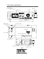
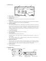
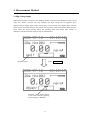
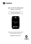
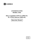
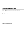
Piezobalance Dust Monitor
MODEL 3521
Operation Manual
PIEZOBALANCE DUST
MONITOR MODEL 3521
Read this manual carefully and understand the warnings
before operating the instrument.
Keep this manual handy for future reference.
03002
11 .10
Important Safety Information
Types and definitions of warning signs used in this operation manual are shown below.
Danger: To prevent serious injury or death.
Items under this heading show measures to prevent serious injury or death,
which may result if the instructions in this manual are not observed and the
instrument is operated inappropriately.
Caution: To prevent damage to the product.
Items under this heading show measures to prevent damage to the product
and conditions that affect the product warranty.
[Description of Symbols]
This symbol indicates a condition (including danger) that requires caution.
The subject of each caution is illustrated inside the triangle (e.g., the high
temperature caution symbol shown on the left).
This symbol indicates a prohibition. Do not take the prohibited action shown
inside or near this symbol (e.g., the do not disassemble symbol is shown on the
left).
This symbol indicates a mandatory action. A specific action is given near the
symbol.
Danger
* Never expose the instrument to flammable gas.
Do not use near
flammable gas.
* Never disassemble, heat, or discard the
battery pack in fire.
…… The battery pack may explode.
Explosive
Handle Properly
* Never perform the cleaning procedure
with the instrument set to high voltage
(if the high-voltage is active, the pointer
Prohibition
will be located at the center of the
indicator.)
…… Performing cleaning while the high-voltage is active may cause an electrical shock.
Caution
* Do not drop or strike the instrument.
…… Dropping or hitting the instrument may
cause damage or a malfunction.
Prohibition
* Never disassemble, modify or repair the instrument.
…… Failure to observe the above may cause a short circuit
or a malfunction.
Do not modify / disassemble
* Do not block the impactor inlet.
…… Failure to observe the above may cause a pump failure.
Prohibition
* Do not perform a measurement in an environment with extreme
temperature or humidity changes.
…… Using the instrument in an environment with extreme temperature or
humidity changes may cause an error in the measurement value.
Handle Properly
The allowable rate of change during a 2 minute measurement is:
Temperature: ± 1°C (0°C to 40°C), Humidity: ± 1%RH (30%RH to 80%RH).
* Do not wipe the instrument with a volatile solvent.
…… The body may deform or deteriorate. Use soft dry cloth to remove stains.
If stains persist, dampen the cloth in a neutral detergent and wipe
the instrument.
Do not use volatile solvents such as thinner or benzine.
Prohibition
* Make sure there is no turbulent air flow near the sampling inlet.
…… Turbulent air flow may cause a measurement error.
Handle Properly
* Do not clean the instrument in an environment where the
temperature is below 0 °C.
…… The cleaning sponge may freeze and cause damage to the sensor.
Prohibition
Table of Contents
1. Part Names and Functions ......................................................................................1
1.1 Part Names....................................................................................................................... 1
1.2 LCD Screen ..................................................................................................................... 2
1.3 Operation Keys ................................................................................................................ 2
2. Battery Indicator......................................................................................................3
3. Battery Charge .........................................................................................................4
3.1 AC/DC Adapter................................................................................................................ 4
3.2 Battery Charging Display ................................................................................................ 4
4. Parts Installation and Measurement Preparation ................................................5
4.1 Removal and Installation of the Rechargeable Battery Pack........................................... 5
4.2 Accessing and Storing the Cleaning Device .................................................................... 6
4.3 Confirming the Sensor Condition.................................................................................... 7
4.4 Cleaning the Sponge........................................................................................................ 8
4.5 Cleaning the Sensor ......................................................................................................... 9
4.6 Adjusting the Impactor Position .................................................................................... 10
4.7 Sampling Time............................................................................................................... 10
5. Measurement Method............................................................................................ 11
5.1 High Voltage Supply.......................................................................................................11
5.2 Measurement Start ........................................................................................................ 12
5.3 Measurement End .......................................................................................................... 13
6. Settings Menu .........................................................................................................14
6.1 Main Menu .................................................................................................................... 14
6.2 Sampling Time Menu .................................................................................................... 14
6.3 Data Output Menu ......................................................................................................... 15
6.4 Time Adjustment Menu ................................................................................................. 15
6.5 Communications Menu.................................................................................................. 16
6.6 Data Clear Menu............................................................................................................ 17
7. Printing ...................................................................................................................18
7.1 Connecting the Printer ................................................................................................... 18
7.2 Print Output Menu ......................................................................................................... 18
8. Regular Maintenance and Impactor Nozzle Replacement.................................19
8.1 Impactor Cleaning ......................................................................................................... 19
8.2 Removing and Cleaning the Needle .............................................................................. 20
8.3 Installing the Needle ...................................................................................................... 20
8.3 Installing the Needle ...................................................................................................... 21
8.4 Replacing the Impactor Nozzle ..................................................................................... 21
9. Main Specifications................................................................................................22
10. Troubleshooting....................................................................................................23
11. Warranty and After-sales Service .......................................................................24
12. Contact Information ............................................................................................26
1. Part Names and Functions
1.1 Part Names
Impactor
(unit: mm (inches))
Needle
65 mm (2.6”)
Display screen
PIEZOBALANCE DUST
MONITOR MODEL3521
180 mm (7.1”)
Display screen
contrast adjustment
Operation keys
Cleaning port
Power switch
Rechargeable battery pack
AC adapter socket
Cleaning
device
Battery pack release
Sponges
1
Cleaning device lock
150 mm (5.9”)
Communication port
1.2 LCD Screen
c
b
a
d
a. Date & Time:
g
f
e
h
Indicates current date & time.
b. Sampling Time:
Sampling time can be quick set to either 24s, 120s or custom set from 1-60 min.
c. Data Record:
Indicates the current number of data records (Max.500). When a measurement is complete,
“STORE” will flash here. To save the data, press [MEMORY].
d. Measurable Range:
The remaining measurable range is indicated by a bar indicator, which moves from left to
right as the sensor absorbs dust and the range decreases. When the sampled dust exceeds
approx. 10 µg (>Fundamental Frequency + 2000 Hz), “CLEANING” will flash here. The
cleaning procedure must be performed when the remaining measurable range is too small or
if “CLEANING” flashes.
e. Concentration Reading:
The concentration reading flashes during a measuring.
f. Operating Status:
“WAIT” flashes during cleaning and power-up.
“READY” flashes when high voltage is supplied and the instrument is ready for a
measurement.
The remaining sampling time is displayed during a measurement. The indicator bar
increases from left to right as time elapses.
g. High Voltage Indicator:
The high voltage status indicator displays when high voltage is being supplied. When the
pointer moves to the center of the frame (under the black block), the operating status
changes to “READY”, and the instrument is ready to perform a measurement.
h. Battery Indicator:
Indicates remaining battery power.
1.3 Operation Keys
Up key
Menu key
Start key
MENU
MEAS
CLN
SET
Set key
Down key
2
MEMORY
Supply or cut high
voltage power key
START
Data storage key
2. Battery Indicator
Remaining battery life is displayed when the instrument is powered on.
The battery indicator changes as shown below:
Full
¾
¾
Half
Requires
Battery indicator
recharge
flashes
Automatic
power off
The battery indicator flashes when the battery voltage drops below 9.3V. The AC/DC adapter
must be connected immediately to continue measuring.
If the adapter is not connected, the instrument will power off automatically.
3
3. Battery Charge
3.1 AC/DC Adapter
For prolonged measurements, the instrument should be powered using the supplied AC/DC
adapter (when AC100-240V power is available). Insert the adapter jack into the adapter socket on
the instrument first, and then to a power outlet.
Adapter jack
Adapter
socket
Adapter
When AC power is supplied, the battery charging status bar will display on the screen.
While the battery is being charged, the bar indicator will move.
When it is fully charged, the bar indicator will stop moving.
3.2 Battery Charging Display
The battery can be recharged while the instrument is
turned ON or OFF. The bar indicator shown on the right
indicates the battery is charging.
When the battery is fully charged, as shown on the right,
unplug the adapter.
In
charge
Charge
over
1) Caution: The input of the AC/DC adapter is AC 100-240V and the output is DC 12.5V. Do
not use an adapter other than the one supplied with the instrument. Using the wrong adapter
may cause a charging failure or damage the instrument.
2) The estimated continuous operating time using the rechargeable Ni-MH battery is approx. 4.5
hours. Charging time is approx. 5-8 hours.
3) If the instrument is not going to be used for an extended period, the battery should be charged
once a month in order to extend the service life of the battery.
4) The instrument can be operated using the AC adapter or battery power. If the adapter is
connected to the instrument a measurement can be performed simply by turning on the power.
If the instrument is going to be operated under battery power it is recommended that the
battery be fully charged before starting a measurement.
5) Turn off the instrument when it is not in use. Unplug the adapter when the device is not in use
and the batteries are not charging.
4
4. Parts Installation and Measurement Preparation
4.1 Removal and Installation of the Rechargeable Battery Pack
1) Press the rechargeable battery pack release, and slide the battery pack along the guiding
groove away from the release as shown below.
Battery pack release
Rechargeable battery pack
Guiding groove
2) Align the tabs on the rechargeable battery pack with the slots in the guiding groove and lift the
battery pack free from the instrument.
3) To reinstall the battery pack, reverse the above procedure.
5
4.2 Accessing and Storing the Cleaning Device
1) To access the cleaning device, hold the cleaning device while sliding the lock away from the
cleaning device as shown below.
Cleaning device
Cleaning device
lock
Rechargeable battery pack
2) After the lock is released, remove the cleaning device by lifting the front end.
Front end of
the cleaning device
3) To return the cleaning device to storage, place the rear end of the cleaning device onto the
battery pack first, and then push the front end of the cleaning device into the locker. After the
cleaning device is in place, push the lock to its original position to secure it.
3
2
1
4
6
4.3 Confirming the Sensor Condition
When the instrument is powered on, the screen below will display a flashing “WAIT” message in
the operating status field. After approx. 10 seconds the sensor will stabilize and the “WAIT”
message will stop flashing.
The measurable range of the sensor can be confirmed by the bar indicator and the frequency
displayed on the screen.
1) Confirming the Measurable Range using the Bar Indicator:
The bar indicator will be at full length immediately after cleaning. The bar will move to the
right, decreasing in length as dust accumulates on the sensor. When the remaining length of
the bar indicator is short, or when “CLEANING” is flashing, the sensor should be cleaned
immediately. (Refer to section 4.4 and 4.5 for cleaning.)
2) Confirming the Measurable Range using the Frequency display:
The frequency can be displayed by pressing △ or ▽ , and hidden by pressing
△ or ▽ again.
The frequency will increase as dust accumulates on the sensor. When the frequency exceeds
the Fundamental Frequency + 2000Hz, “CLEANING” will flash. Cleaning should be done
immediately.
* The frequency increases as the length of the measurable range bar indicator decreases.
Measurable range
Bar indicator
Frequency:
Display/Hide with
△ or ▽
Operating status
Caution:
Confirm that the bar indicator has sufficient length before starting a measurement. Never leave
dust accumulated on the sensor as it may prevent the bar indicator from recovering even after
cleaning. It can also affect the frequency display, which will affect the measurement accuracy.
7
4.4 Cleaning the Sponge
Preparation Before Cleaning
1) The sponge on the cleaning device must be moistened
before use. If the sponge is dirty or stained, put the cleaning
device into a vessel filled with clean water and a few drops
of neutral detergent, and let it soak for a few minutes (this is
not necessary for a new product).
2) When the stain is removed, rinse the sponge under running
water making sure to completely remove all the detergent.
3) Use a folded tissue or paper towel to remove all excess
water from the sponge. Repeat this process several times to
ensure the removal of all moisture.
4) Put 1-2 drops of the provided detergent (blue) on the
SMALLER sponge.
5) Put 2-3 drops of purified water on the LARGER sponge.
Caution:
1) Note that the two sponges differ in size. 1-2 drops of
detergent go on the smaller sponge. Only purified water
goes on the larger sponge.
2) If the sponge is dirty or stained with oil that cannot be
removed by washing it in clean water, put the cleaning
device into a vessel filled with clean water and 3-4 drops of
neutral detergent. After the stain is removed, rinse the
sponge under running water.
3) If the stain cannot be removed from the sponge or if the
sponge is damaged, it must be discarded. Please contact
your local distributor or our service center to purchase a
new sponge.
4) Any water droplets remaining on the cleaning device other
than the sponge itself must be removed completely using a
folded tissue or paper towel. If water drops are left on the
cleaning device when it is inserted into the instrument, the
drops may attach to the sensor or needle, causing a recovery
failure of the measurable range or failure when applying
high voltage.
5) Using an excessively moist sponge could lead to a
prolonged drying time. In addition, the instrument reading
may become unstable, and the “WAIT” message may not be
displayed.
6) Do not use a detergent other than the one provided. Using
other detergents may result in an oily film or accumulation
of sediment on the sensor, which will affect measurements.
8
4.5 Cleaning the Sensor
First, confirm that the high voltage is turned off. Then align the front end of the cleaning device
with the cleaning port, and slowly insert the cleaning device with the sponge side facing down.
The cleaning device must be inserted up to the scale line indicated on the back side of the cleaning
device. When the scale line is flush with the port, stop and wait for approximately 20 seconds.
Then, insert the cleaning device further, and pull it out from the other side. The sensor will then be
drying, and a flashing “WAIT” message will be displayed on the screen. Approximately 3 minutes
is required for drying. When the sensor is dried, the “WAIT” message will stop flashing. The bar
indicator of the measurable range should return to the initial position. If the indicator is not
returned to its initial position, the above cleaning process must be repeated again as there may be
dust remaining on the senor.
注
PL
注
EA
:
SE
CL
插
EA
插
SH
NI
插
NG UT DO否 则
插
插
OT
否
插
否
HE W N
,
电
RW TH
IS E HI 否 险 请 勿
E
勿
EL GH
!
EC
VO
关
闭
TR
LT
勿
OS AG
压
HO E W
电
CK
HE
,
W
IL L N
HA
PP
注
插
IN
插
SE
插
RT
插
PO
插
SI
PL
注
EA
:
SE
CL
插
EA
插
SH
NI
插
NG UT DO否 则
插
插
OT
否
插
否
HE W N
,
电
RW TH
IS E HI 否 险 请 勿
E
EL GH
勿
!
EC
V
关
TR OL TA
闭
勿
OS
压
HO GE W
电
CK
HE
,
W
IL L N
HA
PP
清
TI ON
OF
CL
EA
NI
NG
DE
VI
CE
插
IN
插
SE
插
RT
插
PO
插
SI
清
TION
OF
CL
EA
NI
NG
DE
VI
CE
Cleaning device
Scale line
PL
EA
SE
CL
EA
SH
NI
NG
注
注
:
插
插
插
否
UT
插
则
插
OT DO W
否
插
否
HE
N
,
电
RW TH
请
否
E
IS
HI
勿
险
E
EL GH
勿
!
EC
VO
关
TR
闭
LT
AG
OS
勿
压
HO E W
电
CK
HE
,
W
IL L N
HA
PP
EN
插
IN
插
SE
插
RT
插
PO
插
SI
清
TION
OF
CL
EA
NI
NG
DE
VI
CE
Caution:
1) Ensure that the high voltage is turned off before cleaning the sensor.
Residual high voltage is not fully discharged right after power off. Before starting cleaning,
confirm that the pointer of the high voltage indicator is at the left end of the display.
2) When the sensor is cleaned, the flashing “WAIT” message will be displayed. During this
period, high voltage cannot be supplied even if the [MEAS] is pressed. This is not a
malfunction. When the sensor is dried, the “WAIT” message will stop flashing. Excess
moisture on the cleaning device could lead to a prolonged drying time. If it is taking a long
time for the sensor to dry, absorb the moisture on the sponge with a folded tissue or paper
towel and repeat the cleaning procedure with the drier sponge.
3) Do not force the cleaning device in if the sponge is torn or protruding from the cleaning
device. Forcing the cleaning device could apply excessive pressure to the sensor causing
damage.
4) Using a dirty sponge could prevent the measurable range indicator from returning to its initial
position. Ensure that the sponge is clean before performing a sensor cleaning.
5) Do not perform a sensor cleaning if the ambient temperature is below freezing.
9
4.6 Adjusting the Impactor Position
The impactor may be set at three angles: 0°, 45° and 90°. Turn the impactor to the desired angle.
(Note: The instrument has built in stops for each angle.)
Rotation angle: 0°
Rotation angle: 45°
Rotation angle: 90°
4.7 Sampling Time
For instructions on how to set the sampling time, see Section 6. Settings Menu.
The initial setting of the sampling mode is 120s. Change the setting according to the dust
concentration of the environment to be measured. When performing measurements in a high
concentration environment, such as a work environment, select 24s. For indoor measurement in a
low concentration environment, select 120s. For measurements in a high concentration
environment, the cleaning frequency can be reduced by setting a short sampling time. For
measurements in a low concentration environment, the measurement accuracy can be increased by
extending the sampling time.
Sampling time
10
5. Measurement Method
5.1 High Voltage Supply
When the instrument is turned on, the flashing “WAIT” message will be displayed. After a brief
delay, the “WAIT” message will stop flashing, and high voltage can be supplied. Press
[MEAS/CLN] to supply high voltage. The pointer at the left end of the high-voltage indicator
frame will move toward the right. The pointer will stop at the center of the frame under the black
block. When the sensor becomes stable, the operating status will change from “WAIT” to
“READY” and the instrument will be ready for measurement.
Operating status
Press
The high voltage pointer moves
to the center, and the operating
status changes to “READY”.
11
MEAS/CLN
5.2 Measurement Start
To start a measurement, press [START] after the operating status has changed to “READY”. The
“READY” message will change to an elapsed time indicator. During the measurement, the bar
indicator will extend as time elapses and the concentration reading will blink. The measurement
will stop automatically when the set time has elapsed. The reading will stop flashing and the final
concentration value will be displayed.
Press
Concentration reading
during a measurement
START
Measurable range
Bar indicator
Elapsed measurement time indicator
Note:
1) When [START] is pressed during a measurement, the measurement will stop and the
concentration reading will change to “- -.- -”.
2) When [MEAS/CLN] is pressed during a measurement, the measurement and the high voltage
supply will stop and the concentration reading will change to “- -.- -”. This procedure provides
an emergency stop during a measurement.
3) If the dust sampled during a measurement exceeds the measurable range, the measurable
range indicator will change to a flashing “CLEANING” message. If a sampling time of 24s or
120s was selected, the measurement will continue. After the measurement is complete, the
high-voltage supply will stop automatically to prevent further measurement. Perform a sensor
cleaning to restore the instrument to a measurable condition. If an arbitrary sampling time was
set using TSET, then the measurement will stop immediately if the measurable range is
exceeded. The data sampled up to that point will not be saved in this case.
4) The reading of 0.00mg/m³ will be flashing for 5 seconds after starting a measurement. This is
because the reading is updated every 5 seconds.
12
5.3 Measurement End
When a measurement is complete, the concentration reading will stop flashing. The displayed
value is the measurement result for the specified sampling time. The operating status display will
change from the elapsed time indicator to the “READY” message, and the number of data records
will change to a flashing “STORE” message. If you want to save the measurement result, press
[MEMORY]. Ignore the message if you do not want to save the result.
To start another measurement, press [START].
If you are finished measuring, press [MEAS/CLN] to stop the high voltage supply. Then, turn off
the power.
“STORE” blinks
when a
measurement is
complete
Operating status changes to “READY”.
The measurement result is saved by
pressing MEMORY .
The number of data records is
increased by one when the data is
stored.
Caution:
When a measurement is complete, it is recommended that the sensor be cleaned before powering
down the instrument. If accumulated dust is left on the sensor it will become hard to clean, and
will lead to a gradual reduction of the measurable range.
13
6. Settings Menu
6.1 Main Menu
The following menu will be displayed by pressing [MENU] (when high voltage is not being
supplied to the instrument). Use △ and ▽ to select an item.
To enter the sub-menu of each item, press [SET].
To return to the measurement screen, select “1. NORMAL” and press [SET].
6.2 Sampling Time Menu
To set the measurement sampling time
Select “1” and
press SET .
Move the cursor to item “2. SAMPLING TIME” of the
main menu by using △ and ▽ then press [SET].
The screen on the left will be displayed.
Caution: If [MENU] is pressed before confirming
changes by pressing [SET] at “2. SAVE INFO”, changes
made to the time will NOT be saved.
Change the sampling time by using △ and
The setting will change as shown below:
120s
24s
TSET
Select “TSET”
and press SET
01m
▽ .
Press [SET] when 120s or 24s is highlighted if you wish
to use one of the preset sampling times, then confirm the
changes by pressing [SET] at “2. SAVE INFO”.
When [SET] is pressed when “TSET” is highlighted, the
following screen will be displayed.
Set the time by using △ and ▽ . The sampling
time range can be set from 1 to 60 minutes. Press [SET]
when the sampling time has been set, then confirm the
changes by pressing [SET] at “2.SAVE INFO”.
Note:
After completing the time setup, you can confirm your changes on the measurement screen. If you
have set a custom time using TSET, the display will simply show “TSET” (the specified time will
not be displayed.) The set time will be the range of the elapsed time indicator.
14
6.3 Data Output Menu
To select and view stored data
Move the cursor to item “3. DATA OUTPUT” on the main menu by using △ and ▽ then
press [SET]. The screen shown below will be displayed.
If there are no stored data records, the message “There is no record. Please set MENU key” will be
displayed.
Select a data storage number by using △ and ▽ .
When you release the key, the contents of the data record
(concentration, date/time, sampling time and sampling
status) will be displayed.
No:
MASS CONCENTRATION:
DATE / TIME:
SAMPLING TIME:
STATUS:
Data storage number
Measured concentration value
Date and time the measurement was performed
Sampling mode: 24s, 120s or TSET (1-60min).
Sampling status: 0 or 1
0: Normal measurement condition
1: Indicates the measurable range was exceeded during the
measurement in sampling mode 24s or 120s.
6.4 Time Adjustment Menu
To set the data and time
Move the cursor to item “6. TIME ADJUST” on the
main menu by using △ and ▽ then press [SET].
The screen on the left will be displayed.
Press [SET] when “1” is highlighted to change the date
or when “2” is highlighted to change the time. The cursor
will move to the date or time field as shown to the left.
Select “1.DATE”
and press SET
Set the year, month and day (or hours, minutes and
seconds) by using △ and ▽ . Press [SET] to
proceed to the next field. When all the fields are set, the
cursor will return to the left side of the screen.
Select “2.TIME”
and press SET
Once the date and time are set use △ and
select “3.SAVE INFO” and press [SET].
▽
to
Note: The time setting is confirmed when you press [SET]
here. If you require the instrument to be set to an exact time
15
it is recommended that you set the time for approx. 30-60
seconds ahead of the actual time, and then confirm the
setting by pressing [SET] on “3.SAVE INFO” when the set
time matches the actual time.
6.5 Communications Menu
To set the communications baud rate
Move the cursor to item “7.COMMUNICATION” of the main menu by using
and press [SET]. The screen shown below will be displayed.
Select “1” by using
△
and
and
△
▽ ,
▽ .
(The factory default setting is 9600.)
Select “1.BAUDRATE” and press SET
The baud rate can be changed by using
The setting changes as shown below:
19200
9600
4800
△
and
▽ .
When [SET] is pressed, the cursor will return to the
“1.BAUDRATE”. To confirm the baud rate settings,
select “2.SAVE INFO”, and press [SET]. (If you do not
confirm the settings by pressing [SET], the baud rate will
not change.)
16
6.6 Data Clear Menu
To delete stored measurement data
Move the cursor to item “5.DATA CLEAR” on the main menu by using △ and ▽ then
press [SET]. The screen shown below will be displayed. If there are no data records, a message
“There is no record, Please set MENU key” will be displayed.
To select a specific range of data records to be deleted:
Select “1” by using △ and ▽ then press [SET].
The cursor will move to the START field as shown in the
center screen on the left.
Press SET
Use [SET] to move between fields, and △ and ▽
to change the values.
START: Input the number of the first data record you
wish to delete.
END: Input the number of the last data record you
wish to delete. (All the consecutive records
within the set range will be deleted. To delete a
single record set both start and end to the
number of the data record you wish to delete.)
SET:
- To confirm deletion of the data records in the
selected range, select YES and press [SET].
- To cancel deletion, select NO and press [SET].
Select “2.ALL CLEAR” To delete all the stored data records:
Move the cursor to “2.ALL CLEAR” and press [SET].
and press SET .
Switch between YES and No using △ and ▽ .
- To delete all the stored data records, select YES and
press [SET]. All data will be deleted and the message
“There is no record, Please set MENU key” will be
displayed.
- To cancel deletion, select NO and press [SET].
Press [MENU] to return to the main menu.
Indicates the total
number of stored
data records
17
7. Printing
7.1 Connecting the Printer
Connect the 3521 to the optional printer using the
optional printer cable. (Refer to the operation
manual of the printer for details.) Set the
communication baud rate to 9600 bps. (The factory
default setting is 9600 bps, so it is not necessary to
set it unless it has been changed by the user.)
Communication
cable
3521
Printer
7.2 Print Output Menu
Power source
To print stored data
Move the cursor to “4. Print Output” on the main menu and press [SET]. If there are no stored
data records, a message “There is no record, Please set MENU key” will be displayed.
Use [SET] to move between fields, and
to change the values.
Press SET key
and
▽
START: Input the number of the first data record you
wish to print.
END:
Press SET key
△
Input the number of the last data record you
wish to print. (All the consecutive records
within the set range will be printed. To print a
single record set both start and end to the
number of the data record you wish to print.)
SET:
- To confirm printing the data records in the selected
range, select YES and press [SET].
- To cancel printing, select NO and press [SET].
Note:
1) Before printing, confirm the communication settings between the instrument and printer are
properly configured, and that the power supply is connected to the printer.
2) The baud rate of both the instrument and printer must be set to 9600 bps.
3) During printing the message “PRINT OUTPUT” will be displayed.
18
8. Regular Maintenance and Impactor Nozzle Replacement
Regular maintenance is required to ensure the long-term accuracy and performance of the
instrument.
In order to maintain the initial accuracy, it is recommended that the sensor and impactor plate be
cleaned before and after use. If the instrument is used for a long time, or used in a high
concentration environment, periodical cleaning of the needle is recommended.
8.1 Impactor Cleaning
The impactor knob can be removed by turning it counter-clockwise. The impactor nozzle can also
be removed by turning it counter-clockwise. To clean the impactor knob, wipe off the dust
accumulated on the impactor plate with a neutral detergent or alcohol. To clean the impactor
nozzle, blow clean air from the inlet to remove the dust. If water or alcohol is used, be sure to
fully dry the parts before re-assembling.
Impactor nozzle
Impactor knob
Impactor body
Impactor plate
Note:
If a large amount of dust has accumulated on the impactor plate, rescattering may prevent accurate
measurement.
19
8.2 Removing and Cleaning the Needle
When the knob is turned left to the “O” (open) mark, the knob will pop up. Pull out the knob
slowly to remove the needle. Be careful not to damage the two O rings attached to the needle.
To clean the needle you will need an Ultrasonic Cleaner. Prepare a cleaning solution made up of
1/2 of the provided detergent and 1/2 purified water. The cleaning container should hold enough
cleaning solution to cover just the lower portion of the needle. Place the needle in the solution and
run the Ultrasonic Cleaner for approximately 15 minutes.
Note when placing the needle into the detergent, only the lower portion of the needle; up to the O
ring, should be immersed. Do not dip the upper portion of the needle in the detergent.
Before re-inserting the needle into the instrument, ensure it is completely dry or damage to the
instrument may occur.
Needle
(1)
PIEZOBALANCE DUST
MONITOR MODEL 3521
(2)
(3)
Cleaning solution made up of
1/2 of the provided detergent
and 1/2 purified water
20
8.3 Installing the Needle
To reinstall the needle, look into the inlet from above and align the high-voltage terminal on the
side of the needle with the groove inside the inlet, then slowly twist in the needle. When the
needle is fully inserted, lock it in place by turning the knob to the “S” mark until it cannot be
turned any further.
Turn on the power and press [MEAS/CLN] to confirm that high voltage current is being supplied,
and that the pointer stops at the center of the high voltage indicator frame.
Caution:
¾ The needle should be removed only when necessary. Do not pull out the needle unless you are
cleaning or replacing it.
¾ If the screw portion at the center of the knob is visible, the needle may not be inserted properly.
Needle inlet
PIEZOBALANCE DUST
MONITOR MODEL 12
(1)
(2)
High voltage
terminal
8.4 Replacing the Impactor Nozzle
The instrument is equipped with a 10 µm impactor nozzle before shipping.
To perform a working environment measurement, replace the 10 µm nozzle with the 4 µm nozzle.
Impactor nozzle
10 µm
Cutting efficiency 98%
4 µm
Cutting efficiency 50%
Impactor body
Impactor knob
21
9. Main Specifications
Product Name
Piezobalance Dust Monitor
Model
3521
Measuring Object
Mass concentration of suspended particulate matter in indoor or
outdoor air.
Operating Temperature Range
-10°C to 40°C (14°F to 104°F)
Storage Temperature Range
-30°C to 60°C (-22°F to 140°F)
Measuring Range
0.01 to 5mg/m3
Measuring Particle Size
Φ 10 µm (below 98%) or Φ 4 µm (below 50%)
(depends on which impactor nozzle is used)
Particle Sizing Method
Impactor (Inertial Impaction)
Measuring Time
24s, 120s, 1-60 min (Preset by the menu)
Measuring Accuracy
±10% of the calibration particles
Resolution
0.01mg/m3
Suction Flow
1 L/min
Cleaning System
Manual cleaning of the sensor
Communication Protocol
Standard RS232C
Communication Baud Rate
4800bps, 9600bps, 19200bps (Preset by the menu)
Maximum Data Records
500 records
Weight
Approx. 1.8 kg (4 lbs.)
Dimensions
65×180×150 mm (2.6×7.1×5.9 inches) (W×L×H)
Power Source
1) AC/DC adapter (input: AC100-240V)
2) Built-in Ni-MH battery (9.6V-1.5AH),
Continuous operation: approx. 4.5h with 5-8h charging time
Standard Accessories
1)
2)
3)
4)
5)
6)
7)
8)
9)
Options
10) Printer
………………
11) Printer AC/DC Adapter ………………
12) Printer Cable
………………
Cleaning Device
……………… 3
Detergent/Purified Water ………………30cc bottle (1 ea.)
Strap
………………
1
AC Adapter
………………
1
Φ4µm impactor nozzle ……………… 1
Communication Cable ………………
1
Communication Software CD-ROM …… 1
Operation Manual
………………
1
Carrying Case
………………
1
* Certain test functions required in China are not included
22
1
1
1
10. Troubleshooting
Please review the following troubleshooting tips before requesting a repair.
Symptom
Possible Cause
Solution
Turn OFF the power and charge the
The display does not appear Battery completely discharged.
battery.
when the power is turned
Contact failure of the battery Remove and reinstall the battery
on.
pack.
pack.
Adjust the contrast level, located on
The contrast of the display is
the side of the instrument, with a
not adjusted properly.
screw driver.
Blurred screen.
(Hard to see LCD.)
Needle is
properly.
not
inserted
High voltage cannot be
“WAIT” keeps blinking.
supplied
“CLEANING” keeps blinking
Concentration reading
“――.――”.
is
Battery indicator is blinking.
Remove any excess moisture from
the cleaning device and repeat the
cleaning procedure.
Clean the sensor.
[START] is pressed during a
Repeat the measurement procedure.
measurement.
Repeat the measurement procedure
[MEAS/CLN] is
pressed
after turning on the high voltage
during a measurement.
supply.
Remaining battery power is
Charge the battery immediately.
low.
Battery contacts not seated Remove and reinstall the battery
properly.
pack.
Excess moisture on the sensor.
The measurable range does Oily residue on the sensor.
not recover even after
cleaning.
Communication failure.
Remove and reinstall the needle.
Remove any excess moisture from
the cleaning device and repeat the
cleaning procedure.
Apply 1-2 drops of detergent to the
smaller sponge of the cleaning
device, insert the cleaning device up
to the scale line, wait 4-5 minutes,
and then pull out the cleaning device.
The tip of the needle has fused
due to high voltage arcing
causing metal residue to attach
to the sensor area (the crystal).
Pull out the needle and check the
sensor area (the crystal). If
discoloration is observed, the
instrument must be sent out for repair.
Incorrect baud rate.
Check the baud rate settings.
23
11. Warranty and After-sales Service
KANOMAX Limited Warranty
The limited warranty set below is given by KANOMAX with respect to the KANOMAX brand
Piezobalance Dust Monitor (Model 3521) and its attachment parts including accessories (hereafter
referred to as “PRODUCT”) that you have purchased. PRODUCT you have purchased shall be the
only one that the limited warranty stated herein applies to.
Your PRODUCT, when delivered to you in new condition in its original container, is warranted
against defects in materials and workmanship as follows: for a period of one (1) year from the
date of original purchase, defective parts or a defective PRODUCT returned to your sales
representative, as applicable, and proven to be defective upon inspection, will be exchanged for
new or comparable rebuilt parts, or a refurbished PRODUCT as determined by your sales
representative. Warranty for such replacements shall not extend the original warranty period of
the defective PRODUCT.
This limited warranty covers all defects encountered in normal use of the PRODUCT, and does
not apply to the following cases:
(1) Use of parts or supplies other than the PRODUCT sold by your sales representative, which
cause damage to the PRODUCT or cause abnormally frequent service calls or service
problems.
(2) If any PRODUCT has its serial number or date altered or removed.
(3) Loss or damage to the PRODUCT due to abuse, mishandling, improper packaging by the
owner, alteration, accident, electrical current fluctuations, failure to follow operating,
maintenance or environmental instructions prescribed in the PRODUCT's instruction manual
provided by KANOMAX, or service performed by other than KANOMAX.
NO IMPLIED WARRANTY, INCLUDING ANY IMPLIED WARRANTY OF
MERCHANTABILITY OR FITNESS FOR A PARTICULAR PURPOSE, APPLIES TO THE
PRODUCT AFTER THE APPLICABLE PERIOD OF THE EXPRESS LIMITED WARRANTY
STATED ABOVE, AND NO OTHER EXPRESS WARRANTY OR GUARANTY, EXCEPT AS
MENTIONED ABOVE, GIVEN BY ANY PERSON OR ENTITY WITH RESPECT TO THE
PRODUCT SHALL BIND KANOMAX. KANOMAX SHALL NOT BE LIABLE FOR LOSS OF
STORAGE CHARGES, LOSS OR CORRUPTION OF DATA, OR ANY OTHER SPECIAL,
INCIDENTAL OR CONSEQUENTIAL DAMAGES CAUSED BY THE USE OR MISUSE OF,
OR INABILITY TO USE, THE PRODUCT, REGARDLESS OF THE LEGAL THEORY ON
WHICH THE CLAIM IS BASED, AND EVEN IF KANOMAX HAS BEEN ADVISED OF THE
POSSIBILITY OF SUCH DAMAGES. IN NO EVENT SHALL RECOVERY OF ANY KIND
AGAINST KANOMAX BE GREATER IN AMOUNT THAN THE PURCHASE PRICE OF THE
PRODUCT SOLD BY KANOMAX AND CAUSING THE ALLEGED DAMAGE. WITHOUT
LIMITING THE FOREGOING, THE OWNER ASSUMES ALL RISK AND LIABILITY FOR
LOSS, DAMAGE OF, OR INJURY TO THE OWNER AND THE OWNER'S PROPERTY AND
TO OTHERS AND THEIR PROPERTY ARISING OUT OF USE OR MISUSE OF, OR
INABILITY TO USE, THE PRODUCT NOT CAUSED DIRECTLY BY THE NEGLIGENCE OF
24
KANOMAX. THIS LIMITED WARRANTY SHALL NOT EXTEND TO ANYONE OTHER
THAN THE ORIGINAL PURCHASER OF THE PRODUCT, OR THE PERSON FOR WHOM
IT WAS PURCHASED AS A GIFT, AND STATES THE PURCHASER'S EXCLUSIVE
REMEDY.
After-sales Service
If the PRODUCT is malfunctioning, please check with “Troubleshooting” to find possible causes
first.
Repair parts are retained for a minimum period of five (5) years after production cessation of the
PRODUCT. This storage period of repair parts is considered as the period during which
KANOMAX can provide repair service.
For more information, please contact your sales representative. When you make a call, please have
the following information of your PRODUCT at hand:
(1) PRODUCT name;
(2) Model number;
(3) Serial number;
(4) Description of Symptom, and;
(5) Date of purchase
25
12. Contact Information
JAPAN & ASIA
KANOMAX JAPAN, INC.
2-1 Shimizu Suita City, Osaka 565-0805, Japan
TEL: 81-6-6877-0183 FAX: 81-6-6879-5570
URL: http://www.kanomax.co.jp/
E-Mail: [email protected]
USA & EUROPE
KANOMAX USA, INC.
PO Box 372, 219 Route 206, Andover, NJ 07821 U.S.A.
TEL: (800)-247-8887 / (973)-786-6386 FAX: (973)-786-7586
URL: http://www.kanomax-usa.com/
E-Mail: [email protected]
CHINA
Shenyang Kano Scientific Instrument Co., Ltd
No. 12, 4 Jia Wencui Road Heping District
Shenyang City PRC
TEL: 86-24-23845309 FAX: 86-24-23898417
URL: http://www.kanomax.com.cn/
E-mail: [email protected]
26