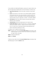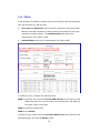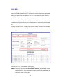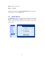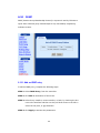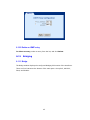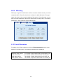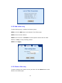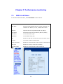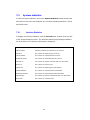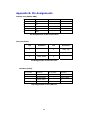
1
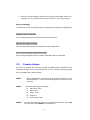
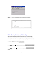
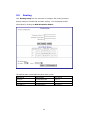
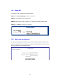
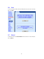
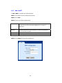
CT-500S
ADSL Router
User’s Manual
Version F1.0
8/19/2002
261031-002P
Preface
This manual is written for the following software version: AD6489 0814. It is
written for Web management. It is designed to provide information to network
administrators. It covers the installation, operation and applications of the ADSL
router.
Version Notes
This software was upgraded from software Version 0725, the following default settings have
been added:
1. For PPPoA (VC mux) PVC 8/65
2. For transparent bridging PVC 8/35
3. For RFC 1483 Routing PVC 87/80, WAN IP 172.16.1.1
4. DHCP (DNS 200.72.1.5)
Warning
Before servicing or disassembling this equipment, always disconnect all
power and telephone lines from the device.
Use an appropriate power supply and a UL Listed telephone line cord.
Specification of the power supply is clearly stated in Appendix A Specifications.
ii
Table of Contents
Part 1: Overview........................................1
Chapter 1 Introduction ...................................................... 1
1.1
Product Overview ................................................................ 1
1.2
Features ............................................................................ 1
1.3
Application ......................................................................... 2
1.4
Front Panel LED Indicators.................................................... 2
Chapter 2 Hardware Installation........................................ 3
2.1
Preparing for Installation ...................................................... 3
2.2
Installation ......................................................................... 4
Part 2: Console Management .................5
Chapter 3 Access by Console.............................................. 5
3.1
Conventions ....................................................................... 5
3.2
Console Access ................................................................... 6
3.3
Saving Parameters/ Rebooting .............................................. 7
Part 3: Web Management............................9
Chapter 4 Login via the Web Browser ................................ 9
4.1
IP Address.......................................................................... 9
4.2
Login Procedure ................................................................ 11
Chapter 5 Basic Configuration.......................................... 12
5.1
Change the Password......................................................... 12
5.2
ADSL Link Status............................................................... 13
5.3
WAN Setup....................................................................... 14
5.3.1
RFC 1483 Bridged.............................................................. 14
5.3.2
RFC 1483 Routed .............................................................. 16
5.3.3
PPPoE .............................................................................. 17
5.3.4
PPPoA.............................................................................. 19
5.3.5
MER ................................................................................ 20
5.4
LAN IP Address ................................................................. 21
5.5
Routing............................................................................ 22
5.5.1
Enable RIP ....................................................................... 23
5.5.2
Static route configuration ................................................... 23
5.6
Save................................................................................ 25
5.7
Reboot............................................................................. 25
5.8
Retrieve default settings..................................................... 26
iii
Chapter 6 Advanced Configuration................................... 27
6.1
ADSL Mode....................................................................... 27
6.2
NAPT (Port Translation) ...................................................... 28
6.2.1
Add a NAPT ...................................................................... 29
6.2.2
Flush NAPT Entries ............................................................ 30
6.3
DHCP............................................................................... 30
6.3.1
Enable DHCP .................................................................... 30
6.3.2
Disable the DHCP .............................................................. 31
6.4
Boot P/DHCP Relay ............................................................ 31
6.5
SNMP .............................................................................. 32
6.5.1
Modifying SNMP Parameters................................................ 33
6.6
Configure ......................................................................... 34
6.6.1
Configure Interface............................................................ 34
6.6.2
DNS & Default Gateway: .................................................... 36
6.6.3
NAT................................................................................. 37
6.7
VCC................................................................................. 38
6.7.1
List IPoA .......................................................................... 39
6.7.2
Delete Encapsulation.......................................................... 40
6.7.3
Add a VCC........................................................................ 40
6.7.4
Delete a VCC .................................................................... 42
6.7.5
Show VCC quality .............................................................. 42
6.7.6
PPPoE .............................................................................. 42
6.8
PPPoA.............................................................................. 43
6.9
MER ................................................................................ 43
6.10
IGMP ............................................................................... 44
6.10.1
Add an IGMP entry ............................................................ 44
6.10.2
Delete an IGMP entry......................................................... 45
6.11
Bridging ........................................................................... 45
6.11.1
Bridge ............................................................................. 45
6.11.2
Spanning tree ................................................................... 48
6.11.3
View STP parameters ......................................................... 48
6.11.4
To configure STP parameters .............................................. 49
6.11.5
Enable/Disable STP............................................................ 49
6.12
Filtering ........................................................................... 50
6.12.1
List of filter entries ............................................................ 50
6.12.2
Add a filter entry ............................................................... 51
6.12.3
Delete a filter entry ........................................................... 51
6.12.4
Modify a filter entry ........................................................... 52
6.12.5
Flush filter entries ............................................................. 52
Chapter 7 Performance monitoring .................................. 53
7.1
ADSL Link Status............................................................... 53
iv
7.2
System statistics ............................................................... 54
7.2.1
Interface Statistics ............................................................ 54
7.2.2
TCP-IP ............................................................................. 55
7.2.3
DHCP-Lease ..................................................................... 56
7.3
ATM statistics ................................................................... 56
7.3.1
AAL5 ............................................................................... 56
7.3.2
Encapsulation ................................................................... 57
Chapter 8 Diagnostics ...................................................... 58
8.1
OAM Loopback .................................................................. 58
8.2
Ping ................................................................................ 59
Chapter 9 Adding a PVC ................................................... 60
Appendix A: Specifications ............................................... 64
Appendix B: Pin Assignments ........................................... 66
v
vi
Part 1: Overview
Chapter 1 Introduction
This chapter introduces the ADSL Router. It includes a product overview,
description of the products features and applications, and explains the functions
of the Front panel LED indictors.
1.1
Product Overview
The ADSL Router utilizes an ADI chipset to meet the specific needs of multiple
users at small/home offices and remote /branch offices. It provides one 10/100
BaseT Ethernet port to connect to a LAN. It can access the Internet; Corporate
LAN; or Video on demand, over one ordinary telephone line; at speeds of up to
eight Mbps. In addition, it supports up to eight virtual concurrent-connections, to
multiple destinations. The ADSL Router has full routing capabilities to
segment/route IP protocol, and it is capable of bridging other protocols. The ADSL
Router has the speed and stability to be used for multi-media applications; and it
can easily be configured and monitored from a web-browser (Internet Explorer,
Netscape).
1.2
Features
The ADSL Router is compact and high performance standalone unit. It supports or
provides:
One 10/100 Base-T Ethernet port for LAN connection
Bridge/Routing function
Auto-negotiation rate adaptation
AAL5 for ATM over ADSL
UBR/CBR ATM services
VC-based and LLC multiplexing
Up to 8 VCs
Embedded SNMP agent and RFC MIB II
Web-based management
OAM F5
Static route/RIP/RIP v2 routing function
Dynamic IP assignment and Network Address Translation
1
1.3
Application
Figure 1-1 shows a possible application of the router.
PSTN
Micro filter
ADSL (G.DMT)
POTS splitter shelf
ADSL Router
POTS splitter
ADSL Router
ATM DSLAM
Figure 1-1 Application
1.4
Front Panel LED Indicators
LED
Color
Indicator
Power
Green
Alert
Red
LAN Link
Green
ADSL Link Green
ADSL Act
Mode Function
On
Power is supplied to the router
Off
Power is not supplied
Off
Normal operating status
On
The ADSL link is not established
On
An Ethernet link is established
Off
An Ethernet link is not established
Flash
Activity over the Ethernet link
Flash
ADSL link is training
On
An ADSL link is established
Off
ADSL link not established
Flash
Receiving or transmitting data over the
ADSL link
Off
Not receiving or transmitting data over the
ADSL link
Green
2
Chapter 2 Hardware Installation
2.1
Preparing for Installation
Installation requires the following equipment:
A VT-100 compatible terminal –
This terminal is essential to perform the initial configuration of the router.
Normally this is a terminal with a VT-100 emulation program, such as Telix.
An RS232 straight-through cable to connect to the Console PortAn RS232, DB9-to-DB9 straight-through cable is required to connect the terminal
to the device.
An AC power adapter cord to connect to the Power jackA suitable AC-to-AC power adapter cord is shipped with the device. It is used to
provide the necessary power for the device’s operation.
RJ45 10/100BaseT Ethernet connector cable to connect to the LAN port:
An RJ45 LAN connector cable is used to connect the router to the Local Area
Network (LAN). A cross-over cable is used to connect the router to a PC, and a
straight-through cable is used to connect to a hub. The pin assignments of the
RJ45 connector are listed in Appendix B.
An RJ11 connector cable to connect to the LINE port–
An RJ11 connector cable is used to connect the router to the telephone line from
the telephone company. Refer to Appendix B for the pin assignments of the RJ11
connector.
Clip-on stands
Your router is shipped with two clip-on stands. It is recommended that you affix
these to your router and operate the router in a vertical-upright position, in order
to optimize the performance of your router.
Optional POTS splitter or micro filter
Pots splitters or micro-filters are available if required.
3
2.2
Installation
Figure 2-2 illustrates connections to the router backplane connectors.
Figure 2-1 Installation
Caution: Always disconnect all telephone lines from the telephone wall-outlet
before servicing or disassembling this device.
STEP 1
Connect the power adapter to the power jack of the device, and
then plug the power adapter into the wall outlet.
STEP 2
Connect the LAN port to a PC with a cross-over RJ45 cable, or to
a hub with a straight-through RJ45 connector cable.
STEP 3
Connect the Console port to a VT-100 compatible terminal with
an RS232 straight-through cable.
STEP 4
Connect the LINE port to a POTS splitter or micro filter with an
RJ11 connector cable.
STEP 5
Affix the two clip-on stands to the bottom of the router and place
the router in an up-right position (this is strongly recommended
in order to optimize the router’s performance)
STEP 6
Turn on the power switch on the rear panel.
Note: If the device fails to power on, or it malfunctions, first verify that the
power supply is correctly connected, and then power it on again.
4
Part 2: Console Management
Chapter 3 Access by Console
This chapter will introduce console management, if you wish to use the web to
manage your device you should see Part 3 of this manual. The web section can
also be referenced for more complete explanation of some parameters and
procedures. In the first section of this Chapter, the conventions used by the
console and by this manual to explain the console will be discussed. The second
part of the chapter will explain how to establish access by console.
3.1
Conventions
Manual Conventions
1. Characters inside a box indicate that they are keys that need to be pressed.
For example, Enter, represents “push the Enter key.”
2. Text highlighted in gray, represents text that you may see on the screen.
For example, Press Y or N
3. The user interface has a multi-level menu structure, the following style will
be used to indicate menu locations: 1.Basic> 4. LAN IP This example
shows that the LAN IP screen can be accessed form the main menu by
entering the following keys: 1 Enter ; and then 4 Enter.
4. Numbers inside round brackets indicate a menu location. For example
(1.4), indicates 1.Basic> 4. LAN IP.
CLI Interface Conventions
1. Values in round brackets are default or previously entered values. For
example (Enabled), represents a default value or previously entered value
of “enabled”.
5
2. Values in square brackets represent the range of permissible values. For
example, [8~35], indicates that a value from 8 to 35 may be entered.
Pop-up messages
You are likely to see the following pop-up messages (messages are highlighted)
Mandatory, Enter Valid Value
This message indicates that a parameter must be entered.
Optional, Press Return To Skip
This message indicates that it is optional to enter a parameter.
Do You Wish To Submit These Values [Y/N] :
This message indicates that the entered parameters will be submitted.
3.2
Console Access
For access by console, the console PC should be installed with a standard VT-100
emulation program, such as HyperTerminal 5 or Telix. The following steps explain
how to establish the console session.
STEP 1
STEP 2
Start a standard VT-100 program such as HyperTerminal (Ver. 5 is
recommended), or Telix in the local terminal; and select an open
com port.
Enter the following port settings:
Baud rate: 9600
Data bits: 8
Parity: none
Stop bit: 1
Flow control: none
STEP 3
You will be prompted to enter a User name and Password, enter root
for User name and 12345 for the Password.
6
STEP 4
3.3
The first screen of the console interface will now display.
Saving Parameters/ Rebooting
After changing parameters, in order to ensure that they are retained after
rebooting or re-powering the router, you must save the parameters to flash
memory. These procedures can be performed by completing the following steps:
1. Enter the Basic menu, select 6. Save & reboot
2. Press Y to save, or N to not save at the prompt: Do you wish to save (Y/N)?
3. Press Y to reboot, or N to not reboot at the prompt: Do you wish to reboot
(Y/N)?
7
4. Upon completion, you will see the Success message displayed.
8
Part 3: Web Management
This section describes how to manage the router via a Web browser from the
remote end. You can use a web browser such as Microsoft Internet Explorer, or
Netscape Navigator. It is best to set your display resolution to 1024 x 768. To
change the resolution you can go to the Microsoft Windows control panel and click
on the Display icon, and change the display settings. You will find the display
settings there.
Chapter 4 Login via the Web Browser
4.1
IP Address
To log on to the device using a web browser, your workstation and the device
should both be on the same network segment. You can either modify the IP
address of your workstation to the same domain of the device, or modify the IP
address of the device to the same domain as your workstation.
You can modify the IP address of the device by using console mode (see Section
3.2), and follow the steps below:
STEP 1: Enter a console program and go to 1.Basic> 4. LAN IP
STEP 2: Change the IP address to the same domain as your workstation.
STEP 3: Save the settings to the flash and reboot the device.
Basic> 6.Save & reboot
STEP 4: Start your Internet browser with the new IP address.
You can modify the IP address of your PC by modifying its TCP/IP. Follow the steps
below:
STEP 1: Enter the TCP/IP screen and change the IP address to the domain of
192.168.1.x/24. You should choose an IP address from
192.168.1.132-192.168.1.254 to avoid conflict with IP addresses
reserved for the DHCP pool (192.168.1.3 to 192.168.1.131).
9
STEP 2: Click OK to submit the settings.
STEP 3: Start your Internet browser with the default IP address 192.168.1.1.
10
4.2
Login Procedure
To log on to the system from the Web browser, follow the steps below:
STEP1: Start your Internet browser.
STEP 2: Type the IP address for the router in the Web address field. For example,
if the IP address is 192.168.1.1, type http://192.168.1.1
STEP 3: You will be prompted to enter your user name and password. Type the
password, or if the password was not changed, type the default passwords. The
default USER name is root, and the default password is 12345.
STEP 4: After successfully logging in, you will reach the main menu.
11
Chapter 5 Basic Configuration
From the Basic menu bar you can change passwords, configure the WAN/LAN
interfaces, set-up routing, save settings, reboot the device, and retrieve the
factory default settings.
5.1
Change the Password
To modify the password, click Change Password from the menu bar. Type the
old password and type the new password twice. Click Apply to submit the
settings.
If you change the password, make sure you keep a record of it in a safe place, as
you will require it next time you log-on.
12
5.2
ADSL Link Status
To view the ADSL link status, click Link Status from the tool bar. The page
includes the following information:
ADSL Line Status
Shows the current status of the ADSL line
ADSL Mode
Shows the ADSL standard that is currently configured. The
standards are: MULTI, T1.413, G.DMT, and G.LITE.
Upstream
Upstream data rate negotiated by DSL link (Kbit/s)
Downstream
Downstream data rate negotiated by DSL link (Kbit/s)
Attenuation
Current attenuation (dB) of both near end and far end.
SNR Margin
Current SNR margin (dB)
HEC
Number of ATM cells received with errors, since start of link.
Firmware
The version number of the firmware
15 min ES counter
Number of errored seconds for the current 15 minute period
CRC errors
Number of errors per second since training
1 day ES counter
Number of errored seconds for the current day
13
5.3
WAN Setup
Click WAN Setup from the tool bar and configure the WAN interface for these
services: RFC1483 Bridged, RFC1483 Routed, PPPoE, PPPoA, and MER. The
following are the common settings to set up these services.
VPI and VCI
LLC Encapsulation: With LLC encapsulation, a link control header is added to
the Ethernet packet that identifies the protocol type (Ethernet). This allows
multiple protocols to be transmitted over the ATM Virtual Circuit.
VC Multiplexing: With VC Multiplexing, no link control header is needed as
the ATM Virtual Circuit is assumed to be carrying a single protocol.
Enable NAPT: NAPT or Network Address Port Translation is explained further
in section 6.2. This feature is available for RFC 1483 Routed, PPPoE, PPPoA,
and MER. It is enabled for PPPoE.
5.3.1 RFC 1483 Bridged
When using RFC 1483 style bridging, Ethernet frames are “bridged” over ATM
Virtual Circuits. The Ethernet frames are encapsulated using either LLC
Encapsulation or VC Multiplexing. With LLC encapsulation, a link control header is
added to the Ethernet packet that identifies the protocol type (Ethernet). This
allows multiple protocols to be transmitted over the ATM Virtual Circuit. With VC
Multiplexing, no link control header is needed as the ATM Virtual Circuit is
assumed to be carrying a single protocol. Since the Ethernet packets are bridged,
the router’s only responsibility is to pass the Ethernet packets to and from the
Internet Service Provider and the local network. The IP addresses of the local
network are assigned by the ISP either statically or dynamically.
To set up the RFC 1483 Bridged, configure the common fields on the top of the
page and click the Add button to add the entry.
14
To modify an entry, complete the following steps:
STEP 1: Select the entry from the Current ATM PVC List, at the bottom of the
WAN Setup page. The current values of the selected entry will display in
the upper section of the page.
STEP 2: Change the parameters.
STEP 3: Click Modify.
To delete an entry, Select it from the Current ATM PVC List, at the bottom of the
WAN Setup page, and click the Delete button.
15
5.3.2 RFC 1483 Routed
To set up the RFC 1483 Routed, configure the common settings on the top of the
page, click RFC 1483 Routed and configure the specific settings (WAN IP address
and WAN subnet mask). Click the Add button to add the entry.
To modify an entry, complete the following steps:
STEP 1: Select the entry from the Current ATM PVC List, at the bottom of the
WAN Setup page. The current values of the selected entry will display in
the upper section of the page.
STEP 2: Change the parameters.
STEP 3: Click Modify.
To delete an entry, Select it from the Current ATM PVC List, at the bottom of the
WAN Setup page, and click the Delete button.
16
5.3.3 PPPoE
PPPoE provides service providers similar billing and access control as present in
dial-up services. And with direct support to Ethernet it provides a low cost solution
to supporting multiple hosts at the customer premises. PPPoE provides session
authentication using either Password Authentication Protocol (PAP) or Challenge
Handshake Authentication Protocol (CHAP). Session accounting is possible and
conservation of bandwidth can be done by closing down unused sessions. By
utilizing PPP, link and network parameters are easily negotiated between the
IAD/Router and the ISP.
When using PPPoE, the system is assigned an IP address from the Internet
Service Provider as part of establishing the network connection. The system can
be configured as a DHCP server for its LAN and NAT can be used to translate
private addresses to public addresses. In this way, computers in the LAN do not
have to have their own public IP addresses.
17
To set up PPPoE, click PPPoE (NAT Enabled), configure the common fields on the
top of the page and the following fields. Click the Add button to add the entry.
User name/Password: used for the remote customers to login during
dialup.
Mode: Direct and Auto. If the mode is set to AUTO the PPPoE negotiation
automatically starts when the system identifies any traffic required to be
transferred on the link. When DIRECT is selected the PPPoE negotiation is
started manually using the “pppoestart” command. The default is DIRECT.
Idle Timeout: defines the period of idle time (minutes) after which the
PPPoE link will be terminated.
Authentication: defines the authentication code: PAP, and CHAP
Enable DHCP Server: enables the DHCP server. This field is automatically
checked when PPPoE is selected. Deselect the field to disable the DHCP
server. The DHCP server dynamically allocates network addresses and
delivers configuration parameters to hosts.
To modify an entry, complete the following steps:
STEP 1: Select the entry from the Current ATM PVC List, at the bottom of the
WAN Setup page. The current values of the selected entry will display in
the upper section of the page.
STEP 2: Change the parameters.
STEP 3: Click Modify.
To delete an entry, Select it from the Current ATM PVC List, at the bottom of the
WAN Setup page, and click the Delete button.
18
5.3.4 PPPoA
To set up PPPoA, click PPPoA, configure the common fields and the following fields.
Click the Add button to add the entry.
User name and Password: used for remote customers to login upon dialup.
PPPoA is manually activated by entering startup commands from the page:
Advanced>Configure PPPoA. The Authentication field defines the
authentication code: PAP or CHAP.
Authentication: defines the authentication code (PAP, CHAP).
To modify an entry, complete the following steps:
STEP 1: Select the entry from the Current ATM PVC List, at the bottom of the
WAN Setup page. The current values of the selected entry will display in
the upper section of the page.
STEP 2: Change the parameters.
STEP 3: Click Modify.
To delete an entry, Select it from the Current ATM PVC List, at the bottom of the
WAN Setup page, and click the Delete button.
19
5.3.5 MER
MAC Encapsulation Routing (MER) implements router features over RFC1483
bridged link. MER enables the ATU-R to send and receive IP packets encapsulated
as bridged frames with MAC address. The ATU-R runs with full router functions,
including NAPT, virtual server, RIP, DHCP, and so on. MER utilizes network address
translation (NAT) to allow multiple PCs with different private IP addresses on the
LAN to share a public IP addresses. The functions of NAT and allocation of an ATM
virtual channel improves the security of network access on the RFC 1483 Bridged
link.
To set up the MER service, configure the common fields, and the IP Address and
Subnet Mask fields that are highlighted on the screen. Click the Add button to add
the entry.
To modify an entry, complete the following steps:
STEP 1: Select the entry from the Current ATM PVC List, at the bottom of the
WAN Setup page. The current values of the selected entry will display in
the upper section of the page.
20
STEP 2: Change the parameters.
STEP 3: Click Modify.
To delete an entry, Select it from the Current ATM PVC List, at the bottom of the
WAN Setup page, and click the Delete button.
5.4
LAN IP Address
Click LAN Setup from the menu bar to configure the LAN IP address. Type the IP
address and subnet mask. Click Apply to submit the settings. When the new
IP address is applied, the Web configuration will be interrupted. Use the new IP
address to login.
21
5.5
Routing
Click Routing Setup from the menu bar to configure the routing functions.
Routing functions includes RIP and static routing. You can display the RIP
information by clicking the RIP information button.
The default static routes table has three static routes:
Network ID
Subnet Mask
Next hop IP
10.0.0.0.
255.255.255.252
10.0.0.1
10.11.1.0
255.255.255.255
10.11.1.2
192.168.1.0
255.255.255.0
192.168.1.1
22
5.5.1 Enable RIP
To enable the RIP, complete the following steps:
STEP 1: Click Routing Setup from the menu bar
STEP 2: Select On in the Rip Status field.
STEP 3: Select a RIP Version (Version 1 or Version 2) from the Version field.
STEP 4: Click Apply to submit the settings.
5.5.2 Static route configuration
The Routes Configuration field allows you to add, modify, and delete a static route.
Type the Destination Network ID, subnet mask, and next hop IP and click a button
below to perform the requested function.
23
Add:
To add a static route complete the following steps:
STEP 1: Click Routing Setup from the menu bar
STEP 2: Enter parameters for Destination Network ID, Subnet Mask, Next
Hop IP
STEP 3: Click the ADD button
Modify:
To modify a static route complete the following steps:
STEP 1: Select the entry you wish to modify from the List of Static Routes
STEP 2: Change the parameters
STEP 3: Click the Modify button
Delete:
STEP 1: Select the entry you wish to delete from the List of Static Routes
STEP 2: Change the parameters
STEP 3: Click the Delete button
24
5.6
Save
To save the settings to Flash, click Save & Reboot from the menu bar. In the main
pane, click Save.
5.7
Reboot
To reboot the router, click Save & Reboot from the menu bar. In the main pane,
click on Reboot.
25
5.8
Retrieve default settings
To retrieve the default settings, click Erase & Reboot from the menu bar. In the
main pane, click Erase.
26
Chapter 6 Advanced Configuration
6.1
ADSL Mode
There are four ADSL modes: MULTI, T1.413, G.DMT, and G.LITE. The default
ADSL mode is MULTI. MULTI mode enables the device to auto-adjust its mode to
match the remote CO DLSAM. You can specify an ADSL mode on this page, and
click the Apply button to submit the settings.
27
6.2
NAPT (Port Translation)
The discussion in this section is for port translation. For IP address translation,
refer to Section 17.1.2 WAN Interface. NAPT, also called overloading, is a form of
NAT that maps multiple Private IP addresses to a single Public IP address. PAT
allows several virtually addressed workstations to share a single global address.
PAT uses the TCP and UDP port numbers to map multiple virtual addresses to a
single global address.
Click NAPT on the Advanced menu bar to configure the NAPT (Network Address
Port Translation). If any NAPT entries have already been configured, they will
appear on the right side of the screen.
28
6.2.1 Add a NAPT
To add a NAPT, complete the following steps:
STEP 1: Click NAPT from the Advanced menu bar
STEP 2: Click Add.
STEP 3: Enter the following parameters:
Public Port
Enter the public port number. Any packet whose IP header
contains the specified destination port will be mapped or
redirected.
Protocol
Specifies whether the ports numbers for these arguments are
TCP or UDP port numbers.
Local Address
Enter the IP address of the machine on the local LAN.
Local Port
Enter the port number of the machine on the local LAN.
STEP 4: Click Apply to accept the parameters.
29
6.2.2 Flush NAPT Entries
To flush (delete) all NAPT entries click the Flush button on the NAPT screen.
6.3
DHCP
The Dynamic Host Configuration Protocol (DHCP) provides a centralized approach
to allocating IP addresses. It allows IP addresses to be dynamically assigned on
an as needed basis, from a pool of addresses. The DHCP function of the device is
disabled by factory default.
6.3.1 Enable DHCP
STEP 1: Click DHCP from the menu bar to configure the DHCP parameters.
STEP 2: Click Enable and fill out the following fields:
Starting IP Address: The first IP address of the address pool in the DHCP
server. Note the IP address should be in the same subnet as the router’s LAN
IP address.
End IP Address: The last IP address of the address pool in the DHCP server.
Note the IP address should be in the same subnet as the router’s LAN IP
address.
Gateway: The gateway IP address
Netmask: The subnet mask of the IP network
DNS: The IP address of the Domain Name Server
Lease Time (in Days): Upon login, the remote workstation will obtain an IP
address. This field defines the period of time that the workstation can use
this IP address to access the Internet.
STEP 3: Click Apply to submit the settings.
30
6.3.2 Disable the DHCP
STEP 1: Click DHCP from the menu bar to configure the DHCP parameters.
STEP 2: Click Disable.
STEP 3: Click Apply.
6.4
Boot P/DHCP Relay
The DHCP packet format is based on a BootP packet. As a result, DHCP uses the
BootP relay agent to forward DHCP packets. This scheme provides interoperability
between existing BootP clients and DHCP servers. The BootP relay agent uses the
same criteria and methods for forwarding both DHCP and BootP packets. The
DHCP Relay is disabled by default. To enable it complete the following steps:
STEP 1: Access the BootP/DHCP Relay screen by clicking on DHCP Server on
the Advanced Menu, and then click the BootP/DHCP Relay tab.
STEP 2: In the DHCP Relay field, select Enable.
31
STEP 3: Enter the IP Address of a numbered network interface that you want to
receive BOOTREQUEST or DHCP packets from clients.
STEP 4: Click on the Apply button.
6.5
SNMP
SNMP is a software entity that responds to information and action request
messages sent by a network management station. The messages exchanged
enable you to access and manage objects in an active or inactive (stored) MIB on
a particular router. To configure the SNMP parameters, click the SNMP button on
the Advanced menu bar. The window displays the SNMP parameters.
32
6.5.1 Modifying SNMP Parameters
To modify the SNMP parameters, click the Modify button at the bottom of the
screen. Click Apply to submit the settings.
33
6.6
Configure
From this page you can configure LAN and WAN interfaces, VCC, PPPoE, PPPoA,
DNS & Default Gateway, and NAT.
6.6.1 Configure Interface
To configure an interface, select it by clicking in the round-box on the left in the
screen. Then click on the Configure Interface button at the bottom of the screen.
Note the following:
Interfaces:
Interface mer0 usage is reserved; its status is always Down.
Interface lo0 is the loopback interface. When an OAM loopback is
performed, the status field displays UP.
Interfaces Atm1 to Atm 7 display the interfaces configured for RFC1483
Bridged mode or RFC 1483 Routed mode.
34
Interfaces pppo to ppp7 display the interfaces configured for PPPoE or
PPPoA.
Parameters:
Dynamic IP address from DHCP: Selects the IP address to be assigned by
the DHCP server.
Static IP address: Selects the IP address to be statically assigned.
Interface: The name of the interface currently selected.
IP address: The IP address of the selected interface.
Subnet Mask: The subnet mask of the selected interface.
MTU: Sets the maximum transmission unit of the interface. The MTU is used
to limit the size of packets that are transmitted on an interface. Not all
interfaces support the MTU parameter, and some interfaces, like Ethernet,
have range restrictions (80 - 1500).
Speed: Auto, 10 Mbps, or 100 Mbps
Status: UP and Down. When an interface is set to Down, the system will not
attempt to transmit messages through that interface. When set to UP,
messages can be transmitted through the interface.
The following is the screen shot for the LAN interface (eth0).
35
The following is a screen shot for the ATM interface.
6.6.2 DNS & Default Gateway:
To configure the DNS and default gateway, complete the following steps:
STEP 1: Click on Configure in the menu bar.
STEP 2: Click on DNS and default gateway at the bottom of the configuration
page.
STEP 3: Complete the fields below:
Domain Name: user-defined
Primary DNS server: Enter the primary server IP address.
Secondary DNS server: Enter the secondary server IP address that
will be used in the event that the primary server IP address fails or is not
available
Default Gateway: The gateway IP address of the IP network
36
STEP 4: Submit the settings by clicking Apply.
6.6.3 NAT
When NAT is enabled for a WAN interface, all private addresses are mapped to the
IP address of the specified WAN interface. To enable or disable NAT on an ATM
interface complete the following steps:
STEP 1: Click on Configure in the menu bar.
STEP 2: Click on NAT at the bottom of the configuration page.
STEP 3: Complete the fields described below:
Enable NAT Tick this box to enable NAT or leave it blank to disable it.
Interface Name select an interface from ATM 0 to ATM 7
STEP 4: Click Apply to submit the setting.
37
6.7
VCC
This screen lists all current VCC entries in the middle of the screen. From this
screen you can also: List IPoA, Delete Encapsulation, Add a VCC, Delete a VCC,
and Show VCC quality.
38
6.7.1 List IPoA
To list IP over ATM information click on the IPoA button at the bottom-left of the
screen.
The IPoA entry is set up from Advanced>Configure>VCC。 Click the Add button
on the List of VCC screen.
39
6.7.2 Delete Encapsulation
To delete encapsulation first select a VCC entry and then click the Delete Encap
button.
6.7.3 Add a VCC
To add a VCC entry, complete the following steps:
STEP 1: Click on the Add VCC button, the VCC screen will appear.
STEP 2: Enter values for the parameters (explained below).
STEP 3: Click the Apply button at the bottom of the page.
vpi:
Virtual Path Identifier (VPI) that identifies this ATM
connection. The vpi is integer numbers which can range
from 0 to 4095.
vci:
Virtual Channel Identifier (VCI) that identifies this ATM
connection. The vci is an integer number which can range
from 65,535.
Peak Cell rate
(cells/sec):
Defines the fastest rate a user can send cells to the
network. It is expressed in units of cells per second.
Average Cell rate
Defines the maximum sustainable/average rate a user can
send cells to the network. It is expressed in cells per
second. This specifies the bandwidth utilization. This value
must always be less than or equal to the Peak Cell Rate.
(cells/sec):
Burst size (cells):
Maximum number of cells the user can send at the peak
rate in a burst, within a sustainable rate.
CDVT (cells):
Constrains the number of cells the user can send to the
network at the maximum line rate.
Type:
Select data or voice
Service Type:
Supports real-time applications requiring a fixed amount
of bandwidth. The applications produce data at regular
intervals such as a video stream. The user can specify how
much bandwidth they wish to reserve.
cbr Constant Bit
Rate:
rtvbr Real Time
Variable Bit Rate:
Nrtvbr Non Real
Time Variable Bit
Rate:
Supports time-sensitive applications such as voice. In
these applications the rate at which cells arrive are varied.
Supports applications that have no constraints on delay
and delay variation, but still have variable-rate and bursty
traffic characteristics.
40
Ubr Unspecified Bit
Rate:
Best effort service that does not require tightly constrained
delay and delay variation. UBR provides no specific quality
of service or guaranteed throughput.
41
6.7.4 Delete a VCC
To delete a VCC entry, select the entry from the list of VCCs and then click on the
delete button, at the bottom-right of the page.
6.7.5 Show VCC quality
To view information regarding the VCC quality, click on the Show VCC Quality
button, at the bottom-right of the page.
6.7.6 PPPoE
This section will describe how to start, stop, delete, and set a default PPPoE entry.
To configure a PPPoE entry in more detail, refer to Chapter 9 Add A VC.
The PPPoE page can be accessed by clicking on Configure in the Advanced menu
bar. To start, stop, delete, or set as default a PPPoE entry first select the entry
from the List of PPPoE entries, and then click the corresponding button at the
bottom of the page.
42
6.8
PPPoA
This section will describe how to start, stop, delete, and set a default PPPoA entry.
To configure a PPPoA entry in more detail, refer to Chapter 9 Add A VC.
The PPPoA page can be accessed by clicking on Configure in the Advanced menu
bar. To start, stop, delete, or set as default a PPPoA entry first select the entry
from the List of PPPoA entries, and then click the corresponding button at the
bottom of the page.
6.9
MER
This section will describe how to configure, enable, disable, or delete a MER entry.
The ATU-R supports one MER entry (named mer0). To configure a MER entry in
more detail, refer to Chapter 9 Add A VC.
The MER page can be accessed by clicking on Configure in the Advanced menu
bar, and click the MER’s tab.
The page allows configuring, enabling, disabling, or
deleting a MER entry. The Enable button displays when no MER entry is
established or when mer0 is disabled. If a MER entry was established, the Disable
button displays on the screen.
43
6.10
IGMP
IGMP (Internet Group Membership Protocol) is a protocol used by IP hosts to
report their multicast group memberships to any immediately neighboring
multicast routers.
6.10.1 Add an IGMP entry
To add an IGMP proxy, complete the following steps:
STEP 1: Select IGMP Proxy, from the menu bar.
STEP 2: Click Add at the bottom of the screen.
STEP 3: Select Proxy interface, router interface, or both, by checking the box
next to the interface and then use the pull-down menu to the left to
select the eth, atm, or ppp Interface.
STEP 4: Click Apply to activate the parameters.
44
6.10.2 Delete an IGMP entry
To delete an entry, select an entry from the list, and click Delete.
6.11
Bridging
6.11.1 Bridge
The Bridge window displays the configured Bridging PVC entries of the interfaces.
There are four buttons at the bottom of the main-pane: Group Info, Add PVC,
Flush, and Disable.
45
GroupInfo: This configures the LAN packets that will travel through the LAN
interface to the selected WAN interfaces. If you wish to change the interfaces
that are configured you must first click on the Flush button (to remove the
current ocnfiguration), and then click on the Group Info button, select the
group interfaces and then click the Apply button. You must select eth0, as
eth1 is not enabled for this product version.
46
AddPVC: You can add a PVC to the ATM interface. From the Bridging
screen, select an ATM interface Vpi, Vci and Encapsulation type and then click
Apply.
Flush: Selecting this command from the Bridging screen, will flush all PVC
entries.
Disable: Selecting this command from the Bridging screen, will disable the
PVCs but retain the parameters, so that they can be enabled at a later point.
47
6.11.2 Spanning tree
To access the spanning tree menu click the Spanning Tree tab, located at the top
of the Bridging screen.
6.11.3 View STP parameters
To view the STP parameters, click the STP parameters tab, located at the
bottom of the Spanning Tree screen.
48
6.11.4 To configure STP parameters
STEP 1: click the Spanning Tree tab, located at the top of the Bridging screen.
STEP 2: Click the Configure Port button.
STEP 3: Configure the parameters.
STEP 4: Click the Apply button.
6.11.5 Enable/Disable STP
If you wish to Enable/Disable a STP entry, select the entry and then click the
Enable or Disable Button, which is located at the bottom-right of the Spanning
Tree screen. Note that if the entry is already enabled the Disable button will be
present. Conversely, if the entry is disabled then the Enable button will be
present.
49
6.12
Filtering
Filtering is a type of firewall that is useful to increase network security or to limit
unwanted traffic. Filters for this device are based on MAC addresses. The page
opens with a list of the currently configured filter entries. From this page, you can
also view Filter Parameters, add a filter, delete a filter, modify a filter, or flush filter
parameters. These functions are described below.
6.12.1 List of filter entries
To display a list of filter parameters click the Filter parameters button at the
bottom of the Filters page. The following parameters are displayed:
Maximum filter entries
The number of filter entries that can potentially be set
Total filter entries
The number of filter entries that are currently set
Total static entries
The number of static entries that are currently set
Total dynamic entries
The number of dynamic entries that are currently set
50
6.12.2 Add a filter entry
To add a filtering entry, complete the following steps:
STEP 1: Click the Add button at the bottom of the Filters page.
STEP 2: Enter the MAC address
STEP 3: Set the Frame to forward to forward packets which match the MAC
address, or Drop, to drop matching packets.
STEP 4: Click Apply
6.12.3 Delete a filter entry
To delete a filtering entry Select an entry and then click the Delete button at the
bottom of the Filters page.
51
6.12.4 Modify a filter entry
To modify a filter select the entry and then click the Modify button at the bottom
of the Filters page.
6.12.5 Flush filter entries
To flush all the filtering entries, click the Flush button at the bottom of the Filters
page.
52
Chapter 7 Performance monitoring
7.1
ADSL Link Status
To view the ADSL link status, click Link Status on the tool bar.
ADSL Line Status
Shows the current status of the ADSL line
ADSL Mode
Shows the ADSL standard that is currently configured. The
standards are: MULTI, T1.413, G.DMT, and G.LITE.
Upstream
Upstream data rate negotiated by DSL link (Kbit/s)
Downstream
Downstream data rate negotiated by DSL link (Kbit/s)
Attenuation
Current attenuation (dB)
SNR Margin
Current SNR margin (dB)
HEC
Number of ATM cells received with errors since start of link.
Firmware
The version number of the firmware
15 min ES counter
Number of errored seconds for the current 15 minute period
CRC errors
Number of errors per second since training
1 day ES counter
Number of errored seconds for the current day
53
7.2
System statistics
To view the system statistics, click on the System Statistics button located near
the bottom of the menu-bar. Statistics are recorded regarding Interfaces, TCP-IP,
and DHCP-Lease.
7.2.1
Interface Statistics
To display the interface statistics, click the Interface tab, located at the top-left
of the System Statistics screen. The Interface Statistics page displays statistics
for all interfaces. The following information is displayed:
Interface Name
The name of the interface
Admin Status
Indicates whether the interface is Up or Down
Octets In
The number of Octets (bytes) recieved
Unicast PktsIn
The number of unicast packets received
Broadcast PktsIn
The number of broadcast packets received
Discards In
The number of packets received that were discarded
Errors In
The number of inward errors
Octets Out
The number of Octets (bytes) transmitted
Unicast PktsOut
The number of unicast packets transmitted
Broadcast PktsOut
The number of broadcast packets transmitted
Discards Out
The number of packets transmitted that were discarded
Errors Out
The number of outward errors
54
7.2.2 TCP-IP
To view TCP-IP statistics click on the TCP-IP tab at the top of the System
Statistics page. The TCP-IP page displays the IP statistics, UDP statistics, TCP
statistics, and ICMP statistics.
55
7.2.3 DHCP-Lease
To view TCP-IP statistics click on the DHCP-Lease tab at the top of the System
Statistics page. The DHCP-Lease page shows the PCs that obtained an IP address
from the DHCP pool.
7.3
ATM statistics
Click on ATM Statistics on the menu-bar to display the ATM Statistics. The ATM
Statistics page monitors information for AAL5 and Encapsulation.
7.3.1 AAL5
The AAL5 page shows the AAl5 statistics.
56
7.3.2 Encapsulation
Click on the SNDCP tab to display encapsulation statistics. This page displays the
VCs that are running. (SNDCP stands for sub-network dependency convergency
protocol).
57
Chapter 8 Diagnostics
To access the Diagnostics screen, click the Diagnostics button, which is located
on the menu bar. The Diagnostics screen has two test functions: OAM Loopback
and Ping test.
8.1
OAM Loopback
STEP 1: click the Diagnostics button, on the menu bar.
STEP 2: Click the Loopback tab on the Diagnostics screen.
STEP 3: Enter the following information to run the OAM loopback:
Flow type: F5 SEG (Segment to Segment) and F5 ETE (End-to-End). The
SEG loopback is from ATUR to DSLAM. The ETE loopback is from ATUR to the
ISP RAS.
VPI and VCI: Specify the virtual channel that will run the OAM loopback.
Loopback ID: Type the loopback pattern for the loopback
STEP 4: Click the Start Loopback button at the bottom of the screen.
58
8.2
Ping
A Ping test is used to verify the status of a network connection after the RIP or
static route function is enabled. Ping sends a request message to the host and
waits for a return message. This diagnostic function can verify if the remote host
is reachable. Ping can also measure the round-trip time to the remote host.
To access the Ping test screen, click the Ping tab on the Diagnostics screen.
Enter the Host Name or IP address of the remote terminal and click Submit to
start the ping and display the results.
The following is an example of the ping result. The information displayed is as
follows:
Packets transmitted
The number of packets that were transmitted
Packets received
The number of packets that were received
Packets lost
The number of packets lost
Minimum round trip time
The fastest round-trip time
Maximum round trip time
The slowest round-trip time
59
(transmitted-received)
Chapter 9 Adding a PVC
STEP 1: Click Configure from the Advanced menu bar.
STEP 2: Click the VCC tab.
60
STEP 3: Click Add
STEP 4: Configure the parameters on this page and click Apply to submit the
settings.
STEP 5: Save the settings and reboot the device.
61
STEP 6: Click Bridging on the Advanced menu bar.
STEP 7: Click the GroupInfo button.
STEP 8: Specify the interfaces that data will be transmitted to the Internet from
the LAN port (eth0). The item eth0 must be checked, and also check the
ATM interface (s) that data can be forwarded from the LAN interface.
STEP 9: Click Apply to submit the settings.
62
STEP 10: Return to the previous page and click AddPVC.
STEP 11: Type the VPI and VCI values that were established in Step 4, and select
an Encapsulation type. Click Apply to submit the settings.
STEP 12: Return to the previous page and select an bridging entry from the List
of entries, and click Enable to enable the PVC.
63
Appendix A: Specifications
WAN interface (one ADSL port)
Item
Specifications
ADSL standard
DMT
G.DMT data rate
Downstream: 8 Mbps
Upstream: 1 Mbps
ATM attributes
Item
Specifications
PPP over AAL5
RFC2364
Multi-protocol over AAL5
RFC2684 (1483)
VCs
8
AAL type
AAL5
ATM service class
UBR/CBR/VBR
ATM UNI support
UNI 3.1 PVC
OAM F4/F5
Yes
Management
Item
Specifications
Console port
RS232/DB9
SNMP
Yes
TR-006 ADSL line MIB
Yes
Telnet
Yes
Web-based management
Yes
Configuration backup and restoration Yes
LED indicators
ADSL status, LAN status, Power
64
Local interface (1 port Ethernet Switch)
Item
Specifications
Standard
IEEE 802.3 10/100BaseT
Transparent bridging and learning
Yes
Routing functions
Item
Specifications
IP static route
Yes
RIP and RIPv2
Yes
Network functions
Item
Specifications
ARP
Yes
DNS, NAT/PAT, DHCP/BOOTP
Yes
PAP, CHAP
Yes
Power supply
Item
Specifications
Power source
110 VAC or 220 VAC (50 or 60 Hz)
Environmental conditions
Item
Specifications
Operating temperature
0 to 50 degrees Celsius
Relative humidity
5% to 90% (non-condensing)
65
Appendix B: Pin Assignments
Console Port (RS232 DB9)
Pin number
Definition
Pin number
1
NC
6
2
TD
7
3
RD
8
4
NC
9
5
GND
Pin Assignments of the Console Port
Line port (RJ11)
Pin
Definition
Pin
Definition
1
-
4
ADSL_TIP
2
-
5
-
3
ADSL_RING
6
-
Pin Assignments of the RJ11 Port
LAN Port (RJ45)
Pin number
Definition
Pin number
Definition
1
Transmit data+
5
NC
2
Transmit data-
6
Receive data-
3
Receive data+
7
NC
4
NC
8
NC
Pin assignments of the LAN Port
66