1
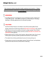
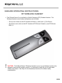
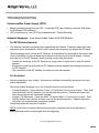
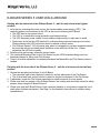
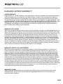
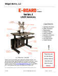
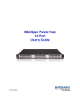
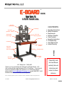
TM USER MANUAL Universal Mounting Plate CONTENTS Tilt Assembly Tilt Actuator (backside - hidden) UPS / CPU Mounting Support Uniterruptible Power Supply Box Mantel Cross Beam RF Wireless Handset Retracting Extension Power Cord Operating Instructions Safety Precautions Requirements Features / Benefits Crate Contents Assembly Instructions Troubleshooting User Walk-Around Limited Warranty Vertical Actuator Swivel Caster s Sub-Frame Assembly ! Please fully read this User Manual U.S. Patent No. 7,640,866 Thank you for purchasing the E-Board by Widget Works, LLC Set-up should take approximately 30 to 45 minutes. If you should have any questions about the product or for technical support, please email [email protected] or call (864) 621-1444 between the hours of 9:00am and 5:00pm EST. carefully, follow all instructions and retain it for future reference. Errors – descriptive, typographic, or pictorial – are subject to correction. Specifications are subject to change without notice. 14-10-28 Email: [email protected] Series 5 – LA31 RF 1 This manual contains important safety warnings and cautions. Please read and follow all instructions carefully during assembly and operation of the E-Board. ! WARNING: ! CAUTION: The E-Board Series 5 is designed to mount a Flat Screen with a weight not to exceed 250 pounds. Total additional weights to E-Board Series 5, including amenities, in the Box Mantel are not to exceed 20 pounds. Read this E-Board Series 5 User Manual, the UPS (Uninterruptible Power Supply) Instructions & Flat Screen Manual BEFORE PLUGGING IN this machine. Take time to look over the machine to locate the labels marked “Pinch Points” and familiarize yourself and others with the controls BEFORE PLUGGING IN & OPERATING this machine. When placing next to a wall or other furniture, allow at least a two (2) inch open buffer space to prevent possible operational obstructions or pinch points. The casters have locking mechanisms to prevent moving during use. Please take a moment to locate labels marked “Pinched Points” and familiarize yourself and others with the controls before continuing. 2 E-BOARD OPERATING INSTRUCTIONS RF WIRELESS HANDSET The E-Board Series 5 is controlled by a Radio-Frequency (RF) Wireless Handset. The Wireless Handset control button descriptions are as follows: The top row in black on the RF Handset will Raise (˄) and Lower (˅) Flat Screen The bottom row in white on the RF Handset will Tilt Screen Forward (˅) and Tilt Screen Back (˄) ! CAUTION: The E-Board Series 5 Wireless Handset is not a toy and children should not be allowed to play with the actuator controls. It is important to keep this out of reach when children are present. See Step 2 in the Assembly Instructions for children safety considerations. 3 ! E-BOARD SAFETY PRECAUTIONS CAUTION: The E-Board Series 5 is designed to mount a Flat Screen with a weight not to exceed 250 pounds. Total addition weights to E-Board Series 5, including amenities, in the Box Mantel are not to exceed 20 pounds. At no time should any person sit or lean on the EBoard Series 5. CAUTION: When placing the E-Board Series 5 near a wall or other furniture, allow at least a two (2) inch open buffer space to prevent possible operational obstruction or pinch points. The casters have locking mechanisms to prevent moving during use. CAUTION: With the mounted Flat Screen, check ceiling clearance, water sprinkler heads and hanging light fixtures before operating E-Board Series 5. If clearance is an issue, the E-Board Series 5 controller is programmable to include limits on actuators. (Contact Widget Works for details) CAUTION: Do not attempt to lift the E-Board Series 5 with a Flat Screen mounted. If lifting is required, remove Flat Screen and lift from the Sub-Frame only, do not lift while gripping a hold of Box Mantel. CAUTION: Take time to look over the E-Board Series 5 to locate the labels marked “Pinch Points” and familiarize yourself and others about these locations. CAUTION: The E-Board Series 5 was not designed to be used on any raised platform, incline or slope. CAUTION: When moving the E-Board Series 5, always lower the Flat Screen to its lowest level to ensure your safety. CAUTION: The E-Board Series 5 120 volt power plug, when not plugged in to a power receptacle should be protected with the provided plastic protective cover and kept off the floor. Please remember the UPS has a battery. CAUTION: The E-Board Series 5 is not a toy and children should not be allowed to play with the actuator controls. This unit has a wireless handset, it is important to keep this out of reach when children are present. See Step 2 in the Assembly Instructions for children safety considerations. CAUTION: When moving the E-Board Series 5 on a ramp, special care should be taken so that the machine will be safely controlled at all times. It is always recommended that at least two persons perform this operation. CAUTION: The E-Board Series 5 is not designed for outdoor use. CAUTION: The E-Board Series 5 is not designed for use around any type of water. CAUTION: The E-Board Series 2 is not design to be transported in any vehicle without being adequately secured and/or with the Flat Screen mounted to the machine. 4 REQUIREMENTS Standard power specifications of 60 Hertz (50 Hertz if applicable) For integration of computers with at least 128 MB video card and at least 1920x1080 resolution capability. FEATURES / BENEFITS RF Wireless Handset for actuator movements Height adjustments with Powered Vertical Movement from 28” through 55” at Box Mantel Beam Flat Screen with Powered Angular (Tilt) Movement with 15° front tilt and 5° back tilt Engineered for ease of movement - Foot print area: Depth 33” x Width 43” (not including Flat Screen) - Swivel Twin Wheel Casters allow for ease of mobility (four-wheel locking for increased stability) - Approximately 325 Lbs. without flat screen and computer/peripherals Integrated tubing electrical enclosures for cables and cords, eliminating clutter Uninterruptible Power Supply (UPS) for surge protection and battery backup UPS/CPU Mounting Support for power supply, computer(s) and other peripherals (a patented design feature allows for a single external power cord for operation) Universal Mounting Plate for 50” to 90” Flat Screen with VESA (MIS) standard patterns – provides vertical adjustment for clearance between Flat Screen and Box Mantel for user comfort. (Maximum Flat Screen weight 250 lbs.) Stained wood storage box mantel for wireless handset, user manual and flat screen devices Frame color: Matt black on all surfaces Video Cable – HDMI or Display Port User manual (minimal assembly required (includes fasteners and tools for mounting of Flat Screen) Standard power specifications of 60 Hertz (50 Hertz if applicable) Controller for the actuators is programmable (provides customizable height and tilt adjustments range control – contact Widget Works, LLC for details) E-Board Series 5 Limited Warranty for two (2) years from date of purchase 5 E-BOARD – CONTENTS E-Board Series 5 - assembled Widget Works - Carton S5 (14” x 10” x 4”) with the following: E-Board User Manual RF Handset Parts Bag “C5” for mounting Flat Screen Two (2) – M6 Threaded Studs (M6 x 50 mm long) Two (2) – M8 Threaded Studs (M8 x 50 mm long) Two (2) – M6 Wing Nuts Two (2) – M8 Wing Nuts Six (6) – M6 Button Head Screws (M6 x 16 mm long) Six (6) – M8 Button Head Screws (M8 x 20 mm long) One (1) – 2.5 mm Allen Wrench One (1) – 3 mm Allen Wrench One (1) – 4 mm Allen Wrench One (1) – 5 mm Allen Wrench One Lot - Wire Ties 12” Strap Rip Tie All-Purpose Strap Four (4) – ¼” Center Labels 1” Wide x 36” Length Elastic Hook & Loop Clinching Strap (for Mini Computer) HDMI Video Cable UPS Manual and Accessories Extension cord 6 ASSEMBLY INSTRUCTIONS ! Before getting started, fully read the Operating Instructions and the important Safety Warnings. STEP 1 Locate Widget Works Carton 14104. In this carton is the Uninterruptible Power Supply with battery backup (UPS) instruction sheet, please take a moment to read. Review your Voltage-Amps (VA) and Watt (W) ratings for all the equipment that is going to be mounted to the E-Board Series 5 to ensure the UPS is properly sized for the electrical loads. STEP 2 Also located in Carton 14104 is an extension cord, locate the E-Board Series 5 common receptacle plug on the Sub-Frame Assembly, plug in the extension cord. Plug the extension cord into a power outlet and turn on the UPS unit. The E-Board Series 5 now has power. ! CAUTION: The following safety options should be considered when children are using this device or are in the area during its usage. This is not a toy, as covered earlier in the “Safety Warnings”. Option 1 – Located under the Cross Beam (reference cover photo) on the left side (looking from the backside of the E-Board) locate the Control Box, the E-Board power receptacle plug (tagged with fluorescent yellow cable tie) can be unplugged after the adjustments to the E-Board Series 5 are made for the user. This will stop power to the all actuators to ensure unaccompanied children may not operate the unit. Option 2 – At the Control Box is a receiver cable (also tagged with fluorescent yellow cable tie) for controlling the RF Wireless Handset, which can also be unplugged; this accomplishes the same purpose as Option 1. NOTE: Both options may be utilized for additional safety precautions. STEP 3 ! ! Before operating, reference the E-Board Series 5 – Operating Instructions on page 3. CAUTION: Before going to the next step make sure the E-Board Series 5 is on a level surface and the four casters are locked. WARNING: The E-Board Series 5 is designed to mount at Flat Screen with a weight not to exceed 250 pounds. Total additional weights to E-Board Series 5, including amenities, in the Box Mantel are not to exceed 20 pounds. 7 STEP 4 ! STEP 5 Read your Flat Screen User Manual before proceeding. Use your Flat Screen manufacturer’s directions for picking up the Flat Screen. In preparation for the remaining steps, review the Flat Screen User Manual’s section related to vertical (wall) mounting. Follow the manufacturer’s steps for removing the stand from the Flat Screen, if applicable. For reference, the Flat Screen User Manual will also give you the Flat Screen mounting pattern and screw size. CAUTION: For correct installing, mounting and uninstalling of the Flat screen, it is strongly recommended to use a trained person(s) with knowledge and experience in the vertical (wall) mounting of flat screens. Failure to follow correct procedures may result in damage to the equipment or injury to the installer. Flat Screen Universal Mounting Plate Preparations: The Universal Mounting Plate has already been fastened to the Tilt Assembly at the lowest adjustment for shipping. This plate has ¾” vertical adjustment increments to allow for clearance between the Mantel Box top surface and the bottom of the Flat Screen. It is recommended that you leave 2 to 3 inches of clearance to avoid possible pinching when the Flat Screen angular (tilting) adjustment is activated, also keeping in mind clearance for the lid opening on the Mantel Box. NOTE: The Universal Mounting Plate has different size clearance holes for the different size screws to be used. Choose the proper size hole for the screw to be used, the largest holes receive M8 screws, smaller holes receive M6 screws. NOTE: User may want additional clearance for any other desired Mantel Box peripherals. To find the height clearance adjustment that’s right for user, consider the following steps: 1. On the backside of the Flat Screen, locate the lowest mounting positions and measure from this position to the bottom of the Flat Screen. Using this measurement, add the 2 to 3 inches recommended (as noted above). Keep this “Totaled Number”. 2. On the E-Board be sure the Tilt Assembly is fully retracted (leaned back) reference Figure 2 on page 11. 3. On the Universal Mounting Plate, locate the mounting pattern that matches the Flat Screen mounting pattern and note the lowest mounting positions. 4. Check the “Totaled Number” to see if adjustment of the Universal Mounting Plate is necessary. If needed, loosen the four (4) Universal Mounting Plate M8 Flat Head Screws with provided 5mm Allen wrench; adjust the vertical position to the closest matching mounting position using the “Totaled Number”. THIS STEP REQUIRES AT LEAST TWO PEOPLE! Read the additional NOTES on next page before starting this step. 8 NOTE: For convenience, located in Widget Works Carton 14104 (in Parts Bag “C5”) are two (2) M8 Threaded Studs / Wing Nuts that can be used by removing the top two (2) M8 Flat Head Screws first and installing the two (2) M8 Threaded Studs / Wing Nuts. This allows support for the Universal Mounting Plate before removing the two (2) bottom M8 Flat Head Screws making the Universal Mounting Plate adjustment easier. NOTE: Make sure to use the same four (4) tapped holes on the Tilt Assembly when adjusting the Universal Mounting Plate. SPECIAL NOTES: If the Universal Mounting Plate will not adjust high enough – simply rotate the Universal Mounting Plate one hundred and eighty degrees (180°) for new range of higher adjustments restart this Step at Item 3. Should the Universal Mounting Plate need to be lowered more than the allowed adjustments, there is a provision to do this. Locate the four (4) yellow covered setscrews on the Tilt Assembly. Remove these setscrews with 4mm Allen wrench and place each of these setscrews into one of the current tapped holes. Make sure these setscrews are flush with mating surface. When finished, you now have lowered the Universal Mounting Plate adjustments approximately two (2) inches, restart this Step at Item 3. 5. Once the Universal Mounting Plate is re-located, be certain that all four (4) M8 Flat Head Screws for the Universal Mount Plate are secured. STEP 6 Once again, located in Parts Bag “C5” is the following: Threaded Studs, Wing Nuts, Button Head Screws and Allen Wrenches (these are provided for mounting the Flat Screen to the E-Board). NOTE: Again, your Flat Screen User Manual will also give you the Flat Screen mounting pattern and screw size. SPECIAL NOTE: Should part of the flat screen mounting pattern go behind the UPS unit, remove the Stop/Lock (round plastic knob) mounted directly on top of the UPS. Lifting up to remove the UPS unit, move to the center area on the UPS/CPU Mounting Plate and temporarily secure with furnished strapping. Once the flat screen is mounted and secured, re-mount the UPS unit. Re-attach the Stop/Lock making sure to rotate clockwise so that it is tight against UPS. Make sure the Stop/Lock fastener is secured. 9 STEP 7 Referencing information from both Steps 4 through 6, use the proper Threaded Studs / Wing Nuts provided from Parts Bag “C5”. By hand, screw in the two (2) Threaded Studs, as far as possible into the two top vertical (wall) mounting locations in the back of Flat Screen as shown in photo – Figure 1. Wall Mounting Locations Figure 1 ! CAUTION: Before going to the next step make sure the E-Board is on a level surface and the four casters are locked. 10 STEP 8 Be certain that the Tilt Assembly is retracted (leaned back) – Figure 2. Use the RF Handset, by pressing the white “Tilt Screen Back” button (˄) referenced in the “EBoard – Operating Instructions” on page 3 to make this adjustment. Figure 2 ! WARNING: The E-Board Series 5 is designed to mount a Flat Screen with a weight not to exceed 250 pounds. Total addition weights to E-Board Series 5, including amenities, in the Box Mantel are not to exceed 20 pounds. 11 STEP 9 ! Use your Flat Screen manufacturer’s directions for picking up the Flat Screen. Gently insert the Threaded Studs into the proper matching top mounting holes in the Universal Mounting Plate on the E-Board as shown – Figure 3. (REQUIRES AT LEAST TWO PEOPLE!) CAUTION: THIS STEP REQUIRES AT LEAST TWO PEOPLE! With two people holding the Flat Screen in this position they can align the Treaded Studs into the correct mounting holes and then thread the two (2) corresponding Wing Nuts onto ends of the Threaded Studs to prevent the Flat Screen from sliding forward while securing proper screws. Figure 3 STEP 10 Install two (2) proper sized Button Head Screws through the Universal Mounting Plate and into the lower Flat Screen (wall) mounting locations. Once the two (2) lower Button Head Screws are started, secure, but not tighten with the appropriate Allen Wrench, one at a time, remove each top Wing Nut/Threaded Stud replacing them with the proper sized Button Head Screw. A person may need to lift up on the threaded stud side of the flat screen to relieve the screen weight to remove stud. Be certain that all Button Head Screws for this Flat Screen mounting are now secured. STEP 11 Consult the Flat Screen User Manual for connecting the power cord, video cable and other cables as instructed. Reference any additional peripheral user manual(s) for cords and cables at this time. NOTE: Additional power cord(s), video cable or other cables with extra length can be stowed in the Cross Beam’s open cavities. 12 STEP 12 Plug in the power cord from the Flat Screen into the surge-protected-only side of the UPS. STEP 13 Figure 4 references the UPS/CPU Mounting Support from the back side and also the Electronics Support located to the left. The UPS/CPU Mounting Support has a horizontal area to the left for mounting a desktop CPU. The vertical surfaces have mounting patterns with fasteners for mounting a compact CPU (two locations) and on the horizontal surface of the Electronic Support for mounting a wireless gateway. Figure 4 NOTE: There is a vertical cut out on the back left side of the Cross Beam to stow the AC Adapter for the compact CPU. Again, any extra length of the cable and cord can be stowed in the Cross Beam. STEP 14 Plug the CPU power cord into the battery back-up side of the UPS. If peripherals have been added, plug related power cords into the appropriate side of UPS. STEP 15 Plug video cable and all other user peripherals into the CPU and Flat Screen. STEP 16 It is recommended at this point to do a start up. Turn on all the equipment. The Flat Screen may need to be set to a particular “Picture Setting” and/or other settings for specific needs. Reference the appropriate user manual for any issue(s). An IT person may be helpful for additional software applications. 13 STEP 17 The E-Board assembly is now finished. We recommend reading the “E-Board Series 5 User Walk Around” on page 16 to identify most of the design details that the E-Board Series 5 has to offer. NOTE: Lastly, there will be extra assembly items remaining due to Flat Screen variations, we recommend keeping the extra items (Screws, Threaded Studs, Spacers, etc.) in a safe place along with the E-Board Series 5 User Manual. With the Universal Mounting Plate for Flat Screens and other designs built-in to the EBoard, updating with new electronic components may be done with ease. 14 TROUBLESHOOTING Uninterruptible Power Supply (UPS): Beeping sounds coming from the UPS – review the UPS User’s Manual under the “Definitions for Illuminated LED Indicators”. UPS not performing – see UPS User’s Manual under “Trouble Shooting” Actuator Stoppage: (user cannot raise, lower or tilt Flat Screen) For RF Wireless Handset The Wireless Handset is activated when assembling the E-Board. Please be aware that other equipment (such as doorbells), which use the same radio-frequency can disturb the RF signal. Should stoppage occur, locate the RF Receiver, a small plastic box mounted on the bottom side of the Cross Beam (on the left hand side looking from the front side of the E-Board). Activate the reset key on the RF Receiver (small opening on right side) as follows: Activate the reset key on the RF Receiver by using a pen or similar item to keep the button pressed. Keeping the reset key activated; the RF Handset must be activated by pressing any button on the RF Handset. Upon activation of the RF Handset; the reset key must be released. For Actuators Actuator stoppage is very unlikely. Actuators are initialized at assembly and should not need further adjustment. Should an unlikely stoppage occur, the Controller must be reset as follows: Vertical Movement - Press the black “Lower (˅) Flat Screen” button once or twice. Then, hold the button down until the actuator runs into the end stop position. Release the button only when the movement has completely stopped. Angular (Tilt) Movement - Press the white “Tilt Screen Back (˄)” button once or twice. Then, hold the button down until the actuator runs into the end stop position. Release the button only when the movement has completely stopped. Doing these steps will reset the Controller. NOTE: If the button is released before the sequence is complete, then the initialization is interrupted and must be started again from the beginning. Email: [email protected] 15 E-BOARD SERIES 5 USER WALK-AROUND Starting with the back side of the E-Board Series 5 – with the unit raised to the highest position 1. Let’s start by reviewing the power source, the uninterruptible power supply (UPS). The retracting power cord connected to the UPS is the only cord leaving the E-Board. The UPS has its own power button. The UPS is a combination surge protection and battery backup. The UPS has extra power outlets for any addition components you may want to install. Please also know that the UPS has built-in indicators that produce a beeping sound code. Please reference the UPS instruction sheet for details on these codes. The E-Board Series 5 120 volt power plug, when not plugged into a power receptacle should be protected with the provided plastic protective cover and kept off the floor. Please remember the UPS has a battery. 2. Note the pinch point areas, reference the two labels. 3. The Universal Mounting Plate for the Flat Screen has the VESA standard design and nonstandard patterns for fitting most Flat Screens. 4. There is a vertical adjustment for clearance between the Mantel Box and Flat Screen bottom if needed. Finishing with the front side of the E-Board Series 5 – with the unit lowered to the half way position 1. Review the operating instructions for the E-Board The raise and lower control buttons in black for vertical adjustment of the Flat Screen The tilt front and back control buttons in white for angular movements of the Flat Screen 2. If applicable, review the Flat Screen manufactures owner’s manual for more details. 3. Please note that four casters of the E-Board Series 5 are locking and should be locked for safety reasons when using the E-Board Series 5. 4. Please note that the E-Board Series 5 has a wireless handset, it is important to keep this out of reach when children are present. See Step 2 in the Assembly Instructions for children safety considerations. 16 E-BOARD LIMITED WARRANTY LIMITED WARRANTY Widget Works, LLC (“WWK”) warrants to you, the purchaser, that when operated and maintained according to instructions attached to or furnished with the E-Board Product (“Product”) will be protected from defects in material and workmanship during the Warranty Period, subject to the terms and conditions set forth herein. The “Warranty Period” is two (2) years from the date the Product is purchased by the original purchaser. THIS LIMITED WARRANTY IS EXCLUSIVE AND IS IN LIEU OF AND EXCLUDES ALL OTHER WRITEN OR ORAL WARRANTIES OR CONTRACTUAL AGREMENTS, WHETHER EXPRESS OR IMPLIED BY LAW OR OTHERWISE, INCLUDING IN THIS EXCLUSION THE IMPLIED WARRANTIES OF MERCHANTABILITY AND FITNESS FOR A PARTICULAR PURPOSE. WARRANTY EXCLUSIONS WWK does not warrant that the Product will meet your specifications or needs. You acknowledge that you are solely responsible for the selection of the Product and determining the suitability of the Product for your needs. WWK is not responsible for damage arising from failure to follow instructions relating to the Product’s use. This Limited Warranty does not apply to: (a) damage caused by accident, alteration, abuse, misuse, flood, fire, earthquake or other external causes; (b) damage caused by operating the Product outside the permitted or intended uses as described by WWK; (c) cosmetic damage, including but not limited to scratches and dents, that does not otherwise affect the Product’s functionality or materially impair its use. In no event will WWK be liable, whether as a result of breach of contract, warranty, tort (including negligence) or other grounds, for special, consequential, incidental, liquidated or punitive damages including, but not limited to, loss of profits or revenue, loss of use of the Product, cost of capital, cost of substitute product, facilities or services, downtime costs, or claims of customers of the user of the Product for such damages. WARRANTY SERVICE, EXCLUSIVE REMEDY WWK will be solely responsible for determining whether or not the Product is defective. If a defect in the Product arises and a valid claim is received within the Warranty Period, WWK will, at its option, either (1) repair, or designate a service company to repair, the defect at no charge, using new, refurbished or rebuilt replacement parts, (2) replace the Product with Product that is new, refurbished, rebuilt or which has been manufactured from new or serviceable used parts, and that is at least functionally equivalent to the original Product, or (3) refund the purchase price of the Product upon its return. WWK may request that you replace defective parts with user-installable parts that WWK provides in fulfillment of its warranty obligation. Repaired or replacement parts or Product will be covered by this Limited Warranty for the balance of the Warranty Period. Defective Product and parts will become the property of WWK. This paragraph states WWK’s sole and exclusive obligation and liability and your sole and exclusive remedy under this Limited Warranty. WWK shall not be responsible for a failure to provide warranty services due to causes beyond WWK’s control. WWK shall not be responsible for related Flat Screens or Computers, etc.; any Limited Warranty on those products or other accessories is provided by the related manufacturer. WARRANTY CLAIMS Claims under this Limited Warranty must be reported to WWK during our normal business hours at the following number: 864-621-1444 or by e-mail at [email protected] or by contacting your authorized dealer/ distributor. 17 NOTES: 18