1
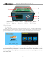
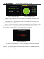
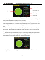
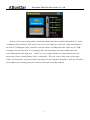
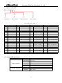
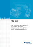
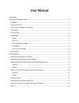
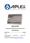
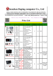
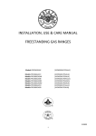
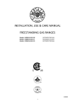
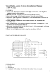
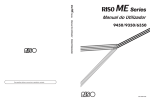
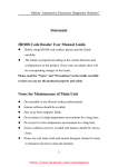
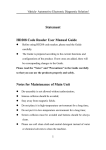
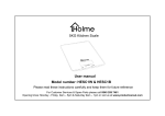
ASunDar User Manual ASD911 USB Cable Tester VR:1.0 Shenzhen ASunDar Electronics Co., Ltd www.asundar.com Shenzhen ASunDar Electronics Co., Ltd. Introduction Thank you for purchasing products made by Shenzhen ASunDar Electronics Co.,Ltd. The user manual tells you how to use the ASD911 USB cable tester correctly (ASD911 USB tester is shorted for ‘the tester’ in the user manual). Please read this user manual carefully before use. Attentions Please check below items when open the carton: ① If the tester model is what you ordered. ②If all enclosures including the tester certification, user manual and warranty bill are enclosed. ③ If any problem to occur during delivery such as broken,missing,damage or other defect, please contact our company or your supplier promptly. Please check if the voltage of power supply is within allowed range before power on. If it is beyond the range of voltage, it may make the tester unable to work and even burned out. Please make sure that the power supply meets the safety specification, otherwise there may cause electric shock accidents! With continuously improving for product, the manual will be revised based on product upgrade or specification change. If there is any difference with product usage , please look up latest version of the manual or contact our customer service staff. When you have any question about our product, please call our customer service staff for help. Service hotline:+86-755-28531900 400-0755-308 -1- Shenzhen ASunDar Electronics Co., Ltd. Contents I、Product Introduction -------------------------------------------------------------------------3 II、Technical Specification----------------------------------------------------------------------3 III、Quick Start -----------------------------------------------------------------------------------3 IV、Condition Requirements -------------------------------------------------------------------8 V、Warranty Agreements -----------------------------------------------------------------------9 -2- Shenzhen ASunDar Electronics Co., Ltd. I : Product Introduction This tester is mainly used for testing quality of USB cable, and applicable for many digital cables with UBS2.0, D-type port, Min USB and Micro USB port. Function & Feature Using 32 bit ARM,high speed processor USB assembly unit with separate design, easy to replace Measure the resistance of USB cable accurately Can be set the upper and lower limits of cable resistance. It helps choose qualified USB cables through resistance value needed by yourself. It can find the fault reason (short circuit, open circuit, core misconnection), and help for repair. Automatically test after inserting the USB cable, then quickly tells the test result with sound indicating and displaying on the color screen at the same time. It can identify at once that the USB cable is a digital cable with 4cores inside or a charging cable with 2cores inside. Test delay time can be set manually. II : Technical Specification Item Parameter Resistance testing range 1mΩ-1000mΩ Resistance 1mΩ Resistance 0.5% Voltage Range AC220V±10% Frequency Range 50Hz Tester Size HxWxD 76mm*150mm*176mm Packaging Size HxWxD 145mm*265mm*230mm Net Weight 1.25Kg Total Weight 1.85kg Cable impedance Readback Resolution Readback Accuracy(@25°C) Power Input Weight Specification III : Quick Start This chapter will give you a simple introduction for the basic function of the tester. It makes you understand and use the tester quickly. 3.1 The functions introduction on the tester panel -3- Shenzhen ASunDar Electronics Co., Ltd. ② ① ③ ⑦ ④ ⑤ ①left port(micro usb mini usb USB2.0) ②right port(USB2.0 ③up key ⑥left key ④right key ⑤ down key D-type) ⑥ ⑦ LCD display 3.2 Basic Operation 3.2.1Quick Start: Firtly, connect the power to the tester and switch the power on , and then LCD will show turned-on display, as shown in picture 1. Wait the system initializing for a few seconds, the tester goes into the standby status as shown in pircture 2. then the tester finishes its turn- on successfully. picture1: turn-on display picture2 standby screen As shown in picture 2, there are three function options. Through pressing left key for 2 seconds goes to setting status as shown in picture 3. Pressing right key goes to testing status as shown in picture 3. Click the up,down, left and right key can choose parameter on the menu by moving cursor when you enter a setting status. -4- Shenzhen ASunDar Electronics Co., Ltd. picture 3 digital cable setting picture 4 charging cable test As shown in picture 3, there are three items for setting. You can choose the upper limit or lower limit resistance for setting . As showed in picture 4 , when finishing the setting , it may begin the test . The resistance values can be set according to your different need. We advise to set the “delay test time” as default 1S or more than 1S for a stable connection of cable. In the setting interface , press the up and down key to move cursor, press the left key to return to the previous interface, press the right key to enter the setting interface (see picture 5) . Picture 5 setting interface The interface as shown in picture 5 , press left and right key to move cursor accordingly. Press the up or down key , the value located in cursor will be changed by one unit toward up or down respectively. When pressing right key for 2seconds, parameter setting will be confirmed and then you can continue to make a next setting. -5- Shenzhen ASunDar Electronics Co., Ltd. ①cable actual resistance p ②1A voltage drop ⑤result ③2A voltage drop ④error code picture 6 Digital cable testing As shown in picture 6, when connecting the USB cable in a test situation , the test will begin and the test results will be shown on the display screen immediately. If the actual resistance value is within the setting range , the tester will give a buzz sound and display green color in the circle , it means the test pass. If the actual value is beyond the setting range , the tester will give three times of buzz sounds and display red color in the circle, it means the test failure . The texts on the right screen show actual values.The top line shows actual resistance of single charging cable. The second and third line show the voltage drop with 1A and 2A current conducting separately. The fourth line shows the error code of cable(see details in table 1).If the code is 0000, it shows USB cable is accepted. You can press right key for retesting again. Pressing left key will return to standby situation. Pressing left key for 2seconds will enter setting situation. Picture 7 Picture 7 shows the test of charging cable without digital cable’s D+ and D-. The operation is the same as digital cable test. -6- Shenzhen ASunDar Electronics Co., Ltd. Picture 8 Automatic test Picture 8 shows auto testing which can identify whether the cable is digital cable(with D+,D- cable) or charging cable(without D+ &D- cable). You can see two USB icons on the left . After test finished, if the icon of “USB Digital Cable” turns blue color, the cable is a USB digital cable. If the icon of ‘USB Charging Cable becomes blue, it is a charging cable. The long shape icon in the middle shows the current through the cable right now. If there is no any change with the two icons and also the tester buzzes three times, it means that the cable is a bad cable . The error code of cable shows on the right corner , the fourth line , and you can check the details of error through seeing table 1. And now if needed, press right key for retesting again, press left key will return to standby situation -7- Shenzhen ASunDar Electronics Co., Ltd. 3.2.2:Error code rules Error code: X X X X A B C D ↓ ↓ ↓ ↓ misconnection open circuit resistance short circuit Error Code Table(Table 1) A Code B Description Code C Description Code D Description Code Description 0 Ok 0 Ok 0 OK 0 Ok 1 Bigger resistance 1 ------ 1 V+ wrong 1 V+ open circuit 2 ------ 2 D-wrong 2 D- open circuit 3 V+& D- 3 V+ wrong、D-wrong 3 V+ open、D- open 4 ------ 4 D+ wrong 4 D+ open circuit 5 V+&D+ short circuit 5 V+ wrong、D+ wrong 5 V+ open、D+ open 6 D-&D+ short circuit 6 D- wrong、D+ wrong 6 D- open、D+ open 7 V+&D- 、D+ hort circuit 7 V+、D-、D+ wrong 7 V+、D-、D+ open circuit 8 ------- 8 V- wrong 8 V- open circuit 9 V+&V- short circuit 9 V+ wrong、V- wrong 9 V+ open、V- open A D-&V- short circuit A D- wrong、V- wrong A D- open、V- open circuit B V+&D-、V- short circuit B V+、D-、V- wrong B V+、D-、V-open circuit C D+&V- short circuit C D+ wrong、V- wrong C D+ open、V- open D V+&D+、V- short circuit D V+、D+、V- wrong D V+、D+、V-open circuit E D-&D+、V- short circuit E D-、D+、V-wrong E D-、D+、V-open circuit F All short circuit F All lines wrong F All open circuit IV : Condition Requirements Item short circuit Parameter Specification Temperature 0°C-55°C Work condition Humidity Dust Altitude Storage condition Max: 85% Pollution level 2 Under 2000 meters Temperature -30°C~70°C Humidity Max: 90% -8- Shenzhen ASunDar Electronics Co., Ltd. V : Warranty Agreements 1.One year warranty since the purchasing date(according to issued receipt date). 2.It is out of warranty scope in below situation: A. Damage caused by improper delivery , use or storage such as liquid invasion, dampened, compressed, fallen, etc after purchase. B. Repair or remake not approved by our company C. Damage caused by natural disaster, such as the thunder and lightning, earthquake, fire, floods, etc.Fault or damage caused by other factors not by machine itself. D. Only with warranty certificate or purchase document. E. The accessories are out of warranty scope. 3.Once the tester has any problem or is damaged on occasion , please fill in the Warranty Certificate correctly for warranty and give it to us as soon as possible. 4.Please keep the Warranty Certificate well. If missed, it can not be provided again usually . 5.After warranty period, we provide repair service in charge to meet customer’s demand. 6.As for repair cost ,please refer to latest revision ‘Repair Price List’of our company. 7.If you have any question, please contact the local agents or contact our company directly. 8.Shenzhen AsunDar Electronics Co.,Ltd. reserves the right to interpret this agreement. Shenzhen ASunDar Electronics Co., Ltd. Company address: Fourth Floor of Building B, Hongshengyuan Industry Park,No.339 of Bulong Road, Bantian,Longgang District, Shenzhen, China Telephone:+86-755-28531900 Fax:0755-28530909 Website:www.asundar.com -9-