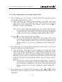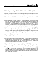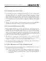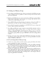
1
Programmable Power Supply Series User Manual
Programmable Power Supply Series User Manual
Table of Contents
Chapter 1 Summarization.........................................................1
Chapter 2 Safety and Precautions...............................................2
Chapter 3 Instructions on Panel of Instrument..........................3
3-1 Front Panel
3-1-1 Figure of Front Panel
3-1-2 Five Parts of Front Panel
3-1-3 Composite function key
3-2 Instructions on Rear Panel
3-3 Instructions on Bottom Panel
3-4 Instruction for Upper Part of Product
Chapter 4 Instructions on Operations......................................13
4-1 Preconditions for Start-up
4-2 Control over Output Function of DC Power Supply
4-3 Setting over Output Voltage(C.V)
4-3-1 Fine Adjustment over Output Voltage Value
4-4 Setting over Upper Limit of Output Current Value(C.C)
4-4-1 Constant Current (C.C)State
4-4-2 Overcurrent Protection(OCP)
4-4-3 Fine Adjustment over Value of Output Current
4-5 Setting over Memory Group
4-5-1 Use of Setting Value of Memory Group
4-6 TRACK Setting
4-7 Remarks
Chapter 5 Connecting Use of Output Function......................24
5-1 Instructions on Single and Double Groups of DC Output
5-2 Instructions on Double Groups of DC Output in Series: Output
VO= V1 + V2
5-2-1 Use Instruction on DC Output Positive and Negative Voltage
5-3 Instructions on Double Groups of DC Parallel Output: Output IO
= I1 + I2
Programmable Power Supply Series User Manual
Table of Contents
Chapter 6 Computer Remote Control Instructions.....................27
6-1 PC Communication Interface
6-2 Communication Parameters
6-3 Control Instruction
6-3-1 Inquiry about System Edition
6-3-2 Inquiry about specifications of output voltage and current of
machine
6-3-3 Resetting System
6-3-4 Force system to enter into or leave “remote control mode” and
inquiring about the start-up state of remote control mode
6-3-5 Compulsively lock system’s panel keyboard or unlock and
inquire the locking or unlocking state of keyboard
6-3-6 Leave or shut off all power outputs and inquire that whether
the power output is on or off
6-3-7 Set output voltage
6-3-8 Synchronous Setting over Multi-group Voltage (TRACK)
(Merely Applicable to Products with More than two groups
of Programmable Power Supplies)
6-3-9 Inquiry about the Setting Value of Current Output Voltage
6-3-10 Inquiry about Measured Value of Voltage Current Output
6-3-11 Constant Output Current
6-3-12 Inquiry about Setting Value of Current Output
6-3-13 Inquiry about Measured Current Value Current Output
6-3-14 Inquire about the current output state of power supply, in a
C.V or C.C state or during Voltage Adjustment
6-3-15 Inquiry about the List for Remote Control Instructions
6-4 Use Examples
Programmable Power Supply Series User Manual
WARRANTY
Leaptronix provides one year’s guarantee for parts and assembly from the
date of product delivery. In case any flaw actually emerging during the
guarantee period, Leaptronix will provide materials and repair the product
with such flaw; however, consumables are not within the guarantee range.
To obtain services provided by this guarantee, customers should, at the
beginning of guarantee period, inform Leaptronix through following
manners:
(1) Completely fill in the contents in the guarantee card of product fax it to
Leaptronix.
(2) Inform service center personnel of Leaptronix of various contents in the
product gurantee card completely by telephoning.
And make arrangement for the services to be provided. In case of a guarantee
need, customers should properly pack and deliver the defected product to
the agent or distributor service center, with freight paid by themselves. In
case that customers and Leaptronix service center are in the same country,
Leaptronix shall be liable for the back freight for mailing the product back to
customers. Or customers should bear all freight, customs duties, tax and any
other expense.
This guarantee is inapplicable to any flaw, malfunction or damage caused by
customers’ improper use, or improper or insufficient maintenance. During the
guarantee period, Leaptronix shall not provide services in event of following
circumstances:
(1) Damage caused by mounting, maintenance or service conducted by others
rather than representative of Leaptronix.
(2) Damage caused by improper use or connection with incompatible
equipment.
(3) Any damage or function abnormity caused by adoption of materials not
belong to Leaptronix.
(4) Amendment or integration with other products rises the difficulty or
lengthen the time of providing service.
This guarantee is provided by Leaptronix. Leaptronix shall not take any
guarantee responsibility for deal or resale with special purpose. Repairing
or replacing defected products is a remedial measure for rights and interests
of customers during the guarantee period. Leaptronix shall bear no any
responsibility for indirect, special, occasional or consequential damage, no
matter pre-reminder is available or not.
Programmable Power Supply Series User Manual
WARRANTY
Components or subassemblies of the machine body are expendable accessories
and should not be listed in the guarantee scope. Customers should, within
30 days dating from the purchase date, check whether there is any flaw on
components and subassemblies and, if any, immediately present it to the
agent appointed for sales, attached with the component or subassembly for
replacement it with new one.
List for Expendable Components or Subassemblies.
●
DC output line set
●
USB Cable
(Parts are USB interface module)
●
AC power line
●
RS-232 Cable
(Parts are RS-232 interface module)
Programmable Power Supply Series User Manual
Chapter 1 Summarization
To provide an optimum power supply resolution in the industry and reach
a best effective application of electric power, Leaptronix, with its years of
accumulated R&D experience and new technologies, design out mPP (Mini
Programmable DC Power Supply) & LPP (Programmable Linear Power
)series. Compared with the traditional power supply, mPP & LPP series
enjoys advantages such as a mini volume, a high resolution, guarantee of
items such as OVP/OCP/V.SET Limit/Key Lock, simple and convenient use
and strong function.
Aimed at the requirement of automatic test, most of products of this
series are equipped with RS-232 control interface, which enable users, via
application of simple and pellucid literal orders, write control program
easily for automatic control; in addition, DEMO software enclosed
with the product may be operated under a PC Windows environment,
possessing advantages such as remote control, program output, condition
judgment over PASS/FAIL, strong function of record, display and analysis
of current/voltage altering waveform and application in items such as
research/test/quality control/warming up by users.
At the same time, Leaptronix guarantee that each instrument has, prior to
delivery, been conducted optimization test and adjustment. It is, however,
hoped that you, ahead of use, check related accessories and matching parts
and peruse the direction for use and precautions so as to realize the optimum
performances and use state of the instrument. In case of any technical
support need, please telephone or e-mail to Leaptronix and we would serve
you with all sincerity.
-1-
Programmable Power Supply Series User Manual
Chapter 2 Safety and Precautions
All operations, maintenance and repairing services should be subject to
following safety precautions. Our company shall bear no responsibility
over any unpredictable phenomenon rising from any failure to accord with
precautions presented by this manual.
A. Prior to use of this power supply, please confirm that the output of AC
voltage is correct and that correct fuse has been mounted properly.
B. This product possesses protective grounding terminal(s). Therefore, please
do adopt three-conductor power line and ground the product properly.
C. During use of this product, please guarantee that there is enough
heat-emission space and air ventilation around the product so as to
prevent the damage or property shift resulting from failure of product in
normal heat emission.
D. Combustible articles should be kept away from this product so as to
avoid the danger caused by high temperature resulting from long time of
high-power work.
E. Operations and use of this product is strictly prohibited implemented
around combustible gas or flame.
F. Merely those fuse meeting requirements on aspects of voltage, current and
constant specification can be used on this product.
G. Operators do not dismantle the external shell of this product for use,
adjustment or replacement of internal parts and components so as to
avoid any wrong operation over this product or danger of an electric
shock.
WARNING!
This warning sign means that a personal injury may happen
if operators fail to follow the right operation methods or
procedure. Continuous use is not allowed unless operators
actually know of the operation procedure.
CAUTION!
This caution sign means that danger should be paid attention.
A damage of product may happen if operators fail to follow
the right operation methods or procedure. Continuous use is
not allowed unless operators actually know of the operation
procedure.
-2-
Programmable Power Supply Series User Manual
Chapter 3 Instructions on Panel of Instrument
3-1 Front Panel
3-1-1 Figure of Front Panel
1. Single output (Take mPP Single output for Example)
Display cresset of
remote control state
LCD display
Working light of
constant current
Working light of
constant voltage
mPP-3040S
Digit index of voltage
fine adjustment
Reminder of
keyboard locking
Setting key for current
Switch key for
output ON/OFF
Setting key for voltage
Number and function keys
V.SET
Limit
OVP
OCP
BEEP
Key Lock
Fixed
Fixed ON/OFF
Fixed
Leave key for
returning back to last layer
Rotary encoder
RECALL
Digit index of mobile voltage
fine adjustment(editing state:
delete the last character/figure)
STORE
Ascending key for fine
adjustment of output
voltage
Descending key for fine
adjustment of output voltage
DC output terminal
-3-
Programmable Power Supply Series User Manual
2. Double Power Line
A. mPP Double output
Setting key for voltage
Setting key for current
LCD Display
Switch key for Output ON/OFF
Rotary encoder
Switch setting for
OUT-1/OUT-2
DC output terminal
B. LPP Series Double output
-4-
Number and function keys
Programmable Power Supply Series User Manual
3-1-2 Five Parts of Front Panel
1. DC output terminal
Red and black respectively stands for positive and negative terminals of
power supply. Products with different types has output terminal with
different group counts.
2. LCD Display
It is the main information display area and used for display items such as
measured numerical values of voltage and current in present work and
settings input by user. Size and character of LCD alter in accordance with
types of product.
3. LED State
It refers to LED used to display states of items such as remote mode,
constant-current work and constant-voltage work.
“Remote”: LED for remote control state
“C.C”: LED for state of constant-current work
“C.V”: LED for state of constant-voltage work
Note: Partial types of this product shall integrate state display into LCD.
4. Rotary encoder
It is used to fine adjustment over output voltage under C.V mode and shall
switch to that over current under C.C mode.
-5-
Programmable Power Supply Series User Manual
5. Control key
Setting key for voltage:
It is used to set or change the value of output value
needed.
Setting key for current:
It is used to set or alter the output upper limit value of
current (Constant Current) needed.
Turn on or close all DC output terminals (including Fixed
OUTPUT).
Leave key:
Return back to last layer.
Output state:
It is used for digit index of mobile voltage fine adjustment.
Key is used to delete the last character or enter into setting
over fine adjustment.
Single output:
Descending key for fine adjustment of voltage value .(it is
used for fine adjustment over current under C.C mode.)
Double output:
Switch selecting voltage of OUT-1 / OUT-2 or current
setting.
Single output:
Descending key for fine adjustment of voltage value. (it is
used for fine adjustment over current under C.C mode.)
Double output:
Switch selecting voltage of OUT-1 / OUT-2 or current
setting.
-6-
Programmable Power Supply Series User Manual
3-1-3 Composite function key (it is a function key under a general model and
a number key while input materials.)
STORE
RECALL
BEEP
Memory function key:
It is used to store setting values concerning voltage and
current into memory of system. To realize this target, one
can only pressing down this key and then key in the target
memory code via number keys. Memory volume alters in
accordance with types of products. Product possessing
Fixed Output shall store Fixed output voltage and
whether turn on into the memory together.
Recall memory function key:
pressing down such key and then key in the code of
memory to be called via number keys can take out and
set the voltage and current materials of this group. In
case that the system is currently in an OUTPUT ON
state, then the voltage and current output shall alter
immediately. Product possessing Fixed Output shall take
out Fixed output voltage and whether turn on into the
memory together.
Humming ON/OFF switch key:
pressing down this key can switch humming of system
into on or off state. On state (sound available) is pre-set
after the product is started up.
-7-
Programmable Power Supply Series User Manual
Key�Lock
V.SET
Limit
OVP
Keyboard lock-up function key:
pressing down this key and then [0] or [1] key to select
OFF or ON state respectively can lock up all function keys
(including rotary encoder) except for [OUTPUT ON/OFF]
and KeyLock[5], which is used to avoid wrong settings
over voltage/current or improper operations; pressing
down this key again can unlock the keyboard locking. This
function can be automatically stored in the memory and
the locking or unlocking state of last time can be available
after the start-up of product next time. This function dost
not overlap with remote control instruction “:SYS:KL”
;therefore, if the latter one is locked by this key, it can not
be unlocked by “:SYS:KL OFF” instruction; and adoption
of “:SYS:KL ON” instruction shall lead to the invalidity
of all keys. Apart from the “:SYS:KL OFF” instruction
via external remote control, it can merely be unlocked via
manner of start-up again.
V.SET Limit function key:
pressing down this key and then key [1] to select ON state,
and then key in the highest voltage value limiting the
values can input by users. It is used to put limitations on
pressing [Voltage] key or voltage fine adjusted by rotary
encoder while providing power to articles to be tested with
a low voltage so as to avoid the damage may caused by a
voltage value higher than that the article to be test can
bear. System will automatically store the setting into the
memory and the setting of V.SET Limit of last time will
be available after the start-up of product next time.
Over voltage protection(OVP) setting function key:
pressing down this key and then [1] to select the ON
state, then key in the voltage value for over voltage
protection(OVP)so as to check, during an output state,
check an abnormal high voltage occurring to the DC
output terminal (reason of such phenomenon may be
that a short circuit occurs to a external higher voltage or
POWER itself loses control because of a circuit failure).
In case of a voltage value higher than the one set by OVP,
system will cut off the output, automatically enter into
OUTPUT OFF state and give out a warning; system will
store the setting of OVP into memory. Note: voltage value
of OVP should be higher than that of C.V (the voltage
value set by pressing [Voltage]).
-8-
Programmable Power Supply Series User Manual
Over current protection (OCP)set function key: pressing
down this key and then [1] to select the ON state, then key
in the voltage value for over current protection. It is used
to check the current consumption of article to be tested.
In case that current consumption is higher that the value
set by OCP, system will cut off the output, automatically
enter into OUTPUT OFF state and give out a warning
(for instance, you can set OCP as 1A and C.C current as
1.5A. Under such circumstance, if the current of article
to be tested is higher than 1A, then system will disconnect
the power supply for protection rather than enter into
constant current state in general); system will store the
setting of OVP into memory. Note: set current value of
OCP should be lower than that of C.C (the current value
set by pressing [Current]).
OCP
Fixed�ON/OFF
Fixed
Fixed
Fixed voltage (Fixed Output) output ON/OFF function
key: pressing down this key will separately switch between
turn-on and turn-off of fixed voltage output. Switch is
unavailable by pressing down this key under OUTPUT
OFF state. This function is merely available to those
products possessing a “fixed voltage output” specification.
Fixed voltage (Fixed Output) output voltage selection
key: pressing down this key can switch the voltage value
output by output terminal of fixed voltage. Voltage scope
for switch alters with types of products. Switch of voltage
setting is still available under Fixed OUTPUT OFF state.
After switch to ON state by pressing Fixed ON/OFF[2],
new voltage value will be output directly. Fixed Output
voltage selection: setting will be automatically store into
memory after switching back to ON state by pressing
Fixed ON/OFF[2] for convenience of automatic setting at
the time of start-up of product next time. This function
is merely available to those products possessing a “fixed
voltage output” specification.
Number keys: they are used to input numerical values
during setting over voltage, current, memory or other
materials. Pressing [▕←] can delete last character, at this
time, [ESC] are beyond editing function, return to last
layer and press [Enter] can complete the input function.
-9-
Programmable Power Supply Series User Manual
3-2 Instructions on Rear Panel
Rearposed panel is composed of AC input, fuse, power switch, USB
port, (partial products are RS-232 port) and heat-emission mechanism.
Caution:
During use of this product, please guarantee that there is enough
heat-emission space and air ventilation around the product so as to
prevent the damage or property shift resulting from failure of product in
normal heat emission.
-10-
Programmable Power Supply Series User Manual
3-3 Instructions on Bottom Panel
Bottom of product possesses AC voltage switch (for some products, it
may be on the rear panel) and heat-emission holes.
Caution:
Prior to use of this product, please do confirm the local AC voltage and
correctly select voltage value so as to avoid the damage of product or
burn of fuse.
-11-
Programmable Power Supply Series User Manual
3-4 Instruction for Upper Part of Product
This product possesses a carrying handle and heat-emission holes. For
products of some types are rather heavy; therefore, please avoid intense shake
or long time of tension during carrying; please be careful during carrying of
this product to avoid danger caused by a drop of product.
-12-
Programmable Power Supply Series User Manual
Chapter 4 Instructions on Operations
4-1 Preconditions for Start-up
1. Put this product on table stably, reserve enough heat-emission space and
guarantee a good ventilation environment around it and keep combustible
articles away from it.
2. Please confirm that local AC input voltage meets specification and
operation scope of product and that AC voltage switch at bottom of
product (or rear part) is on the correct position.
3. After confirming that the power switch is on the off state, insert AC
line into AC socket, switch on the power switch. At this time, system
will implement start-up setting and then give out a short buzzing; and
LCD will display the voltage value set in last time and emerge a “--ALL
OUTPUT OFF--” message. LEDs of both C.V and C.C fail to lighten.
4. DC output terminal is in a Output OFF state and there is no voltage
output.
-13-
Programmable Power Supply Series User Manual
4-2 Control over Output Function of DC Power Supply
1. Confirm POWER is in the Output OFF state in advance, and then
correctly set the voltage and current needed by the article to be tested and
connect the DC output line(s) in line with polarity to the power input point
of article to be tested firmly (for a load of larger current confirm joints are
connected firmly and reliable) and finally pressing down.
2. POWER will display it has switched to a measuring mode and LCD will
actually display voltage value output and current value consumed by the
article to be tested.
3. Pressing [Output ON/OFF] again, and Buzzer will give a sound sounding
like “bee-”; DC power supply will be disconnected; and there will be a
display of “--ALL OUTPUT OFF--”.
4. Products with different types have different output group numbers.
It is allowed to set different voltages and currents separately. Pressing
down [Output ON/OFF] will simultaneously make all outputs on or off
(including fixed voltage output (Fixed OUTPUT)).
5. Products of some types possessing fixed voltage output (Fixed OUTPUT)
can merely switch among different voltage shifts, with a fixed current
limit. For such products, it is allowed to switch between on and off states
of fixed voltage output separately by pressing Fixed ON/OFF[2], which
will yield no influence over other DC output terminals.
-14-
Programmable Power Supply Series User Manual
4-3 Setting over Output Voltage(C.V)
1. Confirm that the output is in a OUTPUT OFF state, switch can be realized
via pressing [Output ON/OFF].
2. After pressing down [Voltage], LCD will display an input state for voltage
setting and there will be a twinkling cursor, and users can input needed
voltage value (for instance, if want to input 12.25V, just pressing keys of
[1], [2], [•], [2] and [5]). In case of a wrong pressing of figures, just delete
the last figure by pressing [▕←]. After a complete confirmation, press
[Enter], and then LCD will display the setting value changed to 12.250V.
※After inputting the voltage value of Output1, user can press [▲+]/ [▼-]
button (to replace for [Enter] button) to move twinkling cursor to Output2
and then set the voltage value of Output2. Press [Enter] button, after the
needed voltage value of Output1&Output2 is confirmed. In this way, user
can set Output1&Output2’s voltage value at the same.
3. If pressing [ESC] prior to [Enter], the setting value set in last time can be
resumed.
4. In case that the numerical number input is larger than the maximum
specification of instrument, and then LCD will display “-OVER-”, give
out a long sound sounding like “bee-” and automatically turn back to the
original voltage input state for re-input of voltage.
5. In case that the output voltage is proved to be in an ON state after pressing
[Output ON/OFF], it suggests that there has been a DC voltage output at
the output terminal.
6. For products with more than double power supplies, it will be allowed to
press[▲+]/ [▼-] or [Voltage]constantly to select output voltage or
Track voltage to be set. Users will, after pressing number keys, enter into
editing mode of voltage(s) of this group. Pressing [ESC] can quit the
voltage setting and turn back to the key frame.
-15-
Programmable Power Supply Series User Manual
7. In event of a Output ON state, then the newly input voltage value will
change the output voltage immediately; In event of a Output OFF state,
then the newly input voltage value will change the output voltage after
switching back to the Output ON state.
8. V.SET Limit will present a limitation over voltage value input by users. In
event of a higher demand for voltage, please press down V.SET Limit[7] in
the key frame and cancel or amend the limit voltage.
9. The amended voltage value will, after the correct output, be stored in
memory automatically and become the pre-setting value during next time’
s start-up.
-16-
Programmable Power Supply Series User Manual
4-3-1 Fine Adjustment over Output Voltage Value
1. Fine Adjustment over Output Voltage Value Through Keys(Only
compatible with Single Power Line) :
(1) After pressing [▕←] under a normal output state, under the voltage
value there will be a twinkling cursor, which indicates that fine
adjustment can be conducted to this column’s voltage. Pressing [▲+]
will make voltage rise gradually.
Note: In case that, during fine adjustment, the voltage value exceeds
the specification of instrument, and then voltage value will keep
as the maximum value in line with the specification and Buzzer
will give out successive reminding sound sounding like “bi-bi-”
(2) Press [▼-], make voltage decline gradually.
Note: In case that, during fine adjustment, the voltage value lower
than the specification of instrument, and then voltage value will
keep as the minimum value in line with the specification and
Buzzer will give out successive reminding sound sounding like “
bi-bi-”.
2. Fine Adjustment over Voltage Through Rotary encoder (Note: only for the
products with Rotary encoder Button )
(1) After pressing [▕←] under a normal output state, under the voltage
value there will be a twinkling cursor, which indicates that this column
can be used for fine adjustment over voltage value through the rotary
encoder. Rotate the rotary encoder in left direction (counterclockwise)
will make voltage value descend; and in right direction (clockwise) will
make voltage value ascend gradually till the expected voltage value is
reached.
Note: in case the voltage value during fine adjustment exceeds the
specification of instrument, and then voltage value will keep as
the maximum or minimum value in line with specification and
Buzzer will give out successive reminding sound sounding like “
bi-bi-”.
3. Fine adjustment over OUT-1/OUT-2 through pressing [▲+]/ [▼-](This
function key does not enable to switch to Track)and its value will not store
in memory.
-17-
Programmable Power Supply Series User Manual
4-4 Setting over Upper Limit of Output Current Value (C.C)
1. Setting over upper limit of output current value generally takes reference
from the maximum current value adopted by uses’ external wiring circuit.
2. Press [Output ON/OFF] and confirm that the output is in a Output OFF
state.
3. Press [Current], current column of LCD will display as a setting input
state. At this time, key in needed current values in order (for instance, if
want to use 1.75 Amp, then key in [1], [.], [7] and [5]). In case of a wrong
pressing of figures, just delete the last figure by pressing [▕←]. After a
complete of confirmation, press [Enter], and then system will immediately
change the constant current value of this group and LCD will again
display current consumption value of article to be tested.
※After inputting the current value of Output1, user can press [▲+]/ [▼-]
button (to replace for [Enter] button) to move twinkling cursor to Output2
and then set the current value of Output2. Press [Enter] button, after the
needed current value of Output1&Output2 is confirmed. In this way, user
can set Output1&Output2’s current value at the same.
4. If pressing [ESC] prior to [Enter], the setting value set in last time can be
resumed.
5. In case that the numerical number input is larger than the maximum
specification of instrument, and then LCD will display “-OVER-”, give
out a long sound sounding like “bi-”and automatically turn back to the
original current input state for re-input of current.
6. In case that the output after pressing [Output ON/OFF] is in an Output
ON state, it suggests that there has been a output of power supply.
7. For products with more than one set output, it will be ok to pressing [▲
+]/ [▼-] or [Current] continuously to select output current or to be
set. Users will, after pressing number keys, enter into editing mode of
current(s) of this group. Press [ESC] that can quit the current setting and
turn back to the key frame.
-18-
Programmable Power Supply Series User Manual
8. In event of a Output ON state, then the newly input current value will
change the constant current value immediately; In event of a Output OFF
state, then the newly input current value will change the output voltage
limit after switching back to the Output ON state.
9. The amended current value will, after the correct output, be stored in
memory automatically and become the pre-setting value during next time’
s start-up.
-19-
Programmable Power Supply Series User Manual
4-4-1 Constant Current(C.C) State
1. In case that the current consumption value device of a user is higher than
the upper limit value set, and then system will give out a long warning
sound sounding like “bi-” and the C.C indicator, LED, will lighten. At this
time, voltage value displayed by LCD may alter (decline), with current
fixed to be the set value. At this time, it has been under the protection
of C.C double protection mode and it is required to eliminate all possible
problems.
2. In case of a need to change the current limit value, users can implement
amendment in line with “setting over upper limit of current value”.
4-4-2 Over Current Protection ( OCP )
1. Press OCP[9] and then [1] to select the ON state, and then keying in
current value of OCP, so that it can make OCP function available. In case
that the current consumption value of device of a user exceeds the limit
value of OCP current set, and then system will cut off the output and
enter into the OUTPUT OFF state, with LCD displaying information and
giving out a long warning sound sounding like “bi-”.
2. The difference laying between OCP and C.C state is that for OCP
protection, output will be cut off immediately upon a over current
emergency and for C.C state, the current output will be constant.
3. A normal work requires a setting value of OCP lower than setting value of
C.C (current set by pressing [Current]).
4-4-3 Fine Adjustment over Value of Output Current
1. Fine adjustment over current value can be realized under the constant
current state via key of rotary encoder.
Note: in case that the current value during fine adjustment is higher
than specification of instrument, then current value will keep
as the maximum or minimum value in line with specification of
instrument.
-20-
Programmable Power Supply Series User Manual
4-5 Setting over Memory Group
1. In accordance with different types, there are memories with different group
counts available for use of products. Common voltages and currents can be
pre-set for rapid call.
2. Products with different types possess memories of different group number.
Under this circumstance, pre-setting over voltage and current can be
conducted for rapid taking out for use.
3. Press RECALL[.] and then keying in memory code to be called via
number keys can take out and set voltage and current of this group.
4. In case that the system is currently in an OUTPUT ON state, voltage and
current output will alter immediately.
5. According to different types, memory may include contents such as
programmable output setting values of voltage and current, output
voltage of Fixed OUTPUT and information about on state or off state
of Fixed OUTPUT. All of these settings are simultaneously store in
one memory group. When you press RECALL, all of the setting will be
recalled.
6. Settings over items such as OCP, OVP, V.SET Limit, KeyLock. only share
one memory and is stored in the setting over start-up and shall be stored in
neither STORE nor RECALL.
4-5-1 Use of Setting Value of Memory Group
1. If there are setting values stored in memory group, and then such values
can be recalled for use under a normal state.
2. Press RECALL[.] and then keying in memory code to be called via number
keys can take out and set voltage and current of this group. In case that
there is no value of such memory group pre-stored, and then system will
display an information of “MEM#xx Null!”.
3. In event of a Output ON state of system, and then the recalled memory
value will change the output voltage and current immediately; In event of
a Output OFF state, and then the recalled memory value will change the
output voltage and current after switching back to the Output ON state
by pressing [OUTPUT ON/OFF].
-21-
Programmable Power Supply Series User Manual
4-6 TRACK Setting: (Applicable to Products with More than
Two Groups of Programmable Outputs)
At the third time of pressing [Voltage], there will be a display that it is in
a “Track” voltage input or amend state. At this time, needed voltage value
can be keyed in according to the voltage setting manner. After that, pressing
[Enter] will make LCD display a setting frame with two groups of same
voltages and currents. Amendment over current setting can be conducted
according to current setting manner after pressing [Current].
-22-
Programmable Power Supply Series User Manual
4-7 Remarks
* [Output ON/OFF] / [Voltage] → Given control key.
* KeyLock[5] / Fixed ON/OFF[2] → Composite function key on the numeric
keyboard.
* OUTPUT ON and OUTPUT OFF states → it refers to that user, by
pressing [Output ON/OFF], switch all outputs to the on or off state.
* Fixed OUTPUT ON and Fixed OUTPUT OFF states → it refers to that
user, by pressing Fixed ON/OFF [2], switch constant voltage output to the
on or off state.
-23-
Programmable Power Supply Series User Manual
Chapter 5 Connecting Use of Output Function
5-1 Instructions on Single and Double Groups of DC Output
Power supply of front panel will output use terminals, red one and black one
standing for positive and genitive electricity terminals respectively. Wires used
in external wiring should possess the same color so as to avoid wrong use.
-24-
Programmable Power Supply Series User Manual
5-2 Instructions on Double Groups of DC Output in Series:
Output VO=V1 + V2: (Applicable to Products with More
than Two Groups of Programmable Outputs)
1. Short out the “+” terminal of OUT-1 and “-” terminal of OUT-2 with line
and fix them and connect the black one and red one of output lines with
black terminal of OUT-1 and red terminal of OUT-2, which is the so-called
series output.
2. Output voltage should be the sum of that of OUT-1 and OUT-2
respectively and current should be limited to the lower one between the
two output currents.
5-2-1 Use Instruction on DC Output Positive and Negative Voltage:
(Applicable to Products with More than Two Groups of Programmable
Outputs)
Short out the “+” terminal of OUT-1 and “-” terminal of OUT-2 with line
and fix them and set them as output grounding ones. At this time, two
terminals of OUT-1 and OUT-2 will output negative and positive voltages
respectively.
-25-
Programmable Power Supply Series User Manual
5-3 Instructions on Double Groups of DC Parallel Output:
Output IO = I1 + I2: (Applicable to Products with More than
Two Groups of Programmable Outputs)
Short out “-” terminals of both OUT-1 and OUT-2 as shown in diagram with
line and fix them and treat “+” terminals of both OUT-1 and OUT-2 in the
same way, and then connect black one and red one of output lines to black
terminal of OUT-1 and red terminal of OUT-1 respectively, which is the
so-called parallel output.
This method should be used and adjusted under the “Track” state, with the
cooperation of voltage setting. Output current is the sum of that of OUT-1
and OUT-2 respectively.
-26-
Programmable Power Supply Series User Manual
Chapter 6 Computer Remote Control Instructions
6-1 Wiring Interface
Build in RS-232/USB standard interface for PC connection.
6-2 Communication Parameters
9600 baud rate, No parity, 8 bits, 1 stop bit
-27-
Programmable Power Supply Series User Manual
6-3 Communication Parameters
Build in RS 232/USB standard interface for PC connection
6-3-1 Inquiry about System Edition
Sent out from computer terminal *IDN?
It is used to inquire about type of instrument and
machine and system edition.
:ver
Response of system terminal? “mPP-xxxxx Version: x.xx” <0DH> <0AH>
In case that all of the system is normal, system will make
response within 1-3 seconds after receiving the instruction.
Example
*IDN?
Legal instructions *IDN? , *idn?
:VER , :ver
Illegal instructions *IDN ? , :ver?
Caution:
no blank is allowed among instructions and “?” must
closely follow the last letter.
-28-
Programmable Power Supply Series User Manual
6-3-2 Inquiry about specifications of output voltage and current of
machine
Sent out from computer terminal :SYS:SPEC?
Maximum specifications of output voltage and current
of instrument
Response of system terminal ‘30.999V 3.100A’ <0DH><0AH> or ‘30.999V 4.000A’ <0DH><0AH>
The first numerical value is the maximum voltage may
be output.
The second numerical value is the maximum current may
be output.
Example
: SYS:SPEC?
Legal instructions :SYS:SPEC? , :sys:spec?
Illegal instructions :SYS:SPEC ? , :SYS :SPEC?
Caution:
no blank is allowed among instructions and “?” must
closely follow the last letter.
6-3-4 Resetting System
Sent out from computer terminal *rst
Resetting of system
Response of system terminal READY
In case that all of system is normal and resetting of
system has been completed, then system will make of
response of ‘READY’ <0DH> <0AH>.
Example
*rst
Legal instructions *RST , *rst
Illegal instructions *RST , *RST, and so on.
-29-
Programmable Power Supply Series User Manual
6-3-4 Force system enter into or leave “remote control mode” and
inquiring about the start-up state of remote control mode
Sent out from computer terminal :sys:rm on
set a entering into “remote control mode” and manual
setting over panel will become invalid. Should switch to
remote control of computer, and then “Remote”.
LED on panel will lighten.
Response of system terminalON
In case that system operates normally and has entered
into the “remote control mode”, and then the system will
make a response of ‘ON’ <0AH>.
Sent out from computer terminal :sys:rm off
it is used to set “remote control mode” off. After the
setting,”Remote” LED on the panel will quench.
Response of system terminalOFF
In case that system operates normally and has left the “
remote control mode”, and then the system will make a
response of ‘OFF’ <0AH>.
Sent out from computer terminal :sys:rm ?
It is used to inquire that whether the “remote control mode
” of system is currently started up.
“:sys:rm”
One-character blank is needed between the instruction and
“?”.
Response of system terminal ON or OFF
In case that system operates normally and has entered
into the “remote control mode”, then the system will
make a response of ‘ON’ <0AH>. In case that system is
off “remote control mode”, and then system will make a
response of ‘OFF’<0AH>.
Example
:sys:rm on , :sys:rm off , :sys:rm ?
Legal instructions :sys:rm on , :sys:rm off
Illegal instructions :sys:rm o n , :sys:rm? , : sys:rm on
-30-
Programmable Power Supply Series User Manual
6-3-5 Compulsively lock system’s panel keyboard or unlock and
inquire the locking or unlocking state of keyboard
Sent out from computer terminalsys:kl on
Lock system’s panel keyboard. After it, the manual
setting over panel will become invalid and LCD on
panel will display a “key” sign, which means that
keyboard has been locked; all functions should be
implemented via inputting instructions via remote
control function of computer.
Response of system terminalON
In case that system operates normally and has entered
into the “keyboard locked” state, then the system will
make a response of ‘ON’ <0AH>.
Sent out from computer terminal:sys:kl off
It is used to set unlock “keyboard locked” function.
After the setting, “key” sign on LCD on panel will
disappear and users can input setting via keys on
panel.
Response of system terminalOFF
In case that system operates normally and has left the
“keyboard locked” state, then the system will make a
response of ‘OFF’ <0AH>.
Sent out from computer terminal:sys:kl ?
It is used to inquire that whether the “keyboard locked
” of system is currently started up. There should be
left a one-character blank between “:sys:kl” and “?”.
Response of system terminalON or OFF
In case that system operates normally and has entered
into the “keyboard locked”, then the system will make
a response of ‘ON’ <0AH>. In case that system is off
“keyboard locked”, then system will make a response
of ‘OFF’ <0AH>.
Example
:sys:kl on , :sys:kl off , :sys:kl ?
Legal instructions :sys:kl on , :sys:kl off
Illegal instructions :sys :kl on , :sys:kl o ff , :sys:kl?
-31-
Programmable Power Supply Series User Manual
6-3-6 Leave or shut off all power outputs and inquire that
whether the power output is on or off
Sent out from computer terminal:OUTPUT on
It means to make all power outputs (including Fixed
OUTPUT) on.
Response of system terminalON
System responds that it has entered into the power
output mode and voltage has started to adjust
operation. At this time, users can use instruction “
:SYS:STATUS?” to inquire whether it has entered into
the C.V or C.C state.
Sent out from computer terminal:OUTPUT off
It means to make all power outputs (including Fixed
OUTPUT) off.
Response of system terminalOFF
System responds that power output has been shut off.
Sent out from computer terminal:OUTPUT ?
It is used to inquire that whether the power output of
system is on or off.
:OUTPUT
There should be left a one-character blank between “
:OUTPUT” and “?”.
Response of system terminalON or OFF
In case that system operates normally and power
output function is on, and then system will make a
response of ‘ON’ <0AH>.
In case that system operates normally and power
output function is off, and then system will make a
response of ‘OFF’<0AH>.
-32-
Programmable Power Supply Series User Manual
Example
:OUTPUT ON , :OUTPUT OFF , :OUTPUT ?
Legal instructions :OUTPUT ON , :OUTPUT OFF , :OUTPUT ?
Illegal instructions : OUTPUT ON , :OUTPUT O FF , :OUTPUT?
Caution
Products with different specifications possess different
time ranging from start-up of power supply to
stability of voltage and time ranging from shut-off
of power supply to complete stop of voltage output.
Please use instruction “:SYS:STATUS?” after the
instruction of “:OUTPUT ON” to confirm whether
the voltage has been stable. Only when the voltage
is stable, can next instruction be given (especially
another instruction to change the voltage).
-33-
Programmable Power Supply Series User Manual
6-3-7 Set output voltage
Sent out from computer terminal :VSET #n vv.vvv It is used to set the voltage value of certain group of
power output.
n
Material definition: select the code of power output of
voltage to be set.
Material scope: 1-2...output code alters in accordance with
specifications of product.
vv.vvv
Material definition: voltage value to be set .
Material scope: 0.010 - 30.999 (or other voltage values)
Lowest and highest voltage alters in accordance with
specifications of product. specification.
Response of system terminal READY
System responds that voltage has been set well and
machine has entered into the voltage adjusting operation.
At this time, users can use instruction “:SYS:STATUS?”
to inquire that whether it has entered into the C.V or C.C
state.
System in OUTPUT OFF!
System responds that machine is in Output OFF state. At
this time, machine will not change output voltage till the
implementation of next instruction “:OUTPUT ON” but
the presetting voltage value.
value Overflow!
Voltage value set exceeding the specification of machine.
ERROR
System responds that the instruction is wrong. The wrong
instruction may result from a syntax error or a selected
#n exceeding the group count of output power supply of
machine. For instance, user has selected parameters of #2
for product with a single power supply.
Example
:VSET #1 5.000
Legal instructions :VSET #1 12.000 , :VSET #1 12 , :VSET #1 12V ,
:VSET #2 0.5 , :VSET #2 3.3
Illegal instructions :VSET # 1 12.000 , :VSET #1 1 2 , : VSET #A 12
-34-
Programmable Power Supply Series User Manual
Caution
Products with different specifications possess different
time ranging from start-up of power supply to stability of
voltage and time ranging from shut-off of power supply
to complete stop of voltage output. Please use instruction
“:SYS:STATUS?” after the instruction of “:OUTPUT
ON” to confirm whether the voltage has been stable. Only
when the voltage is stable, can next instruction be given
(especially another instruction to change the voltage).
:VSET #A 1.5V
#A
1.5V, 1.8V, 2.5V
It is used to set the voltage value output by Fixed
OUTPUT.
Material definition: select Fixed OUTPUT.
Material definition: it is refers to voltage shift to be set.
Adoption of parameter OFF can shut off the output.
3.0V, 3.3V, 5.0V,
Material scope: products with different types will possess
voltage shifts with a slight difference.
OFF , Disable
This item can be inquired via instruction of “:HELP”.
Response of system terminal - system will respond the voltage shift to be set.
Fixed OUTPUT in OFF!
System responds that machine is in Output OFF state. At
this time, machine will not change output voltage till the
implementation of next instruction “:OUTPUT ON”
but the presetting voltage value.
ERROR
System responds that instruction is wrong. It is may a
syntax error or an error of setting over voltage shift.
Example
:VSET #A 5.0V , :VSET #A 1.5V
Legal instructions :VSET #A 2.5V , :VSET #A 3.3V , :VSET #A 1.8V ,
Illegal instructions :VSET #A 5.000 , :VSET #A 3.3 , : VSET #A 1.8V
Caution:
Products with different specifications possess different
time ranging from start-up of power supply to stability of
voltage and time ranging from shut-off of power supply
to complete stop of voltage output. Please use instruction
“:VOUT?#A” after the instruction of “:OUTPUT ON” to
confirm whether the voltage has been stable. In case of a
output overloading, system will make a response of Fixed
OUTPUT in OFF!’
-35-
Programmable Power Supply Series User Manual
6-3-8 Synchronous Setting over Multi-group Voltage (TRACK)
(Merely Applicable to Products with More than two groups of
Programmable Power Supplies)
Sent out from computer terminal:TRACK vv.vvv It is used to set voltage value synchronously output by
several groups of power supplies.
vv.vvv
Material definition: voltage value to be set.
Material scope: 0.010 -30.999 (or other voltage values)
Lowest and highest voltage alters in accordance with
specifications of product. Users can use instruction “
:SYS:SPEC?” to inquire about the specification.
Response of system terminal- ?
READY
System responds that voltage has been set well and
machine has entered into the voltage adjusting operation.
At this time, users can use instruction “:SYS:STATUS?”
to inquire that whether it has entered into the C.V or C.C
state.
System in OUTPUT OFF!
System responds that machine is in Output OFF state. At
this time, machine will not change output voltage till the
implementation of next instruction “:OUTPUT ON” but
the pres-setting voltage value.
value Overflow!
Voltage value set exceeding the specification of machine.
ERROR System responds that the instruction is wrong. It
may be a syntax error.
Example:
:TRACK 5.000 Legal instructions: :TRACK 12.000 ,
:TRACK12 , :TRACK 12V
Illegal instructions :TRACK #1 12.000 , :TRACK 1 2
Caution:
Products with different specifications possess different
time ranging from start-up of power supply to stability of
voltage and time ranging from shut-off of power supply
to complete stop of voltage output. Please use instruction
“:SYS:STATUS?” after the instruction of “:OUTPUT
ON” to confirm whether the voltage has been stable. Only
when the voltage is stable, can next instruction be given
(especially another instruction to change the voltage).
-36-
Programmable Power Supply Series User Manual
6-3-9 Inquiry about the Setting Value of Current Output Voltage
Sent out from computer terminal:VSET? #n
It is used to inquire the setting value of voltage output by
a certain group of power supply.
n
Material definition: select the code of power output to be
inquired.
Material scope: 1-2...output code alters in accordance with
specifications of product.
Response of system terminalvv.vvvV
Material definition: setting value of voltage currently
output.
Material scope: 0.010 -30.999 (or other voltage values)
Lowest or highest voltage alters in accordance with
specifications of product.
ERROR
System responds that the instruction is wrong. The wrong
instruction may result from a syntax error or a selected
#n exceeding the group count of output power supply of
machine. For instance, user has selected parameters of #2
for product with a single power supply.
:VSET?#A
It is used to setting value of voltage output by Fixed
OUTPUT.
#A
Material definition: select Fixed OUTPUT.
Response of system terminal – System will respond the voltage shift
currently set.
Example
:VSET? #1 , :VSET? #A
Legal instructions :VSET? #1 , :VSET? #2
Illegal instructions :VSET ? #1 , :VSET? #1 12 , :VSET? #A
Caution:
no blank is allowed among instructions and “?” must
closely follow the last letter.
-37-
Programmable Power Supply Series User Manual
6-3-10 Inquiry about Measured Value of Voltage Currently Output
Sent out from computer terminal:VOUT? #n
It is used to inquire the measured value of voltage output
by a certain group of power supply.
n
Material definition: select the code of power output to be
inquired.
Material scope: 1-2...output code alters in accordance with
specifications of product.
#A
Material definition: select Fixed OUTPUT.
Response of system terminal vv.vvvV
Material definition: setting value of voltage currently
output.
Material scope: 0.010 - 30.999 (or other voltage values)
Lowest or highest voltage alters in accordance with
specifications of product.
ERROR
System responds that the instruction is wrong. The wrong
instruction may result from a syntax error or a selected
#n exceeding the group count of output power supply of
machine. For instance, user has selected parameters of #2
for product with a single power supply.
Example
:VOUT? #1
Legal instructions :VOUT? #1 , :VOUT? #2
Illegal instructions :VOUT ? #1 , :VOUT? #1 12 , :VOUT? #A
Caution:
1. This instruction will feed back the voltage value actually
measured. In case of a changing course of voltage or a C.C state,
the read voltage value will differ from that set by instruction “
:VSET”.
2. Products with different specifications posses different rates in
updating measured voltage data. Taking product with a mPP
specification for example, effective read values can be available
with the precondition that the interval of each “:VOUT?”
instruction is longer than 250mS.
3. No blank is allowed among instructions and “?” must closely
follow the last letter.
-38-
Programmable Power Supply Series User Manual
6-3-11 Constant Output Current
Sent out from computer terminal:ISET #n ii.iii
It is used to set the current value output by a certain
group of power supply.
n
Material definition: select the code of power output to be
inquired.
Material scope: 1-2 ...output code alters in accordance with
specifications of product.
ii.iii
Material definition: current value to be set.
Material scope: 0.005 - 3.099 (or other current values)
Lowest and highest currents alter in accordance with
specifications of product. Users can inquire about the
specification via the instruction “:SYS:SPEC?”.
Response of system terminal READY
System respond that current has been set well. Should
current currently loaded is higher than the set one,
machine will start entering into constant current adjusting
operation. Users can use instruction “:SYS:STATUS?”
to inquire that whether it has entered into the C.C or C.V
state.
value Overflow!
Set value exceeds the specification of machine.
ERROR
System responds that the instruction is wrong. The wrong
instruction may result from a syntax error or a selected
#n exceeding the group count of output power supply of
machine. For instance, user has selected parameters of
#2 for product with a single power supply.
Example
:ISET #1 2.000
Legal instructions :ISET #1 1.256 , :ISET #1 1.2 , :ISET #1 1A ,
:ISET #2 0.5 , :ISET #2 3
Illegal instructions :ISET # 1 1.2 , :ISET #1 1 2 , : ISET #A 12
-39-
Programmable Power Supply Series User Manual
6-3-12 Inquiry about Setting Value of Current Currently Output
Sent out from computer terminal:ISET? #n
It is used to inquire about the setting current value output
by a certain group of power supply.
n
Material definition: select the code of power output to be
inquired.
Material scope: 1-2 ...output code alters in accordance with
specifications of product.
Response of system terminalii.iiiA
Material definition: setting current value currently output
Material scope: 0.005 -3.099 (or other current values)
Lowest and highest currents alter in accordance with
specifications of product.
ERROR
System responds that the instruction is wrong. The wrong
instruction may result from a syntax error or a selected
#n exceeding the group count of output power supply of
machine. For instance, user has selected parameters of #2
for product with a single power supply.
Example
:ISET? #1
Legal instructions :ISET? #1 , :ISET? #2
Illegal instructions
:ISET ? #1 , :ISET? #1 1.2 , :ISET? #A
-40-
Programmable Power Supply Series User Manual
6-3-13 Inquiry about Measured Current Value Currently Output
Sent out from computer terminal:IOUT? #n
It is used to inquire about the measured current value
output by a certain group of power supply.
n
Material definition: select the code of power output to be
inquired.
Material scope: 1-2...output code alters in accordance with
specifications of product.
Response of system terminalvv.vvvV
Material definition: measured value of current currently
output .
Material scope: 0.000 -3.099 (or other current values)
Lowest and highest currents alter in accordance with
specifications of product.
ERROR
System responds that the instruction is wrong. The wrong
instruction may result from a syntax error or a selected
#n exceeding the group count of output power supply of
machine. For instance, user has selected parameters of #2
for product with a single power supply.
Example
:IOUT? #1 Legal instructions: :IOUT? #1 , :IOUT? #2
Illegal instructions :IOUT ? #1 , :IOUT? #1 1.2 , :VOUT? #A
Caution:
1. Products with different specifications posses different rates in
updating measured voltage data. Taking product with a mPP
specification for example, effective read values can be available
with the precondition that the interval of each “:VOUT?”
instruction is longer than 250mS.
2. No blank is allowed among instructions and “?” must closely
follow the last letter.
-41-
Programmable Power Supply Series User Manual
6-3-14 Inquire about the current output state of power supply, in
a C.V or C.C state or during voltage adjustment
Sent out from computer terminal:sys:status?
It is used to inquire about the current output
state of power supply.
Response of system terminalCV -Constant Voltage.
It means that power output has entered into the
C.V state.
CC -Constant Current!
It means that power output has entered into the
C.C state.
Output Voltage Unstable! It means that output voltage is in adjustment
beyond stability.
System in OUTPUT OFF! It means that power output is in a off state.
ERROR
System responds that the instruction is wrong. It
may be a syntax error.
Example
:sys:status?
Legal instructions
:sys:status?
Illegal instructions
:sys:status ? , :sys :status?
Caution:
No blank is allowed among instructions and “?”
must closely follow the last letter.
-42-
Programmable Power Supply Series User Manual
6-3-15 Inquiry about the List for Remote Control Instructions
Sent out from computer terminal:help
It means that list for all instructions is hoped to be fed
back by the system.
Response of system terminal-It will feed back literal list of all instructions
based on the functions provided by various
systems.
Example
:help
Legal instructions :help , :HELP
Illegal instructions :help? , :HELP ?
-43-
Programmable Power Supply Series User Manual
6-4 Use Examples
*rst
:sys:rm on
:vset #1 5.000
:iset #1 2.000
:output on
:sys:status?
// Resetting over system
// Require system enter into the “remote control mode”.
// Set the output voltage of the first group power supply
as 5.000V.
// Set the output current of the first group of power
supply as 2.000A.
// Start up the power output.
// Inquire about the present status of system. Information
fed back is as bellow:
// CV -Constant Voltage. It means system is in a constant
voltage state.
// CC -Constant Current! It means system is in a constant
current state.
// Output Voltage Unstable! It means that output voltage
has not been stable yet.
// System in OUTPUT OFF! It means that power output
is in a off state.
-44-