1
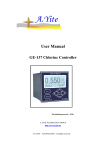
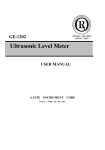
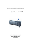
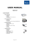
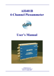
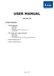
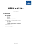
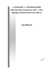
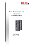
User Manual
GE-134 Dissolved oxygen Controller
The initial password:8008
A.YITE TECHNOLOGY GROUP
http://www.ayite.net
©A.YITE
TECHNOLOGY . All rights reserved.
A.YITE TECHNOLOGY
http://www.ayite.net
CONTENTS
1. Overview……………………………………………………3
2. The structure features………………………………………3
3. Technique features…………………………………………3
4. The function features………………………………………3
5. The installation of meter……………………………………4
5.1 Controller Installation …………………………………4
5.2 The electrode and installation …………………………4
5.3 The electric connection ………………………………5
5.4 Electrical connection …………………………………5
6. Function Keys ……………………………………………5
7. Detailed instructions………………………………………6
7.1 Power-on………………………………………………6
7.2 Main menu ……………………………………………6
7.3 The submenu “parameters” ……………………………6
7.4 Parameter description…………………………………7
7.5 Calibration instructions ………………………………8
8. The submenu “check and set” ……………………………9
8.1 Current output…………………………………………9
8.2 Alarm relay test ………………………………………9
8.3 Change password ……………………………………10
8.4 Input signal test…………………………………………10
8.5 After Service……………………………………………10
9. Daily maintenance…………………………………………10
10. Whole set …………………………………………………11
-2-
A.YITE TECHNOLOGY
http://www.ayite.net
1. Overview
GE-134 dissolved oxygen controller is a microprocessor-line water quality monitor.
Configuration of different dissolved oxygen electrode, the oxygen content of the
aqueous solution for continuous monitoring and control.
2. The structure features
Complete measuring system consists of GE-134 instruments and two parts oxygen
electrode, oxygen electrode contact with the tested solution, aqueous oxygen meter
and temperature display and work state.
3. Technique features
(1)Measuring range:DO:0~~25.00mg/L;
Temperature:-5~60℃;
(2)Basic error:DO:± 0.2mg/LF·S;
Temperature:±0.3℃
(3)The temperature compensation range:0~110℃;
(4)The remain signal of electrode:<1‰;
(5)Response time(90%final): <60seconds(25℃) or <30seconds(35℃)
(6)The stability :<2%F·S every week(normal temperature and normal pressure)
(7)Current output:0~10mA(load resistance<1.5KΩ);
4~20mA(load resistance<750Ω);
(8)Two group of alarm relay:3A 240VAC,6A 28VDC or 120VAC;
(9)power supply:220VAC±10%,50±1Hz,power consumption≤3W;
Or 24VDC,power consumption≤1W;
Or 12VDC,power consumption≤1W;
(10)The dimension:96×96×130mm;
(11)Installation way:panel installation;
The tapping size of electronic unit :91×91mm;
(12)Waterproof Wall Box Size:300(H)*200(W)*167(D)mm;
(13)The electronic unit weight:0.6kg;
( 14 ) Operating conditions : a)Ambient temperature : - 10 ~ 60℃;b)Relative
humidity:no bigger than 90%;c)There are no corrosive gas around; d)There are no
other magnetic fields or electromagnetic fields which produce the negative effect
except the earth magnetic field.
4. The function features
※ Intelligence: the value of single-chip microprocessor to complete measurements of
dissolved oxygen, temperature measurement and compensation;
※ Man-machine dialogue: the menu operation structure, the user can follow the
onscreen prompts action;
※ With multi-parameter display: Simultaneous display of dissolved oxygen values,
temperature and working conditions;
※ Software to set output: 0 ~ 10mA or software selection 4 ~ 20mA output;
-3-
A.YITE TECHNOLOGY
http://www.ayite.net
※ Range and alarm, free to set lower limits; upper and lower limit alarm prompts;
※ Two relay control switch, volume control adjustable hysteresis;
※ Since the password: The user can set or modify the password, so access to the
result of misuse;
Service: To provide technical support and after-sales service contact methods;
※ Optional RS485 / / RS232 communication interface connected to the computer
5. The installation of meter
5.1 The controller shall be installed where it is clean, dry and well-ventilated and
there is no vibration, no corrosive gas or steam. Some space shall be left around the
meter,for the convenience of the operation and overhaul. The meter shall be as close
as possible to the sampling point,for ease of pipe and electric connection. The meter
shall be close to the sensor for the ease of calibration. See the diagram 1 for size:
91mm * 91mm.
91×91mm
Figure 1 hole-tapping size
5.2 Electrode installation diagram
Figure 2
a variety of installation shown in Figure
Sink-or pipeline for high values of dissolved oxygen measurement;
-4-
A.YITE TECHNOLOGY
http://www.ayite.net
5.3 The electric connection
Figure 3 instrument wiring diagram
Wiring instructions:
9、DO measuring electrode terminal
1、High alarm relay normally closed contact
10、DO reference electrode terminal
2、High alarm relay contact common
11、Temperature electrode terminals
3、High alarm relay normally open contact
12、Temperature electrode terminals
4、Low alarm relay normally closed contact
13、Shield terminal
5、Low alarm relay contact common
14、Null
6、Low alarm relay normally open contact
15、DO output current-
7、220VAC or 24VDC+ or 12VDC+
16、DO output current+
8、Zero line or 24VDC- or 12VDC-
17、~24、Null
25、Communication+
26、Communication-
5.4 Electrodes filxed conventional cable length is 5m lead, Terminals Department has
labeled inserts with insert it into the controller back the same number of terminal
symbols can be tightened.
6.
Function Keys
The panel has 6 touch key and they are:Esc 、←、→、↑、↓and Enter .
Esc:shift between the measurement screen and menu screen or return to the
previous menu and status from the menu screen or cancel the input data;
←:move to the first menu item or move the cursor to the left when the data is
input;
→:move to the last menu item or move the cursor to the right when the data is
input;
↑:move the menu upward or numerical value increases;
↓:move the menu downward or numerical value decreases;
Enter:Choose or confirm the menu item and finish the data input or confirm
certain status.
-5-
A.YITE TECHNOLOGY
http://www.ayite.net
7. Detailed instructions
7.1 Power-on:Before the meter is used, check all the pipe connection and the electric
connection. After the power supply is connected, the meter displays as shown in
below left, In over serval seconds, meter will enter into measurement main display.
DO main display
µg/L or mg/L
Automatic switching
6.52
Welcome
µg/L
Normal
status
25.0℃
Temp
Value-based show in which dissolved oxygen, temperature, state of the sub-display.
Status prompt displays the following information: 1. Normal 2 High limit alarm 3 low
limit alarm.
7.2 Main menu: While in the main display status, press ESC key will enter main menu.
It display like below:
Main menu
1.parameters
2.sensor calibrate
3.check and set
4.after service
7.3 The submenu “parameters”:All the parameters under the submenu should be
checked before measuring, otherwise it will run by the preset values. Move the cursor
to the “1.parameters” submenu and press ENTER key, a password will be
requested(preset password is 8008). When enter this submenu, using ↑ or ↓ key move
the cursor, press ENTER key to modify the sub parameters.
-6-
A.YITE TECHNOLOGY
1st
http://www.ayite.net
Disp Type:µg/L
HighAlarm:200.0µg/L
LowAlarm:0.000µg/L
Dead Band:0.010µg/L
CurMethod:4-20mA
Use the following keys one
by one move, or use the left
and right full-screen look.
2st
Out.High:200.0µg/L
Out.Low:0.000µg/L
SensorZero:0.0pA
Sen.Slope:-350pA/mba
Barometric:1013.0mbar
Use the following keys one
by one move, or use the left
and right full-screen look.
3st
Temp.Mode:actual
Man.temp:25.00℃
StationID:1
7.4 Parameter Descriptio:
1)“Disp.Type”: There are there methods: µg(mg)/L、% and mbar. Normal use “µg/L”,
“%” is usually used in bio-fermentation。
2)The “Sensor Zero” and “Sen.Slope”
This two items are used to set the sensor zero point and the sensor slope ratio. The
results of calibration are recorded in here. In addition, this function is also used to
directly modify sensor’s zero point and slope ratio.
3)“Barometic”: This item is used to set atmosphere pressure.
4)The “Alarm High” , “Alarm Low” and “Dead Band”
The “Alarm High” and “Alarm Low” are respectively used to set the high alarm limit
and the low alarm limit. The “Dead Band” is used to set the dead band of alarms.
5)The “Out High” and “Out Low”
The “Out High” and “Out Low” are respectively used to set the output current high
limit and low limit, Out High > Out Low.
6)The “output current(CurMethod)”
This menu is used to setting the meter current output method. Make the selection
between “0-10mA” and “4-20mA”. The relationship between the output current and
the measured dissolved oxygen:
0~10m A output method :I={(D-DL)/(DH-DL)}×10mA;
4~20m A output method :I=4mA+{(D-DL)/(DH-DL)}×16mA。
Among them:I-output current,D-the currently measured dissolved oxygen,DH- the
“output upper limit ” set by users;DL- the “output lower limit ” set by users。
-7-
A.YITE TECHNOLOGY
http://www.ayite.net
7 ) The “temperature intput type(Temp.Mode)” and “manual set
temperature(Man.Temp.)”
The “Temp.Mode” has the “actual measurement temperature (actual)” and “manual
set temperature(manual)”. The “actual measurement temperature” refers to the
temperature actually measured by the temperature sensor ; The “manual set
temperature” refers to the temperature set by the human and it has nothing to do with
the actual solution temperature. This function is mainly used for simulated debugging,
substitute resistance box.
The “Man.Temp.” refers to the temperature which the meter displays when the
“temperature intput type” sets the temperature as “manual set temperature(manual)”.
8)“StationID”: This item is used when communication by RS485, it means the ID
number of the meter in the RS485 network.
7.5 Calibration Description:
Because each oxygen electrode and zero-current slope is different, and with the
consumption of liquid filling, zero current and slope in the course will gradually
change, resulting in aging, and each additional fill fluid or exchange membrane can
also lead to zero current and slope changes, which need regular "calibrated" to ensure
sufficient accuracy. Before entering this menu to enter the correct password, the initial
password is 8008.
The table has a little air of known concentration of calibration and calibration slope
and other methods to choose from.
"Some air calibration slope": the head of oxygen membrane electrode before
calibration should be filled with fill fluid, the installation clean and well maintained
after the electrode head, insert the water samples; and electrode cable connected to the
instrument according to label accurately activated power 1 to 2 hours. Remove the
electrode from the water samples placed vertically in the air, with a clean filter paper
to dry gently drop the head electrode. And then operate the instrument into the "point
slope calibration of the air," below left. Input current to be relatively stable (usually
about 5 minutes) will be automatically calibrated, or manually press the Enter key to
continue, after the right below shows results of calibration reference. At this point
press the Enter key and then press the Escape key, instrument calibration of the
display values should be consistent with or close to Appendix A, see last page. After
completion of calibration measurement can be put in water samples. Only when the
user is put into the air to do a little slope calibration.
Stable until the input current
Result:
Electrode current:-70.00nA
S=-410.0pA./mbar
Temp:25.0℃
Application according to confirm, cancel
Press Enter to save
press the Escape
"Known concentration calibration": about to enter a known concentration after
calibration.
-8-
A.YITE TECHNOLOGY
http://www.ayite.net
8. The submenu “check and set”
8.1“Current output”:
This function is mainly used for the correct checking of output current, and with
this submenu, the user can check the correctness of meter output current within the
full output range. When the meter is connected with the recorder and traditional slave
machine, check whether the recorder and slave machine sampling are correct or not,
so as to detect the fault.
Input the password before entering the submenu. Afterwards one warning will
appear, informing the users that they should guarantee any change in the output
current will not bring any negative effect before they use the meter. Press Enter key to
continue. There will display the present output current on the screen. Press ← → ↑
and ↓ keys to change the output current, Press Enter to stop the changing. Press Enter
again to input the output current what you need.
Notes:When this function is used,the output current is set by the user and it will
change within the full range, guarantee that the adjustable regulator connected on the
output circuit or microcomputer will not produce any negative effect upon the control
output.
Check and Set
Current output
Input signal test
Alarm relay test
Change password
Output current
4.00mA
High alarm:OFF
Low alarm:OFF
use↑↓to change
8.2“Alarm relay test”:Into the book menu display as shown above.This function is
used for testing the alarm relay output.
Load control relay rated current is less than the exposure to current, pressing the left
to connect (power supply not more than 220V);
Load control relay rated current greater than the exposure to current, then the need to
add AC contactor, press the connect at right.
-9-
A.YITE TECHNOLOGY
http://www.ayite.net
8.3“Change password”:After entering this function, input “initial password ”(initial
password is 8008), and then input “new password” complete the modification of user
password.
8.4“Input signal test”: This function is mainly used for simulated debugging by the
meter factory.
8.5“After Service”: This menu shows the after-sales service telephone number,
E-mail and Web address.
9. Daily maintenance
Instruments generally do not need routine maintenance, such as failure to contact
the company, the company's technical staff under the direction of the adjusting.
Dissolved oxygen electrode maintenance, please note the following:
(1)As far as possible into the water sample flow rate constant.
(2)Low dissolved oxygen in the test, the use of hard pipe inlet connection to prevent
air infiltration into the pipe.
(3)Disassembly can not break the electrode film and the misfortune to scratch the
oxygen electrode penetration within the core of the glass bulb head.
(4)Cable connector to keep clean, not damp or water.
(5)Instrument display and the actual measured values varied widely, or low levels of
oxygen can not be measured, it may be filled with liquid oxygen electrode dry, to be
re-poured into the filling liquid. Specific steps are as follows: A. slowly unscrew the
electrode head stainless steel jacket, remove the cylinder-like membranes; B. Discard
the cylinder filling the remaining liquid, and then filled into the first wife of the
oxygen electrode filling solution the inner core, the excess liquid will fill the tank
with the natural discharge of the exhaust electrode (mounted in the cylinder when you
can not leave air bubbles), and then carefully screw on the stainless steel jacket can be.
The power re-activation of more than 1 hour "point slope calibration air" after put into
operation.
(6)When the scene a long time without water when not in use, remove the electrode
should be cleaned, drained membrane filled tuck, put on protective cap, electrode
drying recommended store.
(7)If the electrode damage or failure in need of replacement electrodes, the oxygen
membrane damage in need of replacement.
-10-
A.YITE TECHNOLOGY
http://www.ayite.net
Appendix A
(standard appendix)
saturated oxygen in the water under difference temperature
Temperature Dissolved oxygen Temperature Dissolved oxygen
mg/L
mg/L
℃
℃
0
14.64
20
9.08
1
14.22
21
8.90
2
13.82
22
8.73
3
13.44
23
8.57
4
13.09
24
8.41
5
12.74
25
8.25
6
12.42
26
8.11
7
12.11
27
7.96
8
11.81
28
7.82
9
11.53
29
7.69
10
11.26
30
7.56
11
11.01
31
7.46
12
10.77
32
7.30
10.53
33
7.18
13
10.30
34
7.07
14
10.08
35
6.95
15
9.86
36
6.84
16
9.64
37
6.73
17
9.46
38
6.63
18
9.27
6.53
39
19
Annotation: This table is a reference from JJG291-1999 appendix C。
10.Whole set
Name
Quantity
1)GE-134 DO Controller
2)Oxygen electrode
3)Spare parts
4)Install bracket
5)User manual
1
1
1
2
1
-11-