1
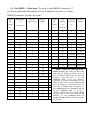
USER’S MANUAL
OF
One To One Continuity Tester
For 16 circuits
Model CT121-16. (version 3_8)
( filename ct121_16_3_8)
BY
FUTURA APSOL PVT. LTD.
1212/B/2, Apte Road,
Shivajinagar,
Pune 411004
020-25531832, 9881138785
E-MAIL : [email protected].
www.futuras.com
INDEX
GENERAL PRECAUTIONS.
1 : INTRODUCTION
1.1 : Function
1.2 : Technical Specifications.
2 : DESCRIPTION OF MENUS :
2.1 : Start Test
2.1.1 : All Circuits
2.1.2 : Circuit by Circuit.
2.2 : Setup:
3 : OPERATION :
3.1 : Front and back panel
3.2 : Display meanings and keys used:
4 : POINTS TO REMEMBER :
5 : ONE TO ONE CONTINUITY CHECKER CONNECTIONS TO RIG
/ FIXTURE / BOARD.
5.1 : I/O connections.
5.2 : Special connections.
GENERAL PRECAUTIONS.
Before using the equipment read the following carefully.
Following points are to be taken care of while using the equipment. These will
protect the equipment from malfunction and any damage.
#
Any external continuity meter like buzzer, bulb or multimeter should be
strictly avoided. Use of these will damage the internal electronic delicate
components.
#
The tester is designed to work for 230V AC with ± 10% of fluctuation. If the
voltage goes below the specified voltage; the tester will not work as expected. It is
advisable to have a voltage stabilizer preferably a CVT.
#
While changing the board; removal and fitting of D type connectors on the
back side of the tester or centronics connector on the board, should be done with
utmost care. These connectors are polarised and hence should not be inserted in
wrong direction. There is a tendency to push the connector hard in the tester
even if polarisation is incorrect. Pushing might damage the connectors on I/O
cards or on the board of the tester.
# The tester has a long life and does not need much of maintenance if used
carefully. The maintenance is required for the rig or mounting board.
#
Check proper earthing at the power supply input of the Cable
Harness Tester.
Warrenty void if equipment is opened by unauthorized person.
1 : INTRODUCTION :
1.1 : Function :
One to One continuity tester is to test one to one continuity of a circuit.
Application can be a fixture with limit switches, a connector or a coupler with open
ends. It does not check midjoints. Tester can test for maximum of 16 circuits/cables.
Last circuit to be tested is user programmable. Set up allows programming of last
circuit. Last circuit can be stored for 25 different harnesses.
It is a microcontroller based tester.
1.2 : Technical Specifications :
Power Supply :
230V ac +/- 10%
One to one continuity tester :
Number of circuits to be tested :
16 circuits i.e. 32 points.
Last circuit to be tested, programmable by user. Refer document for circuit
connections.
Test Voltage :
TTL Logic 1 level @ 5V DC.
Test Current :
In milliamperes.
Tester I/Os :
37 pin D F connectors, 1 nos. terminated at back side of tester.
General
User input :
4 key touch pad sealed, keyboard viz. Enter, Up, Down, Escape.
User output :
16×1 LCD display with backlit.
Buzzer audio output on Pass.
Relay no potential contact rating 230V, 5 A on Pass.
User Interface / functional specifications.
Keys
Enter : Accept command or menu.
Up : Next command in menu or increment number.
Down : Previous command in menu or decrement number.
Escape : escape to previous menu or escape from test.
Menus and submenus : (Menu name and keys accepted)
Start Test? : up / down / Enter.
Setup? : up /down / enter.
Change Component ? : up / down / enter/Escape.
Change cable number
Change data ? : up / down / enter/Escape.
Change last circuit.
Change test mode? : up / down / enter / Escape.
All Circuits : up / down / enter / Escape.
Ckt by ckt : up / down / enter / Escape.
Chng Relay Time? : up / down / enter / Escape.
2 : Description of menus :
2.1 : Start Test :
Starts testing in selected test mode for selected component number.
2.1.1 : All Circuits : Testing of continuity from circuit 1 upto last circuit for the
selected component number. Passed only if ALL CIRCUITS are found correct in one
pass. Finds out and displays, open and short faults. Keeps displaying first fault
located. On every pass, counter is incremented. After passing, displays “Remove
Component” and after removing, displays “Mount Component”. Starts testing, even if
one circuit found connected. After displaying error, any key will not be accepted and
faulty harness will have to be removed. Fault display will be “ Open xx” meaning
open circuit number xx, “short xx yy” meaning shorted circuit numbers xx and yy.
2.1.2 : Ckt by Ckt : Testing of continuity from circuit 1 upto last circuit for the
selected component number. Checks each point and considers correctness of each
point even if continuity is found momentorily. Checking is not done sequentially.
Passes if all points are found correct. Finds out and displays open faults. Keeps
displaying first fault located. On every pass counter is incremented. After passing
displays “Remove Component” and after removing, displays “Mount Component:.
Starts testing even if one circuit found connected. After displaying error, no key will
be accepted and faulty harness will have to be removed. “ Open xx” meaning open
circuit number xx.
Since tester displays “Mount Component” if all circuits are found open, here
care should be taken that at least one fixture should be of locking type and will be
locked throughout testing. Hence Testing will start after mounting component in
this fixture and “Mount Component” display will appear after removing component
from this fixture.
Test mode will end with Escape key.
2.2 : Setup:
In ‘Change Component’ mode, set up facilitates selecting component number out
of 25 nos. Keys ‘up’ and ‘down’ will change component number and ‘enter’ will
accept displayed numbers..
In ‘Change Data’ mode, set up facilitates changing last circuit. Keys ‘up’ and
‘down’ will change last circuit number display and ‘enter’ will accept displayed
numbers.
In ‘Change Test Mode’ mode, setup facilitates selecting test mode from ‘All
Circuits’, ‘Ckt by Ckt’. Keys ‘up’ and ‘down’ will change modes display and ‘enter’
will accept displayed mode.
In ‘Change Relay Time’, allows to set time for which ‘pass’ relay will be ON. It
can be set from minimum 2 seconds to maximum 10 seconds. Up/Dn keys will change
time and Enter key will accept and store. Once set it will be stored in memory and for
any component same relay time will be taken.
3 : Operation :
3.1 : Front and Back panels:
Front Panel : 4 keys keyboard, 16*1 LCD display with backlit.
Back Panel : Mains input socket with fuse (750mA, normal glass) and spare fuse,
Mains power on switch, Relay output terminal strip.
Connect power cord, provided with tester, which is similar to PC mains cord, to
the tester at socket provided on the back panel.
Switch on power using power on switch.
Tester displays “FUTURA VER*****” for @ 2 seconds, last selected test mode
for @3 seconds, last selected component number and its data for @5 seconds and
“START TEST?”.
Use keyboard on front panel for further functions as required. Refer to section 3.2
for display meanings and keys to be used.
Relay : Relay will be normally off and will be on for for set time on Pass. By
default 2 seconds. Relay output is provided on back side on a terminal strip. Pole, NO
and NC are all available for use.
3.2 : Displayed messages, their meanings and keys to be used. :
START TEST? : Start Testing? : ‘Enter’ starts testing, ‘up / down’ next menu,
‘Escape’ no change.
SETUP? : Want to change settings? : ‘Enter’ displays “CHANGE TESTMODE?”,
‘up / down’ next menu, ‘Escape’ to “SETUP?”.
CHANGE COMPONENT ? : Want to change selected component? : ‘Enter’
displays currently selected component and its data. ‘up / down’ next menu, ‘Escape’ to
“SETUP?”
CHANGE DATA ? : Want to change selected component’s data? ( last circuit) :
‘Enter’ displays currently selected component and its data. ‘up / down’ next menu,
‘Escape’ to “SETUP?”
CHANGE TESTMODE? : Want to change test mode? : ‘Enter’ displays existing
test mode, ‘up / down’ next test mode, ‘Escape’ to “SETUP?”.
ALL CIRCUITS? : Select test mode continuity check for all circuits in one pass? :
‘Escape’ to “SETUP?”, ‘up / down’ next / previous menu, ‘Enter’ displays “SET ALL
CIRCUITS”for @ 3 seconds and displays current component number and its database
from memory for @ 3 seconds and then “SETUP?”.
CKT BY CKT? : Select test mode, continuity check circuit by circuit? : ‘Escape’
to “SETUP?”, ‘up / down’ next / previous menu, ‘Enter’ displays “SET CKT BY
CKT”. for @ 3 seconds and displays current component number and its database from
memory for @ 3 seconds and then “SETUP?”
PASS ZZZ : On passing of component in any test mode. ZZZ is counter which
resets on every power on and component change.
MOUNT COMPONENT : In continuity checking, all circuits are open and waiting
for mounting component. ‘Escape’ to TEST?
REMOVE COMPONENT : In continuity checking, tester expects all circuits to be
open. ‘Escape’ to TEST?.
CHNG RELAY TIME : Set pass relay on time from 2 seconds to 10 seconds.
4 : Points to remember :
In circuit by circuit testing mode, connections may not be sequential. Tester will
take care of random circuit numbers making continuity.
In circuit by circuit testing at least one fixture should be of locking type and
will be locked throughout testing. If not then tester will keep displaying “MOUNT
COMPONENT” once it finds all circuits are open.
Counter for all test modes is same and is initialised on every power on and on
entering test mode.
On power on, tester displays “FUTURA” for @ 2 seconds, last selected test mode
for @3 seconds, last selected component number and its data for @5 seconds and
“TEST?”.
On entering test mode displays selected component number and its data for @5
seconds and starts testing.
5.1 : I/O connections : Each Connector 37 pin D type M solder type on rig side.
(On tester, 37 pin D F).
Each 37 pin connector has 16 circuits. “+” indicates one end and “-” indicates
second end.
First connector has circuits 1 to 16. Second has 17 to 32 and so on. Configuration
in all connectors is the same as shown below.
Cable provided has one end as 37 pin D ‘M’ connector and other end as 36 pin
centronics ‘M’. 36 pin ‘F’ connector is mounted on the board. I/O connections are as
below.
I/O No
Pin number on
Pin number on 36
37 pin ‘D’
connector
I/O No
Pin number
Pin number on
pin centronics
on 37 pin
36 pin
connector
‘D’
centronics
connector
+1
1
1
+9
9
-1
20
19
-9
28
+2
2
2
+10
10
-2
21
20
-10
29
+3
3
3
+11
11
-3
22
21
-11
30
+4
4
4
+12
12
-4
23
22
-12
31
+5
5
5
+13
13
-5
24
23
-13
32
+6
6
6
+14
14
-6
25
24
-14
33
+7
7
7
+15
15
-7
26
25
-15
34
+8
8
8
+16
16
-8
27
26
-16
35
Not connected 37 pin D; 17,18,19, 36,37,
Not connected 36 pin centronics; 17,18,35,36.
connector
9
27
10
28
11
29
12
30
13
31
14
32
15
33
16
34
5.2 : For MSSL : Cable from Tester to 18 pole MSSL F connector. 37
pin D type solderable M connector (37 pin F connector on tester) to 18 pole
MSSL F connector (16 poles are used).
37 pin
Pin number
18 pole F
pin no. as
M
on
connector no.
MSSL.
Connec
connector
tor
37 pin
Pin
18 pole F
pin no. as
MSSL.
M
number
connector
Connec
on
no.
tor
connector
1
1
1
1
1
13
2
9
1
20
1
2
1
32
2
10
1
2
1
3
1
14
2
11
1
21
1
4
1
33
2
12
1
3
1
5
1
15
2
13
1
22
1
6
1
34
2
14
1
4
1
7
1
16
2
15
1
23
1
8
1
35
2
16
1
5
1
9
1
17
Not Used
Not Used
1
24
1
10
1
36
Not Used
Not Used
1
6
1
11
1
18
Not Used
Not Used
1
25
1
12
1
37
Not Used
Not Used
1
19
Not Used
Not Used
1
7
1
13
1
26
1
14
1
8
1
15
1
27
1
16
1
9
2
1
1
28
2
2
1
10
2
3
1
29
2
4
1
11
2
5
1
30
2
6
1
12
2
7
1
31
2
8
MSSL : Wiring or connecting of rig /
fixture to tester :All cables provided along
with tester are similar in connections as per
above connection table.To use for I/Os, pin
numbers 1,3,5,7,9,11,13,15 of 18 pole
connector no.1, of 37 pin connector
connected at position CKTs 1-16 on back
panel of tester are one end of circuits 1 to 8
and pin numbers 2,4,6,8,10,12,14,16 are
other end of circuits 1 to 8. Similarly 18
pole connector no.2 are circuits 9 - 16 and
18 pole connector no.1, of 37 pin c
onnector connected at position CKTs 17-32
on back panel of tester are circuits 17- 24.
Similarly 18 pole connector no.2 are
circuits 25 - 48. Similarly remaining circuits
can be used.
Some of Our Products
Cable Harness Tester : PHTM320, PHTM640, PHTM960.
Cable Harness Tester : HTM T32, HTM T64.
One to One Continuity Tester : CT121-16, CT121-32, CT121-48,
CT121-96.
Harness Assembly Aid : HAA64, HAAP64, HAAP96.
Label Data Storage for Printing : LDSP, LDSP-LCD.
Solid State Floppy : SSF.
Gaugelink.
Visit www.futuras.com for details.

![User`s Manual [(ver2_0] Label Data Storage for Printing](http://vs1.manualzilla.com/store/data/005731436_1-9878257490003fe38f3b53735b78440c-150x150.png)
![User`s Manual [(LDSP_LCD_99_2)] Label Data](http://vs1.manualzilla.com/store/data/005846764_1-de86383eb41f3d06a08b51e5958ead91-150x150.png)