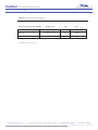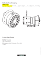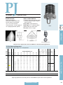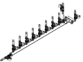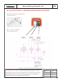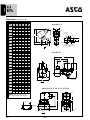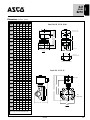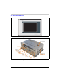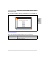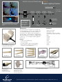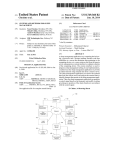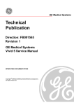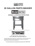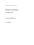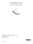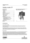
1
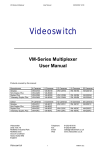
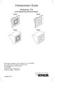
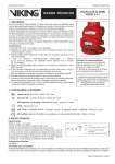
Bradford - Custom Luxury Experience Shower bradfordproducts.com note: tile by others - some features omitted for clarity Bradford Luxury Experience Shower april 2009 Item Description Structural Experience Shower Stainless Steel Specifications Finishes Tile Finish Controls Touch Screen Temperature Sensor Plumbing Hansgrohe Raindance AIR Imperial Showerhead Hansgrohe Body Jets Mister Mist Heads Plumbing Manifold Solenoid Valves Lighting Audio Starscape LED Bullet Lights SoSound Sound Hearts bradford products, llc. 710 sunnyvale drive, wilmington nc 28412 - ph: 800 438 1669 fx: 910 791 0566 file: Bradford_Style_Guide_Doc_032309 Bradford Luxury Experience Shower april 2009 Experience Shower - Overview & Description: A unique variety of multi-temperature water features combined with relaxing chromatherapy lighting, soothing acoustics and rejuvenating aromatherapy creates a delightful experience. A simple to use, yet elegant interface presents the bather with a choice of 5 shower experiences and the owner/operator all the necessary functions to control the system. Networked capabilities allow “online” technical diagnostics and easy downloads of new experiences. Standard Items: • Custom configurations - sizes, shapes, functions • Watertight, structural stainless steel shell • Tile Finish per designer specs • 24” Overhead Rain Imperial Shower Head complete with 5 spray modes • 6 body massagers • Misters overhead • Full color, multi-function touch screen menu • Full color changing, ultra bright LED lightsystem; overhead • Light color and display sequenced in harmony with water and audio features • Tranducer audio speaker system emits sound through the floor and walls of shower • Integral floor drain • Aroma injection system bradford products, llc. 710 sunnyvale drive, wilmington nc 28412 - ph: 800 438 1669 fx: 910 791 0566 file: Bradford_Style_Guide_Doc_032309 Bradford - LEED Information july 2008 bradfordproducts.com page - 1 Leadership in Energy & Environmental Design: ENVIRONMENTALLY SOUND PRODUCTS FOR THE GREEN 21ST CENTURY Bradford Products, LLC, has been a world-leader in the design and fabrication of stainless steel aquatic vessels for the last 25 years. We remain “ahead of the curve” by using and manufacturing environmentally friendly products that are both recycled and recyclable. Bradford has pioneered the use of stainless steel—itself made 65% – 80% from recycled steel—in the manufacture of all manner of aquatic vessels and water features. Bradford’s aquatic vessels not only will out-last comparable aquatic vessels formed of polymerized petrochemicals which employ increasingly scarce and high-cost raw material but are superior to concrete shells as well. Bradford utilizes closed-loop filtration systems that recycle and sanitize water, conserving and reusing that resource. A stainless steel vessel, properly maintained, has a comparatively extended life expectancy which, assuming proper maintenance and care, is far beyond any other material. Recycling and recyclablility is one of the many factors that would permit LEED certification of a project. Stainless steel is recognized as a “green” material and its use, as a feature of the overall design, can be a factor in earning LEED points. bradford products,llc. 710 Sunnyvale Drive, wilmington NC 28412 - 800 438 1669 fx 910 791 0566 Technical Data BLUE SHEET Allegheny Ludlum Corporation u Pittsburgh, PA Stainless Steels Chromium-Nickel Types 302 (S30200), 304 (S30400), 304L (S30403), 305 (S30500) GENERAL PROPERTIES Allegheny Ludlum Types 302 (S30200), 304 (S30400), 304L (S30403), and 305 (S30500) stainless steels are variations of the 18 percent chromium – 8 percent nickel austenitic alloy, the most familiar and most frequently used alloy in the stainless steel family. These alloys may be considered for a wide variety of applications where one or more of the following properties are important: 1. 2. 3. 4. 5. 6. 7. 8. 9. Resistance to corrosion Prevention of product contamination Resistance to oxidation Ease of fabrication Excellent formability Beauty of appearance Ease of cleaning High strength with low weight Good strength and toughness at cryogenic temperatures 10. Ready availability of a wide range of product forms Each alloy represents an excellent combination of corrosion resistance and fabricability. This combination of properties is the reason for the extensive use of these alloys which represent nearly one half of the total U.S. stainless steel production. Type 304 represents the largest volume followed by Type 304L. Types 302 and 305 are used in smaller quantities. The 18-8 stainless steels, principally Types 304 and 304L, are available in a wide range of product forms including sheet, strip, foil and plate from Allegheny Ludlum. The alloys are covered by a variety of specifications and codes relating to, or regulating, construction or use of equipment manufactured from these alloys for specific conditions. Food and beverage, sanitary, cryogenic, and pressure-containing applications are examples. Past users of Type 302 are generally now using Type 304 since AOD technology has made lower carbon levels more easily attainable and economical. There are instances, such as in temper rolled products, when Type 302 is preferred over Type 304 since the higher carbon permits meeting of yield and tensile strength requirements while maintaining a higher level of ductility (elongation) versus that of the lower carbon T304. Type 304L is used for welded products which might be exposed to conditions which could cause intergranular corrosion in service. Type 305 is used for applications requiring a low rate of work hardening during severe cold forming operations such as deep drawing. Other less frequently specified 18-8 stainless steel grades, such as Type 304N (S30451) and Type 304LN (S30453) are also available from Allegheny Ludlum. CHEMICAL COMPOSITION Chemistries per ASTM A240 and ASME SA-240: Element Carbon Manganese Phosphorus Sulfur Silicon Chromium Nickel Nitrogen Percentage by Weight Maximum Unless Range is Specified 302 304 304L 305 0.15 2.00 0.045 0.030 0.75 17.00 19.00 8.00 10.00 0.10 0.08 2.00 0.045 0.030 0.75 18.00 20.00 8.00 10.50 0.10 0.030 2.00 0.045 0.030 0.75 18.00 20.00 8.00 12.00 0.10 0.12 2.00 0.045 0.030 0.75 17.00 19.00 10.50 13.00 -- Data are typical and should not be construed as maximum or minimum values for specification or for final design. Data on any particular piece of material may vary from those shown herein. Stainless Steel Types 302, 304, 304L, 305 Visit our Website at www.alleghenyludlum.com The 18 to 19 percent of chromium which these alloys contain provides resistance to oxidizing environments such as dilute nitric acid, as illustrated by data for Type 304 below. RESISTANCE TO CORROSION General Corrosion The Types 302, 304, 304L and 305 austenitic stainless steels provide useful resistance to corrosion on a wide range of moderately oxidizing to moderately reducing environments. The alloys are used widely in equipment and utensils for processing and handling of food, beverages and dairy products. Heat exchangers, piping, tanks and other process equipment in contact with fresh water also utilize these alloys. Building facades and other architectural and structural applications exposed to non-marine atmospheres also heavily utilize the 18-8 alloys. In addition, a large variety of applications involve household and industrial chemicals. % Nitric Acid Temperature °F (°C) Corrosion Rate Mils/Yr (mm/a) 10 300 (149) 5.0 (0.13) 20 300 (149) 10.1 (0.25) 30 300 (149) 17.0 (0.43) Other laboratory data for Types 304 and 304L in the table below illustrate that these alloys are also resistant to moderately aggressive organic acids such as acetic, and reducing acids such as phosphoric. The 9 to 11 percent of nickel contained by these 18-8 alloys assists in providing resistance to moderately reducing environments. The more highly reducing environments such as boiling dilute hydrochloric and sulfuric acids are shown to be too aggressive for these materials. Boiling 50 percent caustic is likewise too aggressive. General Corrosion in Boiling Chemicals Corrosion Rate, Mils/Yr (mm/a) Boiling Environment Type 304** Type 304L 20% Acetic Acid, Base Metal Welded* 0.1 1.0 (<0.01) (0.03) 0.1 0.1 (<0.01) (<0.01) 45% Formic Acid, Base Metal Welded* 55 52 (1.4) (1.3) 15 19 (0.4) (0.5) 10% Sulfamic Acid, Base Metal Welded* 144 144 (3.7) (3.7) 50 57 (1.3) (1.4) 1% Hydrochloric, Base Metal Welded 98 112 (2.5) (2.8) 85 143 (2.2) (3.6) 20% Phosphoric Acid, Base Metal Welded <1.0 <1.0 (<0.03) (<0.03) 65% Nitric Acid, Base Metal Welded 9.2 9.4 (0.2) (0.2) 8.9 7.4 (0.2) (0.2) 10% Sulfuric Acid, Base Metal Welded 445 494 (11.3) (12.5) 662 879 (16.8) (22.3) 50% Sodium Hydroxide, Base Metal Welded 118 130 (3.0) (3.3) 71 87 (1.8) (2.2) *Autogenous weld on base metal sample. **Types 302 and 305 exhibit similar performance. Data are typical and should not be construed as maximum or minimum values for specification or for final design. Data on any particular piece of material may vary from those shown herein. 2 --- --- Technical Data BLUE SHEET In some cases, the low carbon Type 304L alloy may show a lower corrosion rate than the higher carbon Type 304 alloy. The data for formic acid, sulfamic acid and sodium hydroxide illustrate this. Otherwise, the Types 302, 304, 304L and 305 alloys may be considered to perform equally in most corrosive environments. A notable exception is in environments sufficiently corrosive to cause intergranular corrosion of welds and heat-affected zones on susceptible alloys. The Type 304L alloy is preferred for use in such media in the welded condition since the low carbon level enhances resistance to intergranular corrosion. Stress Corrosion Cracking The Type 302, 304, 304L and 305 alloys are the most susceptible of the austenitic stainless steels to stress corrosion cracking (SCC) in halides because of their relatively low nickel content. Conditions which cause SCC are: (1) presence of halide ions (generally chloride), (2) residual tensile stresses, and (3) temperatures in excess of about 120°F (49°C). Stresses may result from cold deformation of the alloy during forming, or by roller expanding tubes into tubesheets, or by welding operations which produce stresses from the thermal cycles used. Stress levels may be reduced by annealing or stress relieving heat treatments following cold deformation, thereby reducing sensitivity to halide SCC. The low carbon Type 304L material is the better choice for service in the stress relieved condition in environments which might cause intergranular corrosion. Intergranular Corrosion Exposure of the 18-8 austenitic stainless steels to temperatures in the 800°F to 1500°F (427°C to 816°C) range may cause precipitation of chromium carbides in grain boundaries. Such steels are “sensitized” and subject to intergranular corrosion when exposed to aggressive environments. The carbon content of Types 302, 304, and 305 may allow sensitization to occur from thermal conditions experienced by autogenous welds and heat-affected zones of welds. For this reason, the low carbon Type 304L alloy is preferred for applications in which the material is put into service in the as-welded condition. Low carbon content extends the time necessary to precipitate a harmful level of chromium carbides, but does not eliminate the precipitation reaction for material held for long times in the precipitation temperature range. Halide (Chloride) Stress Corrosion Tests Test 302, 304, 304L, 305 Intergranular Corrosion Tests ASTM A 262 Evaluation Test Practice B Base Metal Welded Practice E Base Metal Welded Practice A Base Metal Welded U-Bend (Highly Stressed) Samples 42% Magnesium Base Metal Chloride, Boiling Welded 33% Lithium Base Metal Chloride, Boiling Welded 26% Sodium Base Metal Chloride, Boiling Welded 40% Calcium Base Metal Cracked, 144 Hours -- Base Metal No Cracking Welded No Cracking Corrosion Rate, Mils/Yr (mm/a) 302, 304, 305 304L 20 (0.5) Intergranular 23 (0.6) Corrosion 20 (0.5) 20 (0.5) No Fissures on Bend Some Fissures on Weld (unacceptable) No Fissures No Fissures Step Structure Ditched (unacceptable) Step Structure Step Structure Chloride, Boiling Ambient Temperature Seacoast Exposure Cracked, 1 to 20 hours Cracked, ½ to 21 hours Cracked, 24 to 96 hours Cracked, 18 to 90 hours Cracked, 142 to 1004 hours Cracked, 300 to 500 hours Data are typical and should not be construed as maximum or minimum values for specification or for final design. Data on any particular piece of material may vary from those shown herein. 3 Stainless Steel Types 302, 304, 304L, 305 Visit our Website at www.alleghenyludlum.com Thermal Conductivity: The above data illustrate that various hot chloride solutions may cause failure after differing lengths of time. The important thing to note is that failure eventually occurs under these conditions of chloride presence, high stresses and elevated temperatures. Temperature Range Pitting/Crevice Corrosion The 18-8 alloys have been used very successfully in fresh waters containing low levels of chloride ion. Although Type 304 tubing has been used in power plant surface condenser cooling water with as much as 1000 ppm chloride, this performance can only result from careful cleaning of the tubes during use and care to avoid stagnant waters from remaining in contact with the tube. Generally, 100 ppm chloride is considered to be the limit for the 18-8 alloys, particularly if crevices are present. Higher levels of chloride might cause crevice corrosion and pitting. For the more severe conditions of higher chloride levels, lower pH and/or higher temperatures, alloys with higher molybdenum content such as Type 316 or AL-6XN® alloy should be considered. Interestingly, Types 304 and 304L stainless steels pass the 100 hour, 5 percent neutral salt spray test (ASTM B117) with no rusting or staining of samples. However, Type 304 building exteriors exposed to salt mists from the ocean are prone to pitting and crevice corrosion accompanied by severe discoloration. The 18-8 alloys are not recommended for exposure to marine environments. Modulus of Elasticity in Tension: 29 x 106 psi (200 GPa) Linear Coefficient of Thermal Expansion: Coefficients cm/cm/°C 68 - 212 68 - 1600 20 - 100 20 - 870 9.2 x 10⁻⁶ 11.0 x 10⁻⁶ 16.6 x 10⁻⁶ 19.8 x 10⁻⁶ 9.4 12.4 16.3 21.4 °F °C Btu/lb/°F 32 - 212 0 - 100 0.12 J/kg·K 500 The 18-8 alloys are generally non-magnetic in the annealed condition with magnetic permeability values typically less than 1.02 at 200H. As illustrated below, permeability values will vary with composition and will increase with cold work. Type 305 with the highest nickel content is the most stable of these austenitic alloys and will have the lowest permeability when cold worked. The following data are illustrative: 0.285 lb/in3 (7.90 g/cm3) in/in/°F 100 500 W/m·K Magnetic Permeability Density: °C 212 932 Btu/hr·ft·°F Specific Heat: PHYSICAL PROPERTIES °F °C The overall heat transfer coefficient of metals is determined by factors in addition to the thermal conductivity of the metal. The ability of the 18-8 stainless grades to maintain clean surfaces often allows better heat transfer than other metals having higher thermal conductivity. Consult the Allegheny Ludlum Technical Center (724-226-6300) for further information. The reader is invited to consult the Allegheny Ludlum Technical Center with questions concerning the suitability of the 18-8 alloys for specific environments. Temperature Range °F Data are typical and should not be construed as maximum or minimum values for specification or for final design. Data on any particular piece of material may vary from those shown herein. ®Registered Trademark of Allegheny Ludlum Corporation 4 Magnetic Permeability Percent Cold Work 302 304 304L 305 0 10 30 50 1.004 1.039 1.414 3.214 1.005 1.009 1.163 2.291 1.015 1.064 3.235 8.480 1.002 1.003 1.004 1.008 Technical Data BLUE SHEET Melting Range Electrical Resistivity °F °C 2,550 - 2,590 1,399 - 1,421 Temperature °C °F 68 212 392 752 1112 1472 1652 MECHANICAL PROPERTIES 20 100 200 400 600 800 900 Microhm-in Microhm-cm 28.3 30.7 33.8 39.4 43.7 47.6 49.6 72 78 86 100 111 121 126 Room Temperature Mechanical Properties Minimum mechanical properties for annealed Types 302, 304, 304L and 305 austenitic stainless steel plate, sheet and strip as required by ASTM specifications A 240 and ASME specification SA-240 are shown below. Minimum Mechanical Properties Required by ASTM A 240, and ASME SA-240 Property 302, 304 304L 305 0.2% Offset Yield Strength, psi MPa 30,000 205 25,000 170 30,000 205 Ultimate Tensile Strength, psi MPa 75,000 515 70,000 485 75,000 515 Percent Elongation in 2 in. or 51 mm 40.0 40.0 40.0 Hardness, Max., Brinell RB 201 92 201 92 183 88 Data are typical and should not be construed as maximum or minimum values for specification or for final design. Data on any particular piece of material may vary from those shown herein. 5 Stainless Steel Types 302, 304, 304L, 305 Visit our Website at www.alleghenyludlum.com Effect of Cold Work Low and Elevated Temperature Properties Deformation of the 18-8 alloys at room or slightly elevated temperatures produces an increase in strength accompanied by a decrease in elongation value. A portion of this increase in strength is caused by partial transformation of austenite to martensite during deformation. As shown by the permeability data, the Type 302, 304 and 304L alloys are more prone to martensite formation than the Type 305 alloy. Strengthening during deformation is, therefore, more pronounced in the leaner compositions. Among the 18-8 alloys, Type 305 alloy with highest nickel content exhibits the least amount of work hardening. Typical data are shown below. Typical short time tensile property data for low and elevated temperatures are shown below. At temperatures of 1000°F (538°C) or higher, creep and stress rupture become considerations. Typical creep and stress rupture data are also shown below. Test Temperature 6 Tensile Strength Elongation (MPa) psi (MPa) Percent in 2" or 51 mm -423 -253 100,000 690 250,000 1725 25 -320 -196 485 230,000 1585 35 °F Data are typical and should not be construed as maximum or minimum values for specification or for final design. Data on any particular piece of material may vary from those shown herein. 0.2% Yield Strength °C psi 70,000 -100 -79 50,000 345 150,000 1035 50 70 21 35,000 240 90,000 620 60 400 205 23,000 160 70,000 485 50 800 427 19,000 130 66,000 455 43 1200 650 15,500 105 48,000 330 34 1500 815 13,000 90 23,000 160 46 Technical Data BLUE SHEET typically about 35 percent of the tensile strength. Substantial variability in service results is experienced since additional variables influence fatigue strength. As examples – increased smoothness of surface improves strength, increased corrosivity of service environment decreases strength. WELDING The austenitic stainless steels are considered to be the most weldable of the high-alloy steels and can be welded by all fusion and resistance welding processes. The Types 302, 304, 304L and 305 alloys are typical of the austenitic stainless steels. Two important considerations in producing weld joints in the austenitic stainless steels are: 1) preservation of corrosion resistance, and 2) avoidance of cracking. A temperature gradient is produced in the material being welded which ranges from above the melting temperature in the molten pool to ambient temperature at some distance from the weld. The higher the carbon level of the material being welded, the greater the likelihood that the welding thermal cycle will result in the chromium carbide precipitation which is detrimental to corrosion resistance. To provide material at the best level of corrosion resistance, low carbon material (Type 304L) should be used for material put in service in the welded condition. Alternately, full annealing dissolves the chromium carbide and restores a high level of corrosion resistance to the standard carbon content materials. Impact Resistance The annealed austenitic stainless steels maintain high impact resistance even at cryogenic temperatures, a property which, in combination with their low temperature strength and fabricability, has led to their use in handling liquified natural gas and other cryogenic environments. Typical Charpy V-notch impact data are shown below. Temperature °F °C Weld metal with a fully austenitic structure is more susceptible to cracking during the welding operation. For this reason, Types 302, 304, and 304L alloys are designed to resolidify with a small amount of ferrite to minimize cracking susceptibility. Type 305, however, contains virtually no ferrite on solidification and is more sensitive to hot cracking upon welding than the other alloys. Charpy V-Notch Energy Absorbed Foot - pounds Joules 75 23 150 200 -320 -196 85 115 -425 -254 85 115 If filler metal is required, Type 308 (20% Cr-11% Ni) is generally used. This enriched composition avoids martensite which might otherwise form in multipass welds. Chemistry is controlled to allow a small amount of ferrite in the deposit to limit hot cracking tendency. Fatigue Strength The fatigue strength or endurance limit is the maximum stress below which material is unlikely to fail in 10 million cycles in air environment. The fatigue strength for austenitic stainless steels, as a group, is Data are typical and should not be construed as maximum or minimum values for specification or for final design. Data on any particular piece of material may vary from those shown herein. 7 Stainless Steel Types 302, 304, 304L, 305 Visit our Website at www.alleghenyludlum.com Many of the uses of stainless steel involve cleaning or sterilizing on a regular basis. Equipment is cleaned with specially designed caustic soda, organic solvent or acid solutions such as phosphoric or sulfamic acid (strongly reducing acids such as hydrofluoric or hydrochloric may be harmful to these stainless steels). Type 309 (23% Cr – 13.5% Ni) or nickel-base filler metals are used in joining the 18-8 austenitic alloys to carbon steel. HEAT TREATMENT The austenitic stainless steels are heat treated to remove the effects of cold forming or to dissolve precipitated chromium carbides. The surest heat treatment to accomplish both requirements is the solution anneal which is conducted in the 1850°F to 2050°F range (1010°C to 1121°C). Cooling from the anneal temperature should be at sufficiently high rates through 1500-800°F (816°C – 427°C) to avoid reprecipitation of chromium carbides. Cleaning solutions need to be drained and stainless steel surfaces rinsed thoroughly with fresh water. Design can aid cleanability. Equipment with rounded corners, fillets and absence of crevices facilitates cleaning as do smooth ground welds and polished surfaces. SURFACE FINISHES These materials cannot be hardened by heat treatment. A range of surface finishes is available. These are designated by a series of numbers. CLEANING Despite their corrosion resistance, stainless steels need care in fabrication and use to maintain their surface appearance even under normal conditions of service. Number 1 Finish – is hot rolled annealed and descaled. It is available in plate and sheet and is used for functional applications where a smooth decorative finish is not important. In welding, inert gas processes are used. Scale or slag that forms from welding processes is removed with a stainless steel wire brush. Normal carbon steel wire brushes will leave carbon steel particles in the surface which will eventually produce surface rusting. For more severe applications, welded areas should be treated with a descaling solution such as a mixture of nitric and hydrofluoric acids and these should be subsequently washed off. Number 2D Finish – is a dull finish produced by cold rolling, annealing and descaling. This finish is favorable for the retention of lubricants in drawing or forming operations and is preferred for deep drawn and formed parts. Number 2B Finish – is a brighter finish than 2D. It is produced much like the 2D finish except that the final cold rolling is done with smooth polished rolls. This is a general purpose finish used for all but severe cold forming. Because it is smoother as produced, it is more readily polished than 1 or 2D finishes. For material exposed in inland, light industrial or milder service, minimum maintenance is required. Only sheltered areas need occasional washing with a stream of pressurized water. In heavy industrial areas, frequent washing is advisable to remove dirt deposits which might eventually cause corrosion and impair the surface appearance of the stainless steel. Number 2BA Finish – is a very smooth finish produced by cold rolling and bright annealing. A light pass using highly polished rolls produces a glossy finish. A 2BA finish may be used for lightly formed applications where a glossy finish is desired in the as formed part. Stubborn spots and deposits like burned-on food can be removed by scrubbing with a nonabrasive cleaner and fiber brush, a sponge or pad of stainless steel wool. The stainless steel wool will leave a permanent mark on smooth stainless steel surfaces. Polished finishes – a variety of ground finishes is available. Data are typical and should not be construed as maximum or minimum values for specification or for final design. Data on any particular piece of material may vary from those shown herein. 8 Technical Data BLUE SHEET Because special equipment or processes are used to develop these finishes, not all finishes are available in the range of products produced by Allegheny Ludlum. Surface finish requirements should be discussed with Allegheny Ludlum mill representatives. All of the grades are accepted for use in food preparation and storage by the National Sanitation Foundation and for contact with dairy products by the Dairy and Food Industries Supply Association – Sanitary Standards Committee and are standard materials used in each industry. Similarly, Types 304 and 304L are standard materials of construction in the brewery industry. SPECIFICATION COVERAGE Because of the extensive use of these austenitic stainless steels, and their broad specification coverage, the following list of specifications is representative, but not complete. Product Form Plate, Sheet and Strip Specification ASTM A 240 ASME SA-240 A 249/A 249M SA-249/SA-249M (304, 304L, 305 (304, 304L only) Seamless and/or Welded only), A 269/ A269M (304, Tubing 304L only), A554 A 312/A 312M, SA-312/SA-312M, Seamless A 409/A 409M SA-409/SA-409M and/or Welded (304, 304L only) (304, 304L only) Pipe Bar, Wire A 276, A 478, A SA-479/SA-479M 479/A 479M (302, 304, 304L (302, 304, 304L only) only) Billet, Forgings A 314, A 473 Flanges, Fittings A 182/A 182M, A 403/A 403M (304, 304L only) SA-182/SA-182M, SA-403/SA-403M (304, 304L only) In Section II, Part D of the ASME Boiler and Pressure Vessel Code, Type 304 is assigned allowable stresses for a variety of product forms to maximum use temperatures of 1500°F (816°C). Type 304L coverage includes fewer product forms with lower allowable stresses to maximum use temperature of 800°F (426°C) while Types 302 and 305 have very limited coverage. Data are typical and should not be construed as maximum or minimum values for specification or for final design. Data on any particular piece of material may vary from those shown herein. 9 Bradford - Custom Luxury Experience Shower april 2008 bradfordproducts.com page - 1 Controls - Touchscreen: A simple to use, yet elegant interface presents the bather with a choice of 5 shower experiences and the owner/operator with all the functions necessary to control the overall system. Networked capabilities allow “online” technical diagnostics and easy downloads of new experiences. bradford products,llc. 710 Sunnyvale Drive, wilmington NC 28412 - 800 438 1669 fx 910 791 0566 Bradford - Custom Luxury Experience Shower april 2008 bradfordproducts.com page - 1 Controls - Touchscreen functions: Arctic Mist Body Spray Tropical Rain Island Storm Full Experience bradford products,llc. 710 Sunnyvale Drive, wilmington NC 28412 - 800 438 1669 fx 910 791 0566 Bradford - Custom Luxury Experience Shower april 2008 bradfordproducts.com page - 1 Controls - Temperature Sensor: Resistance temperature detectors (RTD) accurately sense temperature with an excellent degree of repeatability and interchangeability of elements. The RTD is composed of certain metallic elements whose change in resistance is a function of temperature. In operation, a small excitation current is passed across the element, and the voltage, which is proportional to resistance, is then measured and converted to units of temperature calibration. The RTD element is manufactured by winding a wire (wire wound elements) or plating a film (thin film elements) on a ceramic or glass core and sealing the element within a ceramic or glass capsule. Since most RTDs have a low initial resistance, often 100 ohms, and have a small change in resistance per unit of temperature range, the resistance of the lead wire is often compensated for with a three or four wire bridge configuration built into the measuring devices. By selecting the proper elements and protective sheathing, RTDs can operate in a temperature range of (-200 to 650) °C [-328 to 1202] °F. Specific Sensor: 0.25-inch diameter x 4-inch long, with 0.5-inch NPT compression fitting, 100 ohm, 3-wire, with 36-inch leads and plug/jack. bradford products,llc. 710 Sunnyvale Drive, wilmington NC 28412 - 800 438 1669 fx 910 791 0566 Bradford Luxury Experience Shower april 2009 Plumbing - Requirements / Flow Rates Plumbing Requirements DETAIL GPM per unit Qty. Total 24” Raindance Imperial 7.5 gpm MAX 1 7.5 gpm Body Jets less than 1 gpm 6 6 gpm Misters 0.5 gpm 2 1 gpm *with 40 psi water pressure. bradford products, llc. 710 sunnyvale drive, wilmington nc 28412 - ph: 800 438 1669 fx: 910 791 0566 file: Bradford_Style_Guide_Doc_032309 Raindance Imperial 600 AIR Showerhead 28403001 Product Features • 24” Spray face • Ceiling flush mount • RubitTM cleaning system • 358 no-clog spray channels • Three spray modes: 12” rain, dual rain, triple massage • 2.5 gpm per spray mode Code Compliance This unit meets or exceeds the following: • ASME A112.18.1 • CSA B125.1 • Listed by IAPMO • Approved for use in Massachusetts Available Finishes Chrome 28403001 Required Accessories Rainidance Imperial basic set 28412181 Ecostat/EcoMax rough 15374181 Volume control rough 13975181 Quattro diverter rough 13932181 Trim kits for all three roughs -- many Axor styles available The measurements shown are for reference only. Products and specifications shown are subject to change without notice. Specification sheet revised 1/2008 Raindance Imperial Basic Set 28412181 Product Features • Required for Raindance Imperial • Three flexible hose connections 1/2” NPT male inlets Code Compliance This unit meets or exceeds the following: • ASME A112.18.1 • CSA B125.1 • Listed by IAPMO • Approved for use in Massachusetts Required Accessories Raindance Imperial 600 AIR showerhead 28403001 Ecostat / EcoMax rough 15374181 Volume control rough 13975181 Quattro diverter rough 13932181 Trim kits for all three roughs -- many Axor styles available The measurements shown are for reference only. Products and specifications shown are subject to change without notice. Specification sheet revised 1/2008 Bodyvette Stop Bodyspray 28467XX1 Available in Chrome (00), Oil Rub Bronze (62), Steel (80), Brushed Nickel (82), Polished NIckel (83), Polished Brass (93) Product Specification US - Specification Sheet • Revised 02/2007 RubitTM cleaning system Adjustable spray angle 1/2” female NPT inlet Built-in temporary shutoff -- shuts water off to a trickle 1.6 gpm PJ Smallest Physical Size DESIGN FEATURES • High energy efficiency • One-piece, compact construction • No whirl vanes or internal parts • 1/8” or 1/4” male connection • 100-mesh screen, 10 micron paper filter or polypropylene filter optional SPRAY CHARACTERISTICS • Finest fog of any direct pressure nozzle • Produces high percentage of droplets under 50 microns Spray pattern: Cone-shaped Fog Spray angle: 90°. For best 90° pattern operate nozzle at or above 60 psi Flow rates: 0.013 to 1.4 gpm Metal MISTING Male Fog Fog Pattern PJ with polypropylene filter Dimensions are approximate. Check with BETE for critical dimension applications. PJ Flow Rates and Dimensions Impingement, 90° Spray Angle, 1/8" or 1/4" Pipe Sizes Approx. Male Pipe Nozzle K Size Number Factor 1/4 40 PSI Spray Orifice (inches) Approx. Wt. 50 PSI 60 PSI 80 PSI 100 PSI 200 PSI 400 PSI Height Pipe Dim. (in.) (oz.) Dia. (in.) D H (in.) Size A B Metal 1/8 0.75 0.44 PJ6 0.00095 0.006 0.007 0.008 0.010 0.013 0.019 0.006 10 5 PJ8 0.00180 0.013 0.014 0.016 0.018 0.025 0.036 0.008 10 5 PJ10 0.00269 0.017 0.019 0.021 0.024 0.027 0.038 0.054 0.010 10 5 PJ12 0.00364 0.023 0.026 0.028 0.033 0.036 0.051 0.073 0.012 10 5 PJ15 0.00585 0.032 0.037 0.041 0.045 0.052 0.059 0.083 0.117 0.015 10 5 PJ20 0.0106 0.058 0.067 0.075 0.082 0.095 0.11 0.15 0.21 0.020 12 6 PJ24 0.0158 0.087 0.10 0.11 0.12 0.14 0.16 0.22 0.32 0.024 16 8 PJ28 0.0206 0.11 0.13 0.15 0.16 0.18 0.21 0.29 0.41 0.028 18 9 PJ32 0.0285 0.16 0.18 0.20 0.22 0.25 0.28 0.40 0.57 0.032 22 11 PJ40 0.0443 0.24 0.28 0.31 0.34 0.40 0.44 0.63 0.89 0.040 24 12 0.25 1/4 0.97 Flow Rate (GPM) = K √ ⎯⎯⎯ PSI ⎯ Standard Materials: Brass, 303 Stainless Steel and 316 Stainless Steel. Spray angle performance varies with pressure. Contact BETE for specific data on critical applications. www.BETE.com 0.56 CALL 413-772-0846 OR 30 PSI Approx. Approx. Coverage Call for the name of your nearest BETE representative. 1/8 GALLONS PER MINUTE @ PSI 65 Bradford - Audio System bradfordproducts.com oct 2008 page - 1 Audio - So SoundHearts: SO SoundHearts - Transducers with non-magnetic bolt with 2 pole transducer connector. Mounted externally on stainless steel shell vessel. Hard wire into facility audio system by others. NOTE: Stainless steel plate shown to represent vessel structure or external surface only. bradford products,llc. 710 Sunnyvale Drive, wilmington NC 28412 - 800 438 1669 fx 910 791 0566 Electric Actuated Ball Valve 2-way Brass Body 1/4” to 4” NPT SERIES 5600 5601 Features Direct mount ISO5211 full port brass ball valve Highly visible LED light gives continuous status indication Industrial IP65 weatherproof actuator, UV protected Multi-voltage capable with auto-voltage sensing Electronic torque limiter - protects against valve jams Anti-condensation heater Manual override with visual valve position indicator Electrical connections via external DIN plugs, no need to remove the cover Two dry contact auxiliary limit switches used to confirm valve open/closed position Operation Applications On-off control of water, air, oil and other media compatible with the materials of construction. Steam service up to 25 PSI with optional high temperature mounting bracket. Suitable for vacuum service up to 29”Hg. Actuator designed for 75% duty cycle. Electric actuated valve uses power-to-open and power-to-close, stays in the last known position with power failure. On receipt of a continuous voltage signal, the motor runs and via a flat gear system rotates the ball 90º. The motor is automatically stopped by internal cams striking limit switches. On receipt of a reversing continuous signal, the motor turns in the opposite direction reversing the valve position. Description Temperature Range Valve Body Brass Ball Chrome plated brass Ball Seats Teflon with energized Viton O-ring backing Full port 2-piece brass ball valve is designed for unrestricted flow and low pressure drop. Teflon ball seats are energized with O-rings for low torque and extended life. Unique leak free stem seal design incorporates double Orings and two Teflon auxiliary seals for the perfect stem seal design (negating the need for stem seal adjustment common to conventional style ball valves). These valves enjoy the reputation of having the highest performance and lowest operating torque in the industry. Lower operating torque equates to the use of a smaller size actuator, which in turn leads to a smaller profile and a less expensive package. Stem Seals Teflon and double Viton O-rings Optional Functions Actuator Enclosure Anti-corrosive Polyamide Position Indicator Glass filled Polyamide Fasteners Stainless Steel Failsafe BSR - Battery Spring Return Kit - actuator fails to a safe position with loss of power Modulating DPS - Digital Positioning System - valve position controlled by 4-20mA or 010V control signal Working Temperature: 0 to 158º F (-18 to 70º C) Media temperatures up to 266º F (130º C) with optional high temp. mounting bracket Ball Valve Temperature Rating: 0 to 366º F (-18 to186º C) maximum Actuator Temperature Rating: -4 to +158º F (-20 to 70º C) maximum Construction Doc: 5600.5601.0510 Cornelius, N.C. • USA www.valworx.com 1 SERIES 5600 5601 Specifications (English units) Stock Number Pipe Size (NPT) Orifice Size (inch) Cv Flow Factor Pressure Max.(PSI)* Cycle Time/90º (seconds) Max. Current Draw (Amps) 115VAC 240VAC 24VAC 12VDC 24VDC HIGH VOLTAGE: 85-240v AC or DC 560002 1/4 0.39 6 600 11 0.17 0.09 - - - 560003 3/8 0.39 7 600 11 0.17 0.09 - - - 560004 1/2 0.56 19 600 11 0.17 0.09 - - - 560006 3/4 0.75 34 600 11 0.17 0.09 - - - 560008 1 1.00 50 600 11 0.17 0.09 - - - 560010 1-1/4 1.18 103 600 11 0.17 0.09 - - - 560012 1-1/2 1.50 267 600 11 0.17 0.09 - - - 560016 2 2.00 307 600 11 0.17 0.09 - - - 560020 2-1/2 2.50 626 600 14 0.24 0.11 - - - 560024 3 3.00 1012 300 14 0.24 0.11 - - - 560032 4 3.74 1612 150 30 0.22 0.09 - - - LOW VOLTAGE: 12-24v AC or DC 560102 1/4 0.39 6 600 12 - - 0.085 2.05 1.00 560103 3/8 0.39 7 600 12 - - 0.085 2.05 1.00 560104 1/2 0.56 19 600 12 - - 0.085 2.05 1.00 560106 3/4 0.75 34 600 12 - - 0.085 2.05 1.00 560108 1 1.00 50 600 12 - - 0.085 2.05 1.00 560110 1-1/4 1.18 103 600 12 - - 0.085 2.05 1.00 560112 1-1/2 1.50 267 600 12 - - 0.085 2.05 1.00 560116 2 2.00 307 600 12 - - 0.085 2.05 1.00 560120 2-1/2 2.50 626 600 16 - - 1.20 3.08 1.40 560124 3 3.00 1012 300 16 - - 1.20 3.08 1.40 560132 4 3.74 1612 150 35 - - 0.90 2.10 1.20 Cv is the GPM of water at 60º F that will pass through the valve with 1 PSI pressure drop * Pressure @ 158º F (pressure reduced on 1/4” thru 2-1/2” sizes to 550 PSI @ 200º F, 400 PSI @ 266º F) Doc: 5600.5601.0510 Cornelius, N.C. • USA www.valworx.com 2 SERIES 5600 5601 Electrical Wiring for On/Off and Failsafe BSR Versions Voltage: 85-240V AC or DC, 12-24V AC or DC Auto-voltage sensing FUNCTION: ON-OFF VERSION FUNCTION: ON-OFF with FAILSAFE BSR OPTION Power Connection Wiring is the same as standard ON-OFF version. Power to PIN 1(N/-) and PIN 2 (H/+) closes the valve. Power open, power close - trickle charges battery system in either open or closed position. Power to PIN 1(N/-) and PIN 3 (H/+) opens the valve. Actuator sent by battery power to pre-set failsafe position with power failure. Stays in last known position with loss of power. Actuator returns to pre-failure position on power resumption. Doc: 5600.5601.0510 Factory preset to fail normally closed (optional normally open position). Cornelius, N.C. • USA Wiring I.D. for Optional Prewired DIN Plug Cables PIN 1 Black PIN 2 White PIN 3 Red GRD (E) Green www.valworx.com 4 SERIES 5600 5601 Electrical Wiring for Modulating DPS Versions Voltage: 85-240V AC or DC, 12-24V AC or DC Control Signal: 4-20mA or 0-10V Auto-voltage sensing FUNCTION: MODULATING DPS VERSION Power open, power close - actuator movement controlled by input signal 4-20mA or 0-10VDC. Wiring I.D. for Optional Prewired DIN Plug Cables Standard operation: 4mA or 0V = actuator closed, 20mA or 10V = actuator open (can be reversed). PIN 1 Black PIN 2 White PIN 3 Red GRD (E) Green Actuator closes with loss of control signal, stays in last known position with loss of main power. Output signal (in same format as supply signal) provided as standard. Doc: 5600.5601.0510 Cornelius, N.C. • USA www.valworx.com 5 SERIES 5600 5601 Dimensions: inches (mm) Dimensions remain unchanged for all versions (on-off, failsafe & modulating) NPT A B C F H W Weight lbs (kg) 1/4” 7.00 (178) 5.87 (149) 1.28 (32.5) 2.64 (67) 7.15 (182) 4.33 (110) 4.9 (2.3) 3/8” 7.00 (178) 5.87 (149) 1.28 (32.5) 2.64 (67) 7.15 (182) 4.33 (110) 4.8 (2.2) 1/2” 7.00 (178) 5.87 (149) 1.28 (32.5) 2.64 (67) 7.15 (182) 4.33 (110) 4.8 (2.2) 3/4” 7.00 (178) 5.87 (149) 1.36 (34.5) 3.00 (76) 7.23 (184) 4.33 (110) 5.0 (2.7) 1” 7.00 (178) 5.87 (149) 1.79 (45.5) 3.35 (85) 7.66 (195) 4.33 (110) 5.7 (2.6) 1-1/4” 7.00 (178) 5.87 (149) 1.93 (49) 3.66 (93) 7.80 (198) 4.33 (110) 6.3 (2.9) 1-1/2” 7.00 (178) 5.87 (149) 2.52 (64) 4.13 (105) 8.39 (213) 4.33 (110) 7.8 (3.5) 2” 7.00 (178) 5.87 (149) 2.88 (73.2) 4.80 (122) 8.75 (222) 4.33 (110) 9.4 (4.3) 2-1/2” 7.00 (178) 7.72 (197) 3.48 (88.4) 6.10 (155) 11.20 (285) 4.33 (110) 14.2 (6.5) 3” 7.00 (178) 7.72 (197) 3.85 (97.8) 6.89 (175) 11.60 (295) 4.33 (110) 18.7 (8.5) 4” 7.00 (178) 7.72 (197) 4.59 (117) 8.03 (204) 12.30 (312) 4.33 (110) 28.5 (13) Doc: 5600.5601.0510 Cornelius, N.C. • USA www.valworx.com 6 Doc: j3.dps.0209 Modulating DPS “Digital Positioning System” for J3 Electric Actuators Series J3-DSP Modulating DPS (Digital Positioning System) Digital control ensures highly sensitive and repeatable control, with all the usual positioner characteristics coming in at under 1% (actuator only - including hysteresis, linearity & precision). Overall accuracy of valve assembly will vary depending on the type of valve used and method of mounting the valve. The DPS is self calibrating, and on initial start-up or on restoration following a power cut, will go through a short automatic set-up sequence. Standard features include: DSP kit is retro-fittable to the standard J3 onoff actuator In situations where the actuator is used in manual mode (eg: commissioning) and put back into automatic mode with the actuator out of it’s normal operating quadrant, the DPS will auto-adjust itself back into the correct quadrant, re-set itself, and be ready for use. Self-calibrating Provides a proportional output signal DSP virtually eliminates ‘hunting’ Economically priced. The DPS modulating kit is pre-installed at the factory when ordered as an option with a J3 actuator or J3 electric actuated valve assembly. The DPS system provides accurate modulating function whereby the movement of the actuator is controlled by either a 4-20mA or a 0-10VDC control signal. Any change in the control input signal results in a corresponding and proportional change in the position of the actuator. Nominal impedance: 4-20mA signal 100 ohms; 0-10v signal 10K ohms The DPS can be supplied as a retro-fit kit containing all the parts required to convert a standard on-off actuator to a modulating unit, and can be used in conjunction with the battery spring return BSR kit to produce failsafe modulating functionality. This is achieved with the use of an unique internal digital positioning system. An internal microprocessor on the DPS circuit board continuously monitors digitally the analogue input and output signals and compares them to the physical position via an output shaft feedback system, moving the actuator as required to balance the signals. 1 J3 Electrical Wiring: Model 20 - 85 AC (1ph) OR DC SUPPLY - WIRING FOR MODULATING ACTUATORS All electrical connections are made by external DIN plugs ( n o need to remove cover ) : Parts ( 1 ) through ( 7 ) supplied with the kit. Three DIN plugs included. FUNCTION: MODULATING VERSION Wiring for Pre-wired DIN Cables Power open, power close - actuator movement controlled by input signal (4-20mA or 0-10VDC) PIN 1 Black Standard operation: 4mA or 0V = actuator closed, 20mA or 10V = actuator open (can be reversed) PIN 2 White Standard operation: Actuator closes on loss of control signal, stays put on loss of mains power PIN 3 Red GRD (E) Green Output signal (in same format as supply signal) provided as standard. 2 4 2/2 General Service Solenoid Valves SERIES Brass or Stainless Steel Bodies 3/8" to 2 1/2" NPT Features 8210 ^ % ) • Wide range of pressure ratings, sizes, and resilient materials provide long service life and low internal leakage • High Flow Valves for liquid, corrosive, and air/inert gas service • Industrial applications include: - Car wash - Laundry equipment - Air compressors - Industrial water control - Pumps Construction Valve Parts in Contact with Fluids Body Brass Seals and Discs 304 Stainless Steel NBR or PTFE Disc-Holder PA Core Tube 305 Stainless Steel Core and Plugnut 430F Stainless Steel Springs 302 Stainless Steel Shading Coil Copper NC NO Silver Electrical Watt Rating and Power Consumption Spare Coil Part Number Standard AC General Purpose Explosionproof Coil and DC VA VA Class of AC DC AC DC Insulation Watts Watts Holding Inrush F - 6.1 16 40 238210 F 11.6 10.1 25 70 238610 238710 238614 238714 - 238214 - F 16.8 16.1 35 180 272610 97617 272614 97617 F - 17.1 40 93 238610 - 238614 - F - 20 43 240 99257 - 99257 - F - 20.1 48 240 272610 - 272614 - H 30.6 - - - - 74073 - 74073 H 40.6 - - - - 238910 - 238914 Standard Voltages: 24, 120, 240, 480 volts AC, 60 Hz (or 110, 220 volts AC, 50 Hz). 6, 12, 24, 120, 240 volts DC. Must be specified when ordering. Other voltages available when required. Solenoid Enclosures Standard: RedHat II - Watertight, Types 1, 2, 3, 3S, 4, and 4X; RedHat - Type I. Optional: RedHat II - Explosionproof and Watertight, Types 3, 3S, 4, 4X, 6, 6P, 7, and 9; Red-Hat - Explosionproof and Watertight, Types 3, 4, 4X, 7, and 9. (To order, add prefix “EF” to catalog number, except Catalog Numbers 8210B057, 8210B058, and 8210B059, which are not available with Explosionproof enclosures.) See Optional Features Section for other available options. 8210R2 Nominal Ambient Temp. Ranges RedHat II/ RedHat AC: 32˚F to 125˚F (0˚C to 52˚C) RedHat II DC: 32˚F to 104˚F (0˚C to 40˚C) RedHat DC: 32˚F to 77˚F (0˚C to 25˚C) (104˚F/40˚C occasionally) Refer to Engineering Section for details. Approvals UL listed as indicated. CSA certified. RedHat II meets applicable CE directives. Refer to Engineering Section for details. 11 2-WAY Pilot Operated 2-WAY 2/2 4 SERIES 8210 Specifications (English units) Operating Pressure Differential (psi) Max. AC Max. DC Pipe Orifice Cv Size Size Flow Air-Inert Light Oil @ Air-Inert Light Oil @ (ins.) (ins.) Factor Min. Gas 300 SSU Gas 300 SSU Water Water NORMALLY CLOSED (Closed when de-energized), NBR or PTFE Seating Max. Fluid Temp. ˚F Brass Body AC DC Catalog Number Const. Ref. Watt Rating/ Class of Coil Insulation Stainless Steel Body UL Listing Catalog Number Const. Ref. UL Listing AC DC 11.6/F 3/8 3/8 1.5 150 125 - 40 40 - 180 150 8210G073 1P 8210G036 1P 6.1/F 3/8 5/8 3 0 150 150 - 40 40 - 180 150 8210G093 5D - - - 10.1/F 11.6/F 3/8 5/8 3 5 200 150 135 125 100 100 180 150 8210G001 6D - - - 6.1/F 3/8 5/8 3 5 300 300 300 - - - 175 - 8210G006 5D - - - 17.1/F - 1/2 7/16 2.2 150 125 - 40 40 - 180 150 8210G015 2P 8210G037 2P 6.1/F 11.6/F 1/2 5/8 4 0 150 150 - 40 40 - 180 150 8210G094 5D - - - 10.1/F 11.6/F 1/2 5/8 4 0 150 150 125 40 40 - 175 150 - - - 8210G087 7D 17.1/F 11.6/F 1/2 5/8 4 5 200 150 135 125 100 100 180 150 8210G002 6D - - - 6.1/F 11.6/F 1/2 5/8 4 5 300 300 300 - - - 175 - 8210G007 5D - - - 17.1/F - 1/2 3/4 4 5 - 300 - - 300 - 180 125 8210G227 5D - - - 17.1/F 40.6/H 3/4 5/8 4.5 0 150 150 125 40 40 - 175 150 - - - 8210G088 7D 17.1/F 11.6/F 3/4 3/4 5 5 125 125 125 100 90 75 180 150 8210G009 9D - - - 6.1/F 3/4 3/4 5 0 150 150 - 40 40 - 180 150 8210G095 8D - - - 10.1/F 11.6/F 3/4 3/4 6.5 5 250 150 100 125 125 125 180 150 8210G003 11D - - - 6.1/F 11.6/F 3/4 3/4 6 0 - - - 200 180 180 - 77 8210B026 ‡ 10P - - - - - 30.6/H 3/4 3/4 6 0 350 300 200 - - - 200 - 8210G026 ‡ 40P - - - 16.1F - 1 1 13 0 - - - 100 100 80 - 77 8210B054 ‡ 31D - 8210D089 15D - - 30.6/H 1 1 13 0 150 125 125 - - - 180 - 8210G054 41D 8210G089 45D 16.1/F - 1 1 13 5 150 150 100 125 125 125 180 150 8210G004 12D - - - 6.1/F 11.6/F 1 1 13.5 0 300 225 115 - - - 200 - 8210G027 ‡ 42P - - - 20.1/F - 1 1 13.5 10 300 300 300 - - - 175 - 8210G078 13P - - - - 17.1/F - 1 1/4 1 1/8 15 0 - - - 100 100 80 - 77 8210B055 ‡ 32D - - - - - 30.6/H 1 1/4 1 1/8 15 0 150 125 125 - - - 180 - 8210G055 43D - - - 16.1/F - 1 1/4 1 1/8 15 5 150 150 100 125 125 125 180 150 8210G008 16D - - - 6.1/F 11.6/F 1 1/2 1 1/4 22.5 0 - - - 100 100 80 - 77 8210B056 ‡ 33D - - - - - 30.6/H 1 1/2 1 1/4 22.5 0 150 125 125 - - - 180 - 8210G056 44D - - - 16.1/F - 1 1/2 1 1/4 22.5 5 150 150 100 125 125 125 180 150 8210G022 18D - - - 6.1/F 11.6/F 2 1 3/4 43 5 150 125 90 50 50 50 180 150 8210G100 20P - - - 6.1/F 11.6/F 2 1/2 1 3/4 45 5 150 125 90 50 50 50 180 150 8210G101 21P - - - 6.1/F 11.6/F 8210G033 11.6/F 11.6/F NORMALLY OPEN (Open when de-energized), NBR Seating (PA Disc-Holder, except as noted) 3/8 5/8 3 0 150 150 125 125 125 80 180 150 23D - - - 10.1/F 11.6/F 3/8 5/8 3 5 250 200 200 250 200 200 180 180 8210G011 39D - - - 10.1/F 11.6/F 1/2 5/8 4 0 150 150 125 125 125 80 180 150 8210G034 23D - - - 10.1/F 11.6/F 1/2 5/8 3 0 150 150 100 125 125 80 180 150 - - - 8210G030 37D 10.1/F 11.6/F 1/2 5/8 4 5 250 200 200 250 200 200 180 180 8210G012 39D - - - 10.1/F 11.6/F 3/4 3/4 5.5 0 150 150 125 125 125 80 180 150 8210G035 25D - - - 10.1/F 11.6/F 3/4 5/8 3 0 150 150 100 125 125 80 180 150 - - - 8210G038 38D 10.1/F 11.6/F 3/4 3/4 6.5 5 - - - 250 200 200 - 180 8210C013 24D - - - - 16.8/F 3/4 3/4 6.5 5 250 200 200 - - - 180 - 8210G013 46D - - - 16.1/F - 1 1 13 0 125 125 125 - - - 180 - 8210B057 34D - - - 20/F - 1 1 13 5 - - - 125 125 125 - 180 8210D014 26D - - - - 16.8/F - 1 1 13 5 150 150 125 - - - 180 - 8210G014 47D - - - 16.1/F 1 1/4 1 1/8 15 0 125 125 125 - - - 180 - 8210B058 35D - - - 20/F - 1 1/4 1 1/8 15 5 - - - 125 125 125 - 180 8210D018 28D - - - - 16.8/F 1 1/4 1 1/8 15 5 150 150 125 - - - 180 - 8210G018 48D - - - 16.1/F - 1 1/2 1 1/4 22.5 0 125 125 125 - - - 180 - 8210B059 36D - - - 20/F - 1 1/2 1 1/4 22.5 5 - - - 125 125 125 - 180 8210D032 29D - - - - 16.8/F 1 1/2 1 1/4 22.5 5 150 150 125 - - - 180 - 8210G032 49D - - - 16.1/F - 2 1 3/4 43 5 - - - 125 125 125 - 150 8210 103 30P - - - - 16.8/F 2 1 3/4 43 5 125 125 125 - - - 180 - 8210G103 50P - - - 16.1/F - 2 1/2 1 3/4 45 5 - - - 125 125 125 - 150 8210 104 27P - - - - 16.8/F 2 1/2 1 3/4 45 5 125 125 125 - - - 180 - 8210G104 51P - 16.1/F - 5 psi on Air; 1 psi on Water. Valve provided with PTFE main disc. Valve includes UItem (G.E. trademark) piston. Letter “D” denotes diaphragm construction; “P” denotes piston construction. Safety Shutoff Valve; General Purpose Valve. Refer to Engineering Section (Approvals) for details. 12 Valves not available with Explosionproof enclosures. On 50 hertz service, the watt rating for the 6.1/F solenoid is 8.1 watts. AC construction also has PA seating. No disc-holder. Stainless steel disc-holder. ‡ Must have solenoid mounted vertical and upright. 8210R2 2-WAY 2/2 4 SERIES 8210 Dimensions: inches (mm) Const. Ref. 1* 2* 5 6* 7 8 9* 10* 11* 12 13 15* 16 18 20* 21* 23 24 25 26 27 28 29 ins. mm ins. mm ins. mm ins. mm ins. mm ins. mm ins. mm ins. mm ins. mm ins. mm ins. mm ins. mm ins. mm ins. mm ins. mm ins. mm ins. mm ins. mm ins. mm ins. mm ins. mm ins. mm ins. mm H 3.85 98 4.17 106 3.84 98 3.38 86 4.19 106 4.13 105 3.66 93 5.25 133 4.16 106 5.64 143 4.44 113 5.34 136 5.64 143 6.11 155 7.33 186 7.33 186 4.35 110 5.06 129 4.64 118 6.53 166 8.22 209 6.53 166 7.03 179 K 3.00 76 3.25 83 2.31 59 1.94 49 2.50 64 2.47 63 2.10 53 X X 2.66 68 3.15 80 3.22 82 X X 3.15 80 3.30 84 3.71 94 3.71 94 2.65 67 X X 2.81 71 X X X X X X X X L 1.91 49 2.28 58 2.75 70 2.75 70 2.81 71 2.81 71 2.81 71 2.81 71 3.84 98 3.75 95 3.75 95 3.75 95 3.66 93 4.38 111 5.06 129 5.50 140 2.75 70 3.78 96 2.81 71 3.75 95 5.50 140 3.66 93 4.38 111 P 3.41 87 3.63 92 3.28 83 2.80 71 3.47 88 3.44 87 2.96 75 4.59 117 3.52 89 4.01 102 4.19 106 4.47 114 4.01 102 4.16 106 4.57 116 4.57 116 3.79 96 4.44 113 3.94 100 4.91 125 5.47 139 4.91 125 5.06 129 W 1.69 43 1.69 43 2.28 58 2.28 58 2.39 61 2.29 58 2.28 58 2.31 59 2.75 70 3.36 85 5.81 147 3.84 98 3.56 90 3.92 100 4.87 124 4.87 124 2.28 58 2.75 70 2.28 58 3.19 81 4.87 124 3.19 81 4.40 112 Const. Ref. 1, 2 W 1/2 NPT R .12 [3.2] 4 PLACES H .59 [15] K P .69 [18] .86 [22] NPT BOTH ENDS Ø.266 [6.8] .88 [22] BOTTOM VIEW SHOWING MOUNTING BRACKET HOLES (OPTIONAL) L FLOW Const. Ref. 13 W P K H NPT BOTH ENDS L FLOW Const. Ref. 5-9, 11, 20, 21, 23 , 25, 37,38 1/2 NPT * DC dimensions slightly larger. IMPORTANT: Valves may be mounted in any position, except as noted in specifications table. P K H 1.656 [42] .281 [7.1] DIA 2 MOUNTING HOLES OPTIONAL MOUNTING BRACKET NPT BOTH ENDS FLOW 14 1.625 [41.3] L 8210R2 W 4 SERIES 8210 Dimensions: inches (mm) Const. Ref. 30 31 32 H K L P W 8.22 X 5.06 5.47 4.87 mm 209 X 129 139 124 ins. 5.25 X 3.75 4.44 3.25 mm 133 X 95 113 83 ins. ins. 5.69 X 3.66 4.69 3.25 mm 145 X 93 119 83 ins. 6.06 X 4.38 4.94 3.91 mm 154 X 111 125 99 3.25 Const. Ref. 10, 15, 24, 26-36 7/8 DIA. HOLE FOR 1/2 CONDUIT CONN. P 33 34 35 36 37 38 39 40 41 42 43 44 45 46 47 49 50 51 ins. 6.91 X 3.75 6.09 mm 176 X 95 155 83 ins. 7.34 X 3.66 6.34 3.25 mm 186 X 93 161 83 ins. 7.66 X 4.38 6.56 3.91 L mm 1.95 X 111 167 99 FLOW ins. 4.61 2.75 2.81 3.89 2.39 mm 117 70 71 99 61 2.39 ins. 4.61 2.75 2.81 3.89 mm 117 70 71 99 61 ins. 5.42 2.31 2.75 4.86 3.80 mm 138 59 70 123 97 2.28 ins. 5.20 3.29 2.81 4.50 mm 132 83 71 114 58 ins. 5.13 3.10 3.75 4.32 3.25 mm 130 79 95 110 83 ins. 6.43 4.40 3.93 5.62 3.25 mm 163 112 100 143 83 ins. 5.57 3.35 3.66 4.57 3.25 mm 142 85 93 116 83 3.91 ins. 5.90 3.57 4.38 4.79 mm 150 91 111 122 99 ins. 5.26 3.17 3.75 4.38 3.84 mm 134 81 95 111 98 ins. 4.95 3.10 3.84 4.31 2.75 mm 126 79 98 110 70 ins. 6.43 3.59 3.75 4.81 3.52 mm 163 91 95 122 90 ins. 6.43 3.59 3.66 4.81 3.73 mm 163 91 93 122 95 ins. 6.91 3.75 4.38 4.96 4.40 mm 176 95 111 126 112 ins. 8.13 4.15 5.06 5.37 4.87 mm 207 105 129 136 124 ins. 8.13 4.15 5.50 5.37 5.18 mm 207 105 140 136 132 NPT BOTH ENDS 1.625 [41.3] W 1.656 [42] .281 [7.1] DIA. 2 MOUNTING HOLES OPTIONAL MOUNTING BRACKET Const. Ref. 12, 16, 18 1/2 NPT P K H IN 48 H K NPT BOTH ENDS W L FLOW IMPORTANT: Valves may be mounted in any position, except as noted in specifications table. 8210R2 15 2-WAY 2/2 2-WAY 2/2 4 SERIES 8210 Dimensions: inches (mm) Const. Ref. 39 1/2 NPT H P K NPT BOTH ENDS L W FLOW .281 [7.1] DIA. 2 MOUNTING HOLES 1.66 [42] SHOWING MOUNTING BRACKET ONLY Const. Ref. 40-51 1/2 NPT H 1.656 [42] P .281 [7.1] DIA. 2 MOUNTING HOLES K OPTIONAL MOUNTING BRACKET NPT BOTH ENDS 1.625 [41.32] L W FLOW 16 8210R2 Technical Data • Power Panel 400 with Automation Runtime 4.4 Device 4PP420.0571-65 Figure 103: Front view - 4PP420.0571-65 Battery compartment aPCI Slot 1 Grounding clip Power button Reset button Supply voltage CompactFlash slot (with latch) USB Ethernet COM Status LEDs SW1 (x16) SW2 (x1) Figure 104: Rear view - 4PP420.0571-65 166 Power Panel 300/400 User's Manual V 1.60 Technical Data • Power Panel 400 with Automation Runtime 4.4.1 Technical data Features 4PP420.0571-65 Boot loader / Operating system Automation Runtime Processor Type Expanded command set L1 cache L2 cache Floating point unit (FPU) Cooling Method Chapter 2 Technical Data Geode LX800 500 MHz, 32-bit x86 MMX technology, 3D Now 128 KB (64 KB L cache / 64 KB D cache) 128 KB Yes Passive (heat sink) Flash 2 MB (for firmware) Memory Type Quantity DDR SDRAM 128 (64 MB < Rev. C0) Graphics Controller Memory Geode LX800 8 MB shared memory (reserved by main memory) SRAM Quantity Battery-buffered 512 KB Yes Watchdog Controller MTCX1) Power failure logic Controller Buffer time MTCX1) 10 ms Real-time clock (RTC) Battery-buffered Accuracy Yes At 25°C: typically 30 ppm (2.5 seconds) 2) per day Battery Type Removable Lifespan Backup capacitor (for changing battery) Buffer time Renata 950 mAh Yes, accessible from the outside 3 years 3) 10 minutes Ethernet Controller Transfer rate Connection Cables NE2000-compatible Intel 82551ER 10/100 Mbps RJ45 twisted pair (10 Base T / 100 Base T) S/STP (category 5) - CompactFlash Type Amount Connection Type I 1 slot Primary IDE device Serial interface COM Type UART Transfer rate Connection RS232, modem-capable, not electrically isolated 16C550 compatible, 16-byte FIFO Max. 115 kBaud 9-pin DSUB Table 62: Technical data - 4PP420.0571-65 Power Panel 300/400 User's Manual V 1.60 167 Technical Data • Power Panel 400 with Automation Runtime Features USB interface Type Amount Transfer rate Connection Current load 4PP420.0571-65 USB 1.1, USB 2.04) 2 Low speed (1.5 MBit/s), full speed (12 MBit/s), to high speed (480 Mbit/s)4) Type A Max. 500 mA per connection Reset button Yes, accessible from the outside Power button Yes, accessible from the outside LEDs Mode / Node switch aPCI slots Display Type Diagonal Colors Resolution Contrast Viewing angle (see page 488) Horizontal Vertical Background lighting Brightness Half-brightness time Screen rotation Touch screen Technology Controller Degree of transmission 1x CF (yellow) 1x combined power (red/green) and user (yellow) 2, 16 digits each 1 (see B&R System 2005 manual for available aPCI interface modules) Color LCD 5.7 in (144 mm) 512 colors 4) QVGA, 320 x 240 pixels 40:1 Direction R / direction L =40° Direction U = 40°/ direction D = 50° 200 cd/m² 50000 hours Yes, see chapter 3 "Commissioning", section "Screen rotation" on page 361 Analog, resistive Elo, serial, 12- bit Up to 80% r 5% Filter glass Degree of transmission Coating - Keys/LED Function keys Soft keys Cursor keys Number block Other keys Key lifespan LED brightness - Electrical characteristics Power supply Rated voltage Rated current Starting current Power consumption Electrical isolation Bleeder resistance 18 - 30 VDC 0.5 A Maximum 1.2 A Typically 12 W Yes 0 Ohm Table 62: Technical data - 4PP420.0571-65 (Forts.) 168 Power Panel 300/400 User's Manual V 1.60 Technical Data • Power Panel 400 with Automation Runtime Mechanical characteristics 4PP420.0571-65 Outer dimensions Width Height Depth 212 mm 156 mm 76 mm Front Frame Design Membrane Dark gray border around display Light background Gasket Housing Metal Weight Approx. 1.7 kg (without aPCI interface modules) Chapter 2 Technical Data Aluminum, naturally anodized5) Gray5) Polyester Similar to Pantone 432CV5) Similar to Pantone 427CV5) Flat gasket around display front Environmental characteristics Ambient temperature Operation Storage Transport Relative humidity Vibration Operation (continuous) Operation (occasional) Storage Transport 0 .. +50°C -20 .. +60°C -20 .. +60°C See 4.4.2 "Temperature humidity diagram" on page 170 2 - 9 Hz: 1.75 mm amplitude / 9 - 200 Hz: 0.5 g 2 - 9 Hz: 3.5 mm amplitude / 9 - 200 Hz: 1 g 2 - 8 Hz: 7.5 mm amplitude / 8 - 200 Hz: 2 g / 200 - 500 Hz: 4 g 2 - 8 Hz: 7.5 mm amplitude / 8 - 200 Hz: 2 g / 200 - 500 Hz: 4 g Shock Operation Storage Transport Protection type 15 g, 11 ms 30 g, 15 ms 30 g, 15 ms IP20 back side (only with installed CompactFlash card, inserted aPCI module or with an optional aPCI cover) IP65 / NEMA 250 type 4X, dust and sprayed water protection (front side) Altitude Max. 3000 m Table 62: Technical data - 4PP420.0571-65 (Forts.) 1) Maintenance Controller Extended. 2) At max. specified ambient temperature: typ. 50 ppm (4 seconds) - worst-case 100 ppm (8 seconds). 3) Typical lifespan (at 50% buffer operation, temperature 25°C when off, 50°C when on). Maximum lifespan in 24-hour operation (no buffer) 6 years at 25°C or 5 years at 50°C. Maximum lifespan switched off: 2 years at 25°C or 1 year at 50°C. 4) The actual value depends on the operating system or diver being used. 5) Depending on the process or batch, there may be visible deviations in the color and surface structure. Power Panel 300/400 User's Manual V 1.60 169 Technical Data • Power Panel 400 with Automation Runtime 100 95 90 85 80 75 70 65 60 55 50 45 40 35 30 25 20 15 10 5 0 Storage Relative humidity [%RH] (non-condensing) 4.4.2 Temperature humidity diagram -80 -70 -60 -50 -40 -30 Operation -20 -10 - Temperature [°C] 0 10 20 30 40 50 60 70 80 90 + Figure 105: Temperature humidity diagram - 4PP420.0571-65 4.4.3 Dimensions 9.4 2.9 196 212 6 140 67 82 Nominal measurement General tolerance from range DIN ISO 2768 medium ± 0.1 mm up to 6 mm ± 0.2 mm over 6 to 30 mm ± 0.3 mm over 30 to 120 mm ± 0.5 mm over 120 to 400 mm ± 0.8 mm over 400 to 1000 mm 3 8 156 8 Figure 106: Dimensions - 4PP420.0571-65 170 Power Panel 300/400 User's Manual V 1.60 Technical Data • Power Panel 400 with Automation Runtime 4.4.4 Cutout installation The cutout hole is to be made according to the following dimensions for cutout installation. The device must be mounted using the retaining clips included in delivery. Outer contour (Power Panel) 156 149.5 Chapter 2 Technical Data Cutout Cutout dimensions 199 ±0.5 mm x 143 ±0.5 mm for 4PP320.0571-01 4PP320.0571-35 4PP420.0571-45 4PP420.0571-65 4PP420.0571-75 4PP420.0571-A5 4PP420.0571-B5 4PP420.0573-75 5PP320.0571-29 5PP320.0571-39 5PP320.0573-39 5PP320.0573-39 6.5 212 205.5 6.5 0 0 Figure 107: Cutout installation - 4PP420.0571-65 4.4.5 Contents of delivery The following components are included in the delivery of the Power Panel device: Amount Component 1 Power Panel PP420, 5.7" QVGA, 1 aPCI, touch screen 4 Retaining clips included 1 Lithium battery 3 V / 950 mAh included Table 63: Contents of delivery - 4PP420.0571-65 Power Panel 300/400 User's Manual V 1.60 171 DLS-2 Digital Lighting System for portable spas SUPER VISION INTERNATIONAL LIGHT + COLOR + IMAGINATION www.svision.com DLS20806 SUPER VISION INTERNATIONAL DLS-2 Digital Lighting System To other DLS-2 Components 1 Point LED Light Harness DLS-HRNS-1P To Spa Power Supply 2 Point LED Light Harness DLS-HRNS-2P 4 Point LED Light Harness DLS-HRNS-4P LED Spa Light Harness DLS-HRNS-LIGHT Jumper Cable DLS-JUMPER-5 Controller DLS-C12LL-HRNS Underwater LED Spa Light Harness DLS-HRNS-LIGHT MAX NO. OF LIGHTS PER CONTROLLER •34 Point Lights or DLS-2 Digital Lighting System can be configured to create a variety of lighting effects. Underwater LED Spa Light DLS-L12LL •32 Point Lights and 1 Spa Light or •9 Spa Lights Plastic Lens Housings DLS-P1-ES Color Modes DLS-2 System The DLS-2 System incorporates a low voltage LED controller designed to connect to the 12V light output on a standard portable spa controller. The DLS-2 Controller has one output for daisy chaining up to 34 LED point lights or 32 point lights & 1 underwater spa light. Twelve different color modes are available. Select a solid color or color changing mode by toggling the power on/off. DLS-C12LL-HRNS DLS-2 Controller A low voltage LED controller designed to connect to the 12V light output section on a standard portable spa controller. • Slow Color Change • Blue/Green Fade • Party Mode - multi color change • Tri-Color Fade - Blue, Green, Red • Blue • Orange • Purple • Green • Red • Hot Pink • Cyan • White Features • Robust over-molded design • 105˚ C rated wire • Can be foamed into spa for easy installation • Water resistant compression fit and plug-in connectors for easy maintenance DLS-HRNS-1P DLS-HRNS-2P DLS-HRNS-4P DLS-P1-ES 1 Point LED Light Harness 2 Point LED Light Harness 4 Point LED Light Harness Plastic Lens Housing Clear plastic lens housing that accepts the LED point lights. DLS-JUMPER-5 Jumper Cable Extension wire used to connect other DSL-2 components. 2.2” 56mm 22” 559mm DLS-HRNS-LIGHT Underwater LED Spa Light Harness 4 foot harness accepts one Underwater LED Spa Light. 36” 915mm DLS-L12LL Underwater LED Spa Light 12 LED variable intensity RGB light used as the main underwater light for the DLS-2 portable spa lighting system. 24” 610mm 4 Point LED Light Harness Drawing Super Vision International • 8210 Presidents Drive • Orlando, Florida 32809 • tel 407.857.9900 • www.svision.com