1
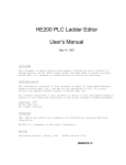
Horner APG’s
CAN Network
Repeater Module
User Manual for the
HE200CGM100
D ATA
CAN
PORT A
C o n tro lle r A rea N e tw o rk (C A N )
Iso la ted G a tew ay/R e p e a ter
RX TX
R S -232
PORT
+
29 October 1998
D ATA
1
CAN
PORT B
MAN0008-01
PREFACE
Page ii
PREFACE
This manual explains how to use the Horner APG CAN Network Repeater
Module for use in Controller Area Networks.
Copyright (C) 1997 Horner APG, LLC., 640 North Sherman Drive, Indianapolis
Indiana 46201-3899. All rights reserved. No part of this publication may be
reproduced, transmitted, transcribed, stored in a retrieval system, or translated
into any language or computer language, in any form by any means, electronic,
mechanical, magnetic, optical, chemical, manual or otherwise, without the prior
agreement and written permission of Horner APG, LLC.
All software described in this document or media is also copyrighted material
subject to the terms and conditions of the Horner Software License Agreement.
Information in this document is subject to change without notice and does not
represent a commitment on the part of Horner APG, LLC.
SDS is a trademark of Honeywell, Inc.
DeviceNet is a trademark of Allen Bradley.
PREFACE
Page iii
LIMITED WARRANTY AND LIMITATION OF LIABILITY
Horner APG, LLC. Inc. ("HE-APG") warrants to the original purchaser that the
HE200CGM100 manufactured by HE-APG is free from defects in material and
workmanship under normal use and service. The obligation of HE-APG under
this warranty shall be limited to the repair or exchange of any part or parts which
may prove defective under normal use and service within two (2) years from the
date of manufacture or eighteen (18) months from the date of installation by the
original purchaser whichever occurs first, such defect to be disclosed to the
satisfaction of HE-APG after examination by HE-APG of the allegedly defective
part or parts. THIS WARRANTY IS EXPRESSLY IN LIEU OF ALL OTHER
WARRANTIES EXPRESSED OR IMPLIED INCLUDING THE WARRANTIES OF
MERCHANTABILITY AND FITNESS FOR USE AND OF ALL OTHER
OBLIGATIONS OR LIABILITIES AND HE-APG NEITHER ASSUMES, NOR
AUTHORIZES ANY OTHER PERSON TO ASSUME FOR HE-APG, ANY
OTHER LIABILITY IN CONNECTION WITH THE SALE OF THIS
HE200CGM100. THIS WARRANTY SHALL NOT APPLY TO THIS PC CPU OR
ANY PART THEREOF WHICH HAS BEEN SUBJECT TO ACCIDENT,
NEGLIGENCE, ALTERATION, ABUSE, OR MISUSE. HE-APG MAKES NO
WARRANTY WHATSOEVER IN RESPECT TO ACCESSORIES OR PARTS
NOT SUPPLIED BY HE-APG. THE TERM "ORIGINAL PURCHASER", AS
USED IN THIS WARRANTY, SHALL BE DEEMED TO MEAN THAT PERSON
FOR WHOM THE HE200CGM100 IS ORIGINALLY INSTALLED.
THIS
WARRANTY SHALL APPLY ONLY WITHIN THE BOUNDARIES OF THE
CONTINENTAL UNITED STATES.
In no event, whether as a result of breach of contract, warranty, tort (including
negligence) or otherwise, shall HE-APG or its suppliers be liable of any special,
consequential, incidental or penal damages including, but not limited to, loss of
profit or revenues, loss of use of the products or any associated equipment,
damage to associated equipment, cost of capital, cost of substitute products,
facilities, services or replacement power, down time costs, or claims of original
purchaser's customers for such damages.
To obtain warranty service, return the product to your distributor with a
description of the problem, proof of purchase, post paid, insured and in a suitable
package.
PREFACE
Page iv
TABLE OF CONTENTS
HE200CGM100 Features .
.
.
.
.
.
.
.
1
HE200CGM100 Overview .
.
.
.
.
.
.
.
1
HE200CGM100 Specifications .
.
.
.
.
.
.
2
HE200CGM100 LED Indicators and Connectors Pin-outs .
.
3
HE200CGM100 Installation
.
5
.
.
.
.
.
.
CAN Network Repeater Module
Page 1
HE200CGM100 FEATURES
•
•
•
•
•
•
Microprocessor controlled re-clocking repeater
Bi-directional CAN message FIFO (first in first out)
Programmable CAN Baud rate up to 1 MHz
Integral RS-232 port for configuration and monitoring
1000V isolation
Wide range DC voltage input power
HE200CGM100 OVERVIEW
The HE200CGM100 is an intelligent CAN network isolating repeater.
CAN (Controller Area Network) is the basis for networking protocols used in automotive, and
more recently, industrial control applications. Published application protocols which use CAN
include SDS (MicroSwitch) and DeviceNet (Allen Bradley).
In a typical CAN network, each device is assigned a unique CAN node address (ID) to arbitrate
network communication.
Depending on the application protocol used, these IDs are assigned in the range of 0 to 253.
Therefore, up to 254 devices may be logically attached to a CAN network.
However, the use of standard CAN transceiver chips limits the number of physically attached
devices to 64. Thus, to reach the logical limit of 254 devices, up to three smart CAN repeaters
are used to connect groups of devices together.
A CAN network (without repeaters) should be limited to a maximum cable length of 1500 feet
(assuming a Baud rate of 125 kHz). With repeaters, this limit may be extended to 6000 ft.
In conclusion, the HE200CGM100 CAN repeater's 1000V isolation virtually eliminates problems
associated with ground potential differences that are inherent in long cable drops on many local
area networks.
CAN Network Repeater Module
Page 2
HE200CGM100 SPECIFICATIONS
I/O SPECIFICATIONS
PARAMETER
MINIMUM
MAXIMUM
UNITS
125
1000
kHz
1000
N/A
VDC
PARAMETER
MINIMUM
MAXIMUM
UNITS
Input Voltage
8
32
VDC
N/A
2.88 @ 24VDC
Watts
MINIMUM
MAXIMUM
UNITS
0
+60
Deg C
-40
+85
Deg C
5
95
% RH
Can Baud Rates
CAN Port A to B Isolation
POWER LOAD SPECIFICATIONS
Typical Power Consumption
ENVIRONMENTAL SPECIFICATIONS
PARAMETER
Operating Temperature
Storage Temperature
Humidity (Non-condensing)
CAN Network Repeater Module
Page 3
HE200CGM100 LED INDICATORS
•
There are four LED indicators on the HE200CGM100. Below is a description of each of
them.
Indicator
Color
Description
CAN Port A DATA
Red
CAN Port B DATA
Red
RS232 Port RX
Red
RS232 Port TX
Green
ON when CAN Port A
is active
ON when CAN Port B
is active
ON when RS232 Port
receives data
ON when RS232 Port
transmits data
HE200CGM100 CONNECTOR PINOUTS
•
The V-, GND and AV- signals are common to each other. The CAN Port B connector signals
are isolated from all other signals.
POWER CONNECTOR
Pin
Signal
Description
1
V-
2
V+
Input power supply
ground
Input power supply
voltage
RS-232 PORT CONNECTOR
Pin
Signal
Description
Direction
1
2
3
4
5
6
7
8
9
DCD
TXD
RXD
DTR
GND
DSR
CTS
RTS
RI
Always high
Transmitted Data
Received Data
Ignored
Ground
Always high
Clear to Send
Request to Send
Always high
Out
Out
In
In
Out
In
Out
Out
CAN Network Repeater Module
Page 4
CAN PORT A CONNECTOR
Pin
Signal
Description
1
AV-
2
AD+
CAN Port A return for
pins 2 and 3
CAN Port A Data +
3
AD-
CAN Port A Data –
4
ASHLD
CAN Port A Cable
Shield
CAN PORT B CONNECTOR
Pin
Signal
Description
1
BV-
2
BD+
CAN Port B return for
pins 2 and 3
CAN Port B Data +
3
BD-
CAN Port B Data –
4
BSHLD
CAN Port B Cable
Shield
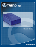
DIAGRAM OF PORT LOCATIONS
RS-232 PORT
CAN
PORT A
Controller Area Network (CAN)
Isolated Gateway/Repeater
PIN 1
RS-232
PORT
PIN 1
CAN
PORT B
External Power
Connector
CAN PORT B
CAN Network Repeater Module
Page 5
HE200CGM100 INSTALLATION
Power Connection
The CAN Network Repeater Module is powered by 8-32VDC and requires approximately 2.8
Watts @ 24VDC. The power supplied to the repeater must be isolated from ALL other system
power supplies. For example, the repeater SHOULD NOT be powered from the 33VDC power
terminals on the HE200PLC084 conveyer controller. A simple solution is to use an Archer 2731652 AC Adapter available from Radio Shack. This device provides 12VDC at 500mA.
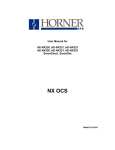
CAN Connection
The following diagram shows how to properly wire multiple nodes together on the CAN network:
Node 1
Node 2
Node 3
Node N
Terminal 1
Terminal 2
R
Terminal 3
Terminal 4
Cable Shield (not connected to Terminals 2 or 3)
R = 120 Ohm Resistor
CAN Wiring Rules
1) A CAN network should be wired in a daisy-chained fashion, such that there are exactly two
physical endpoints on the network.
2) The two nodes at the physical endpoints should have 120 ohm terminating resistors
connected across terminals 2 and 3.
3) The data conductors (terminals 2 and 3) should be a 24 AWG shielded twisted pair, with 120ohm characteristic impedance.
4) Notice that for a section of cable between two nodes, the cable shield is connected to
terminal 4 at one end of the cable only.
5) A CAN network (without repeaters) should be limited to 64 nodes with a maximum cable
length of 1500 ft.
6) Up to four CAN network segments, which adhere to the above five rules, may be connected
together using three CAN repeaters (HE200CGM100). In this manner, a CAN network may
be extended to 253 nodes with a total cable distance of 6000 ft.
7) Each HE200PLC084 unit is assigned a unique Network ID (Local PLC number) by the
HEPLC programming software, via the RS485 port. Repeaters DO NOT have Network
Addresses.
CAN Network Repeater Module
Page 6
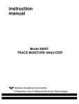
CAN Repeater Wiring:
For wiring purposes, a repeater can be thought of as two CAN nodes, each of which is part of a
different network segment (as shown in the diagram below).
HE200CGM100
Pin 1
Connects to a
Maximum of
63
other nodes
R
CAN
Port A
Pin 4
Pin 4
CAN
Port B
R
Connects to a
Maximum of
63
other nodes
Pin 1
R = 120 Ohm Resistor
Cable Shield (not connected to Terminals 2 or 3)
MECHANICAL INSTALLATION
•
See attached “CANBUS REPEATER BASE” drawing (on the next page) for mechanical
mounting considerations. For best results, mount to a metal backplate that is electrically
connected to earth ground.